MP03XX440-20中文资料
MM440变频器课件

K3 OFF OFF OFF
K2 OFF OFF ON
K1 OFF ON OFF
输出频率 OFF 固定频率1 固定频率2
OFF
ON ON ON ON
ON
OFF OFF ON ON
ON
OFF ON OFF ON
固定频率3
固定频率4 固定频率5 固定频率6 固定频率7
多段速对应关系
频率设定 P1001 P1002 P1003 P1004 P1005 P1006 P1007 P1008 P1009 P1010 P1011 P1012 P1013 P1014 P1015
电机主要参数设置
P0304 (电机额定电压) P0305(电机额定电流) P0307(电机额定功率) P0308(电机额定功率因数) P0309(电机额定效率) P0310(电机额定频率) P0311(电机额定转速)
MM440变频器多段速频率设定
序号 1 2 3 4 5 6 7 8 9 10 11 12 13 14 15 16 17 18 19 20 21 变频器参数 P0304 P0305 P0307 P0310 P0311 P1000 P1080 P1082 P1120 P1121 P0700 P0701 P0702 P0703 P1001 P1002 P1003 P1004 P1005 P1006 P1007 出厂值 230 3.25 0.75 50.00 0 2 0 50 10 10 2 1 12 9 0.00 5.00 10.00 15.00 20.00 25.00 30.00 设定值 380 0.35 0.06 50.00 1430 3 0 50.00 10 10 2 17 17 17 15.00 25.00 40.00 -15.00 -25.00 -40.00 50.00 电动机的额定电压( 380V ) 电动机的额定电流( ) 电动机的额定功率( 60W ) 电动机的额定频率( 50Hz ) 电动机的额定转速( 1430 r/min ) 固定频率设定 电动机的最小频率( 0Hz ) 电动机的最大频率( 50Hz ) 斜坡上升时间( 10S ) 斜坡下降时间( 10S ) 选择命令源( 由端子排输入 ) 固定频率设值(二进制编码选择+ON命令) 固定频率设值(二进制编码选择+ON命令) 固定频率设值(二进制编码选择+ON命令) 固定频率1 固定频率2 固定频率3 固定频率4 固定频率5 固定频率6 固定频率7 功能说明
MICROMASTER 440通用变频器

目录1 MICROMASTER 440 变频器的参数.................................................................... ................................... 1-1 1.1 MICROMASTER 440 变频器的系统参数.................简介.......................................................................1-2 1.2 快速调试(P0010=1)..... ................... ....................................................................................................1-4 1.3 命令和驱动数据组一概览........ ............. ......................... ......................................................................1-51.4 参数的说明......................................... .................................................................................................1-62 功能框图.............................................. .................................................................................................... 2-13 二进制互联连接(BiCo)功能................................................................................................................ 3-1 3.1 概述..................................................................................................................................................... 3-2 3.2 怎样进行BiCo 设置?......................................................................................................................... 3-2 3.3 BiCo 控制字和状态字的用法................................................................................................................. 3-43.4 BiCo 的连接............................................................ ............................................................................. 3-54 通讯....................................................................... .................................................................................. 4-1 4.1 采用的串行通讯接口............................................................................................................................ 4-2 4.2 串行通讯的工作情况............................ ................................................................................................. 4-2 4.2.1 概述.................................................................................................................................................... 4-2 4.2.2 RS485 的排障..................................................................................................................................... 4-3 4.3 采用通用的串行接口协议................................................................................ ................... ...................4-3 4.3.1 通讯报文的结构............................................................ ...................................................................... 4-4 4.3.2 USS 协议有关信息的详细说明........................................... .............................................................. 4-4 4.3.3 有效的数据字符.................................................................... .............................................................. 4-5 4.3.4 USS 的任务和应答.............................................................................................................................. 4-7 4.3.5 PKW 举例:..................................................................... .................................................................4-10 4.3.6 PZD 区域(过程数据区)................................................... .................................................................4-12 4.3.7 任务报文(主站→MICROMASTER4)................................................................................................4-12 4.3.8 应答报文(MICROMASTER4→主站)............................. ..................................................................4-13 4.3.9 MICROMASTER4 有关USS 通讯的参数设置.................. ..................................................................4-15 4.3.10 基本设定................................................................................................................... ........................4-16 4.3.11 一般的高级设置.................................................................................................................................4-16 4.3.12 较复杂的高级设置.............................................................................................................................4-17 4.3.13 与早期MICROMASTER 产品的兼容性....... . ...................................................................................4-17 4.3.14 读出和写入参数............................................... .................................................................................4-18 4.3.15 广播方式............................................................................................................................................4-19 4.3.16 通过USS 利用BiCo(二进制互联连接)...... . ....................................................................................4-19 4.4 PROFIBUS....................................................... . .................................................................................. 4-20 4.4.1 概况............................................................... . .................................................................................. 4-20 4.4.2 PROFIBUS 的使用........................................ .................................................................................... 4-20 4.5 PROFIBUS 模板............................................. . .................................................................................... 4-214.5.1 PROFIBUS 模板的特点................................. . .................................................................................. 4-215 高级操作板(AOP)..................................................... . .......................................................................... 5-1 5.1 警告和说明........................................................................ .................................................................... 5-4 5.1.1 特殊键的功能...................................................................................................................................... 5-4 5.2 应用举例............................................................................... . .............................................................. 5-5 5.2.1 采用AOP 控制单台变频器.......................................................... ....................................................... 5-55.2.2.3 网络控制-PC 方式.................................................................................................................... 5-7 5.2.3 参数的“读出”.............................................................. ................................................................. 5-8 5.2.4 参数的“下载”.................................................................. ............................................................... 5-9 5.2.5 AOP 的参数.................................................................... . ..................................................................5-10 5.2.6 从站方式和DriveMonitor 的操作................ . ....................................................................................5-10 5.2.7 MM3 参数的读出..................................... . .........................................................................................5-11 5.2.8 定时器的操作........................................... . .........................................................................................5-11 5.3 AOP 开始工作........................................................................................................................................5-14 5.3.1 接通电源和初始化............. . ...............................................................................................................5-14 5.3.2 语言文本的选择...................................... . ..........................................................................................5-15 5.3.3 开机“帮助”............................... . .....................................................................................................5-15 5.3.4 常规的操作屏幕.............................. . ..................................................................................................5-15 5.3.5 主菜单(机旁操作方式).................................... . ..............................................................................5-16 5.3.6 请求等待................................................................ ............................................................................5-17 5.4 操作菜单................................................................................................................................................5-17 5.4.1 机旁操作方式下的操作........................................................................................................................5-17 5.4.1.1 通讯故障..........................................................................................................................................5-18 5.4.1.2 显示变频器的状态............... ............................................................................................................5-18 5.4.1.3 变频器类型的检验..................... ......................................................................................................5-18 5.4.2 主站方式下的操作................ . ............................................................................................................5-18 5.4.2.1 广播操作方式........................................... . .....................................................................................5-19 5.4.2.2 通讯故障..........................................................................................................................................5-19 5.5 选择操作方式.........................................................................................................................................5-19 5.5.1 机旁操作方式........................................................................................................... ......................... 5-20 5.5.2 主站方式................................................................................................................... ......................... 5-20 5.5.3 内部方式................................................................................................................... .........................5-20 5.5.4 从站方式.............................................................................................. ............................................. 5-20 5.5.5 PC 方式..................................................................................................... ........................................ 5-21 5.6 参数的访问............................................................................................................................................ 5-21 5.6.1 标准访问级的参数....................................................................... ...................................................... 5-21 5.6.2 功能键的使用................................................................................ .................................................... 5-22 5.6.2.1 屏幕显示滚动功能................................................................ .......................................................... 5-22 5.6.2.2 修改参数数值的某一位数字................................................ ............................................................ 5-22 5.6.2.3 跳转功能.......................................................................................................................................... 5-22 5.6.3 专家级参数................................................................................. ....................................................... 5-23 5.6.3.1 下标参数.............................................................................. ........................................................... 5-23 5.6.4 AOP 存储的参数组................................................................... ......................................................... 5-24 5.6.5 工程设计.................................................................................... ........................................................ 5-24 5.7 AOP 设定和组态.................................................................................................................................... 5-25 5.7.1 设定菜单..................................................................... ....................................................................... 5-25 5.7.1.1 背景亮度......................................................................................................................................... 5-25 5.7.1.2 屏幕对比度............................................................. ....................................................................... 5-26 5.7.1.3 用大字符显示.................................................................................................................................. 5-265.7.1.7 参数组的名称..................................................................................... ........................................... 5-27 5.7.1.8 设定时间/日期.......................................... ..................................................................................... 5-28 5.7.1.9 AOP 复位....................................................................................................................................... 5-28 5.8 故障指示............................................................................................................................................... 5-29 5.8.1 故障屏幕...................................................................................... ..................................................... 5-29 5.8.2 报警屏幕............................................................................................................................................ 5-30 5.8.3 多重故障................................................................................. .......................................................... 5-30 5.8.4 多重报警................................................................................. .......................................................... 5-30 5.8.5 故障和报警同时发生............................................................... .......................................................... 5-31 5.8.6 变频器的故障码....................................................................... ......................................................... 5-31 5.8.7 变频器的报警码........................................................................................ ........................................ 5-315.8.8 变频器的故障/ 报警记录(P0947).............................................................................................. 5-316 编码器模板.............................................................................................................................................. 6-1 6.1 前言...................................................................................................................................................... 6-2 6.2 一般情况............................................................................................................................................... 6-3 6.3 安装...................................................................................................................................................... 6-4 6.3.1 准备工作................................................................................... ........................................................ 6-4 6.3.1.1 变频器的准备工作........................................................................................................................... 6-4 6.3.1.2 编码器模板的准备工作.......................................................... ......................................................... 6-5 6.3.2 接线方法的举例.................................................................................................................................. 6-8 6.4 调试................................................................................................................................................................. 6-9 6.4.1 TTL 编码器............................................................. ...........................................................................6-10 6.4.2 HTL 编码器................................................................... .....................................................................6-11 6.4.3 外接电源......................................................................... ...................................................................6-11 6.4.4 编码器模板的参数化........................................................ ..................................................................6-12 6.5 故障的排除............................................................................................................................................6-14 6.5.1 LED 指示灯............................................................ ...........................................................................6-14 6.5.2 故障码....................................................................... ........................................................................6-156.6 编码器模板的技术规格................................................... ......................................................................6-157 MICROMASTER 440 变频器的制动电阻..................................... ...........................................................7-1 7.1 技术数据...................................................................................... .........................................................7-2 7.2 安装.......................................................................................................................................................7-2 7.3 接线.......................................................................................................................................................7-2 7.4 制动电阻的接线和外形尺寸...................................................................................................................7-37.5 制动电阻的选型........................................................... .........................................................................7-48 选件安装图............................................................................................................................................... 8-1插图图4-1 典型的RS485 多站接口.................................................................................................................... 4-3 图4-2 通讯报文的结构................................................................................................................................. 4-4 图4-3 地址(ADR)的位号......................................................................................................................... 4-4图6-1 编码器模板的外观........................................................................................ .................................... 6-3 图6-2 变频器的铭牌........................................................................................................... ........................ 6-4 图6-3 选件的安装顺序........................................................................................................ ....................... 6-5图6-4 屏蔽接线端和PE 端子.......................................................................................... ......................... 6-5 图6-5 编码器模板上的LED 指示灯................................................................................. ......................... 6-6 图6-6 编码器模板的DIP 开关................................................................................................ .................... 6-7 图6-7 TTL 编码器的接线(5V DC) ................................................................................ ............................ 6-8 图6-8 HTL 编码器的接线(18V DC) .................................................................................. ........................ 6-8 图6-9 具有外接电源的编码器............................................................................................. ........................ 6-9 图6-10 编码器模板的安装方法....................................................................................... ............................ 6-9 图6-11 编码器模板上的LED 指示灯..........................................................................................................6-14表格表3-1 BiCo 的连接(r0019 至r0054)..................................... ................................................................. 3-5 表3-2 BiCo 的连接(r0055 至r1119)....................................... ............................................................. 3-6 表3-3 BiCo 的连接(r1170 至r2050).......................................... .......................................................... 3-7 表3-4 BiCo 的连接(r2053 至r2294)............................................ ........................................................ 3-8 表4-1 任务识别标记ID 的定义............................................................ ....................................................... 4-7 表4-2 应答识别标记ID 的定义............................................................ ....................................................... 4-8 表4-3 对应答识别标记ID 的错误数值=“任务不能执行”的定义............... .................................................. 4-9 表4-4 PZD 区的结构..................................................................................... ..............................................4-12 表4-5 变频器的控制字(STW)................................................................ ................................................4-12 表4-6 变频器的状态字(PZD).................................................................. ...............................................4-13 表4-7 实际例子........................................................................................ ....................................................4-14 表4-8 比较表(MICROMASTER4/早期生产的MIsCROMASTER 变频器). ............................................4-18 表4-9 PROFIBUSSUB-D 插座的插针功能分配.............................................. ............................................ 4-23 表4-10 与数据传输速率相应的最大电缆长度................................................. ............................................ 4-23 表4-11 插头/座和电缆的订货号........................................................................ ............................. ........... 4-23 表4-12 技术数据.............................................................................................. ........................... .............. 4-24 表4-13 有关PROFIBUS 的订货资料................................................................... ...................................... 4-241 MICROMASTER 440 变频器的参数1.1 MICROMASTER 440 变频器的系统参数简介“参数说明”的编排格式如下。
SX440中文说明书

SX440发电机自动电压调节器使用手册版本 1.0日期:2015/06/29SX440版本历史记录:日期版本内容2015-06-29 1.0首次发行目录1.技术参数 (3)2.接线 (4)3.调节 (4)4.磁场初期电压诱起 (6)5.并网功能 (6)1.技术参数项目参数内容检测与电源输入电压190~264VAC单相二线频率50/60Hz以跨接铜片设定输出电压207VAC输入时最大90VDC电流连续4A,非连续为10秒内10A电阻最小15Ohm调压精度≤±1%(发动机转速变动在4%内)温差稳定度每℃变化,电压漂移0.05%外部电压调节用1K Ohms1Watt电位器时为±8%电压缓慢建立时间2秒DROOP无功调差最高灵敏度0.07A对应5%压降(PF=0时)最大输入0.33A 电压建立在AVR输入端子需剩磁电压5VAC以上消耗功率最大12Watt低频保护出厂预设:95%Hz斜率:下降至30Hz时为170%电压修正最大输入:±5VDC(模拟输入)灵敏度:每1VDC可调节5%发电机电压输入电阻:1K Ohm电流补偿负载:10Ohm尺寸150mm L*135mm W*48mm H重量0.45KG±2%2.接线2.1.K1、K2:为磁场开关,不使用时须短路跨接。
2.2.P2、P3:为磁场电源输入端子。
2.3.3、2:为检测电源输入端子。
2.4.1、2:为外接VR,不使用时须短路跨接。
2.5.X、XX:X磁场+端、XX磁场−端。
2.6.S1、S2:DROOP CT输入端。
2.7.A1、A2:VAR/PF控制输入(V/TRIM)。
2.8.AB、C:90KW以下A、C跨接,90KW~550KW B、C跨接,550KW以上A、B跨接。
2.9.J1~J8:选择跨接线2-3、4-5、6-7。
(如图二)2.10.建议:使用一较高遮断容量之保险加装于励磁场电源,熔丝容量须依实际满载励磁场电流的120%。
Sun SPARC

Sun SP ARC® EnterpriseM4000/M5000 伺服器產品說明適用於 XCP 版本 1041 Sun Microsystems, Inc.文件號碼 820-2445-102007 年 6 月,修訂版 A請將您對本文件的意見提交至:/hwdocs/feedback請回收Copyright 2007 Sun Microsystems, Inc., 4150 Network Circle, Santa Clara, California 95054, U.S.A. 與 FUJITSU LIMITED, 1-1, Kamikodanaka 4-chome, Nakahara-ku, Kawasaki-shi, Kanagawa-ken 211-8588, Japan 。
版權所有。
Sun Microsystems, Inc. 和 Fujitsu Limited 對於本文件所述之相關產品和技術,分別擁有或控制智慧財產權,而且此類產品、技術和本文件皆受著作權法、專利法、其他智慧財產權法以及國際公約所保護。
在上述的產品、技術和本文件中,Sun Microsystems, Inc. 和 Fujitsu Limited 的智慧財產權包括 /patents 上所列的一項或多項美國專利,以及在美國或其他國家/地區擁有的一項或多項其他專利或專利申請,但並不以此為限。
本文件及相關產品與技術在限制其使用、複製、發行及反編譯的授權下發行。
未經 Fujitsu Limited 、Sun Microsystems, Inc 及其適用授權人 (如果有) 事先的書面許可,不得使用任何方法、任何形式來複製本產品、技術或文件的任何部分。
提供本文件並不表示您享有相關產品或技術的任何明示或暗示性權限或授權,同時本文件不包含或代表 Fujitsu Limited 、Sun Microsystems, Inc. 或任何關係企業的任何承諾。
Micromaster440 调试参数

Parameter (参数)Value (设定值)Description (描述)P10802最低频率P108250最高频率P112010斜坡上升时间-电动机从静止状态加速到最高频率所用的时间(如果设定的斜坡上升时间过短,就可能导致变频器跳闸--过电流)P112110斜坡下降时间-电动机从最高频率减速到静止停车所用的时间(如果设定的斜坡下降时间过短,就可能导致变频器跳闸--过电流/过电不用快速调试1结束快速调试,并按工厂设置使参数复位2结束快速调试3结束快速调试,只进行电动机数据的计算P00033P07331变频器运行准备就绪P00101P0700.01BOP 控制有效P0700.16COM 链路的通讯板(CB)设置P0733.01P0733.11P08102090.15(.F.)远程控制 (2090.F) / MCC 控制 0P0918XX 地址49CB.Address 通讯地址P1000.01电动电位计设定P1000.16通过COM 链路的CB 设定P2051.052P2051.121P2051.227P2051.353P2051.432P2051.535P0601.01PTC (正温度系数)热敏元件 第一驱动数据组(DDS )P0601.11PTC (正温度系数)热敏元件 第二驱动数据组(DDS )P0604XX 电动机温度保护的门限值0除报警外无应对措施1报警并降低最大电流Imax (引起输出频率降低)2报警和跳闸(F0011)P062520电动机运行的环境温度P0640150%电动机过载因子P3900结束快速调试P0610电动机过温应对措施↓↓进入数据计算Busy...↓主电源接触器吸合第一步完成,重新核对参数↓调设状态字 P2051↓温度保护项调设。
MM440_[Chinese]
![MM440_[Chinese]](https://img.taocdn.com/s3/m/4755b49cdd88d0d233d46ac2.png)
矢 量 型
MM440
Standard Drives A&D SD
A&D SD PRODUCT 4
1
MICROMASTER 440 - 技 术 性 能 概 要
有 A, B, C, D, E, F 六 种 外 形 结 构 的 机 壳 输 出 功 率 可 达 75 kW (恒 力 矩 )或 90 kW ( 变 力 矩) 矢 量 控 制 (无 编 码 器 ) 6 DI, 2 AI, 3 DO (继 电 器 ), 2 AO 集成的制动斩波器 恒 力 矩 方 式 下 过 载 能 力 为 200% 额 定 电 流 ,持 续 时 间 3 秒; 150% 额 定 电 流 ,持 续 时 间 60 秒;过 载 间 隔 时 间 5 分 钟 集 成 的 高 性 能 PID 控 制 器 (参 数 自 动 整 定 ) 通 过 了 CE, UL, CUL和 c-tick 的 认 证 防 护 等 级 为 IP20 / NEMA 1 输 出 频 率 0 - 650Hz 直流制动和复合制动功能 工 作 环 境 温 度 -10°C to 50°C 内 部 互 连 采 用 BiCo 技 术
Standard Drives A&D SD
A&D SD PRODUCT 4
6
MICROMASTER 440
矢量控制
输出频率 输 出 频 率 不 超 过 200 Hz ( V/ f工 作 方 式 时 可 达 650 Hz)
具有磁通监控的完整电动机模型 甚 至 在 频 率 < 2 Hz 和反 转 时 也 有 优 良 的 力 矩 输 出 特 性
电 动 机 识 别 程序 监 测 电 动 机 的 全 部 电 抗 ,实 现 可 靠 的 闭 环 控 制[或 :调 节]
440变频器使用大全
1 2 3 4 5 6 7 8 9 10 11 12 13 14 15 16 17 A B C D E F
MICROMASTER 440变频器 0.12kW - 250kW
系统参数 排障 MICROMASTER 440 的技术规格 可选件
使用大全 用户文件
电磁兼容性 MICROMASTER 440 变频器的参数表 功能框图 二进制互联连接(BiCo)功能 通讯 高级操作板( AOP ) 编码器 制动电阻
Email: techsupport@ad.siemens.de 星期一至星期五:上午 7: 00 至下午 5: 00 (当地时间) 西门子(中国)有限公司技术支持部 北京 电话: 传真: 010 – 64738566 010 – 64731096,647地址 用户可以在以下网址查到技术资料和一般信息: http:///products/sd。 联系地址: 如果您在阅读本手册时有什麽疑问或问题,请根据本手册封底的地址与西门子公司的办事处联 系。
本手册中对某些有效的功能可能未加说明。但是,在新的控制装置 中或进行服务时,并不因为西门子公司提供了这些功能而要承担任 未经书面许可,不得翻印、传播、或使用本手册及其相关内 何责任。 容。违者将对所造成的损害负法律责任。西门子公司保留一切 编审过程中,我们对本手册的内容与所述的硬件和软件的一致性进 权利,包括由专利许可、实用样机注册、或工程设计等所产生 行了审核。但是,仍然可能存在矛盾和谬误的地方,不可能保证它 的所有权利。 们完全一致。我们将定期检查本手册中涵盖的内容,并在以后修订 的版本中予以必要的修正。欢迎提出改进的建议。 © Siemens AG 2001。保留一切权利。 西门子公司的手册都是用无氯纸张印刷的,这种纸张的生产原料来 源于可持续生长的森林。打印和装订的过程中未使用化学溶剂。 MICROMASTER® 是西门子公司已注册的商标。 保留不予先通知而修改本手册的权利。
DP440维修手册中文版(一)

曝光灯位置传感器(PS1) 原稿盖板传感器
曝光灯 反光镜
反光镜
原稿尺寸传感器5 透镜组件 感光装置 原稿尺寸传感器4 原稿尺寸传感器123
3
2.工作时序
(1)扫描机构操作时序
1)按下制版键 ,扫描机构从右向左移动, 扫描原稿。
扫描机构 曝光灯扫描初始位置
2)原稿扫描结束后,曝光灯熄灭,曝光灯系 统减速、停止。再向右运动,停止在曝光灯 位置传感器(PS1)位置。
2 有效宽度
292.6 0.1mm
260.1 0.1mm
260.2 0.2mm
16
制版/供版/卸版机构
外观与编号
309 0.5(DP-440), 309 0.2(DP-430) 292.57 0.1(DP-440), 292.7 0.1(DP-430)
热敏打印线
电热调节器 标签 :DP-440 / DP-340
12
原稿
-1
CN12-11
1
主板 CN12-1
-12
规格
感光装置CCD 下表是感光装置的规格列表
No. 1 周期
项 目
2 频率
3 像素
4 读取宽度(这不表示机器可以处理的扫描宽度)
5 分辨率
数 值 2.048 毫秒 / 线 2.5MHz 4800 像素 305mm 15.7 点/毫米(400DPI)
3)接下来,系统等待下一步的印刷工作。
(2)扫描机构操作时序(安装ADF后)
1)按下制版键 ,曝光灯向右移动,到达 原稿位置传感器(PS1)位置后,转向左 移动。
曝光灯扫描范围 曝光灯的初始位置
2)曝光灯向左移动到ADF曝光灯位置传感器 (PS2)位置后停止,开始扫描原稿。 扫描结束后,曝光灯向右运动,停止在曝 光灯位置传感器(PS1)位置。
开关电源驱动模块(PM40XXA) 说明书

开关电源驱动模块(PM40XXA)图1是为大功率开关电源设计的专业驱动模块,模块型号定义为:PM4020A和PM4060A两种,PM4020A最大驱动为(以MOS 管为例25A;MOS管)在应用驱动最老的MOS管是IRFP460内部电容大约6000P。
图2是PM4060A最大驱动能力为60A的MOS管或者IGBT管,两个电路图相同、不同的是所使用的驱动IC有区别,前面是使用的IR2101驱动IC、后面是使用IR2181驱动IC,两个驱动电路的脚列完全相同!可以直接代替使用。
上面两种模块的全部技术资料由(老铎)设计!所有出版在“电子制作网”上面。
并且由本网站提供完整的成品(如上图片)。
PM4020A每块30元;PM4060A每块 35元;具体订购方法请参考最后页。
采用该模块设计一个大功率1000W的开关电源是十分简单的事情,你不必花费更多的时间就可以完成,下面的设计是一个标准的开关电源电路图。
我们将连续出版模块的开发电路图和音响的开关电源,供爱好制作的朋友提供最大的方便。
电子制作网技术资料下载连接表凡是我们出版的制作技术资料的PDF文档,均在这里保留每个技术资料的PDF文档的连接。
发表技术问题到:我们的电子制作网 电子制作网提供关键套件 (电信站) (网通站)设计人:刘铎 实验人:老铎165v@ KA KB HOR VSRLOR DTHOL VSL LOL GND ISVCC 12345678910111213141516PIN16脚 标准单列直插全桥通用开关电源驱动模块IO GND 输入功率控制脉宽设置稳压控制(光耦K )稳压控制(光耦A )地右下驱动输出工作电压13V-18V输出电流控制(5V)右上驱动中点右上驱动输出地左下驱动输出左上驱动中点左上驱动输出工作频率 60KHz-80KHz-100KHz 误差2%最大能驱动65A 的MOS 管子VSL+HOL 和VSR+HOR 可工作在0V-600V如果没有特殊说明所有不同型号的半桥和半桥脚列相同及不同型号全桥和全桥脚列相同!不同型号半桥和半桥可以互相代换。
罗克韦尔 440G-MZ Guardmaster保护锁开关 说明书

产品目录号 440G-MZS20SNRJ、440G-MZS20SNRJE、440G-MZS20UNRJ、440G-MZS20UNRJE、440G-MZS20SNLJ、440G-MZS20SNLJE、440G-MZS20UNLJ、440G-MZS20UNLJE440G-MZ Guardmaster 保护锁开关2罗克⻙尔⾃动化出版物 440G-UM004E-ZH-P - 2021 年10 月440G-MZ Guardmaster 保护锁开关 ⽤⼾⼿册重要⽤⼾须知在安装、配置、操作或维护本产品之前,请阅读本文档以及“其他资源”章节所列的文档,了解关于安装、配置和操作该设备的信息。
除了所有适用的条例、法律和标准的要求之外,用⼾还必须熟悉安装和接线说明。
包括安装、调整、投⼊运⾏、使用、装配、拆卸和维护等在内操作必须由经过适当培训的人员根据适用的操作守则来执⾏。
如果未遵照制造商所指定的方式使用该设备,将可能导致该设备提供的保护失效。
在任何情况下,对于因使用或操作该设备造成的任何间接或连带损失,罗克⻙尔⾃动化公司概不负责。
本手册中包含的示例和图表仅用于说明。
由于任何具体安装都涉及众多变数和要求,罗克⻙尔⾃动化公司对于依据这些示例和图表所进⾏的实际应用不承担任何责任和义务。
对于因使用本手册中所述信息、电路、设备或软件而引起的专利问题,罗克⻙尔⾃动化公司不承担任何责任。
未经罗克⻙尔⾃动化公司的书⾯许可,不得复制本手册的全部或部分内容。
在整本手册中,我们在必要的地方使用了以下注释,来提醒您留意安全注意事项。
标签也可能位于设备表⾯或内部,提供具体的预防措施。
警告:标识在危险环境下可能导致爆炸,进而导致人员伤亡、物品损坏或经济损失的操作或情况。
注意:标识可能导致人员伤亡、物品损坏或经济损失的操作或情况。
注意符号可帮助您确定危险情况,避免发生危险,并了解可能的后果。
重要事项标识对成功应用和了解本产品有重要作用的信息。
电击危险:位于设备(例如,驱动器或电机)表面或内部的标签,提醒相关人员可能存在危险电压。
MP03HBN360-14中文资料

FEATURESs Dual Device Module s Electrically Isolated Package s Pressure Contact Construction s International Standard Footprint sAlumina (Non Toxic) Isolation MediumAPPLICATIONSs Motor Controls Controlled Rectifier Bridges s Heater Control sAC Phase ControlVOLTAGE RATINGSORDERING INFORMATIONOrder As:MP03HBT360-XX MP03HBN360-XX MP03HBP360-XXXX shown in the part number above represents the V RRM /100slection required, e.g. MP03HBT360-17Note: When ordering, please use the complete part number.KEY PARAMETERS V DRM 1800V I T(AV)355A I TSM(per arm)8100A V isol3000VReplaces January 2000 version, DS4484-5.0DS4484-6.1 June 200118001600140012001000800MP03XXX360-18MP03XXX360-16MP03XXX360-14MP03XXX360-12MP03XXX360-10MP03XXX360-08ConditionsT vj = 0˚ to 125˚C,I DRM = I RRM = 30mA V DSM = V RSM =V DRM = V RRM + 100V respectivelyLower voltage grades available.XXX shown in the part number above represents the circuit configuration required.Type NumberRepetitive PeakVoltages V DRM V RRMVTest ConditionsHalf wave resistive loadT case = 75˚C T case = 85˚C T heatsink = 75˚C T heatsink = 85˚CT case = 75˚C10ms half sine, T j = 130˚CV R = 010ms half sine, T j = 130˚CV R = 50% V DRMCommoned terminals to base plate.AC RMS, 1 min, 50HzSymbol I T(AV)I T(RMS I TSM I 2t I TSM I 2t V isolUnits A A A A A kA A 2s kA A 2s VMax.3553122762425608.10.33x1066.50.21x1063000ABSOLUTE MAXIMUM RATINGS - PER ARMStresses above those listed under 'Absolute Maximum Ratings' may cause permanent damage to the device. In extreme conditions, as with all semiconductors, this may include potentially hazardous rupture of the package. Appropriate safety precautions should always be followed. Exposure to Absolute Maximum Ratings may affect device reliability.ParameterMean on-state currentRMS valueSurge (non-repetitive) on-current I 2t for fusingSurge (non-repetitive) on-current I 2t for fusing Isolation voltageTest Conditionsdc Half wave 3 PhaseMounting torque = 5Nm with mounting compound Reverse (blocking)-Mounting - M5Electrical connections - M8-ParameterThermal resistance - junction to case (per thyristor or diode)Thermal resistance - case to heatsink (per thyristor or diode)Virtual junction temperature Storage temperature range Screw torqueWeight (nominal)THERMAL AND MECHANICAL RATINGSSymbol R th(j-c)R th(c-hs)T vj T stg --Units ˚C/kW ˚C/kW ˚C/kW ˚C/kW˚C ˚C Nm (lb.ins)Nm (lb.ins)gMax.0.1050.1150.120.051351355(44)9(80)950Min.-----–40---Units mA V/µs A/µsV m ΩTest ConditionsAt V RRM /V DRM , T j = 130˚C To 67% V DRM , T j = 130˚CFrom 67% V DRM to 600A, gate source 10V, 5Ωt r = 0.5µs, T j = 130˚CAt T vj = 135˚C. See note 1At T vj = 135˚C. See note 1ParameterPeak reverse and off-state current Linear rate of rise of off-state voltage Rate of rise of on-state currentThreshold voltage On-state slope resistanceDYNAMIC CHARACTERISTICS - THYRISTORSymbol I RRM /I DRM dV/dt dI/dtV T(TO)r TMax.5010005000.780.79Min.-----ParameterGate trigger voltage Gate trigger current Gate non-trigger voltage Peak forward gate voltage Peak forward gate voltage Peak reverse gate voltage Peak forward gate current Peak gate power Mean gate powerTest ConditionsV DRM = 5V, T case = 25o C V DRM = 5V, T case = 25o C At V DRM T case = 125o CAnode positive with respect to cathode Anode negative with respect to cathode-Anode positive with respect to cathode See table fig. 5-Symbol V GT I GT V GD V FGM V FGN V RGM I FGM P GM P G(AV)GATE TRIGGER CHARACTERISTICS AND RATINGSMax.31500.25300.255101005Units V mA V V V V A W WNote 1: The data given in this datasheet with regard to forward voltage drop is for calculation of the power dissipation in the semiconductor elements only. Forward voltage drops measured at the power terminals of the module will be in excess of these figures due to the impedance of the busbar from the terminal to the semiconductor.(with 50% V RSM at T case = 130˚C)specified conduction angles, sine wave 50/60Hzspecified conduction angles, square wave 50/60Hzon-state current at specified conduction angles,sine wave 50/60Hzon-state current at specified conduction angles,square wave 50/60Hzspecified values of heatsink thermal resistancefor specified values of heatsink thermal resistancePACKAGE DETAILSFor further package information, please visit our website or contact your nearest Customer Service Centre. All dimensions in mm, unless stated otherwise. DO NOT SCALE.POWER ASSEMBLY CAPABILITYThe Power Assembly group provides support for those customers requiring more than the basic semiconductor switch. Using CAD design tools the group has developed a flexible range of heatsink / clamping systems in line with advances in device types and the voltage and current capability of Dynex semiconductors.An extensive range of air and liquid cooled assemblies is available covering the range of circuit designs in general use today.HEATSINKSThe Power Assembly group has a proprietary range of extruded aluminium heatsinks. These were designed to optimise theperformance of Dynex semiconductors. Data with respect to air natural, forced air and liquid cooling (with flow rates) is available on request.For further information on device clamps, heatsinks and assemblies, please contact your nearest sales representative or customer service office.MOUNTING RECOMMENDATIONSAdequate heatsinking is required to maintain the basetemperature at 75˚C if full rated current is to be achieved. Power dissipation may be calculated by use of V T(TO) and r T information in accordance with standard formulae. We can provideassistance with calculations or choice of heatsink if required.The heatsink surface must be smooth and flat; a surface finish of N6 (32µin) and a flatness within 0.05mm (0.002") are recommended.Immediately prior to mounting, the heatsink surface should be lightly scrubbed with fine emery, Scotch Brite or a mild chemical etchant and then cleaned with a solvent to remove oxide build up and foreign material. Care should be taken to ensure no foreign particles remain.An even coating of thermal compound (eg. Unial) should be applied to both the heatsink and module mounting surfaces.This should ideally be 0.05mm (0.002") per surface to ensure optimum thermal performance.After application of thermal compound, place the modulesquarely over the mounting holes, (or ‘T ’ slots) in the ing a torque wrench, slowly a torque wrench, slowly tighten the recommended fixing bolts at each end, rotating each in turn no more than 1/4 of a revolution at a time. Continue until the required torque of 6Nm (55lb.ins) is reached at both ends.It is not acceptable to fully tighten one fixing bolt before starting to tighten the others. Such action may DAMAGE the module.CUSTOMER SERVICE CENTRESMainland Europe Tel: +33 (0)1 58 04 91 00. Fax: +33 (0)1 46 38 51 33North America Tel: 011-800-5554-5554. Fax: 011-800-5444-5444UK, Scandinavia & Rest Of World Tel: +44 (0)1522 500500. Fax: +44 (0)1522 500020SALES OFFICESMainland Europe Tel: +33 (0)1 58 04 91 00. Fax: +33 (0)1 46 38 51 33North America Tel: (613) 723-7035. Fax: (613) 723-1518. Toll Free: 1.888.33.DYNEX (39639) /Tel: (949) 733-3005. Fax: (949) 733-2986.UK, Scandinavia & Rest Of World Tel: +44 (0)1522 500500. Fax: +44 (0)1522 500020These offices are supported by Representatives and Distributors in many countries world-wide.© Dynex Semiconductor 2001 Publication No. DS4484-6 Issue No. 6.1 June 2001TECHNICAL DOCUMENTATION – NOT FOR RESALE. PRINTED IN UNITED KINGDOMHEADQUARTERS OPERATIONS DYNEX SEMICONDUCTOR LTD Doddington Road, Lincoln.Lincolnshire. LN6 3LF. United Kingdom.Tel: 00-44-(0)1522-500500Fax: 00-44-(0)1522-500550DYNEX POWER INC.99 Bank Street, Suite 410,Ottawa, Ontario, Canada, K1P 6B9Tel: 613.723.7035Fax: 613.723.1518Toll Free: 1.888.33.DYNEX (39639)This publication is issued to provide information only which (unless agreed by the Company in writing) may not be used, applied or reproduced for any purpose nor form part of any order or contract nor to be regarded as a representation relating to the products or services concerned. No warranty or guarantee express or implied is made regarding the capability, performance or suitability of any product or service. The Company reserves the right to alter without prior notice the specification, design or price of any product or service. Information concerning possible methods of use is provided as a guide only and does not constitute any guarantee that such methods of use will be satisfactory in a specific piece of equipment. It is the user's responsibility to fully determine the performance and suitability of any equipment using such information and to ensure that any publication or data used is up to date and has not been superseded. These products are not suitable for use in any medical products whose failure to perform may result in significant injuryor death to the user. All products and materials are sold and services provided subject to the Company's conditions of sale, which are available on request.All brand names and product names used in this publication are trademarks, registered trademarks or trade names of their respective owners.e-mail: power_solutions@Datasheet Annotations:Dynex Semiconductor annotate datasheets in the top right hard corner of the front page, to indicate product status. The annotations are as follows:-Target Information: This is the most tentative form of information and represents a very preliminary specification. No actual design work on the product has been started.Preliminary Information: The product is in design and development. The datasheet represents the product as it is understood but details may change.Advance Information: The product design is complete and final characterisation for volume production is well in hand.No Annotation: The product parameters are fixed and the product is available to datasheet specification.。
研华 PWS-440 强固型 PDA 用户手册说明书
用户手册PWS-440强固型PDA关于本手册本手册介绍如何安装、使用和维护PWS-440军事级手持设备。
未经制造商书面许可,不得以任何形式或者电子、机械等任何方式复制或使用本出版物的任何部分,包括影印、录制、或者信息存储和检索系统等。
针对本文档中的信息,研华保留随时变更的权利,恕不另行通知。
对于严苛环境的应用而言,研华有着多年的计算机设计经验。
这些应用需求来自于军事级与工业级用户,而PWS-440遵守MIL-STD-810G、MIL-STD-461E和IP67标准的相关要求,在产品对于EMC、EMI、温度、冲击、振动、湿度、灰尘及液体的防护性能方面符合规定。
此外,PWS-440能够满足全球各种工作环境下的军事级应用对于可靠性的要求。
随附本产品发行的文件为研华公司2013年版权所有。
Bluetooth为Bluetooth SIG的注册商标。
Microsoft、Windows和Active-Sync为Microsoft Corporation的注册商标或商标。
所有的产品品牌或产品型号均为公司之注册商标。
安规符合性声明FCC声明本品符合FCC规则第15款限制。
操作符合下列两种情况:(1)此装置不可产生干扰,且(2)此装置必须接受任何干扰,包括可能导致非预期造作的干扰。
注意:无线频率辐射暴露本设备的辐射功率输出远远低于FCC无线频率暴露限制标准。
尽管如此,在正常使用中应注意尽量减小该设备对人体潜在的辐射。
为设备连接外部天线时,应注意尽量减小该设备对人体潜在的辐射。
安装和使用时,天线与人体之间的距离应不少于20cm(8英尺),从而可以防止辐射超出FCC无线频率暴露的限制标准。
料号:2008044010第一版台湾印刷2014年1月PWS-440用户手册ii联邦通信委员会(FCC)声明根据FCC规则第15款,本设备已经过检测并被判定符合B级数字设备标准。
这些限制旨在为居住环境下的系统操作提供合理保护,使其免受有害干扰。
深蓝宇科技 PCM-4401 PCM系列工控主板 说明书
深圳市深蓝宇科技有限公司PCM-4401With 2*RS232/RS232/22*RS485/RS485/6*6*6*USB USB /2*2*PS2/SATA/PS2/SATA/PS2/SATA/VGA/LVDS/VGA/LVDS/VGA/LVDS/2*2*2*LAN LAN LAN/AUIOD /AUIOD /AUIOD/GPIO//GPIO/Parallel/Parallel/OnboardOnboard1GB DDR2产品用户手册深圳市深蓝宇科技有限公司声明本手册的版权归深圳市深蓝宇科技有限公司所有,并保留所有的权利。
本公司保留随时更改本手册的权利,恕不另行通知。
本手册的任何一部分未经过本公司明确的书面授权,任何其他公司或个人均不允许以商业获利目的来复制、抄袭、翻译或者传播本手册。
订购产品前,请向本公司详细了解产品性能是否符合您的要求。
产品并不完全具备本手册的所描述的功能,客户可根据需要增加产品的功能,具体情况请跟本公司的技术员或业务员联系。
本手册提供的资料力求准确和可靠。
然而,本公司对侵权使用本手册而造成后果不承担任何法律责任。
•使用前,请务必仔细阅读产品用户手册。
•当需要对产品进行操作时请先关闭电源。
•不要带电插拔,以免部分敏感元件被瞬间冲击电压烧毁。
•操作者需采取防静电措施后才能触摸或进行其他可能产生静电冲击的操作。
•避免频繁开机对产品造成不必要的损伤。
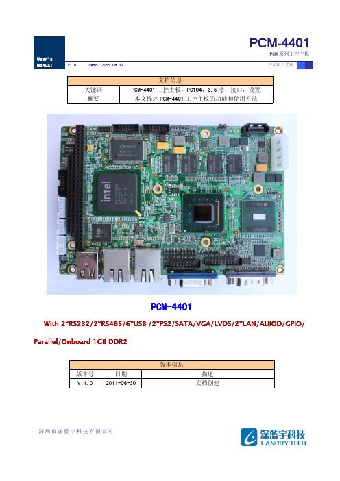
安全使用常识:产品用户手册深圳市深蓝宇科技有限公司目录第一章功能简介.............................................................................................................................................................41.1产品简介.................................................................................................................................................................41.2特征.........................................................................................................................................................................4第二章结构说明...............................................................................................................................................................52.1跳线设置.................................................................................................................................................................52.1_1COM2口RS232/RS485/RS422选择跳线-JP1、JP2、JP3、JP4、JP5...................................................62.1_2LVDS LCD 屏幕电压选择跳线–JLCD1.....................................................................................................62.1_3LVDS LCD 背光电压选择跳线–JBL1.......................................................................................................72.1_4CF 卡供电电压选择跳线–JCF1..............................................................................................................72.2接口说明.................................................................................................................................................................82.2_1电源插座-PWR1...............................................................................................................................................92.2_2串口-COM1.....................................................................................................................................................102.2_3串口-COM2.....................................................................................................................................................102.2_4GPIO 接口-GPIO .........................................................................................................................................102.2_5USB1-USB1、USB2接口................................................................................................................................102.2_6USB2/3-USB3、USB4、USB5、USB6接口....................................................................................................112.2_7VGA 接口—VGA ..............................................................................................................................................112.2_8网络端口–LAN1/2...................................................................................................................................112.2_9LVDS 接口-LVDS1 (12)2.2_10液晶屏背光控制-LCDB1.......................................................................................................................132.2_11音频输入输出接口-Audio ...................................................................................................................132.2_12CF 卡–CF1..............................................................................................................................................132.2_13PS2鼠标键盘-KM1..................................................................................................................................152.2_14PC/104接口-PC104 (15)第三章系统硬件资源说明..............................................................................................................................................173.1存贮器映射...........................................................................................................................................................173.2I/O 映射................................................................................................................................................................183.3中断资源配置.......................................................................................................................................................203.4看门狗...................................................................................................................................................................203.5GPIO .......................................................................................................................................................................20第四章、LCD/CRT 支持规格.............................................................................................................................................214.1显示支持模式.......................................................................................................................................................21第五章驱动安装.............................................................................................................................................................235.1VGA 和DVO . (23)产品用户手册深圳市深蓝宇科技有限公司5.2网络.......................................................................................................................................................................235.3音频.......................................................................................................................................................................235.4其它功能驱动.......................................................................................................................................................23第六章电气参数和机械尺寸..........................................................................................................................................246.1电气参数...............................................................................................................................................................246.2机械尺寸 (24)产品用户手册深圳市深蓝宇科技有限公司第一章功能简介1.1产品简介PCM-4401是一款性价比极高、尺寸及其紧凑的嵌入式控制模块。
第3章 西门子MM4XX变频器介绍
功能:线性U/f控制;多点设定的U/f控制;磁通 电流控制,内置PID控制器。
功率范围:7.5kW~250kW。
该变频器为西门子现行风机泵类主流专用变频器
➢ MM440变频器
该变频器为“通用型”变频器,主要应用 于三相电动机的变速驱动,也可以用于泵类、 风机等节能负载。是现行西门子“通用型” 主流变频器。
20 通讯
21 报警 / 警告 / 监控
22 工艺参量控制器(例如PID)
参数结构, 参数过滤器 P0004
P0004 = 2 变频器
P0004 = 8 模拟量 I/O
P0004 = 3 电机数据
1LA2063-4AB10 No UD 9880090-0030-0102
50 Hz /Y 230/400V
默认状态下使用的当前参数组是第0组参数,即 CDS0和DDS0。
举例来说,P1000的第0组参数,在BOP上显示为
,书本中常写作P1000.0;P1000[0];或者 P1000in000等形式。
将参数按照命令和驱动两大类分为三组,使得用 户可以根据不同的需要在一个变频器中设置多种
驱动和控制的配置,并在适当的时候根据需要进 行切换。
P0004 = 12 附加功能
P0004 = 13 电机的控制
P0004 = 22 PI-调节器
P0004 = 28
&
自由功能块
3.6 MM4x系列变频器参数的调试方法
3.6.1 调试步骤 通常一台新的MM4x变频器一般需要经过如下三个步 骤进行调试:
• 参数复位,是将变频器参数恢复到出厂状态下的默认 值的操作。一般在变频器出厂和参数出现混乱的时候进 行此操作。 • 快速调试状态,需要用户输入电机相关的参数和一些 基本驱动控制参数,使变频器可以良好的驱动电机运转。 一般在复位操作后,或者更换电机后需要进行此操作。 • 功能调试,指用户按照具体生产工艺的需要进行的设 置操作。这一部分的调试工作比较复杂,常常需要在现 场多次调试。
SM1900M 4-20mA 防护型温度采集模块说明书

SM1900M4-20mA 防护型温度采集模块说明书概述SM1900M温度数据采集模块,配合美国进口传感器,实现低成本温度状态在线监测的实用型专业模块。
本模块可应用于(1)SMT行业温度数据监控 (2) 电子设备厂温度数据监控(3) 冷藏库温度监测(4) 仓库温度监测 (5) 药厂GMP监测系统(6) 环境温度监控(7) 电信机房温监控 (8) 其它需要监测温度的各种场合等。
为便于工程组网及工业应用,本模块采用工业广泛使用的MODBUS-RTU通讯协议,支持二次开发。
用户只需根据我们的通讯协议即可使用任何串口通讯软件实现模块数据的查询和设置。
技术参数产品特色1. 基于工业通用的MODBUS-RTU协议,方便接入各种工控系统2. 高精度,免校正:全数字化采集,不会因距离问题采集信号不准确3. 长距离采集,传感器与模块之间的距离最长达500米4. 可根据自己的需求选择不同精度的S10系列传感器5. 赠送二次开发测试软件接口说明1.4-20mA接口2.接口其引脚定义如下:1脚-DC6-24V 电源正2脚-DC6-24V电源负3脚温度信号线3.传感器接口(仅针对传感器外置模块)本模块支持SLST1系列或SS10系列温度电流值与温度的计算公式温度与电流计算测量电流I、量程A及温度值的关系:V= A*(I-4) /(20-4)如果当前测量的电流值为8mA,我们量程为50,那此时算出当前温度值为: V=50*(8-4)/(20-4)=12.5,即温度值为12.5℃。
随机清单订货须知外形尺寸上海搜博实业有限公司电话:************中文网址: 英文网址: 地址:上海市中山北路198号19楼。
- 1、下载文档前请自行甄别文档内容的完整性,平台不提供额外的编辑、内容补充、找答案等附加服务。
- 2、"仅部分预览"的文档,不可在线预览部分如存在完整性等问题,可反馈申请退款(可完整预览的文档不适用该条件!)。
- 3、如文档侵犯您的权益,请联系客服反馈,我们会尽快为您处理(人工客服工作时间:9:00-18:30)。
FEATURESs Dual Device Modules Electrically Isolated Package s Pressure Contact Constructions International Standard FootprintCIRCUIT OPTIONSKEY PARAMETERS VRRM2100V IFSM11250A IF(AV)(per arm)440A Visol2500V MP03 XX 440 Series Dual Diode ModulesReplaces December 1998 version, DS5106-2.0DS5106-3.0 January 2000Symbol ParameterConditionsMax.Units A V R = 0V R = 50% V RRM V R = 0V R = 50% V RRMA 2s A 2sA 1125040500010ms half sine;T j = 150o C 10ms half sine;T j = 150o CSurge (non-repetitive) on-state currentI FSMI 2t for fusingI 2t SymbolParameterConditionsoC/WUnitsoC/W oC/W Thermal resistance - case to heatsink per DiodeThermal resistance - junction to case per DiodeR th(j-c)Virtual junction temperature T vj oC oCT sto Storage temperature range Mounting torque = 5Nm with mounting compound3 phasehalfwave dcCommoned terminals to base plate AC RMS, 1min, 50Hz Max.R th(c-hs)Isolation voltageV isolSymbolParameterConditions1.29mA Forward voltage 30V FM I RM Peak reverse current At V RRM , T j = 150o C At 1000A , T case = 25o C V TO Threshold voltage V 0.94m Ω0.32At T vj = 150o C At T vj = 150o Cr TOn-state slope resistance-40 to 1500.120.130.14oC/W0.05150kV2.5Units Max.V 6300009000SURGE RATINGS - PER ARMTHERMAL & MECHANICAL RATINGSCHARACTERISTICStemperature at 75o C if full rated current is to be achieved.Power dissipation may be calculated by use of V TO and r T information in accordance with standard formulae. We can provide assistance with calculations or choice of heatsink if required.finish of N6 (32µin) and a flatness within 0.05mm (0.002")are recommended.be lightly scrubbed with fine emery, Scotch Brite or a mild chemical etchant and then cleaned with a solvent to remove oxide build up and foreign material. care should be taken to ensure no foreign particles remain.applied to both the heatsink and module mounting surfaces.This should ideally be 0.05mm (0.002") per surface to ensure optimum thermal performance.squarely over the mounting holes, (or 'T' slots) in the heatsink. Using a torque wrench, slowly tighten the recommended fixing bolts at each end, rotating each in turn no more than 1/4 of a revolution at a time. Continue until the required torque of 5Nm (44lb.ins) is reached at both ends.starting to tighten the others. Such action may DAMAGE the module.ORDERING INSTRUCTIONSPart number is made up as follows:MP03 HB 440 - 18MP = Pressure contact module 03= Outline typeHB = Circuit configuration code (see "circuit options" - front page)440= Nominal average current rating at T case = 75o C 18= V RRM /100Examples:MP03HB440 - 21MP03G440 - 16MP03GN440 - 18Note: Prefered type is HB configuration. G and GN types are available for specific applications, only when requested.MOUNTING RECOMMENDATIONSCurvesFig. 3 Surge (non-repetitive) forward current vs time (with 0% V RRM , T case = 150˚C)Fig. 5 Maximum permissible case temperature vs forward current per arm at various conduction angles, 50/60HzFig. 6 50/60Hz single phase bridge dc output current vs power loss and maximum permissible ambient temperature forvarious values of heatsink thermal resistance.(Note: R th(hs-a) values given above are true heatsink thermal resistances to ambient and already account for R th(c-hs) module contact thermal).values of heatsink thermal resistance.(Note: Rth(hs-a) values given above are true heatsink thermal resistances to ambient and already account for Rth(c-hs)module contact thermal).PACKAGE DETAILSFor further package information, please contact your local Customer Service Centre. All dimensions in mm, unless stated otherwise. DO NOT SCALE.CIRCUIT CONFIGURATIONSCUSTOMER SERVICE CENTRESFrance, Benelux, Italy and Spain Tel: +33 (0)1 69 18 90 00. Fax: +33 (0)1 64 46 54 50North America Tel: 011-800-5554-5554. Fax: 011-800-5444-5444UK, Germany, Scandinavia & Rest Of World Tel: +44 (0)1522 500500. Fax: +44 (0)1522 500020SALES OFFICESFrance, Benelux, Italy and Spain Tel: +33 (0)1 69 18 90 00. Fax: +33 (0)1 64 46 54 50Germany Tel: 07351 827723North America Tel: (613) 723-7035. Fax: (613) 723-1518. Toll Free: 1.888.33.DYNEX (39639) /Tel: (831) 440-1988. Fax: (831) 440-1989 / T el: (949) 733-3005. Fax: (949) 733-2986.UK, Germany, Scandinavia & Rest Of World Tel: +44 (0)1522 500500. Fax: +44 (0)1522 500020These offices are supported by Representatives and Distributors in many countries world-wide.© Dynex Semiconductor 2000 Publication No. DS5106-3 Issue No. 3.0 January 2000TECHNICAL DOCUMENTATION – NOT FOR RESALE. PRINTED IN UNITED KINGDOMHEADQUARTERS OPERATIONS DYNEX SEMICONDUCTOR LTD Doddington Road, Lincoln.Lincolnshire. LN6 3LF. United Kingdom.Tel: 00-44-(0)1522-500500Fax: 00-44-(0)1522-500550DYNEX POWER INC.Unit 7 - 58 Antares Drive,Nepean, Ontario, Canada K2E 7W6.Tel: 613.723.7035Fax: 613.723.1518Toll Free: 1.888.33.DYNEX (39639)This publication is issued to provide information only which (unless agreed by the Company in writing) may not be used, applied or reproduced for any purpose nor form part of any order or contract nor to be regarded as a representation relating to the products or services concerned. No warranty or guarantee express or implied is made regarding the capability, performance or suitability of any product or service. The Company reserves the right to alter without prior notice the specification, design or price of any product or service. Information concerning possible methods of use is provided as a guide only and does not constitute any guarantee that such methods of use will be satisfactory in a specific piece of equipment. It is the user's responsibility to fully determine the performance and suitability of any equipment using such information and to ensure that any publication or data used is up to date and has not been superseded. These products are not suitable for use in any medical products whose failure to perform may result in significant injuryor death to the user. All products and materials are sold and services provided subject to the Company's conditions of sale, which are available on request.All brand names and product names used in this publication are trademarks, registered trademarks or trade names of their respective owners.e-mail: power_solutions@Datasheet Annotations:Dynex Semiconductor annotate datasheets in the top right hard corner of the front page, to indicate product status. The annotations are as follows:-Target Information: This is the most tentative form of information and represents a very preliminary specification. No actual design work on the product has been started.Preliminary Information: The product is in design and development. The datasheet represents the product as it is understood but details may change.Advance Information: The product design is complete and final characterisation for volume production is well in hand.No Annotation: The product parameters are fixed and the product is available to datasheet specification.。
