FLB-100说明书
FLB说明书
- 4-
操作说明
启动 调在整这一FL点B 减上,湿假器设的已程序完。成安装,并遵守建议和操作说明。以下将概述适当地启动和
注释:启动减湿器前,检查并确保至少部分打开出口空气阻尼器。
启应以在动动”该这根一位减检据点置湿查自器风上。动,,扇对或现对旋于者风“在转手,扇自可动电动以以湿”机确使气、用操保控车“作在制床系,适,驱需统当将动打要的“器开连方自和”接向动再旋和湿手“活转度动。控自化”热动制选源设手择通备动开”(电关。例选置如如择于开湿果“早关度自启调期动动节未”器检减或)查湿者,。器“这。此会可时手
性能测试
注释:1在小开时始。任减何湿性器能设测置试表前或,者允过许程减示湿意器图在提适供当有的关再温活度化和温压度力和值气的流必下要至信少息运。行
以下程序将概述进行减湿器性能测试的步骤:
1. 2. 3. 4.
度度使使采获使用。。用得用用过读与31步程数0000。入骤°°CC口3的的的中温温湿相度度球同计计和的或或干温者者球度其其温计他他获度灵灵。得敏敏使过的的用程温温两出度度口个传传的50感感湿°器器球C检检温校查查度准再再和的活活干温化化球度入入温计口口度瞬温温。时
- 5-
气流 流使FL用。B 提干减供燥湿干床器燥的使压机用力的彼压差此是力真确计正(定密一适封些当的风型两量号个可的不简能同单有气指方流示法。灯。这)消,除以了通平过衡减气湿流器的建要立求适。当建的议气 调整与设备一起提供的减湿器设置表或者过程示意图中显示的压力值。
朗博电子 LB100 产品说明书

Step 29. Enable Alarm 1 SubmenuIf flashing ENBL is displayed, press a , if DSBL is displayed,press b until ENBL is displayed, then press d to store and go to the next menu item.Step 30. Select the Deviation Control Type Submenu Press d . If flashing _DEV Deviation is displayed press a ,otherwise press b until flashing _DEV is shown. Now press d to store and go to next menu item.Step 31. Select the Latched Type SubmenuPress d . If flashing UNLT Unlatched is displayed press a ,otherwise press b until UNLT is displayed.Press d to store and advance to next menu item.Step 32. Select the Normally Open Type of Contact Closure SubmenuPress d . If flashing N.o.Normally Open is displayed,press a , otherwise press b until N.o.is displayed. Press d to store and advance to next menu item.Step 33. Select the Above Type of Active Submenu Press d . If flashing ABoV Above is displayed, press a ,otherwise press b until ABoV is displayed. Press d to store and advance to next menu item.Step 34. Enable Alarm 1 at Power On (A.P.oN )Press d . If flashing ENBL is displayed, press a , otherwise press b until ENBL is displayed. Press d to store and advance to next menu item.Step 35. Enter Alarm 1 High SubmenuPress a twice to skip ALR.L Alarm 1 Low value. ALR.L is for below & ALR.H for above.Step 36. Set the Alarm 1 High value (ALR.H )Press d . Press b or c until value to set the display to 002.0. Press d to save.Step 37. Enter the Alarm 2 MenuThe display will show ALR2the top menu for Alarm 2.Repeat steps from 28 to 36 to set for Alarm 2 the same conditions as for Alarm 1.Step 38. Configuration of Display Color Selection Press a until the COLR Display Color Selection Menu appears on the Display. Configure COLR as N.CLR / GRN (green), 1.CLR / RED (red), 2.CLR / AMBR (amber). Please refer to the operator’s manual if needed.Step 39. Run a TestPress a until reset the controller and return to RUN Mode to display 075.0(Ambient Temperature). Now you are ready to observe temperature as it rises 10°F higher than displayed. Touch the tip of the Thermocouple to raise the temperature above the Alarm 2 High value 082.0, and AL2will turn on, and Display Color will change from Green to Amber. Continue touching the tip to raise the temperature above the Alarm 1 High value 087.0and Display Color will change from Amber to Red.Step 10. Enter to the Thermocouple Input Submenu Press d to store Thermocouple Input. The display will stop flashing and show the top menu for Thermocouple types. If you press a controller will step to next menu item (Skip to Step 14).Step 11. Enter to the Thermocouple Type Input Submenu Press d to display flashing, previously selected Thermocouple type.Step 12. Scroll through available selection of TC types Press b to sequence thru flashing Thermocouple types,(select k -for type "K" CHROMEGA ®/ALOMEGA ®)J K T E N DIN J R S B C - TC types J k t E N dN J R S b C - DisplayStep 13. Store TC typeAfter you have selected the Thermocouple type press d to store your selection, the instrument automatically advances to the next menu item.Step 14. Enter to Reading Configuration MenuThe display shows RDG Reading Configuration, which is the top menu for 4 submenus: Decimal Point, Degree Units,Filter Constant and Input/Reading Submenus.Step 15. Enter to Decimal Point Submenu Press d to show DEC Decimal Point.Step 16. Display the Decimal Point positionPress d again to display the flashing Decimal Point position.Step 17. Select the Decimal Point position Press b to select FFF.F Decimal Point position.Step 18. Store selected Decimal Point positionBy pressing d momentarily the Decimal Point position will be stored and the instrument will go to the next menu item.Step 19. Enter to Temperature Unit Submenu Display shows TEMP Temperature Unit.Step 20. Display available Temperature Units Press d to display the flashing Degree °F or °C .Step 21. Scroll through Temperature Units selection Press b to select °F Degree.Step 22. Store the Temperature UnitPress d to display momentarily that the Degree Unit has been stored and the instrument will go automatically to the next menu item.Step 23. Enter the Filter Constant Submenu Display shows FLTR Filter Constant Submenu.Step 24. Display the Filter Constant Value Submenu Press d to display the flashing, previously selected Filter Constant.Step 25. Scroll through available Filter Constants Press b to sequence thru Filter Constants 0001, 0002,0004, 0008, 0016, 0032, 0064and 0128.Step 26. Store the Filter ConstantPress d momentarily to store 0004Filter Constant and the instrument will automatically go to the next menu item.Step 27. Enter Alarm 1 MenuThe display will show ALR1the top menu for Alarm 1. In the following steps we are going to enable Alarm 1, Deviation,Unlatch, Normally Open, Active Above, Enable at power on and +2°F High Alarm i.e. Process Value > Setpoint 1 Value +2°F will activate Alarm 1.Step 28. Enter Alarm 1 Enable/Disable Submenu Press d to display flashing DSBL / ENBL .USAMQS3448/0406It is the policy of OMEGA to comply with all worldwide safety and EMC/EMI regulations that apply.OEMGA is constantly pursuing certification of its products to the European New Approach Directives.OMEGA will add the CE mark to every appropriate device upon certification.The information contained in this document is believed to be correct, but OMEGA Engineering,Inc.accepts no liability for any errors it contains, and reserves the right to alter specifications without notice.TRADEMARK NOTICE:®,®,, andare Trademarks ofOMEGA ENGINEERING, INC.®SPECIFICATIONAccuracy:+0.5°C temp;0.03% rdg. process typical Resolution:1°/0.1°; 10 µV process Temperature Stability:0.04°C/°C RTD;0.05°C/°C TC @ 25°C (77°F); 50 ppm/°C process Display:4-digits, 9-segments LED,10.2 mm (0.40") with red, green and amber programmable colors Input Types:Thermocouple, RTD, Analog Voltage and Current TC:(ITS90)J, K, T, E, R, S, B, C, N, L RTD:(ITS68)100/500/1000 ohm Pt sensor2-, 3-, or 4-wire; 0.00385 or 0.00392curve Voltage:0 to 100 mV, 0 to 1 V, 0 to 10 Vdc Current:0 to 20 mA (4 to 20 mA)Output 1†:Relay 250 Vac @ 3 A Resistive Load,SSR, Pulse Output 2†:Relay 250 Vac @ 3 A Resistive Load,SSR, Pulse †Only with -AL Limit Alarm optionOptions:Communication:RS-232 / RS-422 / RS-485 or Excitation:24 Vdc @ 25 mAExc. not available for Low Power OptionLine Voltage/Power:90 - 240 Vac ±10%,50 - 400 Hz*, or 110 - 375 Vdc, 4 W* No CE compliance above 60 HzLow Voltage Power Option:12 - 36 Vdc, 3 W****Units can be powered safely with 24 Vac but No Certification for CE/UL are claimed.Dimensions:25.4 H x 48 W x 126.3 D mm (1.0 x 1.89 x 5")Weight:127 g (0.28 lb)Approvals:UL, C-UL, CE per EN 61010-1:2001This Quick Start Reference provides informationon setting up your instrument for basic operation.The latest complete Communication and OperationalManual as well as free Software and ActiveX Controlsare available at /specs/iseries or onthe CD-ROM enclosed with your shipment. SAFETY CONSIDERATIONThe instrument is a panel mount device protected in accordance with EN 61010-1:2001, electrical safety requirements for electrical equipment for measurement, control and laboratory. Remember that the unit has no power-on switch. Building installation should include a switch or circuit-breaker that must be compliant to IEC 947-1 and 947-3. SAFETY:•Do not exceed voltage rating on the label located onthe top of the instrument housing.•Always disconnect power before changing signal andpower connections.•Do not use this instrument on a work bench withoutits case for safety reasons.•Do not operate this instrument in flammable orexplosive atmospheres.•Do not expose this instrument to rain or moisture. EMC:•Whenever EMC is an issue, always use shielded cables.•Never run signal and power wires in the same conduit.•Use signal wire connections with twisted-pair cables.•Install Ferrite Bead(s) on signal wire close to theinstrument if EMC problems persist.Panel Mounting Instruction:ing the dimensions from the panel cutout diagramshown above, cut an opening in the panel.2.Insert the unit into the opening from the front of thepanel, so the gasket seals between the bezel and thefront of the panel.3.Slide the retainer over the rear of the case and tightenagainst the backside of the mounting panel.。
nRF24L01P产品说明书V1.0资料
nRF24L01+单片机2.4 GHz收发器产品说明书v1.0主要功能:全球通用的2.4 GHz ISM波段操作250kbps, 1Mbps and 2Mbps空中数据传输速率超低功率运行发射功率为0dBm(1.0mW)时,发射电流为11.3mA2Mbps空中数据传输速率,接收电流为13.5mA掉电电流为900nA待机-I电流26μA片内电压调整器1.9至3.6V电源供电范围增强型ShockBurst TM自动数据包处理自动包数据包事务处理6数据通道的MultiCeiver TM与nRF24L01嵌入式兼容空中数据速率250kbps 和1Mbps,与nRF2401A,nRF2402, nRF24E1和nRF24E2兼容低BOM成本±60ppm 16MHz晶振容许5V输入紧凑的20引脚4x4mm QFN封装应用无线 PC外围设备鼠标,键盘和遥控器三和一桌面捆绑先进的媒体中心遥控器网络电话耳机游戏控制器蓝牙模块运动手表和传感器消费电子产品射频遥控器家庭和商业自动化超低功率无线传感器网络RFID 射频识别资产跟踪系统玩具免责条款北欧半导体ASA有权做出随时更改,提高产品可靠性、功能或设计,不另行通知。
北欧半导体ASA不承担由于应用程序或使用任何所述产品或电路引起的责任。
所有应用程序的信息咨询,不构成说明书的组成部分。
极限值超过一个或多个限制的应力可能会造成设备永久性损坏。
这些应力等级只有在这样或那样的操作环境中提出,在规范中没有给出。
长时间暴露在限制值附近可能会影响设备的可靠性。
生命支持应用这些产品并非为因故障会引起人身伤害的维生装备,设备或系统设计的。
北欧半导体ASA客户使用或出售这些产品,他们将自担风险并同意完全赔偿北欧半导体ASA因使用不当或销售行为造成任何损害。
详细联系方式访问www.nordicsemi.no进入北欧半导体销售办事处和全世界的分销商网站总办公室:Otto Nielsens vei 127004 Trondheim电话: +47 72 89 89 00传真: +47 72 89 89 89www.nordicsemi.no写作惯例本产品规范遵循一套排版规则,文档一致,容易阅读。
FBM-100A中文操作手册(氟离子侦测器)
DKK-TOA氟離子分析儀MODEL FBM-100A 中文操作手冊幸瑋企業有限公司HSING-WUEI ENTERPRISE CO., LTD.一、主要部分名稱與操作說明操作鍵功能說明測定、維修模式切換鍵●長按4秒以上作測定以及維修模式之切換。
於維修模式時“ST –BY”標示出現。
●於清洗模式(副顯示”WASH”閃爍)下按一秒以上,可終止清洗模式並回到維修模式校正鍵●在測定模式下按此鍵可看校正液濃度設定值,再按一次即可回到測定初始畫面。
●在維修模式初始畫面下按此鍵4秒以上,可出現標準液校正的輔助清單。
●在維修模式初始畫面下按此鍵,可執行校正功能。
輸入鍵●在維修模式與傳送調整模式下按此鍵可切換畫面。
●當確認數字或符號時按此鍵輸入並切換到下一個畫面。
顯示鍵●於測定功能時按此鍵可切換測值、mV、溫度等畫面。
●在維修模式下按4秒以上可進入設定濃度、溫度設定值等表單畫面。
警報鍵●於測定畫面下按警報鍵可切換警報系列的表單,當重複按下時,最後會停止在測定值畫面下。
●於維修畫面下按警報鍵4秒以上可設定警報系列的表單。
輸出鍵●於測定畫面下按輸出鍵可切換輸出系列的表單,當重複按下時,最後會停止在測定值畫面下。
●於測定畫面下按輸出鍵4秒以上會進入傳輸調整模式,再按4秒以上會回到測定模式。
●於維修畫面下按輸出鍵4秒會進入設定測定範圍系列表單。
清洗鍵●於測定畫面下按清洗鍵可切換清洗功能的表單,當重複按下時,最後會停止在測定值畫面下。
●於維修畫面下按清洗鍵4秒以上可設定清洗功能的表單。
●當電極與清洗功能結合時(選配),需要給予設定。
上鍵●於設定模式或傳輸設定模式下按此鍵可增加數字或更改選擇的項目。
●當在標準液校正模式下按此鍵可切換氟離子濃度、mV與溫度顯示。
●於測定模式的校正紀錄資料顯示下按此鍵可切換觀看校正紀錄。
下鍵●於設定模式或傳輸設定模式下按此鍵可減少數字或更改選擇的項目。
●當在標準液校正模式下按此鍵可切換氟離子濃度、mV與溫度顯示。
微雪电子 WIFI-LPT100 WIFI-LPB100 用户手册说明书

产品简介802.11b/g/n 无线标准自主开发MCU平台,超高性价比超低功耗,卓越省电机制,适于电池供电应用UART/PWM/GPIO数据通讯接口STA/AP/STA+AP共存工作模式Smart Link智能联网功能(提供APP)支持无线和远程升级固件WPS联网配置目录1、快速入门 (5)1.1 模块测试硬件环境 (5)1.2 网络连接 (5)1.3 数据传输测试 (7)1.4 产品应用举例 (8)1.4.1. 无线遥控应用 (8)1.4.2. 远程连接应用 (8)1.4.3. 透明串口 (8)2、产品介绍 (10)2.1 产品简介 (10)2.2 功能特点 (10)2.3 产品特性参数 (10)2.4 模块功能对比 (11)2.5 主要应用领域 (12)2.6包装信息 (12)2.6.1 推荐的回流焊温度曲线 (12)2.6.2 操作说明 (13)2.6.3 出货包装 (13)3、产品硬件描述 (14)3.1 管脚定义 (14)3.1.1 WIFI-LPT100引脚定义 (14)3.1.2 WIFI-LPB100引脚定义 (15)3.2 电气特性 (18)3.3 机械尺寸 (19)3.3.1 WIFI-LPT100 (19)3.3.2 WIFI-LPB100 (19)3.4 天线 (21)3.4.1 WIFI-LPT100 (21)3.4.2 WIFI-LPB100 (21)3.5 开发套件 (22)3.6 典型应用硬件连接 (23)3.6.1 UART应用硬件连接 (23)3.6.2 智能LED应用硬件连接 (24)4、产品功能描述 (25)4.1 工作模式 (25)4.1.1 透传模式 (25)1. 透传模式简介 (25)2. UART成帧机制 (25)4.1.2 命令模式 (26)4.1.3 GPIO/PWM模式 (26)4.2 无线组网方式 (27)4.2.1 模块作为STA方式 (27)4.2.2 模块作为AP方式 (28)4.2.3 模块作为AP+STA方式 (28)4.2.4 加密方式 (29)4.3 Socket通信 (29)4.3.1 Socket A (29)4.3.2 Socket B (30)4.4 参数配置 (30)4.5 固件和网页升级 (30)5、模块参数设定 (32)5.1 网页配置 (32)5.1.1 W eb管理页面介绍 (32)5.1.2 打开管理网页 (32)5.1.3 系统信息页面 (33)5.1.4 模式选择页面 (33)5.1.5 STA设置页面 (34)5.1.6 AP设置页面 (35)5.1.7 其他设置页面 (36)5.1.8 账号管理页面 (36)5.1.9 软件升级页面 (36)5.1.10 重启模组页面 (37)5.1.11 恢复出厂页面 (37)5.2 串口配置 (38)5.2.1 工作模式切换 (39)5.2.2 A T+指令集概述 (39)5.2.3 A T+指令集详解 (41)1) AT+E (42)2) AT+WMODE (43)3) AT+ENTM (43)4) AT+TMODE (43)5) AT+MID (43)6) AT+RELD (44)7) AT+Z (44)8) AT+H (44)9) AT+CFGTF (44)10) AT+UART (44)11) AT+UARTF (45)12) AT+UARTFT (45)13) AT+UARTFL (45)14) AT+UARTTE (45)15) AT+PING (46)16) AT+SEND (46)17) AT+RECV (46)18) AT+NETP (46)19) AT+MAXSK (47)20) AT+TCPLK (47)21) AT+TCPTO (47)22) AT+TCPDIS (48)23) AT+SOCKB (48)24) AT+TCPDISB (49)25) AT+TCPTOB (49)26) AT+TCPLKB (49)27) AT+SNDB (49)28) AT+RCVB (50)29) AT+WSSSID (50)30) AT+WSKEY (50)31) AT+WANN (51)32) AT+WSMAC (51)33) AT+WSLK (51)34) AT+WSLQ (52)35) AT+WSCAN (52)36) AT+WSDNS (52)37) AT+LANN (52)38) AT+WAP (52)39) AT+WAKEY (53)40) AT+WAMAC (53)41) AT+WADHCP (53)42) AT+WALK (54)43) AT+WALKIND (54)44) AT+PLANG (54)45) AT+WEBU (55)46) AT+MSLP(此AT命令暂时不可用) (55)47) AT+NTPRF (55)48) AT+NTPEN (55)49) AT+NTPTM (56)50) AT+WRMID (56)51) AT+ASWD (56)52) AT+MDCH (56)53) AT+TXPWR (57)54) AT+WPS (57)55) AT+WPSBTNEN (57)56) AT+SMTLK (57)57) AT+LPTIO (58)附录A: 硬件参考设计 (59)WIFI-LPT100评估板电路图 (59)WIFI-LPB100评估板电路图 (60)附录B: 网络使用GPIO、PWM功能 (61)附录C: HTTP协议传输 (64)附录D: 免责声明 (67)Figure 4 串口/网络参数设定及传输测试Figure 10 WIFI-LPT100外观图Figure 14 WIFI-LPT100 机械尺寸2.4G的外置天线。
奋乐FLA-FLB型多路温度测试仪使用说明书

测量
『图三』8 路界面
T 0 1 = 8 8.8
T 01 = 88.8 C
T 03 = T 05 = T 07 = T 09 = T 11 = T 13 = T 15 =
88.5 C 88.6 C 88.9 C 88.5 C 88.8 C 88.7 C 88.6 C
06.12.12 -10.000
12:12:12 100.00
88.7 C 88.7 C 88.5 C 88.6 C 88.9 C 88.9 C 88.7 C
18.0
OFF 01
锁定
温度显示区
时分秒
温度上限 报警状态 测量或锁定指示
年月日
温度下限
室温
本机地址
参数设定
设定
▲
●
锁定
打印
功能操作
采样
电源
电
源
开
关 测量指示(闪烁)
工作指示(灯亮)
杭州奋乐电子有限公司
『图二』
3
杭州奋乐电子有限公司 电话:0571-89969323
奋奋乐乐 仪 器
仪Fe器nLe Instrument
目录
序言 您的产品
使用操作 打印功能 串行通信功能
概述 旧包装盒的处理
正面状态下 反面状态下 主要特点 仪表安全指标 技术指标 仪器使用前的注意事项 仪器的保养
T 0 1 = 8 8.8
T 01 = 88.8 C
T 02 = 88.9 C
T 03 = 88.5 C
T 04 = 88.7 C
T 05 = 88.6 C
T 06 = 88.7 C
T 07 = 88.9 C
T 08 = 88.5 C
波士顿电子产品-100系列白色浅缩进洗碗机-产品说明书

Accessories: To purchase Bosch accessories, cleaners & parts please visit /us/store or call 1-800-944-2904 (Mon to Fri 5 am to 6 pm PST, Sat 6 am to 3 pm PST).100 Series – White SHEM3AY52NSHEM3AY52NWhiteAlso available in:Stainless Steel SHEM3AY55N BlackSHEM3AY56N Bosch Dishwashers are engineered to the highest standards, passing 485 stringent quality checks resulting in exceptional workmanship and reliable performance.50 dBA: Quietest dishwasher brand in North America.1Utility Rack – A place for those "hard to place" items while providing safe and effective cleaning.Stainless steel tall tubwith polypropylene bottom delivers durability. 24/7 Overflow Protection System ® helps prevent water leaks, even whenyour dishwasher is off.1Based on an average of sound ratings of 24" Full Size Stainless Steel Tub dishwashers contained in major brands US & Canadian websites. Major brands defined as TraQline Top 5 Market Share (US & Canada) December 2017.2 Certification to NSF/ANSI Standard 184 for residential dishwashers.3September 2020 running production change to remove adhesive routing clips for power cord. These clips and the edge protector are now included in the dishwasher accessory kit # SMZEPCC1UC.Accessories: To purchase Bosch accessories, cleaners & parts please visit /us/store or call 1-800-944-2904 (Mon to Fri 5 am to 6 pm PST, Sat 6 am to 3 pm PST).Installation DetailsJunction box accessoryInstallation DetailsAccessories: To purchase Bosch accessories, cleaners & parts please visit /us/store or call 1-800-944-2904 (Mon to Fri 5 am to 6 pm PST, Sat 6 am to 3 pm PST).。
TBF 100i硬度测试仪产品说明书

Rapid, no-fuss tablet hardness testersHardness: TBF 100iCombining the economy of a simple, easy to use hardness tester with the accuracy of microprocessor-controlled data collection, the compact TBF 100i hardness tester delivers precise tablet hardness and diameter measurements. Tablet thickness and weight can also be recorded (optional).Offering high tablet throughput, the intuitive touchscreen user interface of the TBF 100i streamlines test set-up procedures for users, whilst the built-in data processor provides analysts with tablet breaking force statistical analyses at the touch of a button.Intuitive touchscreen control to simplify operationPh. Eur. and USP Compliant Extensive data reporting output optionsChoice of breaking force measurement unitsForce application: constant speedOption: Manual orautomated entry of tablet weight & thickness dataIn-built thermal printer for quick checks of test results and calibration dataConvenienttablet waste drawer for dust-free tablet disposal Small unit footprint savesprecious benchtop spaceIntuitive touchscreencontrol with icon-basedmenu structure simplifiesoperation and clearlydisplays test parametersthroughout runTBF 100i: Touchscreen User InterfaceA D BECFG H• Intuitive menu structure enables users to locate features quickly and easily• Easy-set user-configurable test parameters: Rate of force application (mm/min)Force measurement unit (N, kp, kgf, or lbs)Tablet Batch size• Key tablet measurements clearly displayedon-screen to user• Tablet weight (if applicable)• Tablet thickness (if applicable)• Tablet diameter (if enabled)• Tablet hardness • Batch progress displayed during batch testing run provides clear indication on throughput status • Resistive touchscreen interface can be operated with gloves on• Hygienic wipe-clean screen• High productivity - easy system set-up andoperation minimises training burdenKey Features:Before testing (batch mode enabled)After test completion (batch mode enabled). Progress bar indicates test run complete.Tablet hardness statisticsTest speed setting screenTBFi interface settings menuCalibration menuSettings menu (II)Settings menu (I)Certificate of compliance to Ph. Eur./USP providedas standardComprehensive IQ/OQ/PQ documentationpackages and toolkits availablePasscode-protected static calibration routine Optional calibration rig availableLatest calibration information stored and availableto export/printADBE GFHCTB F S er ie s C er tifi ca tio n T B F S e ri es C e rt ifi ca ti o n TBF 100i with calibration rigTBF 100iTH3/200TH3/500Cat. NumberCat. NumberCat. NumberPharmacopoeial CompliancePharmacopoeial ComplianceForce RangePharmacopoeial ComplianceForce RangeMax. Tablet DiameterTablet MeasurementsStatistics ReportingStatistics ReportingStatistics ReportingTablet MeasurementsTablet MeasurementsMax. Tablet DiameterMax. Tablet DiameterBreaking force • Diameter Weight* • Thickness*YesNoNoBreaking forceBreaking force253278017802Ph. Eur. 2.9.8 USP <1217>Ph. Eur. 2.9.8 USP <1217>Ph. Eur. 2.9.8 USP <1217>0-200 N (+/- 0.04 N)0-500 N (+/- 0.1N)36 mm30 mm30 mmTBF 100i with open guardChoose yourTBF 100i AccessoriesWith the addition of a balance and/or Mitutoyo micrometer for measuring thickness, the TBF 100i becomes a complete system for measuring the hardness, diameter, weight and thickness of tablets. This configuration is a highly efficient, cost-effective alternative to more sophisticated commercial systems for measuring these critical tablet parameters.Alternatively, tablet weight and thickness can beentered into the TBF 100i system manually.Tablet Weight & ThicknessTBF 100i Accessories Mitutoyo Measuring GaugeSartorius Balance Model Quintix 224-1 CEUCat. No. DescriptionTH3 Series7801 Tablet Hardness Tester Model TH3/2007802 Tablet Hardness Tester Model TH3/5007803 Re-Calibration Certificate7804 Calibration Verification Hanger & Weight 4902 Mini Processor for TH3 Tester 9005Compact Printer (Force Gauge)Extensive data reporting outputoptionsClear LCD displayEasy calibration verificationTH3: Key HighlightsThe TH3 is provided with RS-232, Mitutoyo and analogue data output as standard. All displayed readings including breaking force in Newtons, grams, pounds or ounces, can be transmitted to external devices, including PCs and printers.Reporting。
FTB-100系列流量计说明书
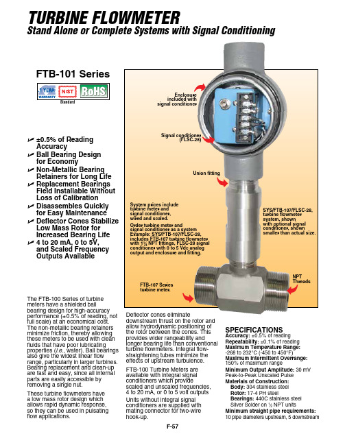
F-57The FTB-100 Series of turbine meters have a shielded ballbearing d esi gn for high-accuracy performance (±0.5% of reading, not full scale) at an economical cost. The non-metallic bearing retainers minimize friction, thereby allowing these meters to be used with clean fluids that have poor lubricatingproperties (i.e., water). Ball bearings also give the widest linear flowrange, particularly in larger turbines. Bearing replacement and clean-up are fast and easy, since all internal parts are easily accessible by removing a single nut.These turbine flowmeters have a low mass rotor design which allows rapid dynamic response, so they can be used in pulsating flow applications.TURBINE FLOWMETERStand Alone or Complete Systems with Signal ConditioningUnion fittingEnclosure with signal conditionerSYS/FTB-107/FLSC-28, turbine flowmeter system, shownwith optional signal conditioner, shownsmaller than actual size.U ±0.5% of Reading Accuracy U B all Bearing Design for Economy U N on-Metallic Bearing Retainers for Long Life U R eplacement Bearings Field Installable Without Loss of Calibration U D isassembles Quickly for Easy Maintenance U D eflector Cones Stabilize Low Mass Rotor for Increased Bearing Life U 4 to 20 mA, 0 to 5V, and Scaled Frequency Outputs AvailableFTB-101 SeriesSPECIFICATIONSAccuracy: ±0.5% of reading Repeatability: ±0.1% of reading Maximum Temperature Range: -268 to 232°C (-450 to 450°F)Maximum Intermittent Overrange: 150% of maximum rangeMinimum Output Amplitude: 30 mV Peak-to-Peak Unscaled Pulse Materials of Construction: Body: 304 stainless steel Rotor: 17-4 PH steelBearings: 440C stainless steel Silver Solder on 1⁄2 NPT unitsMinimum straight pipe requirements: 10 pipe diameters upstream, 5 downstreamsignal conditioner as a system Example: SYS/FTB-107/FLSC-28, includes FTB-107 turbine flowmeter NPT fittings, FLSC-28 signal conditioner with 0 to 5 Vdc analog output and enclosure and fitting.Signal conditioner(FLSC-28)Deflector cones eliminatedownstream thrust on the rotor and allow hydrodynamic positioning of the rotor between the cones. This provides wider rangeability andlonger bearing life than conventional turbine flowmeters. Integral flow-straightening tubes minimize the effects of upstream turbulence.FTB-100 Turbine Meters are available with integral signal conditioners which providescaled and unscaled frequencies, 4 to 20 mA, or 0 to 5 volt outputs Units without integral signal conditioners are supplied with mating connector for two-wire hook-up.F-58FEconomical Ball Bearing Design with NPT End FittingsComes complete with operator’s manual and 10-point NIST calibration certificate for water.Ordering Examples: FTB-101, 1⁄2 NPT turbine meter with standard NIST calibration for 1 cSt viscosity. FTB-106, 1 NPT turbine meter with NIST calibration for 5 cSt viscosity liquid.† Complete systems with signal conditioneravailable, consult sales.F-59OMEGA ® high accuracy integral signal conditioners are designed for direct mounting onto OMEGA FTB-100 and 200 Series turbine meters. The input circuitry of the signal conditioners has beendesigned to receive and condition low level turbine meter signalswhile rejecting unwanted noise and spurious signals. A signal threshold control is provided which allows the user to set the input sensitivity above the ambient noise level, thereby eliminating any false signal on the output. Signalconditioners are available that can provide 4 to 20 mA, 0 to 5V, and scaled frequency pulse outputs that run on unregulated power supplies. Other units which run off 115 Vac provide both an unscaled pulse output and a 0 to 5V or 4 to 20 mA output. A zero and a span potentiometer allow for simple field adjustment of the analog outputs from the signal conditioners.Maximum Input: 120V RMS Electrical Connections: Screw terminalsMaximum Lead Length: 305 m (1000') of 24 gage copper wire for pulse or mA; 30 m (100') for 0 to 5V output. Weight: 2.3 kg (5 lb)SPECIFICATIONSAccuracy: See “To Order” box Temperature Range: 0 to 70°C (32 to 158°F)Pulse Output: TTL/CMOS; open collector for FLSC-51BInput Frequency: 10-1000 Hz, 28 mV P-P; 1000-2500 Hz, 70 mV P-P. Can be used with any OMEGA ® Turbine MeterSignal conditioners are installed at no charge when purchased with turbine meter.Note: The use of explosion-proof heads does not imply that complete assembly is either explosion-proof or intrinsically safe. It is the user’s responsibility to determine the suitability of materials for a given installation.Comes complete with operator’s manual.Ordering Examples: SYS/FTB-101/FLSC-18B , turbine and signal conditioner system, SYS/FTB-201/FLSC-34, turbine and signal conditioner.INTEGRAL SIGNAL CONDITIONERSFor Frequency, Voltage, or Current OutputSignal Conditioner (Enclosure Mounted) OnlyU Up to 0.05% Accuracy U C hoose from Six Output TypesU CMOS/TTL Compatible U A djustable Low Level Signal Filter for Noise RejectionU E xplosion-Resistant Heads U F or FTB-100 and FTB-200 Turbine Flowmeters U I ntegral SignalConditioners Available for 4 to 20 mA, 0 to 5V, and Factored Pulse OutputsFLSC-18B SeriesFLSC-18B shown actual size.。
FLECK 3200系列电动机械计时器水处理系统用户手册说明书
FLECK 3200 SERIES ELECTROMECHANICAL TIMER OWNER’S MANUAL• Greater lathering of soap• Cleaner dishes, towels, and linens• Softer skin2 • FLECK 3200 Series Electromechanical Timer Owner’s ManualMANUAL OVERVIEWHow To Use This ManualThis owner’s manual is designed to provide the equipment owner with instructions on performing routine care and maintenance of the water softener or filter valve and control packaged with this manual.This manual does not include instructions regarding installation, setup, service, or troubleshooting of the valve, control, or other components of a water conditioning system. Please contact your local water treatment professional with questions or concerns about the operation or performance of your water conditioning system.NOTE: This will make the process easier if followed.General Warningsremove or repair individual components.unplug the AC adapter from its power source.(49°C).(38°C).FLECK 3200 Series Electromechanical Timer Owner’s Manual • 33200 ModelSetting the Time of DayTo set the time of day, push the red Time Set button and spin the 24-Hour Gear until the present time of day is above the Time of Day Arrow.Setting the Skipper WheelSet the days that regeneration is to occur by sliding tabs on the skipper wheel outward to expose trip fingers. Each tab represents one day, and the red pointer on the skipper wheel points to the finger representing tonight. Moving clockwise from the pointer, extend or retract fingers to obtain the desired regeneration schedule.Forcing a Manual RegenerationTo manually regenerate the valve, turn the manual regeneration knob clockwise until the valve motor starts to turn.4 • FLECK 3200 Series Electromechanical Timer Owner’s Manual3210 ModelSetting the Time of Day To set the time of day, push the red Time Set button and spin the 24-Hour Gear until the present time of day is above the Time of Day Arrow.Setting the Program Wheel To set the program wheel, lift gallon wheel and rotate it so that the volume of water (gallons or cubic meters) can be treated is aligned with the white dot on the program wheel. Release the dial and check for firm alignment at the setting.Forcing a Manual Regeneration To manually regenerate the valve, turn the manual regeneration knob clockwise until the valve motor starts to turn.continuedFLECK 3200 Series Electromechanical Timer Owner’s Manual • 5BYPASSING THE WATER CONDITIONING SYSTEMA bypass should be installed on all water conditioning systems. A bypass isolates the conditioner from the water system and allows unconditioned water to be used while the conditioner is undergoing service or maintenance procedures or if the conditioner is experiencing performance issues. Figures 1, 2, and 3 show the most common bypass methods.Metal Bypass ValveThis type of bypass is located directly behind the conditioner valve on top of the media tank. To bypass the conditioner system using this type of bypass, turn the handle on top of the bypass until the arrow on the handle is pointing to the word BYPASS stamped on the bypass valve body.To return the conditioner system to regular service, turn the bypass handle until the arrow on the handle is pointing to SERVICE (see Figure 2).Plastic Bypass ValveThis type of bypass is also located directly behind the conditioner valve on top of the media tank. To bypass the conditioner system using this type of bypass, turn both of the small handles on the bypass until they are in the position shown in Figure 3, perpendicular to the inflow and outflow plumbing.To return the conditioner system to regular service, turn both of the small handles on the bypass back to their original positions, parallel with the inflow and outflow plumbing.Manual BypassThis type of bypass system is plumbed into the pipes of the water system, and generally consists of three valves: one on the inflow line going into the conditioning system, one on the outflow line coming out of the conditioning system, and one on the bypass line connecting the inflow and outflow lines (See Figure 4).To bypass the conditioner system using this type of bypass (following Figure 4), open Valve 2 and close Valves 1 and 3.To return the conditioner system to regular service, open Valves 1 and 3 and close Valve 2.Figure 1 Metal Bypass Valve Figure 3 Manual Bypass6 • FLECK 3200 Series Electromechanical Timer Owner’s ManualTROUBLESHOOTINGProblemSolution Control valve fails to regenerate Check for power outage and verify unit is plugged in. Attempt to perform a manual regeneration. See “SETTING TIME OF DAY AND INITIATING A MANUAL REGENERATION”. If problem still exists, contact your local water treatment professional.Water does not feel or appear softCheck salt in brine tank and ensure salt level is above water level. If problem still exists, contact your local water treatment professional.Unit uses too much saltContact your local water treatment professional.Loss of water pressureIron in conditioned waterExcessive water in brine tankOther problems with the water softenerPower Outage Reset the Time of Day in the event of a power outage/failure. See “SETTING TIME OF DAY AND INITIATING A MANUAL REGENERATION”.CARE AND USE OF YOUR BRINE TANKEach time the softener regenerates, salty water (brine) is needed to recondition the media in the water tank. The brine is pulled from the salt tank at a controlled amount. If the salt tank does not contain enough salt, the brine is weak, the media will not fully recondition and untreated water will pass through. To ensure the highest level of performance of your water conditioning system, please observe the following:• Keep the brine tank filled with salt at all times. The salt level should always be higher than the water level in the brine tank.• Only use salt designed for water softeners. Other types of salt (rock or snow melting) may contain dirt and chemicals that will affect the quality of your water and the performance of your water softener. • Keep the brine tank covered.• Empty and clean the tank every three years.FLECK 3200 Series Electromechanical Timer Owner’s Manual • 7All Pentair trademarks and logos are owned by Pentair, Inc. or its affiliates. All other registered and unregistered trademarks and logos are the property of their respective owners. Because we are continuously improving our products and services. Pentair reserves the right to change specifications without prior notice. Pentair is an equal opportunity employer.44051 REV A JA16 © 2016 Pentair Residential Filtration, LLC All Rights Reserved.For product warranties, complete service manuals, and additional resources visit: DEALER STAMP。
FLB-100说明书
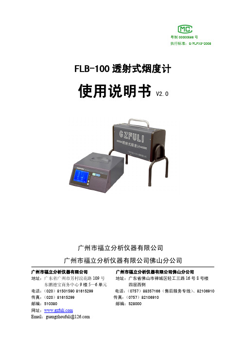
■结构与作用
FLB-100 透射式烟度计主要由两大部分组成:检测平台、显示仪。
1. 检测平台
图1 .4.
如图 1, 检测平台负责完成对压燃式发动机和装有压燃式发动机的车辆排气可见污染物的检测 并回送检测结果给显示仪。检测平台对排气可见污染物进行连续测量,动态反映排气污染物的变 化,可准确测量出各种排烟的不透光度 N 和光吸收系数 k。
注意: 检查或连接电源线和通讯线过程中应断开电源, 以免 损坏仪器或人遭到伤害。 3. 预热 仪器接通电源后,先进行预热(如图 4) 。预热是为保证测量结果的准确性。不同的环境温度, 预热时间有所不同,当显示仪显示的管温达到 80℃时,则表示仪器已经完成预热,可进入测量, 若要求测量数据的稳定性更好,可适当延长预热时间( 即使完成正常预热时间也不要马上进入测 量)30 分钟。
图7 在【测量】界面、 【稳态】界面或【加速】界面期间按“功能”键均可进入【菜单】界面, 【菜 单】界面主要用来指导用户进行【线性校正】 (零位校准) 、 【线性检查】 、 【通讯设置】 、 【时钟设置】 等操作。 前面板按键功能: “确认”键——按下该键表示执行或确认当前选择; “功能”键——按下该键退出当前界面,或返回【菜单】界面; “ “ “ ”键——该键用作移位键,其它功用根据各界面提示; ”键——该键用作移位键或修改键,其它功用根据各界面提示; ”键——该键用于调节显示屏亮度。
01h取状态码02h取测量值03h取稳态值04h取加速值05h请求进行线性校正06h设置仪器为直接测量状态07h设置仪器为稳态测量状态08h设置仪器为加速测量状态09h请求停止稳态测量0ah请求开始稳态测量0bh请求进行一次加速触发自动触发0eh请求取最近一次加速主数据0fh请求取最近一次加速曲线数据取状态码命令01h令
FB-100 子波音频系统操作指南说明书

OPERATING INSTRUCTIONS SUB-WOOFER SYSTEM FB-100 Please follow the instructions in this manual to obtain optimum results from this unit.We also recommend that you keep this manual handy for future reference.TABLE OF CONTENTS1.SAFETY PRECAUTIONS (2)2.GENERAL DESCRIPTION (3)3.FEATURES (3)4.HANDLING PRECAUTIONS (3)5.NOMENCLATURE (3)6.CONNECTIONS (4)7.MATCHING TRANSFORMER INSTALLATION (4)8.CROSSOVER CONNECTIONS WITH A FULL-RANGE SPEAKER8.1.Recommended Filters for the FB-100 (5)8.2.Level Balance and Polarity8.2.1. Level balance adjustment (6)8.2.2. Polarity adjustment (6)9.CAUTIONS CONCERNING HIGH-IMPEDANCE APPLICATIONS (6)10.INSTALLATION10.1.Installation Locations (7)10.2.Unit Suspension (7)11.SPECIFICATIONS (8)2When Installing the Unit•Install the unit only in a location that can structurally support the weight of the unit and the mounting bracket. Doing otherwise may result in the unit falling down and causing personal injury and/or property damage.•Do not use other methods than specified to mount the bracket. Extreme force is applied to the unit and the unit could fall off, possibly resulting in personal injuries.•Use proper nuts and bolts when hanging the speaker. If improper nuts and bolts are used, the speaker could fall off, resulting in personal injury. •Tighten each nut and bolt securely. Ensure that the bracket has no loose joints after installation to prevent accidents that could result in personal injury.When the Unit is in Use•Do not operate the unit for an extended period of time with the sound distorting. This is an indication of a malfunction, which in turn can cause heat to generate and result in a fire.1. SAFETY PRECAUTIONS•Be sure to read the instructions in this section carefully before use.•Make sure to observe the instructions in this manual as the conventions of safety symbols and messages regarded as very important precautions are included.•We also recommend you keep this instruction manual handy for future reference.Safety Symbol and Message ConventionsSafety symbols and messages described below are used in this manual to prevent bodily injury and property damage which could result from mishandling. Before operating your product, read this manual first and understand the safety symbols and messages so you are thoroughly aware of the potential safety hazards.2. GENERAL DESCRIPTIONThe TOA FB-100 is a high-power sub-woofer system employing a 25 cm speaker unit designed to withstand large, low-frequency voice-coil movement. Although small in size, the FB-100 provides clear super-low frequency sound reproduction thanks to its Acoustic Super Woofer enclosure construction.3. FEATURES•A large, 120 mm-diameter ferrite magnet, a long, 50 mm-diameter voice coil, an aluminum bobbin, a non-pressed paper cone, and a large-diameter damper combine to permit large voice coil movement at high power input.•The Acoustic Super Woofer system enclosure creates an acoustic band-pass filter that reproduces super-low frequencies down to 35 Hz and realizes slow-slope phase characteristics.•The speaker can be converted to high-impedance applications with the addition of the optional MT-S0610 matching transformer.•The urethane-painted enclosure is made of Medium Density Fiberboard (MDF) and can be easily repainted.•Six external mounting screws are positioned along the sides of the enclosure to facilitate cable-suspended installations.•The unit's removable top panel facilitates maintenance work after installation.4. HANDLING PRECAUTIONSNo anti-magnetic provisions have been made for the FB-100 speaker. Therefore, take care to keep the unit sufficiently away from televisions, monitors or computer-related equipment.5. NOMENCLATURE[Top] [Front] [Bottom]EnclosureUnit: mm346. CONNECTIONSNote:The FB-100's input connector is of detachable type.Step 1.Detach the input connector from theconnector socket.Step ing a screwdriver, loosen the screws ofthe terminals to use. Connect stripped cable ends to the terminals, then retighten the terminal screws.Tips• Usable cable: Solid cable or stranded cable (0.2mm 2- 2.5 mm 2) (Corresponding to AWG No. 24 - 14)• Strip the insulation back about 5 mm from the cable ends.[When bridging no terminals]Step 3.Insert the input connector into the unit.7. MATCHING TRANSFORMER INSTALLATIONAn optional MT-S0601 matching transformer can be installed in the FB-100 speaker.Step 1.Remove 7 screws to detach the enclosuretop panel.Step 2.Remove 2 transformer mounting screwslocated close to the connector circuit ing the 2 screws, mount the MT-S0601transformer with its connection lug (impedance tap) side up.MT-S0601Transformer mounting screwTighten the screws of idleterminals as well to prevent resonance noise.5Step 3.Disconnect the junction connector of a leadwire coming from the connector circuit board. (Widen the lock tab to pull theStep 4.Connect the MT-S0601's two connectors tothe junction connectors disconnected in Step 3.Step 5.Connect the speaker input cable to thedesired transformer lug to set the impedance.Step 6.Replace the top panel and retighten the 7screws.Step 7.Affix the impedance label supplied with theMT-S0601 to over the FB-100's nameplate as shown below to indicate the selected transformer impedance.8. CROSSOVER CONNECTIONS WITH A FULL-RANGE SPEAKER8.1. Recommended Filters for the FB-100•filtering.•signal to the sub-woofer.•digital signal processor for the FB-100's signal system:High-pass filter (–12 dB/oct):Cut-off frequency = 40 Hz, Q = 1.0Low-pass filter (–12 dB/oct):Cut-off frequency = 100 Hz, Q = 1.0RedWhiteMT-S06018.2. Level Balance and PolarityWhen using the FB-100 in combination with TOA's F or H Series Full-Range Speakers, adjust their level balance or polarity depending on the conditions of the installation location.8.2.1. Level balance adjustmentAdjust the level of the sub-woofer or full-range speaker depending on the number of units to be installed or installation conditions.8.2.2. Polarity adjustment•Acoustic energy increases at the crossover band for the sub-woofer and full-range speaker if the two speakers are in phase with each other, and decreases if out of phase. Because the phase characteristics of both the sub-woofer and the full-range speaker vary continuously depending on frequency, simply matching the connector polarities of the sub-woofer is not always the best procedure.•To confirm how much the acoustic energy increases or decreases, reverse the polarity of the sub-woofer's "+" and "–" connectors and select the connection polarity that results in the largest output of acoustic energy. (The use of a real-time spectrum analyzer to check the degree of energy increase is highly recommended.)9. CAUTIONS CONCERNING HIGH-IMPEDANCE APPLICATIONSTo avoid damaging the FB-100 speaker in high-impedance applications (with the MT-S0601 matching transformer installed), be sure to observe the following conditions.1. Do not limit the input signal band using such devices as a low-pass filter, but instead drive the speaker withthe full-range signal.2. Use a high-impedance amplifier with a power rating higher than the wattage tap selected on the matchingtransformer.TipThere is a low-frequency threshold for both the speaker matching transformer and the high-impedance amplifier output transformer.[Matching transformer low-frequency threshold]If a signal with the frequencies lower than the low-frequency threshold is applied at rated power, the transformer's primary impedance (input impedance) decreases abruptly due to core magnetic saturation. With the MT-S0601, the impedance begins to decrease at approximately 40 Hz for the rated input power of 60 W, and is almost halved at 30 Hz. If the speaker is used under this condition, an increased load is put on the power amplifier as well as the matching transformer, causing potential equipment damage.The low-frequency threshold varies depending on the selected transformer tap, and the smaller the tap-selected wattage, the lower the threshold.[High-impedance amplifier low-frequency threshold]When a full-range signal (not band-limited) is applied, the amplifier is not adversely affected.However, if the signal is band-limited with a low-pass filter and driven with rated power, an increased load is put on the output stage, causing potential amplifier damage.610. INSTALLATION10.1. Installation LocationsBy installing the FB-100 speaker close to the ceiling, wall or floor, the speaker's sound energy radiationNoteDo not block the opening of a port.10.2. Unit Suspensionconjunction with eyebolts, the FB-100 can be hung as illustrated.Notewhen using the mounting screws to fix or hang the unit.711. SPECIFICATIONSEnclosure Acoustic Super Woofer systemPower Handling Capacity Continuous program:450 WContinuous pink noise:150 W (40 – 200 Hz, 24 hours)Rated Impedance 8 ΩOutput Sound Pressure94 dB (1 W, 1 m), installation in 1/2 free sound fieldLevel88 dB (1 W, 1 m), installation in free sound fieldFrequency Response35 – 160 Hz (–10 dB, installation in 1/2 free sound fieldInternal Speaker 25 cm cone typeInput Terminals Detachable screw terminals, (+)/(–): 2 each (for bridge connection)Usable Cable Solid or twisted cable: 0.2 - 2.5 mm2(corresponding to AWG24-14)Finish Urethane-painted Medium Density Fiberboard (MDF), blackDimensions 345 (w) x 582 (h) x 340 (d) mm (projections excluded)Weight 16 kgNote:The unit's specifications and external design are subject to change without notice for improvement.• Optional equipmentMatching transformer MT-S0601 (rated at 60 W)Printed in Japan133-01-424-4A。
FISHER WB-100B 步行式播药机器人说明书

WB-100BWalk-Behind Broadcast Spreader Owner's Manual and Installation InstructionsOriginal InstructionsThis document is for FISHER® WB-100B walk-behind broadcast spreaderswith serial numbers beginning with 0000 and higher.TABLE OF CONTENTSPREFACE (5)Owner's Information Form (5)SAFETY (6)LOADING (8)ASSEMBLY (9)PREFACEThis manual has been prepared to acquaint you with the safety information, operation, and maintenance of your new walk-behind spreader. Please read this manual carefully and follow all recommendations. This will help ensure pro fi table and trouble-free operation of your spreader. Keep this manual accessible. It is a handy reference in case minor service is required.Register your spreader online at www.fi OWNER'S INFORMATIONOwner's Name: _______________________________________________________________________Date Purchased: ______________________________________________________________________Outlet Name: ______________________________________________ Phone: ___________________Outlet Address: _______________________________________________________________________Spreader Type (Model): ________________________________ Weight: ____________________lb/kg Spreader Serial Number:________________________________________________________________When service is necessary, bring your walk-behind spreader to your distributor. They know your spreader best and are interested in your complete satisfaction.SAFETY DEFINITIONSNOTE: Indicates a situation or action that can lead to damage to your spreader and vehicle or other property. Other useful information can also be described.LABELSPlease become familiar with the labels on the spreader.NOTE: If labels are missing or cannot be read, seeyour sales outlet.Open/Close LabelSerial Number LabelCode De fi nition MM 2-Digit Month YY 2-Digit YearLL 2-Digit Location Code ####4-Digit Sequential Number PPPPP5-Digit Assembly PNSAFETY PRECAUTIONSImproper installation and operation could cause personal injury and/or equipment and property damage. Read and understand labels and this Owner's Manual before assembling, operating, or making adjustments.NOTE: Lubricate grease fi ttings after each use. Use a good quality multipurpose grease. PERSONAL SAFETY• Wear only snug-fi tting clothing while working on your spreader.• Do not wear jewelry or a necktie, and secure long hair.• Wear safety goggles to protect your eyes from dirt and dust.NOISEAirborne noise emission during use is below 70 dB(A) for the spreader operator.VIBRATIONOperating spreader vibration does not exceed 2.5 m/s2 to the hand-arm or 0.5 m/s2 to the whole body.LOADING YOUR SPREADER Material WeightsMaterial Density (lb/ft3)Rock Salt80–90SPREADING TIPS• Use care when operating spreader nearpedestrians.• Spread ice melting materials "with the storm" to prevent unmanageable levels of ice from building up.• For a wider pass, increase pace.• For a heavier pass, decrease pace. ACCESSORIESA Poly Defl ector Kit accessory (PDK-020) is available from your distributor. It provides a tighter spread pattern for areas such as sidewalks and walkways.5. Slide the handle assembly on to the frame standand fasten with two 1/4" x 1-3/8" cap screws and 1/4" locknuts.ASSEMBLING YOUR SPREADER1. The spreader is shipped with tires partially in fl ated. Using a manual pump, fully in fl ate the tires to the psi setting shown on the tire sidewall.2. Feed the gate actuator rod through the keyholeslot in the frame stand.3. Move the gate handle to the fully open position.4. Insert the upper end of the gate actuator rod intothe gate handle.Gate Actuator RodGate Handle6. Insert the gate actuator rod end into the gate camand secure with a hairpin cotter.7. Spin the tires and make sure the spreader isrunning smoothly.8. Tighten all fasteners.9. Place the screen inside the hopper and put thehopper cover on.MAINTENANCELUBRICATIONTo keep your spreader running smoothly, observe thefollowing recommendations:Remove the gearhousing and applychain lube spraylubricant.multipurpose grease.NOTE: Gears and axles must be lubricated andgreased every 20 hours of use.Fisher Engineering50 Gordon DriveRockland, ME 04841-2139www.fi A DIVISION OF FISHER, LLCThis product conforms to EU Machinery Directive 2006/42/EC.Copyright © 2019 Douglas Dynamics, LLC. All rights reserved. This material may not be reproduced or copied, in whole or in part, in any printed, mechanical, electronic, fi lm, or other distribution and storage media, without the written consent of Fisher Engineering. Authorization to photocopy items for internal or personal use by Fisher Engineering outlets or spreader owner is granted.Fisher Engineering reserves the right under its product improvement policy to change construction or design details and furnish equipment when so altered without reference to illustrations or specifi cations used. Fisher Engineering offers a limited warranty for all spreaders and accessories. See separately printed page for this important information. The following is a registered (®) trademark of Douglas Dynamics, LLC: FISHER®.Printed in U.S.A.。
L-25OMEGAFLEX OEM StyLE 粒子泵系列 FPU100 产品说明书
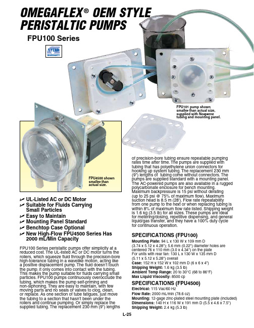
OMEGAFLEX ®OEM StyLE PEriStALtic PuMPSFPU100 SeriesU UL-Listed AC or DC Motor U S uitable for Fluids Carrying Small Particles U Easy to MaintainU Mounting Panel Standard U Benchtop Case Optional U N ew High-Flow FPU4500 Series Has 2000 mL/Min CapacityFPU100 Series peristaltic pumps offer simplicity at a reduced cost. The UL-listed AC or DC motor turns the rollers, which squeeze fluid through the precision-bore high-tolerance tubing in a wavelike motion, acting like a positive displacement pump. The fluid doesn’t touch the pump; it only comes into contact with the tubing. This makes the pump suitable for fluids carrying small particles. FPU100 pumps continuously overocclude the tubing, which makes the pump self-priming and non-siphoning. They are easy to maintain, with few moving parts and no seals or valves to clog, clean, or replace. As one section of tube fatigues, just move the tubing to a section that hasn’t been under the rollers and continue pumping. Or simply replace the supplied tubing. The replacement 230 mm (9") lengthsof precision-bore tubing ensure repeatable pumping rates time after time. The pumps are supplied with tubing that has polyethylene union connectors for hooking up system tubing. The replacement 230 mm (9") lengths of tubing come without connectors. The pumps are supplied standard with a mounting panel. The AC-powered pumps are also available in a rugged polycarbonate enclosure for bench mounting. Maximum backpressure is 15 psi without derating (up to 25 psi @ 75% of maximum flow). Maximum suction head is 8.5 m (28'). Flow rate repeatability from one pump to the next or when replacing tubing is within 8% of maximum flow rate listed. Shipping weight is 1.6 kg (3.5 lb) for all sizes. These pumps are ideal for metering/dosing, repetitive dispensing, and general liquid/gas transfer, and they have a 100% duty cycle for continuous operation.SPECiFiCAtiONS (FPU100)Mounting Plate: 94 L x 130 W x 109 mm D(3.74 x 5.12 x 4.28"); 5.6 mm (0.22") diameter holes are centered 76 x 110 mm (3.0 x 4.34") on the plate For units with rear fan: 130 L x 130 W x 135 mm D (5.11 x 5.12 x 5.28") overallCase: 152 H x 152 W x 102 mm D (6 x 6 x 4")Shipping Weight: 1.6 kg (3.5 lb)Ambient temp Range: 20 to 30°C (68 to 86°F)Max Liquid Viscosity: 8500 cpSPECiFiCAtiONS (FPU4500)Electrical: 115 Vac/60 HzFlow Rate: 2000 mL/min (78.6 oz)Mounting: 12-gage zinc-plated steel mounting plate (included)Dimensions: 140 H x 116 W x 191 mm D (5.5 x 4.6 x 7.5")Shipping Weight: 2.4 kg (5.3 lb)FPU101 pump shown smaller than actual size, supplied with Norprenetubing and mounting panel.FPU4500 shown smaller thanactual size.LBenchtop Case AvailableThe AC-powered pumps are also available in a rugged polycarbonate enclosure with on/off switch, power indicator lamp, and rubber feet for benchtop use. Each is supplied with a 1.8 m (6'), 115 Vac, 3-wire cord. To order, select the desired pump. Add suffix “-CASE ” to model number for additional cost. For 240 Vac models with European plug, consult OMEGA’s Flow Department. An optional 24-hour timer with momentary “on” switch for priming the pump is also available for the case unit. The timer is settable up to 24 hours inincrements of 15 minutes by internal DIP switches. To order case unit with timer for 115 Vac, add suffix “-CASE-Ct ” to model number, for additional cost.168tubes. Connection is made to the 1⁄16 x 1⁄8"internal tubing. Brushless 115 Vac,60 Hz induction motors; flow rates based on pumping water.Replacement* The FPU4500 comes with Norprene tubing (not available as a case unit with timer).(FPU100 Series)**240 Vac amperage is 1⁄2 that for 115 Vac; for 24 Vdc power, 0.8 A nominal max. For dual-head units, consult OMEGA’s Flow Engineering Department.† Pumps are supplied with Norprene tubes standard. For silicone tubing, add suffix “-SL ” to model number, no additional charge.Note: DC-powered versions have a 500 hr life; for long-term or continuous applications, use the standard 115 Vac powered models.For units powered by 12 or 24 Vdc, add suffix “-12VDC” or “-24VDC” to the model number, for additional cost.For units powered by 240 Vac @ 50 Hz, add suffix “-240VAC ” to model number, for additional cost. 50 Hz units have approximately 5⁄6 of the capacity of standard 60 Hz units.For dual head units with 2 separate outputs, add suffix “-DUAL ” to model number, for additional cost, for FPU101 through FPU120. For FPU121 through 125-DUAL , for additional cost.Ordering Examples: FPU119-240VAC-DUAL , 240 Vac, 50 Hz powered, dual-head unit with a total flow of 5⁄6 x 2000 mL/min = 1666 mL/min.FPU109-SL , 50 mL/min pump with silicone tube.FPU107-CASE , pump with polycarbonate enclosure.FPU111-CASE shown smaller than actual size.†。
Milestone AV Technologies FLR100 侧面扬声器辅助设备说明书
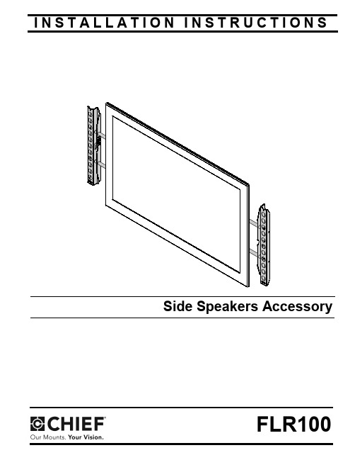
I N S T A L L A T I O N I N S T R U C T I O N SSide Speakers AccessoryFLR100FLR100Installation Instructions2DISCLAIMERMilestone AV Technologies and its affiliated corporations and subsidiaries (collectively "Milestone"), intend to make thismanual accurate and complete. However, Milestone makes no claim that the information contained herein covers all details,conditions or variations, nor does it provide for every possible contingency in connection with the installation or use of this product. The information contained in this document is subject to change without notice or obligation of any kind. Milestone makes no representation of warranty, expressed or implied,regarding the information contained herein. Milestone assumes no responsibility for accuracy, completeness or sufficiency of the information contained in this document.Chief® is a registered trademark of Milestone AV Technologies.All rights reserved.IMPORTANT WARNINGS AND CAUTIONS!WARNING: A WARNING alerts you to the possibility ofserious injury or death if you do not follow the instructions.CAUTION: A CAUTION alerts you to the possibility ofdamage or destruction of equipment if you do not follow the corresponding instructions.WARNING:Failure to read, thoroughly understand, andfollow all instructions can result in serious personal injury,damage to equipment, or voiding of factory warranty! It is the installer’s responsibility to make sure all components are properly assembled and installed using the instructions provided.WARNING:Failure to provide adequate structural strengthfor this component can result in serious personal injury or damage to equipment! It is the installer’s responsibility to make sure the structure to which this component is attached can support five times the combined weight of all equipment.Reinforce the structure as required before installing the component.WARNING:Exceeding the weight capacity can result inserious personal injury or damage to equipment! It is the installer’s responsibility to make sure the combined weight of all components located on the FLR100 does not exceed 20 lbs (9.1 kg) on each side.LEGENDApretar elemento de fijación Befestigungsteil festziehen Apertar fixador Serrare il fissaggio Bevestiging vastdraaien Serrez les fixations Aflojar elemento de fijación Befestigungsteil lösen Desapertar fixador Allentare il fissaggio Bevestiging losdraaien Desserrez les fixations Llave de boca Gabelschlüssel Chave de bocas Chiave a punte aperte Steeksleutel Clé à fourcheMarcar con lápiz Stiftmarkierung Marcar com lápis Segno a matita Potloodmerkteken Marquage au crayon Destornillador Phillips Kreuzschlitzschraubendreher Chave de fendas Phillips Cacciavite a stella Kruiskopschroevendraaier Tournevis à pointe cruciforme Adjust Ajustar Einstellen Ajustar Regolare Afstellen AjusterInstallation Instructions FLR100 DIMENSIONS3FLR100Installation Instructions TOOLS REQUIRED FOR INSTALLATION#21/2"PARTS45Figure 12.Install and tighten the knob (G) on each speaker extension.(See Figure 2)order to tighten the side speaker bushings.Figure 3FLR100Installation Instructions6Attaching Speakers and Brackets1.Attach speakers (not included) to speaker brackets (C)following instructions included with speakers.2.Loosely attach one 1/4-20 x 1/2" hex head cap screw (D),one 1/4" lock washer (E) and one 1/4" flat washer (F) to top of each of the speaker brackets (C). (See Figure 4)3.Hang speaker brackets (with attached speakers) on the left and right speaker extensions, and loosely attach bottom of speaker brackets (C) to speaker extensions using one1/4-20 x 1/2" hex head cap screw (D), one 1/4" lock washer (E) and one1/4" flat washer (F) on each speaker extension.(See Figure 4)Figure 44.Push speakers into desired position by lifting slightly on speakers to enable them to slide more easily.5.Adjust and level speaker brackets (C) using lower slot. (See Figure 4)6.Tighten all four fasteners.7.Turn knob (G) outward on both left and right speaker brackets until the knob contacts the wall. This will allow vertical leveling of the speakers.Installation Instructions FLR1007FLR100Installation InstructionsUSA/InternationalA 8401 Eagle Creek Parkway, Savage, MN 55378P 800.582.6480 / 952.894.6280F 877.894.6918 / 952.894.6918EuropeA Fellenoord 130 5611 ZB EINDHOVEN, The Netherlands P +31 (0)40 2668620F +31 (0)40 2668615Asia PacificARoom 24F, Block D, Lily YinDu International BuildingLuoGang, BuJi Town, Shenzhen, CHINA.P +86-755-8996 9226F +86-755-8996 9217Chief Manufacturing, a products division of Milestone AV Technologies 8807-0000832009 Milestone AV Technologies, a Duchossois Group Company 01/09。
福立FLB-100通讯协议
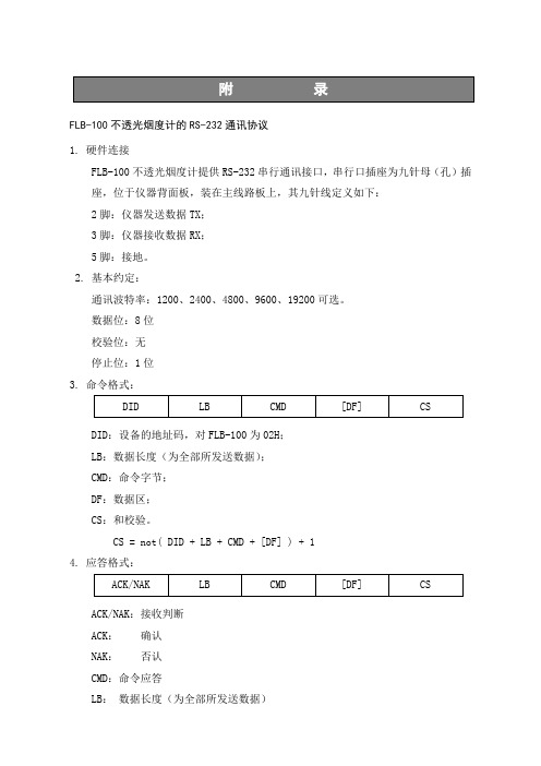
FLB-100不透光烟度计的RS-232通讯协议1. 硬件连接FLB-100不透光烟度计提供RS-232串行通讯接口,串行口插座为九针母(孔)插座,位于仪器背面板,装在主线路板上,其九针线定义如下:2脚:仪器发送数据TX;3脚:仪器接收数据RX;5脚:接地。
2. 基本约定:通讯波特率:1200、2400、4800、9600、19200可选。
数据位:8位校验位:无停止位:1位3. 命令格式:DID:设备的地址码,对FLB-100为02H;LB:数据长度(为全部所发送数据);CMD:命令字节;DF:数据区;CS:和校验。
CS = not( DID + LB + CMD + [DF] ) + 14. 应答格式:ACK/NAK:接收判断ACK:确认NAK:否认CMD:命令应答LB:数据长度(为全部所发送数据)DF:数据区CS:校验和CS=not(ACK/NAK+LB+CMD+[DF])+15. 响应:⑴没响应信号在述情况下,没有响应信号:▲设备地址码不符▲校验和不符▲启动通讯超过3秒,但仪器未完成动作▲仪器非正常状态⑵ ACK应答:仪器接收到正确的命令,将回送ACK作为响应,下述情况将回送ACK:▲命令码正确▲命令参数设置正确(紧跟命令之后的数据格式必须正确)▲仪器接收到所允许的设备地址码和命令⑶ NAK响应主机命令不正确、命令参数设置不正确,不能满足响应ACK条件,则响应NAK。
6. 命令代码表⑴取状态码命令01H命令:01H命令格式:02H—04H—01H—f9H响应格式:ACK:06H—07H—01H—状态码1—状态码2—状态码3—校验和;NAK:15H状态码描述:状态码1状态码2状态码3⑵取测量值命令02H命令:02H命令格式:02H—04H—02H—f8H响应格式:ACK:06H—0dH—02H—K值高位—K值低位—Ns值高位--Ns值低位—气温—油温高位—油温低位—转速高位—转速低位—校验和;NAK:15H⑶取稳态值命令03H命令:03H命令格式:02H—04H—03H—f7H响应格式:ACK:06H—0cH—03H—Km值高位—Km值低位—Nm值高位--Nm值低位—Tm高位—Tm低位—油温高位—油温低位—校验和;NAK:15H⑷取加速值命令04H命令:04H命令格式:02H—04H—04H—f6H响应格式:没有加速值时(加速测量不成功):ACK:06H—07H—04H—00H—00H—00H—efH仪器处于加速过程中:ACK:06H—05H—04H—0fH—e2H有加速值时:ACK:06H—0eH—04H—K平均值高位—K平均值低位—Kn高位—Kn低位—Kn-1高位—Kn-1低位—Kn-2高位—Kn-2低位—校验和;NAK:15H⑸请求进行线性校正命令05H命令:05H命令格式:02H—04H—05H—f5H响应格式:ACK:06H—04H—05H—f1HNAK:15H⑹设置仪器为直接测量状态命令06H命令:06H命令格式:02H—04H—06H—f4H响应格式:ACK:06H—04H—06H—f0HNAK:15H⑺设置仪器为稳态测量状态命令07H命令:07H命令格式:02H—04H—07H—f3H响应格式:ACK:06H—04H—07H—efHNAK:15H⑻设置仪器为加速测量状态命令08H命令:08H命令格式:02H—04H—08H—f2H响应格式:ACK:06H—04H—08H—eeHNAK:15H⑼请求停止稳态测量命令09H命令:09H命令格式:02H—04H—09H—f1H响应格式:ACK:06H—04H—09H—edHNAK:15H⑽请求开始稳态测量命令0aH命令:0aH命令格式:02H—04H—0aH—f0H响应格式:ACK:06H—04H—0aH—ecHNAK:15H⑾请求进行一次加速触发(自动触发)命令0bH命令:0bH命令格式:02H—04H—0bH—efH响应格式:ACK:06H—04H—0bH—ebHNAK:15H⑿请求取最近一次加速主数据0eH命令:0eH命令格式:02H—04H—0eH—ecH响应格式:ACK:06H—08H—0eH—Km值高位--Km值低位—转速高位—转速低位—校验和;NAK:15H⒀请求取最近一次加速曲线数据命令0fH命令:0fH命令格式:02H—04H—0fH—ebH响应格式:ACK:06H—ceH—0fH—N1高位—N1低位……N100高位—N100低位—转速高位—转速低位—校验和;NAK:15H说明:N1—N100是一条100点曲线的N值,转速为此次加速过程中的最大转速。
Omega FPB100系列流量传感器说明书
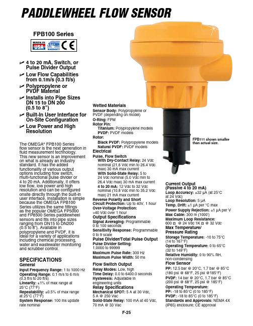
F-25Paddlewheel Flow SenSorU 4 to 20 mA, Switch, or Pulse Divider OutputU Low Flow Capabilities from 0.1m/s (0.3 ft/s)U Polypropylene or PVDF MaterialU Installs into Pipe Sizes DN 15 to DN 200 (0.5 to 8")U Built-In User Interface for On-Site ConfigurationU Low Power and High ResolutionThe OMEGA ®FPB100 Seriesflow sensor is the next generation in fluid measurement technology. This new sensor is an improvement on what is already an industry standard. It has the added functionality of various output options including flow switch, multi-functional pulse divider or 4 to 20 mA. Additionally, it offers low flow, low power and high resolution and can be configured onsite directly through the built-in user interface. Installation is simple because the OMEGA FPB100 Series utilizes the same fittings as the popular OMEGA FP5000 and FP8500 Series paddlewheel sensors and fits into pipe sizes ranging from DN15 to DN200 (0.5 to 8”). Available in polypropylene and PVDF, it is ideal for a variety of applications including chemical processing, water and wastewater monitoring and scrubber control.SPeCIFICAtIONS GeneralInput Frequency Range: 1 to 1000 HzOperating Range: 0.1 m/s to 6 m/s(0.3 ft/s to 20 ft/s)Linearity: ±1% of max range at25°C (77°F)Repeatability: ±0.5% of max rangeat 25°C (77°F)System Response: 100 ms update rate nominal FPB100 SeriesWetted Materials Sensor Body: Polypropylene or PVDF (depending on model)O-Ring: FPM Rotor Pin: titanium: Polypropylene models PVDF: PVDF models Rotor: Black PVDF: Polypropylene models Natural PVDF: PVDF models electrical Pulse, Flow Switch W ith Dry-Contact Relay: 24 Vdc nominal (21.6 Vdc min to 26.4 Vdc max) 30 mA max current W ith Solid-State Relay: 5 to 24 Vdc nominal (5.0 Vdc min to 26.4 Vdc max) 30 mA max current 4 to 20 mA: 12 Vdc to 32 Vdc nominal (10.8 Vdc min to 35.2 Vdc max) 21 mA max current Reverse Polarity and Short Circuit Protection: Up to 40V, 1 hour Over-Voltage Protection: >40 Vdc over 1 hour Output Specifications Signal Averaging: Programmable 0 to 100 seconds Sensitivity Response: Programmable 0 to 9 scale Pulse Divider/total Pulse Output Pulse Divider Setting: 1.0000 to 99999Maximum Pulse Rate: 300 Hz Maximum Pulse Width: 50 ms Flow Switch Output Relay Modes: Low, high time Delay: 0.0 to 6400.0 seconds Hysteresis: Adjustable in engineering units Relay Specifications Mechanical SPDt: 5 A at 30 Vdc, 5 A @ 250 Vac Solid-State Relay: 100 mA at 40 Vdc, 70 mA @ 33 Vac Current Output (Passive 4 to 20 mA) Loop Accuracy: ±32 µA (at 25°C at 24 Vdc) Loop Resolution: 5 µA temp. Drift: ±1 µA per °C max Power Supply Rejection: ±1 µA per V Max Cable: 300 m (1000’)Maximum Loop Resistance: 600 Ω @ 24 Vdc 1K Ω @ 32 Vdc Max temperature/ Pressure Rating Storage temperature: -10 to 75°C (14 to 167°F)Operating temperature: 0 to 65°C (32 to 149°F)Relative Humidity: 0 to 90% RH, non-condensing Flow Sensor PP: 12.5 bar @ 20°C, 1.7 bar @ 85°C (180 psi @ 68°F, 25 psi @185°F)PVDF: 14 bar @ 20°C, 1.7 bar @ 85°C (200 psi @ 68°F, 25 psi @ 185°F)Operating temperature:PP: -18 to 85°C (0 to 185°F)PVDF: -18 to 85°C (0 to 185°F)Standards and Approvals: NEMA 4X(IP65) enclosure; CE approval FPB111 shown smaller than actual size.F-26F130(5)94(3.7)Ordering examples: FPB111, flow sensor with pulse divider output, with FP-5310M, 1" PVC installation fitting, PSU-93, 24 Vdc power supply, and TX4-100, multi-conductor hook-up wire. FPB131, sensor with switch, SPDT, mechanical relay, FP-5320GI galvanized iron fitting, PSU-93 power supply.FMG-5310FP-5320GI FP-5307CUFP-5310M。
环保检测设备配置

第一章设备配置
一、新建站设备配置
(一)轻型车
1.轻型汽油车简易瞬态VMAS工况法检测系统必配清单
备注:用户自配空气压缩机,UPS不间断稳压电源等辅助设备。
2.轻型柴油车LUG—DOWN工况法用配件清单
备注:用户自配空气压缩机,UPS不间断稳压电源等辅助设备。
3.轻型车柴油汽油一体VMAS / ASM / LUGDOWN简易工况法检测系统必配清单
备注:用户自配通讯线缆,UPS不间断稳压电源等辅助设备。
(二)重型车
1.重型单轴汽油车简易瞬态VMAS工况法检测系统必配清单
备注:用户自配通讯线缆,UPS不间断稳压电源等辅助设备。
2.重型单轴柴油车LUG-DOWN工况法用配件清单
备注:用户自配空气压缩机,UPS不间断稳压电源等辅助设备.
3.重型单轴车柴油汽油一体VMAS / ASM / LUGDOWN简易工况法检测系统必配清单
备注:用户自配空气压缩机,UPS不间断稳压电源等辅助设备.
6.重型多轴车柴油LUGDOWN简易工况法检测系统必配清单
合计:40。
9万
备注:用户自配空气压缩机,UPS不间断稳压电源等辅助设备。
二、新建站联网方案。
- 1、下载文档前请自行甄别文档内容的完整性,平台不提供额外的编辑、内容补充、找答案等附加服务。
- 2、"仅部分预览"的文档,不可在线预览部分如存在完整性等问题,可反馈申请退款(可完整预览的文档不适用该条件!)。
- 3、如文档侵犯您的权益,请联系客服反馈,我们会尽快为您处理(人工客服工作时间:9:00-18:30)。
注意: 根据液晶显示屏的液晶材料的 物理特性,液晶的亮度对比度 会随着气温的改变而产生相应 变化。气温越低出现“白屏” 的机会越大,此时需要通过按 仪器前面板的亮度调节按键来 改变液晶显示屏的亮度对比 度。 图2
■使用方法
1. 连接通讯电缆和电源线 按照显示仪后面板的标识(如图 3) ,用通讯电缆分别连接检测平台和显示仪,把显示仪的 电源线插到电源插座(此时应确认电源插座的电源开关置于断开状态) 。 如果需要与上位机通讯,请用自制通讯线连接于“RS-232 接口” ,其通讯协议请参照附录。 如需要连接本公司生产的油温传感器(另购) ,用其所附电缆需要维修,请与制造厂或销售商联系。如果需运回仪器,请用包装箱把它包 装好。我们建议您给货买保险。 为了帮助您得到有效的服务,请遵循以下规则: 1.按照手册上的所有说明,确认是仪器的问题,而不是其它设备或导线连接的问题。 2.如果您确定需要维修,请与厂方联系,而且在送还仪器维修之前确保已包含以下材 料: • 故障的简单说明; • 仪器的编号; • 您的名字、地址及电话号码。
主要技术参数 结构与作用 使用方法
【菜单】内容介绍 探头连接 操作流程 简易诊断 成套性
…………………………………………………………… 13 …………………………………………………………… 14 …………………………………………………………… 15 ……………………………………………………………… 15
粤制 00000596 号 执行标准:Q/FLFX3-2008
FLB-100 透射式烟度计
使用说明书 V2.0
广州市福立分析仪器有限公司 广州市福立分析仪器有限公司佛山分公司
广州市福立分析仪器有限公司 地址:广东省广州市芳村浣花路 109 号 东鹏德宝商务中心 9 楼 5—6 单元 电话: (020)81501590 81615299 传真: (020)81615299 邮编:510380 网址: Email:guangzhoufuli@ 广州市福立分析仪器有限公司佛山分公司 地址:广东省佛山市禅城区轻工三路 16 号 8 号楼 四层西侧 电话: (0757)88357166(售后服务专线) 、82106910 传真: (0757)82106910 邮编:528000
式中:Ns——从光源发出的光通过充满烟气的暗通道到达仪器光接收器的示值,称光吸收比 (又称不透光度) ,单位为%; Ls——光通道有效长度,单位为 m; k——光吸收系数,单位为 m-1。 光吸收系数 k 是不透光值的基本单位,它与通道长度无关,通道长度 L 定义为光路长度即烟 柱长度,是以米作单位。如公式所示,光吸收比 Ns(不透光度)与所使用的光路长度有关而光吸 收系数 k 则与光路长度无关。 测量气室中的气体密度与温度和压力有关。因此要取得可比性的测量结果,必须根据温度和 压力对气体密度进行修正,但是须指出的是只有光吸收系数 k 可以根据温度和压力进行修正。光 吸收比 Ns(不透光度)示值必须先转换成 k 值,才能根据存在的温度和压力对其进行修正,然后 才将 k 值转换为 N,不允许修正 N 值。 下图表明了光吸收系数 k 与光吸收比 Ns 值的关系, 我们可以看到, 光吸收比 Ns 是一个 0~100 %的线性刻度,而光吸收系数 k 则是 0~∞的自然对数曲线。
建议: 每天首次仪器操作及仪器已工作了一段时间,我们都应对仪器进行“线 性校正(零位校准) ” ,只有这样才能保证测量结果的准确。 注意:在进行线性校正之前,应确保取样探头已经从尾气管中取出并且确认 仪器采样管道中没有黑烟,否则黑烟会影响线性校正结果。
仪器完成预热并进行线性校正后,按“
”键进入【测量】界面(如图 6) ,此时可通过按
目
概述
录
………………………………………………………………… 1 ……………………………………………… 1
质量保证承诺及责任 安全注意事项 维修注意事项 测量原理
……………………………………………………… 1 ……………………………………………………… 2
…………………………………………………………… 3 ……………………………………………………… 4 ………………………………………………………… 4 …………………………………………………………… 5 ………………………………………………… 8
■安全注意事项
在进行测试之前阅读本使用说明书。 仪器必须与接地电源连接,避免触电,在打开电源之前,应确保电源电压是正常的。 不要擅自打开或拆卸仪器。 不能将仪器放在汽车挡泥板或其它有振动的地方,以免仪器掉落下来。 切不可让水、灰尘或其他非气态物质进入仪器,否则会污染仪器内部器件而导致不能 正常使用。 不要在温度过高、过低或温度变化剧烈的环境中使用仪器。不要将仪器直接暴露在太 阳下。仪器工作的环境温度为 5℃~ 40℃。 取样探头、测试装置及导线、手、衣服、头发和其它物体必须避开汽车的运动部分, 如风扇叶片、传送链等。 测量油温、转速时,传感器的引线切勿与汽车的高温部位接触,以防导线受热熔化。
当将一定光通量的入射光透过一段特定长度的密度和温度一致的被测烟柱时,用光接收器上 所接受到的投射光的强弱评定排放可见污染物的程度。由于光被烟柱吸收和散射,使其强度衰减。 吸收就是光转换成另一种形式的能量,散射就是由于反射、折射、绕射而引起的光散射,吸收系 数就是反映光吸收和散射的情况。
k
N 1 1 ln( ) ln( 1 s ) Ls Ls 100
.1.
■ 顾客服务
如果您需要操作及技术问题方面的帮助,请与我公司联系。我们很乐意给您提供帮助。 我们的联系电话:①广州市(020)81501590、81615299;②佛山市 (0757)- 88357166(售 后服务专线) 、82106910;传真:①广州市 (020)81615299 ②佛山市 (0757)-82106910。
2. 显示仪
如图 2,显示仪采用大屏幕显示,菜单提示操作,人机界面友好,使用方便,用户只需按照菜 单提示操作,仪器将切换到相应屏幕或执行相应功能。显示仪可显示排气可见污染物的动态变化 过程,可按照用户的要求进行稳态或加速测试。按“功能”键进入【菜单】界面,可选择对仪器 进行【线性校正】 (零位校准) 、 【线性检查】 (示值误差检查) 、 【通讯设置】 、 【时钟设置】……等 操作。
注意: 检查或连接电源线和通讯线过程中应断开电源, 以免 损坏仪器或人遭到伤害。 3. 预热 仪器接通电源后,先进行预热(如图 4) 。预热是为保证测量结果的准确性。不同的环境温度, 预热时间有所不同,当显示仪显示的管温达到 80℃时,则表示仪器已经完成预热,可进入测量, 若要求测量数据的稳定性更好,可适当延长预热时间( 即使完成正常预热时间也不要马上进入测 量)30 分钟。
图3 .5.
2. 接通电源 检查仪器各部分是否已经连接好,并确认是否接上电源,打开显示仪和检测平台电源开关。 此时,如果位于检测平台的电源指示灯闪烁,说明平台已接通电源;如果显示仪表屏幕显示的管 温和气温都为 0,则说明平台与仪器间的通讯电缆没有连接好。 开机后,显示屏若太暗或太亮,可按显示仪面板的“ ”按键调整显示屏亮度。
■ 用户不遵守有关之使用说明,后果自负。
倘若用户不遵守本说明书中所述之注意事项、警告或其他类似之说明,广州市福立分 析仪器有限公司概不负责由此而引起的损失和 /或损坏。
电击危险! 为了防止电击危险,使用时,本仪器应适当地接上地 线,但切不要将地线连接在诸如煤气管道等危险的地方。
.2.
■测量原理
不透光度与吸收系数的关系
光吸收系数(
不透光度(%)
.3.
■主要技术参数
1. 测量范围: 光吸收比 N:0~99.9% 光吸收系数 k:0~16m-1 2. 分辨力: 光吸收比 N:0.1% 光吸收系数 k:0.01m-1 3. 准确度:±2% 4. 稳定性:±1%/h 5. 检测平台参数: 物理通道长度:244mm 光学通道长度:226mm 取样室内径:φ20mm 光准直度:3° 光源:绿色 LED565nm 检测器:砷化镓 响应时间:1ms 6. 环境温度:5~40℃ 7. 相对湿度:0~90% 8. 电源电压:AC220V±10% 9. 电源频率:50Hz±1% 10. 体积重量: 检测平台:体积 15cm(宽)×40cm(长)×22cm(高) ,重量约 4kg 显示仪表:体积 27cm(宽)×28cm(长)×16cm(高) ,重量约 3kg 11. 通讯:RS-232 波特率可选(1200、2400、4800、9600、19200) 。
图4 4. 线性校正(又称零位校准) 预热完成后,仪器自动转换成【线性校正】界面(如图 5),此时仪器将提问是否进行线性校正, 用户应选择线性校正,此时只要按下“确认”键即可完成对仪器的零位校准。零位校准完毕后, 按“功能”键进入【菜单】 ,选择其它操作项目。 线性校正前:图 5a
.6.
线性校正后:图 5b
图7 在【测量】界面、 【稳态】界面或【加速】界面期间按“功能”键均可进入【菜单】界面, 【菜 单】界面主要用来指导用户进行【线性校正】 (零位校准) 、 【线性检查】 、 【通讯设置】 、 【时钟设置】 等操作。 前面板按键功能: “确认”键——按下该键表示执行或确认当前选择; “功能”键——按下该键退出当前界面,或返回【菜单】界面; “ “ “ ”键——该键用作移位键,其它功用根据各界面提示; ”键——该键用作移位键或修改键,其它功用根据各界面提示; ”键——该键用于调节显示屏亮度。
图6
“ ”键或“ ”键实现【稳态】测试模式或【加速】测量模式转换。
说明: 显示加速曲线可分别从:①“测量“界面,依照屏幕提示按键进入“加速”测 量获得;②在【菜单】中选择“加速”进入获得,③在【菜单】中选择“加速方式 选择”按“确认”键后再选择“显示加速曲线”进入获得。
.7.
5. 【菜单】界面 菜单屏如图 7
打 印 机 安 装 与 更 换 打 印 纸 ………………………………………… 15 RS-232 通 讯 协 议 ………………………………………………… 16 …………………………………………… 23
