Geekos-Project0
向Geekos教学操作系统添加自己的应用程序
Create PDF files without this message by purchasing novaPDF printer ()
申明:教程内容一部分由 TMLi 自己编写,还有一部分收集整理自互联网。本教程可自由传
阅,仅供学习参考,内容若有错误还请原谅(ltm5180@)
申明:教程内容一部分由 TMLi 自己编写,还有一部分收集整理自互联网。本教程可自由传
阅,仅供学习参考,内容若有错误还请原谅(ltm5180@)
--------TMLi 教程集
向 Geekos 教学操作系统添加自己的应用程序
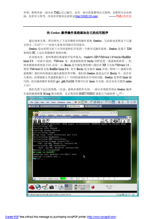
最近闲来无事,所以研究了下这学期所学的操作系统 Geekos。写此贴也是慰念下已逝 去的大二生活^-^……欢迎大家来共同探讨共同进步。
Print("=====================ThreadInformation============= ===============\n");
while(currentthread!=NULL) {
Print("pid:%d",currentthread->pid);
Print("esp:%ld,numticks:%ld,priority:%d,stackPage:0x%x\n",cur rentthread->esp,currentthread->numTicks,currentthread->priori ty,currentthread->stackPage);
Print("owner'pid:%d,alive:%d\n",currentthread->owner->pid,curr entthread->alive); Print("\n"); currentthread=Get_Next_In_All_Thread_List(currentthread); }
联想一键恢复OKR7.0工程版出厂备份

安装联想一键恢复7.0工程版以及制作出厂备份小罗:建议用一键恢复7.0工程师版第一版制作隐藏区先说一下我的本本是Y430,原先使用的是联想一键恢复6.0工程版,由于速度恢复和备份速度慢,所以毅然决定更换联想一键恢复7.0工程版。
首先下载联想一键恢复7.0工程师版ed2k://|c62ee360b9db9875a268e0|h=7s5e7gpnlsy7lal7625rpoyceuoehnew|/(此为第一版有三种安装方式)(此为第二版,只有一种安装方式)(此为第三版分xp vista win7 三种)附上MD5下载之后顺便也把联想windows7OEM旗舰版的系统给下载一下thunder://QUFodHRwOi8vY2FjaGVmaWxlOS5yYXlmaWxlLmNvbS96aC1jbi9kb3 dubG9hZC9mMDA0MGQzZjI2OGIzOWRiMTdkOWIwMDBlNjlmYWEwZC9MRU5PV k9fV0lON19VTV8zMl9aSF9DTl9SRFZELmlzb1pa附上MD5都下载完之后就可以把镜像刻录到光盘或者写入U盘,由于家里没有多余的光盘了,所以我选择写入U盘打开UltraISO-文件-打开-把联想一键恢复7.0添加进去然后点击“启动”,在弹出的菜单中点击“写入硬盘”(windows7系统也是同样的方法)写入完成之后就是重启,然后按F12选在USB启动第三个USB启动。
选择开始读取。
以下介绍的是第二版安装,是要格式化全盘的,如果有重要文件建议先备份或者安装第一版,第一版有3个选择,分别是全新安装(及格式化全盘),修复安装(不影响当前系统以及分区),修复热键。
但要注意的是选择修复安装之前要把最后一个隐藏的主分区删除。
如果以前没有隐藏分区的应该在最后分出10G以上的分区,再删掉读取这里他会跳出这个,意思是硬盘里数据都会丢失。
点击OK。
此时硬盘里面都东西都会被格式化掉,格式化完之后,它会要求你输入C盘的容量,我选择了40961MB=40GB。
inspire 2 用户手册说明书

惠威HR70遥控器使用说明书
HR070 Series Remote Control Programming Guide
6. Repeat steps 1 to 5 for the other components you want to control. For future reference, write down each working component code below:
HR Series Remote Control Programming
Assigned Push-button Component Program Code
TV
CBL
SAT
AUX
DVR
Push-buttons available for Programming
Flashes during Programming
4
Used to activate Programming Mode
with the most popular code first. If the component
responds, go to step 7.
6. If the component does not respond, press LEVEL+
Push-button and the Remote Control will test
The HR70 Series Remote Controls have stored in permanent memory the necessary information to send the correct commands to the component to be controlled. By entering a five digit numeric code the commands for controlling the component is activated.
GeekOS操作系统课程设计project0-4讲解
第二章 设计项目1
一、项目设计目的 熟悉ELF文件格式,了解GeekOS系统如 何将ELF格式的可执行程序装入到内存, 建立内核进程并运行的实现技术。
二、项目设计要求
1、修改/geekos/elf.c文件:在函数 Parse_ELF_Executable( )中添加代码,分析 ELF格式的可执行文件(包括分析得出ELF文件 头、程序头,获取可执行文件长度,代码段、 数据段等信息),并填充Exe_Format数据结 构中的域值。
Stack (4096)
Data Code
3、内核线程的建立流程(建议删除)
Spawn_Init_Process() Start_Kernel_Thread()
Spawner() Read_Fully() Parse_ELF_Excutable() Spawn_Program()
4、创建内核函数过程(新增)
3. 在Linux环境下编译系统得到GeekOS镜像文 件。
4. 编写一个相应的bochs配置文件。
5. 在bochs中运行GeekOS系统显示结果。
四、作业题 1. GeekOS系统内核是如何编译的? 2. GeekOS系统内核编译的结果是什么? 3. 如何设置运行GeekOS系统的计算机环境? 4. 如何运行GeekOS系统内核? 5. GeekOS系统是如何创建键盘管理进程? 6. 简述计算机系统的启动流程。
一、项目设计目的
熟悉GeekOS的项目编译、调试和运行环 境,掌握GeekOS运行工作过程。 二、项目设计要求
1、搭建GeekOS的编译和调试平台,掌 握GeekOS的内核进程工作原理。
2、熟悉键盘操作函数,编程实现一个 内核进程。该进程的功能是:接收键 盘输入的字符并显示到屏幕上,当输 入ctrl+d时,结束进程的运行。
冠捷显示器说明

K120 用户手册说明书

用户手册Rugged Mobile Computing Solutions2022年9月注册商标Bluetooth ® 字标和徽标是归 Bluetooth SIG, Inc. 所有的注册商标。
Thunderbolt是Intel Corporation 或其子公司的商标。
所有品牌名称和产品名称分别是其各自所有者的商标或注册商标。
注意本手册之内容本公司享有随时修改之权利,且不另行通知。
最新版本手册请造访Getac官方网站取得。
目录第1章开始工作 (1)准备开始 (2)开箱检查 (2)安装电池组 (3)安装micro-SIM卡(可选) (4)使用笔绳 (4)连接电源 (5)电脑开机和关机 (7)硬件组件介绍 (8)平板电脑组件 (8)键盘底座组件(可选) (15)多种使用模式 (20)切换使用模式 (21)打开和关闭屏幕上盖 (23)第2章基本操作 (25)在螢幕上操作 (26)使用触摸屏 (26)使用多点触控手势 (27)使用双模式型屏幕(可选) (28)使用键盘底座(可选) (29)使用键盘 (29)使用触摸板 (33)使用网络和无线连接功能 (35)使用LAN网络功能 (35)使用WLAN无线局域网功能 (36)使用蓝牙功能 (37)使用WWAN功能(可选) (38)第3章电力的运用 (39)电源适配器 (40)电池充电 (41)将电池初始化 (41)检视电池电量 (42)电量不足的信号和动作 (42)更换电池组 (43)节能小提示 (45)第4章使用可选模块和外设 (46)使用指纹传感器(可选) (47)建立指纹 (47)指紋登录 (48)使用条形码扫描仪(可选) (49)备注 (50)连接外设 (51)连接显示器 (51)连接USB设备 (52)连接Thunderbolt™ 设备 (52)连接设备进行USB充电 (53)连接串行设备 (54)连接音频设备 (55)使用各种读卡器 (56)使用Smart Card智能卡(可选) (56)使用NFC/RFID阅读器(可选) (57)替换或拆装 (58)替换SSD固态磁盘 (58)第5章BIOS 设置 (59)何时和如何使用 (60)菜单说明 (61)Information菜单 (61)Main菜单 (61)Advanced菜单 (61)Security菜单 (63)Boot菜单 (64)Exit菜单 (64)第6章使用 Getac 软件 (66)OSD 工具 (67)G-Manager (68)第7章产品维护 (70)保护电脑 (71)使用防毒措施 (71)使用安全锁 (71)平时维护 (73)地点准则 (73)一般准则 (73)清理准则 (74)电池准则 (74)触摸屏准则 (75)携带远行时 (76)第8章故障排除 (77)初步检查要项 (78)解决一般性的问题 (79)电池问题 (79)蓝牙无线传输问题 (79)显示问题 (80)指纹传感器问题 (80)硬件设备问题 (81)键盘和触摸板问题 (81)LAN网络问题 (82)电源管理问题 (82)软件问题 (83)音频问题 (83)开机问题 (83)WLAN无线局域网问题 (84)其他问题 (85)重新开机 (86)系统恢复 (87)使用Windows恢复环境(Windows RE) (87)使用恢复分区 (Recovery Partition) (88)使用驱动程序光盘(可选) (89)附录A规格 (90)平板电脑规格 (91)键盘底座规格 (93)附录B管制信息 (94)安全注意事项 (95)关于电池 (95)关于电源适配器 (96)关于发烫和温度 (97)美國ANSI警語 (97)关于K120-Ex (99)安全使用的特别条件 (99)防爆保护盖 (99)配件的使用 (100)产品中有害物质的名称及含量 (101)ENERGY STAR能源之星 (102)第 1 章章开始工作本章首先教导您如何将电脑准备好,以便让您开始工作。
编译Linux内核
编译Linux内核实验目的学习重新编译Linux内核,理解、掌握Linux内核和发行版本的区别。
实验内容重新编译内核是一件比你想像的还要简单的事情,它甚至不需要你对内核有任何的了解,只要你具备一些基本的Linux操作系统的知识就可以进行。
本次实验,要求你在RedHat Fedora Core 5的Linux系统里,下载并重新编译其内核源代码(版本号KERNEL-2.6.15-1.2054);然后,配置GNU的启动引导工具grub,成功运行你刚刚编译成功的Linux内核。
实验提示Linux是当今流行的操作系统之一。
由于其源码的开放性,现代操作系统设计的思想和技术能够不断运用于它的新版本中。
因此,读懂并修改Linux内核源代码无疑是学习操作系统设计技术的有效方法。
本实验首先介绍Linux内核的特点、源码结构和重新编译内核的方法,讲述如何通过Linux系统所提供的/proc虚拟文件系统了解操作系统运行状况的方法。
最后,对Linux编程环境中的常用工具也有简单介绍。
1.1查找并且下载一份内核源代码我们知道,Linux受GNU通用公共许可证(GPL)保护,其内核源代码是完全开放的。
现在很多Linux的网站都提供内核代码的下载。
推荐你使用Linux的官方网站: ,如图1-1。
在这里你可以找到所有的内核版本。
图1-1 Linux的官方网站由于作者安装的Fedora Core 5并不附带内核源代码,第一步首先想办法获取合适版本的Linux内核代码。
通过命令# uname –r2.6.15-1.2054_FC5这就是说,RedHat Fedora Core 5采用的内核版本是2.6.15-1.2054_FC5。
但是,官方网站/pub/linux/kernel/找不到对应版本。
请别着急,既然它是RedHat发布的,RedHat的官方网站总有吧。
浏览/pub/fedora/linux/core/5/source/SRPMS,我们发现果然有文件kernel-2.6.15-1.2054_FC5.src.rpm,这个rpm文件就是2.6.15-1.2054_FC5版的内核源代码了。
联想一键恢复6.0工程师版软件安装教程
联想一键恢复6.0工程师版软件教程(1)安装前准备工作a. 客户硬盘数据备份:除非是刚更换的空白硬盘,否则备份硬盘数据在任何时候都是非常有必要的。
针对磁盘分区的任何操作,都有可能导致硬盘数据丢失的可能!b. 安装软件准备:下载知识文档附件“OneKey6.0_for_NB(V1.0)”镜像文件,并通过 Nero 等光盘刻录软件将其刻录到空白的 CD 光盘上面。
刻录后的光盘,包含 DOS 系统启动功能(支持 SATA 光驱)和各个“一键恢复 6.0”软件安装模块。
c. 待安装机器准备:准备好待安装“一键恢复6.0”的机器及外接适配器电源。
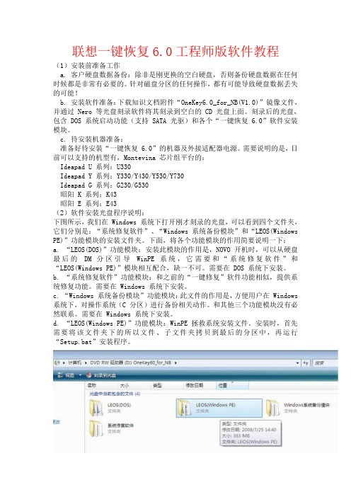
需要说明的是,目前可以支持的机型有,Montevina 芯片组平台的:Ideapad U 系列:U330Ideapad Y 系列:Y330/Y430/Y530/Y730Ideapad G 系列:G230/G530昭阳 K 系列:K43昭阳 E 系列:E43(2)软件安装光盘程序说明:下图所示,我们在 Windows 系统下打开刚才刻录的光盘,可以看到四个文件夹,它们分别是:“系统修复软件”、“Windows 系统备份模块”和“LEOS(Windows PE)”功能模块的安装文件夹。
下面,将各个功能模块的作用简要说明一下:a. “LEOS(DOS)”功能模块:安装此模块的作用是,NOVO 开机时,可以从硬盘最后的DM 分区引导WinPE 系统,它需要和“系统修复软件”和“LEOS(Windows PE)”模块相互配合,缺一不可。
需要在 DOS 系统下安装。
b. “系统修复软件”功能模块:和之前的“一键修复”软件功能相似,提供系统修复功能。
需要在 Windows 系统下安装。
c. “Windows 系统备份模块”功能模块:此文件的作用是,方便用户在 Windows 系统下,对操作系统(C 分区)进行备份相关动作。
和其他三个功能模块没有必然联系。
需要在 Windows 系统下安装。
安捷伦系列芯片简介(鼠标专用ic)

安捷伦系列芯片简介安捷伦和安华高安捷伦科技(NYSE:A)是由美国惠普公司战略重组分立而成的,其业务重点包括通信、电子及化学分析与生命科学。
1999 年11月18日, 安捷伦科技以代码“A”在纽约股票交易所挂牌上市。
虽然在除了光学传感之外的领域里,安捷伦也取得了巨大的成就。
但是对于广大玩家来说,大家提起安捷伦(AGILENT),还是首先想起它作为世界上最著名的鼠标用光学/激光感应器材的生产厂家。
的确,在上世纪90年代和本世纪初的这段时间里,安捷伦几乎是高档光电/激光鼠标芯片的代名词,作为安捷伦历史悠久的合作伙伴,在上世纪末,在MS和安捷伦勾搭上之前,LOGITECH几乎是垄断了高端外设的市场。
而在山的那一边,那条叫RAZER的小蛇,当时连牙还没有长全呢~在2005年8月,投资公司Kohlberg Kravis Roberts & Co.会同风险投资商Silver Lake Partners,以26.6亿美的价格并购了安捷伦科技。
并购后,新成立了公司A V AGO,也就是现在大家所说的安华高,并且号称全球最大的非上市独立半导体公司。
Avago Technologies 拥有5,500多种系列产品,主要应用于无线和有线通信、工业、汽车、消费电子及存储和计算机等广阔的应用领域和终端市场。
它在光电耦合器、红外线收发器、光通信器件、打印机ASIC、光学鼠标传感器和运动控制编码器等领域一直保持市场前3名的领导地位。
通过并购,安华高遗传了安捷伦全部的研发能力和市场网络,并且将其在光电鼠标处理芯片上的技术优势地位继续延续。
在下面的文章中,在介绍产品的时候,我决定仍然使用安捷伦这个名字,也当作是对它的一个怀念和敬意吧首先补充一点小知识,有关激光引擎和光学引擎的激光引擎和光学引擎的区别~~~从原理上来讲是类似的,但是由于激光是相干光~ 所以具有比LED光源更好的特性~ 安捷伦自己的描述是这样的A, LED光学引擎的原理示意图B,激光引擎的原理示意图C, 激光比LED引擎的优越性D, 激光可支持更多的表面激光引擎可以支持的表面包括:纸,木材,包装纸,粗斜纹棉布,棉布,榻榻米(!),地毯(!),金属,瓷砖,塑料,福米卡塑料(!?),网格(!!!)LED引擎可以支持的表面包括:纸,木材,包装纸,粗斜纹棉布,棉布,纯黑表面安捷伦到目前为止,所出产的鼠标应用方案如下:LED光学引擎系列型号系列描述ADNS-2030 无线系列低功率光学传感器,为无线应用优化ADNS-2051 有线系列中频光学传感器,为有线/无线应用ADNS-2610 有线(小型封装)入门级,小型封装光学传感器,为普通鼠标应用ADNS-2620 有线(小型封装)入门级,小型封装光学传感器,性能提高ADNS-3040 无线系列超低功率光学传感器,为无线应用优化ADNS-3060 有线系列高性能光学传感器ADNS-3080 游戏系列高分辨率光学传感器,为游戏应用ADNS-3530 MINI系列 MINI系列低功率,芯片-基板-LED整合设计光学传感器,为无线应用设计ADNS-3550 MINI系列 MINI系列低功率,芯片-基板-LED整合设计光学传感器,为无线应用设计ADNS-5000 有线系列基于LED的导航传感器ADNS-5020-EN 有线(小型封装)小型封装光学传感器,较入门级性能有所提高ADNS-5030 无线(小型封装)低功率,小型封装光学传感器,为无线应用设计ADNS-5050 有线系列性能提升的基于LED的导航传感器LaserStream 激光引擎系列型号系列描述ADNS-6000 有线系列高性能激光鼠标传感器ADNS-6010 游戏系列高分辨率激光鼠标传感器,为游戏设计ADNS-6090 专业游戏系列增强型游戏级激光传感器ADNS-6530 MINI系列 MINI系列低功率,芯片-基板-LED一体化设计激光传感器,为无线应用设计ADNS-7010 休闲游戏系列休闲型游戏级激光传感器ADNS-7050 无线系列低功率激光传感器ADNS-7530 无线系列整合型,入门级,小型封装激光传感器ADNS-7550 有线系列整合型,入门级,小型封装激光传感器目前,以LOGI为主的厂家,包括MS等,以及国产的双飞燕等,均广泛使用安捷伦的芯片进行一下总结:作为业界的领袖企业,安捷伦(安华高)的芯片发展,也代表这整个业界的技术发展方向。
aegisub字幕轴代码格式说明书
00 代码格式说明反斜线符号\+代码名称+参数(有可能为多个)*所有代码必须是英文格式,中文标点无效(生效了的代码是彩色的);*尖括号< >内的参数必填;*<>本身不需要输入代码;*[ ] 内参数可以省略,具体用法参照相关内容。
e.g.\fs<size> \fs50 【字体大小设置为50】\pos (<x>, <y>) \pos(470, 260) 【字幕位置定位于点(<x>, <y>)】\move (<x1>, <y1>, <x2>, <y2> [, <t1>, <t2>])\move (100, 150, 300, 350)【字幕从点(100, 150) 移动至(300, 350),持续时间为从字幕出现开始到字幕消失为止】✲゚*.✲ *.✲゚*. ✲゚✲゚*.✲゚*. ✲゚✲゚* *.✲゚*. ✲゚✲゚*. *.✲゚*. ✲゚*.✲゚*. ✲゚*.✲゚* *.✲゚*. ✲゚*.✲゚*.01特殊代码Special characters (不需写在{ } 内)\n –软性换行Soft line break【只在换行方式(Wrapping mode) 2(详情见下↓) 下有效,其他方式下则被替换为空格】\N –硬性换行Hard line break【无视换行方式,强制换行】\h –硬性空格Hard space【在硬性空格前后不会自动换行,且其在一行首尾时不会被缩进】换行方式Wrap Style:\q<style> (Override tag)*此为Override tag,需要{},写在这里仅为方便对照查阅;*共计四种,可在“文件→配置”中更改。
0:智能换行,尽量使每行宽度一致,不能保持等宽时上行较宽。
只有\N指令强制换行有效;1:于行尾词处换行,仅\N断行有效;2:不自动换行,\n及\N断行有效;3:智能换行,尽量使每行宽度一致,不能保持等宽时下行较宽。
摩克斯 V2201 系列超级紧凑型 x86 嵌入式计算机安装指南说明书

P/N: 1802022010014 *1802022010014*V2201 SeriesQuick Installation GuideVersion 3.2, April 2022Technical Support Contact Information/support2022 Moxa Inc. All rights reserved.OverviewThe Moxa V2201 Series ultra-compact x86 embedded computer is based on the Intel® Atom™ E3800 Series processor, features the most reliable I/O design to maximize connectivity, and supports dual wireless modules, making it suitable for a diverse range of communication applications. The computer’s thermal design ensures reliable system operation in temperatures ranging from -40 to 85°C, and wireless operation in temperatures ranging from -40 to 70°C with a special purpose Moxa wireless module installed. The V2201 Series supports Proactive Monitoring function for device I/O status monitoring and alerts, system temperature monitoring and alerts, and system power management. Closely monitoring the system status makes it easier to recover from errors and provides the most reliable platform for your applications.Package ChecklistBefore installing the V2201, verify that the package contains the following items:•V2201 embedded computer•Terminal block to power jack converter•Wall mounting kit•Quick installation guide (printed)•Warranty cardNOTE: Please notify your sales representative if any of the above items are missing or damaged.V2201 Panel LayoutThe following figures show the panel layouts of the V2201-W models; for “non-W” models, the five antenna connectors will not be installed during production.Front PanelRight PanelLeft PanelLED IndicatorsThe following table describes the LED indicators located on the front panel of the V2201.LED Name Status Function Power Green Power is on and computer is functioning normally.Off Power is offUser Defined Red Event has occurred Off No alert mSATA Yellow Blinking: Data is being transmittedOff Not connected / No data transmissionSD Card Yellow Blinking: Data is being transmittedOff Not connected / No data transmissionWireless 1 Green Steady On: Link is OnBlinking: Data is being transmittedOff Not connectedWireless 2 Green Steady On: Link is OnBlinking: Data is being transmittedOff Not connectedLED Name Status Function LAN 1Yellow Steady On: 1000 Mbps Ethernet linkBlinking: Data is being transmittedGreen Steady On: 100 Mbps Ethernet linkBlinking: Data is being transmittedOff 10 Mbps Ethernet link or LAN is not connectedLAN 2 Yellow Steady On: 1000 Mbps Ethernet linkBlinking: Data is being transmittedGreen Steady On: 100 Mbps Ethernet linkBlinking: Data is being transmittedOff 10 Mbps Ethernet link or LAN is not connectedTx 1 Green Blinking: Data is being transmittedOff Not connectedTx 2 Green Blinking: Data is being transmittedOff Not connectedRx 1 Yellow Blinking: Data is being transmittedOff Not connectedRx 2 Yellow Blinking: Data is being transmittedOff Not connectedInstalling the Wireless ModulesThe V2201 has two Mini PCIe sockets on the rear panel. One socket only supports USB signals using the MC9090, MC7354, or MC7354 Mini PCIe cards. The other socket supports standard USB and PCIe signals.STEP1: Loosen the four screws located at the middle of the rear panel and open the cover.STEP 2: Insert the wireless module card at an angle.STEP 3: Push the wireless module card down and fasten it with the two screws included with the product.The V2201 has the following two Mini PCIe sockets.Socket 1: USB signal, for 3G/LTE Mini PCIe card (Sierra Wireless MC9090, MC7304, or MC7354). NOTE: The cellular card heat sink is installed in socket 1. Socket 2: Standard USB + PCIe signals, for Wi-Fi Mini PCIe card (SparkLAN WPEA-252NI).STEP 4: Connect the corresponding wireless module cards to connectors of the Mini PCIe sockets.The following five connectors are available:No. 1 & No. 3:For the Wi-Fi Mini PCIe card No. 2 & No. 4:For the 3G/LTE Mini PCIe card No. 5:For the GPS moduleSTEP 5: Replace the rear cover.You can also purchase and install external 3G, 4G, and Wi-Fi antennas from Moxa. Contact a Moxa sales representative for information. After installing the wireless modules and wireless external antennas, the computer should appear as follows:Installing the V2201DIN-rail MountingThe DK-DC50131 die-cast metal kit (shipped only with V2201-E4-W-T-LX; purchase separately for all other models), enables easy and robust installation of the V2201. Use the six M4*6L FMS screws included toattach the DIN-rail mounting kit to the side panel of the V2201.Installation:STEP 1:Insert the upper lip of the DIN rail intothe DIN-rail mounting kit.STEP 2:Press the V2201 towards the DIN railuntil it snaps into place.Removal:STEP 1:Pull down the latch on themounting kit with a screwdriver.STEP 2 & 3:Use the screwdriver to pry theV2201 slightly forward away fromthe DIN rail, and then lift theV2201 upwards to remove it fromthe DIN rail.STEP 4:Press the recessed button on the spring-loaded bracket to lock it into position untilthe next time you need to install theV2201 on to a DIN rail.Wall or Cabinet MountingThe V2201 computers (with the exclusion of the V2201-E4-W-T-LX model) come with two metal brackets for attaching to a wall or the inside of a cabinet. Four screws (Phillips truss-headed M3*6L nickel plated with Nylok®) are included in the kit.Step 1:Use two screws for eachbracket and attach the bracketto the rear of the V2201.Step 2:Use two screws on each side toattach the V2201 to a wall orcabinet.The product package does notinclude the four screws requiredfor attaching the wall-mountingkit to the wall or cabinet; theyneed to be purchasedseparately. We recommendusing standard M3*5L screws.Connector DescriptionPower ConnectorConnect the 9 to 36 VDC LPS or Class 2 power line to the V2201’s terminal block. If the power is supplied properly, the Power LED will light up. The OS is ready when the Ready LED glows a solid green.Grounding the V2201Grounding and wire routing help limit the effects of noise due to electromagnetic interference (EMI). Run the ground connection from the grounding screw (M4) to the grounding surface prior to connecting the power.SG:The Shielded Ground (sometimes calledProtected Ground) contact is the right most oneon the 3-pin power terminal block connector when viewed from the angle shown here.Connect the SG wire to an appropriate grounded metal surface.HDMI OutputsThe V2201 comes with a type A HDMI female connector on the front panel to connect an HDMI monitor.The screw hole above the HDMI connector is used to attach a custom lock to the HDMI connector; a custom lock is needed since the shape of different HDMI connectors are not the same. Please contact a Moxa sales representative for details. Before Attaching the LockAfter Attaching the LockEthernet PortsThe 10/100/1000 Mbps Ethernet ports use RJ45 connectors.Pin 10/100 Mbps 1000 Mbps1 ETx+ TRD(0)+2 ETx- TRD(0)-3 ERx+ TRD(1)+4 – TRD(2)+5 – TRD(2)-6 ERx- TRD(1)-7 – TRD(3)+8 – TRD(3)-Serial PortsThe serial ports use DB9 connectors. Each port can be configured by software for RS-232, RS-422, or RS-485. The pin assignments for the ports are shown in the following table:Pin RS-232 RS-422 RS-485(4-wire) RS-485(2-wire)1 DCD TxDA(-) TxDA(-) –2 RxD TxDB(+) TxDB(+) –3 TxD RxDB(+) RxDB(+) DataB(+)4 DTR RxDA(-) RxDA(-) DataA(-)5 GND GND GND GND6 DSR – – –7 RTS – – –8 CTS – – –SD SlotThe V2201 has an SD slot for storage expansion. The SD slot allows users to plug in an SD 3.0 standard SD card. To install an SD card, gently remove the outer cover from the left, and then insert the SD card into the slot.USIM SlotThe V2201 has a USIM slot for 3G/LTE wireless Internet connections. To install a USIM card, gently remove the outer cover from the left, and then insert the USIM card into the slot.USB HostsThe V2201 has 1 USB 3.0 and 2 USB 2.0 Type-A connectors. 2 USB 2.0 ports are located on the front panel, and 1 USB 3.0 port is on the right panel. The port supports keyboard and mouse and can also be used to connect a Flash drive for storing additional data.Audio InterfaceThe audio output of the V2201 is combined with the HDMI connector.DI/DOThe V2201 comes with four digital inputs and four digital outputs on a 2 x 5 terminal block.Reset ButtonPress the “Reset Button” on the left side panel of the V2201 to reboot the system automatically. Real-time ClockThe V2201’s real-time clock is powered by a lithium battery. Westrongly recommend that you do not replace the lithium battery without help from a qualified Moxa support engineer. If you need to change the battery, contact the Moxa RMA service team.Powering on the V2201To power on the V2201, connect the “terminal block to power jack converter” to the V2201’s DC terminal block (located on the sidepanel), and then connect the 9 to 36 VDC power adapter. The computer is automatically switched on once the power adapter is plugged in. If it does not, press the Power Button to turn on the computer. Note that the Shielded Ground wire should be connected to the top pin of the terminal block. It takes about 30 seconds for the system to boot up. Once the system is ready, the Power LED will light up.Connecting the V2201 to a PCPower on the V2201 computer after connecting a monitor, keyboard, and mouse, and verifying that the power source is ready. Once the operating system boots up, the first step is to configure the Ethernet interface. The factory default settings for the V2201’s LANs are show below (W7E uses DHCP).Default IP AddressNetmaskLAN 1 192.168.3.127 255.255.255.0 LAN 2 192.168.4.127255.255.255.0- 11 - Configuring the Ethernet Interface Linux OSIf you use the console cable to configure network settings for the first time, use the following commands to edit the interfaces file:#ifdown –a //Disable LAN1~LAN2 interface first, before you reconfigure the LAN settings. LAN1 = eth0, LAN2 = eth1// #vi /etc/network/interfaces //check the LAN interface first//After the boot setting of the LAN interface has been modified, use the following commands to immediately activate the LAN settings: #sync; ifup –a W7E OSSTEP 1: Go to Start → Control Panel → Network and Internet → Viewnetwork status and tasks → Change adapter setting.STEP 2: In the Local Area Connection Properties screen, click InternetProtocol (TCP/IP) and then select Properties. Select InternetProtocol Version 4, and then click Properties.STEP 3: Click OK after inputting the proper IP address and netmask.。
终结者卡片电脑(NanoPC-T1)Ubuntu 内核编译指南说明书
NanoPC-T1 Ubuntu内核编译指南V1.0 (2014-05-23)更新说明:日期改动2014-05-23 首次发布目录1.安装交叉编译工具......................................................................................................................................................- 4 -2.编译内核......................................................................................................................................................................- 6 -3.内核驱动所在位置......................................................................................................................................................- 9 -1.安装交叉编译工具1.1 下载交叉编译工具下载地址:/nanopc-t1.asp下载完成后得到压缩包:arm-linux-gnueabihf-4.7.tar.gz1.2 安装交叉编译工具(1)解压:# sudo tar xzf arm-linux-gnueabihf-4.7.tar.gz -C /opt(2)添加环境变量:在/etc/profile文件的最末尾添加下面这句话:export PATH=/opt/arm-linux-gnueabihf-4.7/bin/:$PATH (3)重启电脑,输入如下命令检查工具链是否按照成功:# arm-linux-gnueabihf-gcc -v出现如下信息则说明安装成功:2.编译内核2.1 下载内核源码下载地址:/nanopc-t1.asp下载完成后后会得到压缩包:linux-3.8.13-nanopc-t1-140523.tar.gz 140523表示发布日期,我们会不定期更新,请以实际情况为准。
鹅力 Evolis Premium Suite 打印机说明书

STANDARD PRINTER FEATURES SOFTWARE CARD SPECIFICATIONS Printer design:Delivered with Evolis Premium Suite ® for Windows ®:• 100-card input hopper capacity (0,76mm - 30mil)• Compact printer for desktop environment • Printer driver • 100-card output hopper capacity (0,76mm - 30mil)• Available in fire red or brilliant blue• Evolis Print Center for administration and settings • 30-card reject tray capacity (0,76mm - 30mil)• LED control panel• Evolis Printer Manager for graphical notifications 3• Card thickness: 0,25 to 1,25mm (10 to 50mil)Print technology:• 24/7 online support Gauge adjustment • Direct-to-card• Compatible with Windows ® XP SP3 32/64,0,25mm (10mil) only for monochrome printing • Dye-sublimation/resin thermal transferVista 32/64, W7 32/64, W8 32/64, W10• Input hopper low card level and empty detection Print capability:• User interface languages available: English, French,Card types accepted:• One-or two-sided printing, edge-to-edgeSpanish, German, Italian, Portuguese (Brazil), • ISO 7810 format, Type ID 1, CR-80 size Print resolution:Dutch, Simplified Chinese, Traditional Chinese,• 85,6 x 53,98 mm (3.370" x 2.125")• 16 million colorsJapanese, Korean, Russian, Polish, Turkish, Farsi • PVC, Composite PVC, PET • Standard mode: 300x300 dpi (dots per inch)Delivered with cardPresso XXS for designing and • ABS 1, special varnished cards 1 For standard monochrome and color printingediting badges:• Extended mode: 300x600 dpi (dots per inch)• Internal database (unlimited records)PRINTER SPECIFICATIONS For e nhanced monochrome and color printing• Signature acquisition (compatible with Evolis Sig100Physical dimensions (H x W x D):• Extended mode: 300x1200 dpi (dots per inch)and Sig200 signature pads)• 247 x 205 x 381 mm (9.72" x 8.07" x 14.99") For enhanced monochrome printing• Compatible with Windows ® XP SP3 32/64, Vista 32/64, • With reject tray: 247 x 205 x 481 mm (9.72" x 8.07" x 18.93")Printing performance:W7 32/64, W8 32/64 and Mac OS X (Intel® processor)Weight:• Color YMCKO: up to 225 cards/hour 1Delivered with a driver for Mac OS X (from 10.5 onwards)• 4,02 kg (8.86 lbs)• Color YMCKO-K: up to 140 cards/hourLinux OS, upon request Electronic requirements:• Monochrome: up to 850 cards/hourEvolis Premium SDK for remote supervision of the printer, • Power supply: 100-240 Volts AC, 50-60 Hz, 1.7 A Printer memory:while facilitating and speeding up integration into IT • Printer: 24 Volts DC, 2.71 A • 32 MB (RAM) standard, optional 64 MB 1systems Interfaces:OPERATING ENVIRONMENT • USB (1.0, 1.1, 2.0, 3.0)PRINTER RIBBON SPECIFICATIONS • Min / Max operating temperature: 15° / 30° C (59° / 86° F)• Ethernet TCP-IP, 10BaseT, 100BAseT (Traffic Led)The Primacy is designed to work only with Evolis • Humidity: 20% to 65% non-condensing Safety:High Trust ® ribbons • Min / Max storage temparature: -5° / +70° C (23° / 158° F)• Support for Kensington ® security lockTo maximize the quality and durability of printed • Storage humidity: 20% to 70% non-condensing • Data encryption for magnetic encodingcards, the lifespan of the print head and the overall • Operating ventilation: free air User-friendly operation:printer reliability, use Evolis High Trust ® ribbons • Full front operation• Automatic ribbon identification and setting SOUND (evaluated according to the ISO 7779 • Graphical notifications from the printer 2: cleaning • Delivered in a drop-in cassette for intuitive Sound pressure in assistant positions LpAm (color mode alerts, empty/low level ribbon and card alerts, etc.installation and easy handling YMCKO):• Easy to reach on/off button• Ribbon saver for monochrome printing • When operating: 48 dB (A)• Easy to access technical parts thanks to sideopening • Recyclable supply cores and cassette • In sleep mode: background noise level • Checking of the card level at a glance• Recycled packaging • Drop-in cassette with easy handlingRibbon capacity:CERTIFICATIONS / COMPLIANCES • Operator replaceable print head• YMCKO: 300 prints/roll • Standby, sleep modes & reduced energy consumption Warranty:• YMCKO-K: 200 prints/roll (dual-sided)• Recyclable enclosure plastics • 3-year warranty on printer 4• 1/2 YMCKO: 400 prints/roll • CE, FCC, IEC, VCCI, CCC, KC, BIS, EAC • 3-year warranty on original print head (unlimited• 1/2 YMCKO-KO: 250 prints/roll (dual-sided)• RoHS passes)4• KO: 600 prints/roll • Recyclable packaging • SO-KO: 250 prints/roll (dual-sided)OPTIONAL PRINTER FEATURES• Black monochrome ribbon: 2000 prints/roll INCLUDED WITH THE PRINTER • On-site dual-sided printing activation by a RFID key • BlackFLEXmonochrome ribbon: 1000 prints/roll • CD with drivers and user's manuals • 64 MB (RAM), under specific conditions• Blue P300C monochrome ribbon: 1000 prints/roll • DVD with cardPresso XXS card designer software • USB encoding over IP through additional USB Net • Red P186C monochrome ribbon: 1000 prints/roll • Quick Start Guide Server module, upon request• Green P356C monochrome ribbon: 1000 prints/roll • Warranty booklet • Open output hopper for collecting cards one by one • White monochrome ribbon: 1000 prints/roll • Starter cleaning kit • Wireless range: wireless connection 802.11 b/g• Metallic silver monochrome ribbon: 1000 prints/roll • USB cable (1.80m)• Locking system to prevent acces to the printer• Metallic gold monochrome ribbon: 1000 prints/roll • Reject tray and consumables (cards and ribbons)• Signature panel monochrome ribbon: 1000 prints/roll • Power supply • Warranty extension program• Scratch-off monochrome ribbon: 1000 prints/roll • Power cord (region specific)• Hologram varnish ribbon: 400 prints/roll ENCODING OPTIONS• Magnetic stripe encoder ISO 7811, track 1, 2 and 3Y=Yellow, M=Magenta, C=Cyan, K=Black Resin high and low coercivity, stripe down (0,76mm - 30mil O=Overlay, S=Silver cards only)• Magnetic stripe encoder JIS Type II• ISO 7813 smart card contact station for 3rd partyexternal contact encoder• Contact smart encoder - PC/SC, EMV 2000-1• Contactless ISO 14443A, B, ISO 15693, MIFARE,DESfire, HID iCLASS, UHF encoder: ETSI (EN302208)or FCC (part 15.247) standard compliance:EPC C1 Gen2 / ISO18000-6C• Other specific encoders upon request• Internal USB or IP ports• Options can be combined• Factory-installed or installed on-site CARD PRINTER SPECIFICATIONS ©2015 Evolis. All rights reserved. All information, specifications or graphics are subject to change without prior notice. All trademarks mentioned herein belong to their respective owners. 08/2015. KB-PRM1-126-ENG-A4 Rev A0 Under specific conditions / Depends on the Windows® version / Requires 4.0 client profile version Warranty subject to observance of specific conditions and use of Evolis High Trust® ribbons。
全志A20-Vortex-C2核心板-WIFI-BT移植说明手册V1.1

bt 基本都采用 UART 接口通信。
本文档会不断的更新,文档和代码对应可能会稍有差别。
A20_Android4.2 wifi+bt 配置说明
4
Copyright © 2013 Ococci Technology. All Rights Reserved.
2.2 BoardConfig.mk.......................................................................................................................... 5
2.3 init.sun7i.rc.................................................................................................................................. 6
BOARD_HOSTAPD_DRIVER
:= NL80211
2 rtl8188eu/rtl8188etv................................................................................................................................ 5
3.9 ap6210 模组移植相关文件.......................................................................................................15
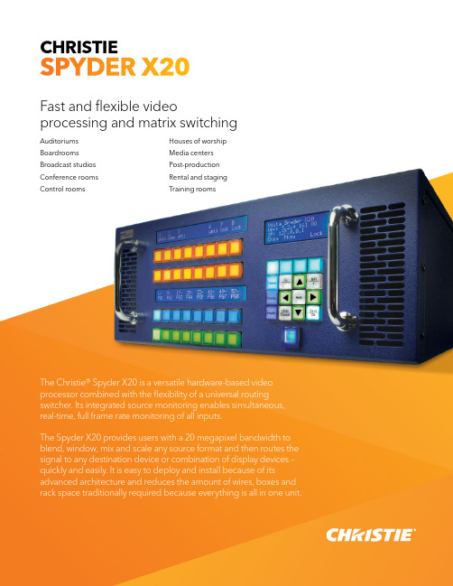
科视Christie Spyder X20 视频处理器指南说明书
CHRISTIE SPYDER X20Fast and flexible video processing and matrix switchingAuditoriums Boardrooms Broadcast studios Conference rooms Control rooms Houses of worship Media centers Post-production Rental and staging Training roomsThe Christie® Spyder X20 is a versatile hardware-based video processor combined with the flexibility of a universal routing switcher. Its integrated source monitoring enables simultaneous, real-time, full frame rate monitoring of all inputs.The Spyder X20 provides users with a 20 megapixel bandwidth to blend, window, mix and scale any source format and then routes the signal to any destination device or combination of display devices – quickly and easily. It is easy to deploy and install because of its advanced architecture and reduces the amount of wires, boxes and rack space traditionally required because everything is all in one unit.Unrestricted multi-window processingThe Christie® Spyder X20 offers a unique architecture that allows for a resolution and video-format-independent environment. Users are no longer restricted to the resolution of a single computer or video source, or a single display destination. Multiple displays can be combined to generate an enhanced resolution to exceed what any single display can support.Ideal for live event and broadcast environments, its20 megapixel bandwidth enables the Spyder X20 to drive multiple displays to achieve higher brightness, image quality and resolution. The Spyder X20 can be used in many different environments and with any combination of display devices.Key featuresAdditional features › 20 megapixel bandwidth › I nternal matrix switching›Universal input/output capabilities – mix and matchmultiple formats with one piece of equipment›Input capability – either 8 or 16 inputs (depending onmodel) that can be a mix of analog BNC and DVI signals›Output capability – 8 outputs that natively support anydisplay from component analog 480i to digital 4K›Built-in conversion for analog/digital, interlaced/progressive, resolution, aspect ratio and refresh rate›2D and 3D capabilities›Manages and displays multiple 3D sources›Define properties for each output independentof each signal›Integrated source monitoring – real-time and fullframe-rate view of all sources connected to the Spyder X20 (either 16 or 8 inputs) on a single output, tiled into either a 4x4 array (X20-1608) or a 4x2 array (X20-0808)›Single point of control for all processing and signaldistribution functions from front panel, PC via Ethernet, or external control system›10-bit processing›Small form factor – (LxWxH): 21.9 x 17.3 x 7.0" (556 x 439x 178mm). Additionally, only one piece of equipment is required so the overall space used in a rack is reduced›Each output individually supports rotation –enabling the creation of vertically-oriented displays›User-definable edge blending and tiling›Create any kind of window border or drop shadowwith adjustable color, width, softness, shadow offset and transparency›Online editing mode allows for preset displays to be builtand edited in preview mode without affecting what the audience is seeing›Built-in image Still Storefunctionality›Built-in VESA calculatorfor custom resolution outputs›Intuitive graphical userinterface (GUI)›Simple cohesive controlof all functions›Redundant hot swappablepower supplies›Optional stereoscopicsupport›Advanced auto-syncfunctionality›Bitmap borders ›Window titling›Optional HDCP supportThis generation of SpyderThe Spyder X20 is designed for users in any environment to take images from unique sources, use a variety of display systems and present the images as intended. It is ideal for applications such as live events, broadcast, high-end boardrooms, command and control, houses of worship and education – anyinstallation that has multi-windowing, multiple displays and processing requirements.The Spyder X20 also offers the flexibility to display 2D and 3Dcontent simultaneously in the same display.Remote PC functionality allows the support of multiple remote servers to match certain securityrequirements and classification levels Software interfaceThe Microsoft® Windows® based control software provides full set-up, configuration, and real-time controlwith an easy-to-use interface.V ista Advanced is a Windows-based software interface that makes it easy to configure and control the Spyder X20.R educed rack spaceB itmap bordersFor the most current specification information, please visit Copyright 2022 Christie Digital Systems USA, Inc. All rights reserved. All brand names and productnames are trademarks, registered trademarks or tradenames of their respective holders. Performance specifications are typical. Due to constant research, specifications are subject to change without notice. CHRI4546_SpyderX20_Brochure_DEC_21_EN。
GeekOS实验注意事项
GeekOS实验注意事项一、Linux下GeekOS实验所需要的软件主要有nasm和bochs (音box)。
1、nasm推荐使用0.98这个版本。
如果用比较新的版本nasm编译生成的系统镜像会出错。
直接下载linux下的可执行文件,拷贝到/usr/bin/这个目录下,然后在终端中输入:sudo chmod +x /usr/bin/nasm2、bochs目前官网上最新的版本是2.6。
下载bochs-2.6.tar.gz 这个文件,并拷贝到主目录下(一般都是/home/XXX)。
用在终端中输入tar xzvf bochs-2.6.tar.gz 解压缩这个压缩包。
然后cd bochs-2.6,在bochs-2.6这个目录下执行 ./configure 然后执行make 最后执行sudo make install这样就把bochs安装到/usr/local/bin这个目录下了。
./configure后面还可以接参数--prefix=/opt --enable-debugger,这两个参数的意思分别是指定安装目录/opt、打开调试功能,这个调试功能是汇编级别的,还有一个用gdb调试c语言级别的内核代码,需要把--enable-debugger这个参数换成--enable-gdb-stub,调试功能打开后每次启动系统都会要求输入调试的命令比较麻烦,可以分别编译三次,一次打开汇编级别调试功能,一次打开c 语言级别调试功能,一次不打开调试功能。
然后把打开汇编级别调试功能编译的可执行文件重命名为bochsdbg 看,打开c语言级别调试功能的可执行文件重命名为bochsgdb,然后拷贝到/usr/local/bin下面。
3、bochs安装好了之后要修改bochs的配置文件,对于GeekOS 来说,每一个project下面的build目录下都有一个.bochsrc文件。
对于project0使用这个配置文件即可:gdbstub: enabled=1, port=1234, text_base=0, data_base=0, bss_base=0 romimage:file=$BXSHARE/BIOS-bochs-latest megs: 8boot: afloppya:1_44=fd.img, status=insertedlog: ./bochs.out对于project1使用这个配置文件即可:romimage:file=$BXSHARE/BIOS-bochs-latestmegs: 8boot: afloppya: 1_44=fd.img, status=insertedata0-master:type=disk, mode=flat, path="diskc.img", cylinders=0log: ./bochs.out二、编译GeekOS:打开终端,依次输入下面三条命令。
GeekOS入门 2010

GeekOS-0.3.0入门一、编译project执行如下命令序列:$ cd /home/sf/work/project0/build$ make depend$ make clean$ make系统在build/目录下生成了文件fd.img.二、运行$ cd /home/sf/work/project0/build$bochs执行bochs之后,显示的第一个画面:选择5开始执行。
选择5后,执行的画面如下:其中,背景画面是一个黑屏,相当于启动电脑后但还没有执行BIOS的一瞬间的情景。
前景画面是bochs的调试画面,在光标提示下可以输入各种调试命令。
调度命令如下:运行结果可能会出现如下:恭喜!这说明已经把project0成功安装到你的机器上了。
如果现在就想体会修改OS内核的喜悦,可以按如下操作进行:可以使用gedit打开/home/sf/work/project0/src/main.c修改main.c文件:把第51行Printf(“Hello project0!”)保存并退出重新编译新内核并运行:执行如下命令序列:$ cd /home/sf/work/project0/build$ make depend$ make clean$ make$ bochs看到“Hello project0!”了吧,OK!当然,这只是小修改,如果按照project0的要求,还需要把刚才我们的修改注释掉,添加实现“Start a kernel thread to echo pressed keys and print counts”功能的代码。
联想一键恢复7[1]0工程师版安装方法及软件下载
![联想一键恢复7[1]0工程师版安装方法及软件下载](https://img.taocdn.com/s3/m/48a8a42ca1c7aa00b42acbbe.png)
联想一键恢复7[1]0工程师版安装方法及软件下载一、安装OKR7的过程:打开运算机调出启动菜单,选择光盘或USB设备启动。
按照程序提示进行安装模式选择后进行安装全过程〔包括:ASD模块安装、磁盘分区、复制OKR7的PE模块、设置语言、隐藏O盘〕,并在安装完成后关机!使用全新安装模式安装OKR7时,磁盘分区脚本对硬盘进行分区的模式为:C盘:依照手动输入的分区大小划分,NTFS,主分区,卷标为默认。
D盘:依照脚本定义自动划分,容量为磁盘总容量-15G-C盘容量,文件格式为NTFS,扩展+逻辑分区,卷标为默认。
O盘:约15G,NTFS,主分区,卷标为LENOVO_PART安装OKR7的过程包括两种模式:全新安装、修复安装1〕全新安装:WIN PE启动过程中,调用STARTNET D查找OKR7系统安装文件路径并调用SETUP D启用OKR7的安装进程!现在系统会弹出如以下图的选择框来进行安装模式选择。
〝1〞:全新安装。
此模式会清空硬盘上原有的所有分区,并依照脚本定义对硬盘重新分区、格式化等操作。
〝2〞、修复模式。
此模式要求硬盘末端有约15G未划分空间;安装程序会对这部分未划分空间重新划分、指驱动器号及卷标。
〝3〞、修复ASD模块。
在进行全新安装时,安装程序会弹出对话框〔如以下图〕,要求输入C盘大小,单位以MB运算;并依照所输入的C盘容量及整个硬盘的容量来自动进行D盘和O盘的建立。
需要注意的是安装程序现在会清除原硬盘上的所有数据,其中包括全部的系统数据及用户数据,并会按照预定参数在硬盘上建立分区。
〔C、D、O〕2〕修复安装:在程序弹出安装模式选择对话框时,假如选择〝2〞,安装程序会调用SETUP2 D进行修复安装,修复安装时硬盘分区应满足以下条件:硬盘末端预留约15G的未划分空间。
〔此容量可依照实际需求做小幅修改〕现在安装程序可不能弹出输入C盘大小的对话框。
其它步骤同全新安装!语言设置:在OKR7的安装过程中,安装程序会弹出以下图所示的对话框来选择安装后OKR7系统所使用的语言。
MarkStudio 快刻激光打标系统操作指导作业书
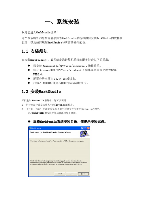
一、系统安装欢迎您进入MarkStudio世界!这个章节将告诉您如何着手操作MarkStudio系统和如何安装MarkStudio的软件和驱动,以及如何规划MarkStudio与所需的硬件配备。
1.1 安装须知在安装MarkStudio时,必须确定您计算机系统的配备符合以下的需求:◆已安装Windows2000/XP/Vista/windows7.0操作系统。
◆符合Windows2000/XP/Vista/windows7.0操作系统需求之硬件配备USB2.0。
◆屏幕分辨率须为1024*768或以上。
◆已插入MC8001/8016/7000打标运动控制卡。
1.2 安装MarkStudio开机进入Windows XP系统中,您可以利用1.执行光盘中或是文件夹中的[Setup.exe]程序。
2. [开始—执行] 的功能来执行光盘中或是文件夹中的[Setup.exe]程序。
进入MarkStudio的安装程序后会出现如下画面:◆选择MarkStudio系统安装目录,依提示安装完成。
启动MarkStudio。
在操作系统中[开始—程序]此工作列中会增加一个名称为MarkStudio激光打标系统的工作列,选择此工作列中的MarkStudio程序亦可启动系统。
1.3 安装硬件驱动驱动在安装目录下的Drivers里,比如默认的是(C:\ProgramFiles\Earain\MarkStudio\Drivers),插入MC8001/8017/7000后右下角会提示发现新硬件,然后会弹出如下窗口:点击是,仅这一次),点下一步。
点[从列表或是指定位置安装]。
点浏览,选中安装目录下的“Drivers”目录,再点”下一步”直到安装完成.安装完成,在设备管理器里会显示“MC8000 Card”字样.二、系统特点MarkStudio软件是一套能支持多种激光打标硬件之通用型激光打标系统,不论是CO2激光或YAG和半导体激光还是光纤(IPG/SPI)激光皆可支持,兼容的硬件可向激光系统厂商查询。
- 1、下载文档前请自行甄别文档内容的完整性,平台不提供额外的编辑、内容补充、找答案等附加服务。
- 2、"仅部分预览"的文档,不可在线预览部分如存在完整性等问题,可反馈申请退款(可完整预览的文档不适用该条件!)。
- 3、如文档侵犯您的权益,请联系客服反馈,我们会尽快为您处理(人工客服工作时间:9:00-18:30)。
编辑好了以后可以进行编译, 编辑好了以后可以进行编译,在终端上进入目录
$ cd /home/geekos-0.3.0/scripts/project0/build
编译
$ ake depend $ make
如果没有错误, build目录下会生成相应的磁盘 如果没有错误,在build目录下会生成相应的磁盘 文件,这里是fd.img fd.img. 文件,这里是fd.img.以后的项目可能还会生产 硬盘镜像文件diskc.img diskc.img. 硬盘镜像文件diskc.img.
西北工业大学计算机学院
西北工业大学计算机学院
Start_Kernel_Thread 函数
Kernel_Thread* struct Kernel_Thread* Start_Kernel_Thread( Thread_Start_Func startFunc, ulong_t arg, priority,bool int priority,bool detached) { Kernel_Thread* struct Kernel_Thread* kthread = Create_Thread(priority, detached); if (kthread != 0) { Setup_Kernel_Thread(kthread, startFunc, arg); Make_Runnable_Atomic(kthread); } return kthread; }
如:./startProject project0 ../src/project0
西北工业大学计算机学院
实验说明 然后我们可以使用桌面上的文件编辑器bluefish 然后我们可以使用桌面上的文件编辑器bluefish project0的源代码进行编辑 代码路径: 的源代码进行编辑. 对project0的源代码进行编辑.代码路径:
GeekOS操作系统实验 GeekOS操作系统实验 设计项目0 设计项目0
西北工业大学 计算机学院 刘尊
环境说明 我们采用的实验环境是
GeekOS bochs Fedora7 VMware windowsXP 硬件 GeekOS VMware Virtualization Native OS HW
西北工业大学计算机学院
GeekOS的可能运行环境 GeekOS的可能运行环境
GeekOS Bochs (HW Emulation) Native OS HW
GeekOS HW
实验说明 实验环境已经预先设置好了 首先打开程序中的VMware 然后在VMware VMware, VMware中打开 首先打开程序中的VMware,然后在VMware中打开 虚拟机,并启动该虚拟机,进入linux linux系统 虚拟机,并启动该虚拟机,进入linux系统 桌面上有终端, 桌面上有终端,文件浏览器和文件编辑器的快捷 方式可供大家使用 我们的工作目录是/home/geekos 0.3.0,该目录的 /home/geekos我们的工作目录是/home/geekos-0.3.0,该目录的 结构如前所示,仅根据需要添加了一个replace replace目 结构如前所示,仅根据需要添加了一个replace目 录 当要完成某项目时,首先在终端进入工作目录, 当要完成某项目时,首先在终端进入工作目录, 然后进入scripts目录, scripts目录 然后进入scripts目录,使用该目录中的脚本 startProject建立项目文件 startProject建立项目文件
实验说明 然后可以在bochs模拟器中查看运行结果 然后可以在bochs模拟器中查看运行结果 bochs Bochs模拟器的默认的配置文件叫.bochsrc,本来 模拟器的默认的配置文件叫.bochsrc, Bochs模拟器的默认的配置文件叫.bochsrc,本来 每个项目都配有一个这样的配置文件,但版本与 每个项目都配有一个这样的配置文件, bochs不符 所以首先要从我们增加的replace 不符, replace目 bochs不符,所以首先要从我们增加的replace目 录拷贝一个名为bochsrc的配置文件到build目录, bochsrc的配置文件到build目录 录拷贝一个名为bochsrc的配置文件到build目录, 并且在项目1中由于没有硬盘镜像文件, 并且在项目1中由于没有硬盘镜像文件,所以要把 bochsrc中的第12行 中的第12 bochsrc中的第12行
该函数的主要功能是以参数startFunc指向的代码为进程 该函数的主要功能是以参数startFunc指向的代码为进程 startFunc 体生成一个内核进程. 体生成一个内核进程. startFunc是一个Thread_Start_Func类型的函数指针 是一个Thread_Start_Func类型的函数指针, startFunc是一个Thread_Start_Func类型的函数指针,其 定义在kthread.h kthread.h中 定义在kthread.h中
西北工业大学计算机学院
项目分析 熟悉键盘操作函数,编程实现新建一个内核进程. 熟悉键盘操作函数,编程实现新建一个内核进程. 新建一个内核进程 该进程的功能是:接受键盘输入的字符并显示 键盘输入的字符并显示到 该进程的功能是:接受键盘输入的字符并显示到 屏幕,当输入ctrl+d ctrl+d时 屏幕,当输入ctrl+d时,结束进程 需要了解新建内核进程的方法 Start_Kernel_Thread函数 Start_Kernel_Thread函数 还需理解GeekOS GeekOS的键盘处理函数 还需理解GeekOS的键盘处理函数 还需要编写一个接收键盘输入并显示的函数
ata0-master:………. 用'#'注释掉
然后就可以运行bochs了 然后就可以运行bochs了 bochs $ bochs –f bochsrc f 如果能正确显示, 如果能正确显示,则实验成功
西北工业大学计算机学院
项目设计目的和要求 目的: 目的: 熟悉GeekOs的项目编译,调试和运行环境, GeekOs的项目编译 熟悉GeekOs的项目编译,调试和运行环境,掌握 GeekOs运行工作过程 GeekOs运行工作过程 要求: 要求: 搭建GeekOS的编译和调试平台,掌握GeekOS GeekOS的编译和调试平台 GeekOS的 1,搭建GeekOS的编译和调试平台,掌握GeekOS的 内核进程工作原理,完成系统的配置, 内核进程工作原理,完成系统的配置,调试 project0并添加输入字符并回显功能 project0并添加输入字符并回显功能 熟悉键盘操作函数, 2,熟悉键盘操作函数,编程实现新建一个内核进 该进程的功能是: 程.该进程的功能是:接受键盘输入的字符并显 示到屏幕,当输入ctrl+d ctrl+d时 结束进程. 示到屏幕,当输入ctrl+d时,结束进程.
TODO("Start a kernel thread to echo pressed keys and print counts");
提示在此处建立新进程
西北工业大学计算机学院
�
西北工业大学计算机学院
GeekOS的键盘处理函数 GeekOS的键盘处理函数 定义在keyboard.h和keyboard.c中 定义在keyboard.h和keyboard.c中. keyboard.h 定义了功能键常量,缓冲区等,请大家自行阅读, 定义了功能键常量,缓冲区等,请大家自行阅读, 其公用接口有三个Init_Keyboard Read_Key和 Init_Keyboard, 其公用接口有三个Init_Keyboard,Read_Key和 Wait_For_Key 键盘初始化是在Main函数中调用Init_Keyboard Main函数中调用Init_Keyboard实 键盘初始化是在Main函数中调用Init_Keyboard实 现的 Read_Key用来获取键值 Read_Key用来获取键值 Wait_For_Key用来等待键盘输入,进程若想获得 Wait_For_Key用来等待键盘输入, 用来等待键盘输入 键盘输入只要调用该函数即可, 键盘输入只要调用该函数即可,该函数返回 keycode类型 是在keyboard.h 类型, keyboard.h中定义的一个 keycode类型,是在keyboard.h中定义的一个 ushort_t
西北工业大学计算机学院
主要工作 编写一个函数,功能是: 编写一个函数,功能是:接受键盘输入的字符并显 示到屏幕,当输入ctrl+d ctrl+d时 示到屏幕,当输入ctrl+d时,结束进程 在main函数中调用Start_Kernel_Thread 函数,将 main函数中调用Start_Kernel_Thread 函数, 函数中调用 上边函数的地址传给参数startFunc startFunc, 上边函数的地址传给参数startFunc,建立一个内 核级进程 main函数中有 在main函数中有
