EKS Light 简单电子钥匙系统
EKS Profibus 在 Siemens S7-300 上读取 EKS 电子钥匙说明书

EKS Profibus on Siemens S7-300 – reading in EKS Electronic-KeysContentsComponents/modules used (2)EUCHNER (2)Others (2)Functional description (2)General (2)Example of an Electronic-Key structure (2)Setting the EKS Electronic-Key adapter (3)Profibus address (3)Write-protection setting (3)Configuration in the control system (4)Hardware (4)Programming in the control system (5)Global data blocks (5)STL program for retrieving the Electronic-Key content (6)Important note – please observe carefully! (10)Components/modules usedEUCHNERDescription Order no./item designationEKS Profibus 084800 / EKS-A-IDX-G01-ST09/03EKS Electronic-Key 077859 / EKS-A-K1RDWT32-EU084735 / EKS-A-K1BKWT32-EU091045 / EKS-A-K1BUWT32-EU094839 / EKS-A-K1GNWT32-EU094840 / EKS-A-K1YEWT32-EUTip: More information and downloads about the aforementioned EUCHNER products can be found at www.EUCHNER.de. Simply enter the order number in the search box.OthersDescription ItemS7-300, CPU 315F-2 PN/DP 6ES7315-2FJ14-0AB0Functional descriptionGeneralThe EKS is connected to a Siemens S7-300 PLC via the Profibus. All data corresponding to the data structure below should be read out.Example of an Electronic-Key structureThe data on the Electronic-Key are structured as follows:Byte no. Description Type Length Explanation103 – 104 KEYCRC CRC 2 bytes Checksum over a certain part of the Electronic-Key as copy protection.Refer to the EKM manual for details about the CRC.105 – 112Expiry date Date 8 bytes Electronic-Key expiry date.113 – 114 Authorization level Word 2 bytes Authorization level for access to the machine.115 Department Byte 1 byte Number describing a limited quantity of machines or installations.116 – 123 KeyID KeyID 8 bytes The KeyID is a number that is permanently pre-programmed on theElectronic-Key by EUCHNER. This number is different for each Electron-ic-Key. This number can be used to identify workers.The structure corresponds to application example AP000169-2…Setting the EKS Electronic-Key adapterProfibus addressThe device must be set to address 75. Address 75 is 1001011 in binary notation. DIP switches 1 to 7 are set accordingly (DIP switch 1 is the least significant bit).Figure 1Write-protection settingThe device is configured only for reading. Correspondingly, DIP switch 8 is set to ON.Figure 2Configuration in the control systemHardwareSimatic Manager version 5.5+SP1 is used for configuration. To perform parameter assignment for EKS on the Profibus, drag the object “EKS-A-IDX-G01-ST09/03” to the Profibus, followed by the “Read/Write: 32 Byte” module to the first slot. The address range can remain set at 256 to 287. The size of 32 bytes is selected because a total of 21 bytes of user data, including the KeyID, are to be retrieved. An adequately large input range must be reserved in the control system for this purpose.When a new Electronic-Key is inserted, the data are always read automatically from byte 0. As the user data are located at the end of the Electronic-Key instead of at the start in this example, the actual user data are loaded in a read routine in the sequential pro-gram. The KeyID is retrieved at the same time.Figure 3Set address 75 in the properties for the Profinet interface of the DP slave, matching the settings on the DIP switches. You set the subnet parameters according to your bus system.Figure 3Programming in the control systemGlobal data blocksData blocks are created for saving the transmitted and received data for the EKS.The data are created in a structured manner in data block DB1 for reading, with all data items longer than one byte being created as individual bytes to circumvent the even-numbered alignment in the control system. The data block must be the same length as the input range of the EKS, otherwise the system function for reading will not work.DB1, ReadBufferEKSFigure 4As a command has to be sent to the EKS so that the data from byte No. 103 and the KeyID can be read, the data required for this purpose are located at the start of data block DB2. The same data range of the EKS Electronic-Key is always read. The data block is suitably pre-filled during initialization. These are the bytes WriteCommand (64(dec.)), WriteStartAddress (103(dec.)) and WriteNumberBytes (21(dec.)). The data block must be the same length as the output range of the EKS, otherwise the system func-tion for writing will not work.DB2, WriteBufferEKSFigure 5DB10, instance module for FB1As the function module FB1 operates with static variables, a DB must be used as an instance module. In the example, DB10 is created for this purpose.STL program for retrieving the Electronic-Key contentThe reading program is programmed in FB1 in this example. The program reads only when an Electronic-Key is inserted and new data are ready. An Electronic-Key that has been read in once will not be read in again. The data from byte 103 (KeyCRC), including the KeyID, are read and are provided in data block DB1 from byte 4 for further processing. 21 bytes of user data in total are re-trieved from the EKS Electronic-Key.The status bytes of the EKS are saved in bytes 0 to 3 of DB1.Description of the interfaceInput dataNone.Output dataError message, new Electronic-Key and status of the DP slave.Input/output dataNone.Static dataThe counter value of the EKS is created statically. This value is compared with the value read by the EKS. Data are retrieved only if both values differ.Temporary dataNone.Changed registersA1, A2, SWUnchanged registersAR1, AR2, DBR1, DBR2System functions usedSFC14, DPRD_DAT – read standard DP slaves/PROFINET IO devicesSFC15, DPWR_DAT – write standard DP slaves/PROFINET IO devicesGlobal dataData blocks DB1 and DB2 with a minimum size of 32 bytes each are assumed.The content of data block DB1 is completely overwritten.The first three bytes (command byte, EKS address and length of the user data) are overwritten in data block DB2.Symbol tableFigure 8STL program in FB1- ReadEKS//Check of whether EKS is ready. If not: end of block.UN "EKSactive"; // EKS readyBEB ;NETWORKTITLE =Check whether Electronic-Key insertedUN "EKSIn"; // Check whether an Electronic-Key is insertedSPB RES;NETWORKTITLE =Electronic-Key inserted//Check whether Electronic-Key is new.L #KeyCount; // Already read if same value is contained in the key counter L "EKSInCount"; // Current counter value in EKS==I ; // Compare only if counter value in EKS is higherSPBN ZS; // Retrieve data only with new Electronic-KeyR #Error; // Feedback, no errorR #NewKey; // Feedback, no Electronic-KeyBE ;Figure 9aNETWORKTITLE =Start cycle sequence to read the Electronic-Key data//Start of the actual reading routine from a newly inserted Electronic-Key.//Cycle sequence.ZS: L #CycleMarker;SPL NEXT;SPA z1; // 1st cycle: set Read commandSPA z2; // 2nd cycle: reset Read commandSPA z3; // 3rd cycle: read dataNEXT: BEA ;NETWORKTITLE =1st cycle//Transfer of parameters to the EKS so that the range from byte 103,//including the KeyID, is sent.//The transmit-data range is already pre-allocated in DB2 by initialization and//does not have to be written again.//The command must be set in each case.z1: U "EKSJobactive"; //Wait until no job is activeUN "EKSJobDone"; //and job is doneBEB ;L 64; // Set Read command from Electronic-Key byte 103 with 21 bytesT "WriteBufferEKS".WriteCommand;L 103;T "WriteBufferEKS".WriteStartAddress;L 21;T "WriteBufferEKS".WriteNumberBytes;L 1;T #CycleMarker; // Prepare cycle marker for the next cycleCALL "DPWR_DAT" ( // Call of SFC 15 DPWR_DATLADDR := W#16#100, // Address of the EKS memory rangeRECORD:= P#DB2.DBX0.0 BYTE 32, // Start address of the DB, length must be 32RET_VAL := MW 1); // Feedback// Check whether an error occurredL MW 1; // Write feedback from ProfibusL 0; // Only return value 0 is OK==I ;SPBN MERR; // If a value <> 0 was returned: errorBEA ;Figure 9bNETWORKTITLE =2nd cycle//Reset of the Read commandz2: UN "EKSJobactive"; // Wait until job is active andU "EKSJobDone"; // job not ended, then reset of the Read commandBEB ;L 0; // Reset of the Read commandT "WriteBufferEKS".WriteCommand;L 2;T #CycleMarker; // Prepare cycle marker for next cycleCALL "DPWR_DAT" ( // Call of SFC 15 DPWR_DATLADDR := W#16#100, // Address of the EKS memory rangeRECORD := P#DB2.DBX0.0 BYTE 32,// Start address of the DB to be sent, length must be 32 RET_VAL := MW 1); // Feedback//Check whether error occurredL MW 1; // Write feedback from ProfibusL 0; // Only return value 0 is OK==I ;SPBN MERR; // If a value <> 0 was returned: errorBEA ;Figure 9cNETWORKTITLE =3rd cycle//Reading of the Electronic-Key data.//z3: U "EKSJobactive"; // Wait until no job is activeUN "EKSJobDone"; // and job is doneBEB ;CALL "DPRD_DAT" ( // Call of SFC 14 DPRD_DATLADDR := W#16#100, // Address of the EKS memory rangeRET_VAL := MW 1, // FeedbackRECORD := P#DB1.DBX0.0 BYTE 32);// Start address of the DB for reception, length must be 32 L 0;T #CycleMarker;//Check whether error occurredL MW 1; // Read feedback from ProfibusL 0; // Only return value 0 is OK==I ;SPBN MERR; // If a value <> 0 was returned: error//Electronic-Key read completely, the data are now in DB1L "EKSInCount"; // Read out current counter value from EKST #KeyCount; // Note that reading was complete with this counter valueS #NewKey; // Report back that a new Electronic-Key was read completelyR #Error; // No errorBEA ;Figure 9dNETWORKTITLE =Error processingMERR: L MW 1;T #DPStatus; // DP status as feedback in case of errorS #Error; // Return value = 1, error occurredR #NewKey; // Feedback, no Electronic-KeyL 0;T #CycleMarker; // Reset cycle sequenceBE ;NETWORKTITLE =ResetRES: R #Error; // No errorR #NewKey; // Feedback, no Electronic-KeyL 0;T #CycleMarker; // Reset cycle sequenceFigure 9eFB1 call//Retrieval of data from the EKS Electronic-KeyCALL "Read EKS" , "Data FB1"Error :=M0.0 // Return value for errorNewKey :=M0.1 // Return value, whether new Electronic-KeyDPStatus:=#Status // Status of the DP slaveU M 0.0 // Check whether error occurredSPB MERR // If values = 1, jump to error routineFigure 10Important note – please observe carefully!This document is intended for a design engineer who possesses the requisite knowledge in safety engineering and knows the ap-plicable standards, e.g. through training for qualification as a safety engineer. Only with the appropriate qualification is it possible to integrate the introduced example into a complete safety chain.The example represents only part of a complete safety chain and does not fulfill any safety function on its own. In order to fulfill a safety function, the energy switch-off function for the hazard location and the software within the safety evaluation must also be considered, for example.The introduced applications are only examples for solving certain safety tasks for protecting safety doors. The examples cannot be comprehensive due to the application-dependent and individual protection goals within a machine/installation.If questions concerning this example remain open, please contact us directly.In accordance with Machinery Directive 2006/42/EC, the design engineer of a machine or installation is obligated to perform a risk assessment and take measures to reduce the risk. When doing this, the engineer must comply with the applicable national and international standards. Standards generally represent the current state of the art. Therefore, the design engineer should continu-ously inform himself about changes in the standards and adapt his considerations to them. Relevant standards include EN ISO 13849 and EN 62061. This application must be regarded only as assistance for the considerations about safety measures.The design engineer of a machine/installation is obligated to assess the safety technology itself. The examples must not be used for assessment, because only a small excerpt of a complete safety function was considered in terms of safety engineering here. In order to be able to use the safety switch applications correctly on safety doors, it is indispensable to observe the standards EN ISO 13849-1, EN ISO 14119 and all relevant C-standards for the respective machine type. Under no circumstances does this doc-ument replace the engineer’s own risk assessment, and it cannot serve as the basis for a fault assessment.Particularly in case of fault exclusion, it must be noted that this can be performed only by the design engineer of a machine or installation and requires a reason. General fault exclusion is not possible. More information about fault exclusion can be found in EN ISO 13849-2.Changes to products or within assemblies from third-party suppliers used in this example can lead to the function no longer being ensured or the safety assessment having to be adapted. In any event, the information in the operating instructions on the part of EUCHNER, as well as on the part of third-party suppliers, must be used as the basis before this application is integrated into an overall safety function. If contradictions should arise between the operating instructions and this document, please contact us directly.Use of brand names and company namesAll brand names and company names stated are the property of the related manufacturer. They are used only for the clear identifi-cation of compatible peripheral devices and operating environments in relation to our products.EUCHNER GmbH + Co. KG · Kohlhammerstraße 16 · 70771 Leinfelden-EchterdingenTelephone:+497117597-0·Fax:+497117597-303·***************·www.euchner.de。
纺织英语电子版

viable\’vai bl\能生存的 entity\’entiti\实体 upgrade\, p ’greid\使升级 adept\’ dept\能手,内行 discard\diska:d\丢弃 sizeable\’saiz bl\ 相当大的 economy of scale\skeil\规摸经济 spunbond 纺黏法 meltblown 熔喷法 vitality\vai ’t l ti\生命力
volume growth\’v lju:m g u \大量增长 latex binder\’leiteks ‘b \胶乳黏合剂 entrench \in ’trent \牢固地确立 diaper\’dai p \ 尿布
absorbent liner\ b ’s :b nt\卫生巾的吸液衬里 face mask\feis ma:sk\面罩 geotextile 土工织物
laid down\leid daun\ 铺放 air laid\leid\气流成 网
dry laid \drai leid\ 干法成 网 wet laid \wet leid\ 湿法成 网
vinyl chloride\’vainil ‘kl :raid\ 氯 乙烯 ultrasonically\, ltr ’s n kli\使用超声波地 barbed needle\ba:bd\
带有倒刺 的针 needlepunch\’ r mid\针刺 spunlace 水刺 stitchbond 缝编 aramid \eir mid\芳纶
superabsorbent\’sju:p b ’s :b nt\超吸湿性的 granule\’gr nju:l\颗粒。
安士能产品简介
产品简介 安士能公司的成功故事始于1940年,由公司创始人艾米 · 安士能先生创立的工程技术公司。
1952年,世界上第一个组合行程开关的发明奠定了公司发展的第一个里程碑。
创新的技术理念,使这款产品成为机床加工工业的亲密伙伴,被应用于机械定位与控制系统。
这种创新理念,今天依然是这个家族企业的企业精神,并引以为豪。
人,机器与过程的安全防护是现代安士能公司主要的生产与服务理念。
也就是说,我们的安全产品都将秉承这个宗旨,最大限度的降低人与机器有可能产生的危险以及操作过程中不必要的损失。
我们的最大目标是客户100%的满意,和我们员工良好的福利。
质量、可靠、精密是我们企业文化的精髓。
基于我们员工的长期实践经验和革新精神,我们总能够为客户的各种特殊要求提供解决的方案和产品。
我们的销售网络遍布全球,七家位于欧洲,北美和亚洲各设有两家,并在印度成立了合资公司及二十三个代表处。
除了位于莱恩费尔登(Leinfelden)的公司总部和位于乌恩特博林根(Unterboehringen)的生产工厂,安士能公司还在中国成功建立了组装工厂。
持续的创新与革新操纵杆开关,电子手轮,手持操作单元,电子钥匙系统操纵杆开关,电子手轮,手持操作单元,电子钥匙系统,电子钥匙系统管理软件内 容行程开关,精密单体行程开关,精密组合行程开关感应识别系统,导轨/挡块,单孔固定行程开关圆型接插件自动化安全开关,金属壳体无锁止功能,带锁止功能带锁止监控功能,安全门铰链行程开关带安全功能电子编码器,磁性编码器带锁止监控功能,电磁线圈安 全安全开关,塑料壳体无锁止功能,行程开关带安全功能带锁止监控功能,拉索开关非接触安全开关授权开关安全门闩授权开关,安全门闩带总线接口的安全产品,安全继电器带总线接口的安全产品安全继电器,安全模块人机设备1952年,安士能公司发明了第一个组合行程开关。
通过持续不断的改进与发展,自动化系列今天依然是安士能公司众多产品的重要组成部分,高品质的材料,坚固美观的壳体,以及安士能一贯的高品质,高可靠型和精密的特点,使其成为机械与系统工程领域内理想的机电控制产品。
ekey home 使用说明书

ekey home zh使用说明书原版使用说明书的译文 - ID 172/494/0/611目录概述 (3)阅读提示 (3)产品责任和责任限定 (3)担保和制造商质保 (3)提示、符号和缩写 (3)安全提示 (4)电流会造成生命危险 (4)防擅自操作的安全性 (4)产品说明 (5)系统概览 (5)供货范围 (5)按规定使用和应用领域 (5)指纹扫描器 (6)控制单元 (8)技术数据 (10)安装和调试 (11)输入安全代码 (12)修改安全代码 (12)设置继电器切换时间 (13)执行测试模式 (14)设置 LED 亮度 (16)设置数字输入端 (17)存入手指 (18)应用 (20)开门 (20)删除用户 (20)展示模式 (21)调出系列号和版本号 (21)将系统恢复出厂设置 (23)软件升级 (23)错误显示和排除 (24)保养 (24)废弃处理 (24)一致性声明 (25)zh│1版权 (25)2│zh概述本说明书是产品的一部分。
请妥善保管。
如需更多关于产品的信息,请联系您的专业经销商。
在以下情况中可能会影响设备的安全运行和功能。
这种情况下,由运营商/用户承担因功能故障而导致的责任:□未按说明书安装、使用、维护和清洁系统设备;□在按规定使用的范围外使用系统设备;□在系统设备上进行未获运营商授权的修改。
本使用说明书没有修改服务。
保留光学和技术修改的权利,不完全排除内容错误、排版和打印错误。
通常参照我们的一般贸易和交货条件(购买产品时的有效版本)。
参见.提示、符号和缩写表示进一步的信息和有用的提示。
表示直接的危险情况,会导致死亡或重伤。
表示可能的财产损失,不会出现人身伤害。
阅读提示产品责任和责任限定担保和制造商质保zh│34│zh符号:1. 逐步的操作指示 参考本说明书的段落参考装配说明书 参考布线平面图□ 无固定顺序的列表,第 1层级显示值 ekey home 指纹扫描器嵌装产品名称 菜单项 菜单项 按键按键缩写和术语:AR arteFAR False Acceptance Rate 错误接受率 FRR False Rejection Rate 错误拒绝率 FS 指纹扫描器 IN integraSE 控制单元指纹图案通过指纹图案获取的生物统计信息安全提示所有ekey home设备均用保护低电压运行。
领世达 KH100 全功能钥匙助手 用户手册说明书

KH100全功能钥匙助手用户手册★使用前请仔细阅读完本使用说明书KH100版权所有领世达对其发行的或与合作公司共同发行的包括但不限产品或服务的全部内容及领世达所属相关网站上的材料、软件等拥有版权等知识产权,受法律保护。
未经本公司书面许可,任何单位及个人不得以任何方式或理由对上述产品、服务、信息、材料的任何部分进行拷贝、修改、抄录、传播或与其他产品捆绑使用、销售等。
凡侵犯本公司版权等知识产权的,我司必依法追究其法律责任!产品领世达KH100全功能钥匙助手及其相关资料仅用于汽车正常维修、诊断及检测,切勿用于违法违规行为。
若因使用我司产品触犯法律法规,本公司不承担任何法律责任。
本产品有一定的可靠性,但不排除可能产生的损失和破坏,对此产生的风险由用户自行承担,本公司不承担任何风险及责任。
声明单位:领世达法律事务部安全须知使用此产品前,请阅读本节信息,并了解这些信息。
有关更详细的信息,请参阅附录的“安全须知事项”。
1、请勿撞击、扔掷、针刺本产品,并避免跌落、挤压、弯曲。
2、请勿在浴室等潮湿的环境中使用本产品,并避免本产品被液体浸湿或冲洗。
在禁止使用本产品的场所,或者使用本产品会引起干扰或危险时,请关闭本产品。
3、请勿在驾驶汽车时使用本产品,以免妨碍安全驾驶。
4、在医疗场所,请遵守有关规定或条例。
在靠近医疗设备的区域,请关闭本产品。
5、在使用高精度的电子设备附近,请关闭本产品,否则可能导致电子设备故障。
6、请勿擅自拆卸本产品及附件,只有授权机构才可维修。
7、请勿将本产品及附件放置于具有强大电磁场的器具中。
8、请将本产品远离磁性设备,磁性设备的辐射会抹掉本产品上存储的信息。
9、请勿在高温处、有易燃气体的地方(如加油站附近)使用本产品。
10、使用本产品时,请遵守相关法律法规,并尊重他人隐私及合法权利。
目录版权声明 (2)安全须知 (3)目录 (4)第一章.注册引导 (4)第二章.产品概述 (5)2.1产品介绍 (5)2.2产品特色 (5)2.3产品参数 (5)2.4整机介绍 (6)2.5功能介绍 (7)2.5.1识别拷贝 (7)2.5.2门禁车库 (7)2.5.3芯片模拟 (8)2.5.4芯片模拟 (8)2.5.1芯片生成 (8)2.5.2遥控生成 (9)2.5.3智能卡生成 (9)2.5.4线圈识别 (9)2.5.4遥控功能 (10)2.5.4特殊功能 (10)2.6升级 (11)第三章.售后服务 (11)保修服务卡 (13)第一章:注册引导注:开机后,请连接好WIFI,进入注册流程。
Skytech TM R-AF1-1 单功能无线遥控系统说明书

Model: TM/R-AF1-1INSTALLATION AND OPERATING INSTRUCTIONSSINGLE-FUNCTION WIRELESS REMOTE CONTROL SYSTEM FOR OPERATING VALVES WITH ON/OFF LATCHING SOLENOIDSINTRODUCTIONThis SKYTECH remote Wireless Wall Timer system was developed to provide safe, reliable, and user-friendly remote control system for gas heating appliances. The system can be operated manually from the transmitter. The system operates on one of 65,536 security codes that are programmed into the transmitter at the factory.WALL TIMERThe wall timer operates on a (2) 3V button cell batteries (included) made specifically for remote controls and electronic lighters. Before using the wall transmitter, install the two (2) 3V button cell batteries. Follow instructions below.The wall timer has a 30 min, 60 min, 120 min, and OFF buttons. When any of the buttons on the wall timer is pressed, a signal light on the wall timer illuminates briefly to verify that a signal has been sent. If the signal light does not illuminate, check the batteries. Upon initial use, there may be a delay of 5-seconds before the remote receiver will respond to the wall timer.TO INSTALL BATTERIES1. Remove face from backing plate by insetting a small screwdriver into the small slot at the top or bottom of the faceplate as shown below then snap OFF.2. Locate the (2) holders for the 3V button cell batteries.3. Place the button cell batteries into the battery holders and snap into place. (Make sure that the batteries are installed with the (+) plus side as shown to the right.4. After the batteries are installed replace the faceplate on the base.TO REMOVE THE BATTERIES1. Remove face from backing plate by insetting a small screwdriver into the small slot on the side at the top or bottom of the faceplate as shown to the right then snap OFF.2. Locate the (2) holders for the 3V button cell batteries.3. Insert a small screwdriver into the slot at the button cell battery and pop the battery out (Slots shown in picture above).4. After the batteries are installed replace the faceplate.IF YOU CANNOT READ OR UNDERSTAND THESE INSTALLATION INSTRUCTIONS DO NOT ATTEMPT TO INSTALL OR OPERATEWALL MOUNTING THE TIMER 1. Remove face from backing plate by insetting a small screwdriver into the small slot at the top or bottom of the faceplate as shown to the right then snap OFF. 2. Locate the (2) two mounting holes and mark the holes on the wall. 3. Use the (2) two dry wall anchors and screws (that are supplied) to mount the base plate to the wall as shown. 4. The wall transmitter can also be mounted onto an existing (Plastic) electrical box. 5. Base plate should be mounted level on the wall for best operation.REMOTE RECEIVERIMPORTANTTHE REMOTE RECEIVER SHOULD BE POSITIONED WHERE AMBIENTTEMPERATURES DO NOT EXCEED 130° F.The remote receiver (right) operates on (4) 1.5-volt AA batteries. It isrecommended that ALKALINE batteries be used for longer battery life and maximum microprocessor performance. IMPORTANT: New or fully charged batteries are essential to proper operation of the remote receiver as a latchingsolenoid power consumption is substantially higher than standard remote controlsystems.NOTE : The remote receiver will only respond to the transmitter when the 3-position slide button on the remote receiver is in theREMOTE position. The remote receiver houses the microprocessor that responds to commands from the transmitter to control system operation.FUNCTIONS:1. With the slide switch in the REMOTE position, the system will onlyoperate if the remote receiver receives commands from the transmitter. Upon initial use or after an extended period of no use, the ON button may have to be pressed for up to three seconds before activating solenoid. If the system does not respond to the transmitter on initial use, see LEARNING TRANSMITTER TO RECEIVER section. 2. Slide switch to ON for manual operation.3. With the slide in the OFF position, the system is OFF.4. It is suggested that the slide switch be placed in the OFF position ifyou will be away from your home for an extended period of time.Placing the slide switch in the OFF position also functions as a safety "lock out" by both turning the system OFF and rendering the transmitter inoperative.INSTALLATION INSTRUCTIONSWARNINGDO NOT CONNECT REMOTE RECEIVER DIRECTLY TO 110-120VAC POWER. THIS WILLBURNOUTTHE RECEIVER. FOLLOW INSTRUCTIONS FROM MANUFACTURER OF GAS VALVE FOR CORRECT WIRING PROCEDURES. IMPROPER INSTALLATION OF ELECTRIC COMPONENTS CAN CAUSE DAMAGE TO GAS VALVE AND REMOTE RECEIVER.INSTALLATIONThe remote receiver can be mounted on or near the fireplace hearth. PROTECTION FROM EXTREME HEAT IS VERY IMPORTANT. Like any piece of electronic equipment, the remote receiver should be kept away from temperatures exceeding 130º F inside the receiver case. Battery life is also significantly shortened if batteries are exposed to high temperatures.Make sure the remote receiver switch is in the OFF position. For best results it is recommended that 18 gauge stranded wires should be used to make connections and no longer than 20-feet.WIRING INSTRUCTIONSCONNECTING THE RECEIVER TO A VALVE WITH THE LATCHING SOLENOID1. Connect the BLACK 18 gage stranded wire with the 1/4’ female terminal from the receiver to the BLACK wire with the 1/4” maleterminals from the valve solenoid.2. Connect the RED 18 gage stranded wire with the 1/4’ female terminal from the receiver to the RED wire with the 1/4” male terminalsfrom the valve solenoid.3. After receiver wires are connected to the valve solenoid wire make sure the receiver shield is located over the receiver and thenlocate the receiver in an area that will not exceed the 130° F.IMPORTANT NOTE: Operation of these controls is dependent on which wire is attached to which terminal. If operation of controldoes not correspond to operating buttons on transmitter, reverse wire installation at the receiver or at the control.NOTE: Up to 6.3 VDC of power is provided at the receiver terminal.GENERAL INFORMATIONLEARNING TRANSMITTER TO RECEIVEREach transmitter uses a unique security code. It will be necessary to press the LEARN button on the receiver to accept the transmitter security code upon initial use, if batteries are replaced, or if a replacement transmitter is purchased from your dealer or the factory. In order for the receiver to accept the transmitter security code, be sure the slide button on the receiver is in the REMOTE position; the receiver will not LEARN if the slide switch is in the ON or OFF position. The LEARN button in located on the front face of the receiver; inside the small hole labeled LEARN. Using a small screwdriver or end of a paperclip gently Press and Release the black LEARN button inside the hole. When you release the LEARN button the receiver will emit an audible “beep”. After the receiver emits the beep press ANY transmitter button and release. The receiver will emit several beeps indicating that the transmitter’s code has been accepted into the receiver.The microprocessor that controls the security code matching procedure is controlled by a timing function. If you are unsuccessful in matching the security code on the first attempt, wait 1 - 2 minutes before trying again--this delay allows the microprocessor to reset its timer circuitry--and try up to two or three more times.OPERATION4. This remote control will operate the gas valves latching solenoid to open the gas flow to full ON.5. When the ON button is depressed the transmitter sends a RF signal to the receiver. The receiver then sends apulse of 6-volts of power to the solenoid. The solenoid then opens the gas flow to the burner then to full ON.6. When the OFF button is depressed the transmitter sends a RF signal to the receiver. The receiver then sends apulse of 6-volts of power to the solenoid. The solenoid then closes the gas flow to the burner then to full OFF.7. The remote control will only work with the hand held transmitter. The receiver slide switch is only for positive OFF or REMOTEoperation.NOTE: Extensive use of the Latching Solenoid (ON/OFF) will reduce the receiver's battery life significantly.BATTERY LIFELife expectancy of the alkaline batteries in the TM/R-AF1 can be up to 12 months depending on use of the solenoid function. Replace all batteries annually. When the transmitter no longer operates the remote receiver from a distance it did previously (i.e., the transmitter's range has decreased) or the remote receiver does not function at all, the batteries should be checked. It is important that the remote receiver batteries are fully charged, providing combined output voltage of at least 5.0 volts. The transmitter should operate with as little as 2.4 volts battery power. NOTE: Extensive use of the Solenoid will reduce the receiver's battery life significantly.TROUBLE SHOOTINGIf you encounter problems with your fireplace system, the problem may be with the fireplace itself or it could be with the TM/R-AF1 remote system. Review the fireplace manufacturer's operation manual to make sure all connections are properly made. Then check the operation of the remote in the following manner:1. Make sure the batteries are correctly installed in the RECEIVER. One reversed battery will keep receiver from operating properly.2. Check battery in TRANSMITTER to ensure contacts are touching (+) and (-) ends of battery. Bend metal contacts in for tighter fit.3. Be sure RECEIVER and TRANSMITTER are within 20 to 25-foot operating range.4. Keep RECEIVER from temperatures exceeding 120° F. Battery life shortened when ambient temperatures are above 115° F.5. If RECEIVER is installed in tightly enclosed metal surround, the operating distance will be shortened.NOTE:1. Heat conditions can cause batteries to discharge when temperatures exceed 1150 F. Studies show that alkaline batteries, whenexposed to a constant temperature of 1200 F, can lose up to 50% of their operating power. When the battery cools down, it will partially recharge itself, but constant heating and cooling will reduce the battery’s normal life expectancy. SPECIFICATIONSBATTERIES: Transmitter 12V - (A23)Remote Receiver 6V - 4 ea. AA 1.5 Alkaline FCC ID No.'s: transmitter - K9LTMR2A; receiver - K9L330IRX Operating Frequency: 303.8 MHZ Canadian ISC ID No.'s: transmitter – 2439A-TMR2A; receiver – 2439A 3301RX FCC REQUIREMENTSNOTE: THE MANUFACTURER IS NOT RESPONSIBLE FOR ANY RADIO OR TV INTERFERENCE CAUSED BY UNAUTHORIZED MODIFICATIONS TO THIS EQUIPMENT. SUCH MODIFICATIONS COULD VOID THE USER’S AUTHORITY TO OPERATE THE EQUIPMENT.FOR TECHNICAL SERVICE, CALL: U. S. INQUIRIES CANADIAN INQUIRIES(855) 498-8324 or (260) 459-1703 (877) 472-3923For Sales: (888) 672-8929WEBSITE: MANUFACTURED EXCLUSIVELY FOR SKYTECH II, Inc。
门锁接口图文版

门锁接口配置说明(图文版)目录爱迪尔门锁系统(V7.1)........................................................................................... 3 一、爱迪尔门锁系统二、Lock2200 .. (4)爱迪尔门锁系统Lock3200K .................................................................................... 三、 5普蓝德门锁系统.四、 (5)普蓝德门锁系统(IC)五、 (5)华联杰门锁系统....................................................................................................... 5 六、华联杰门锁系统(标准版)七、 (6)天宇门锁系统八、 (6)天宇第三代IC门锁管理系统 V3.0B ..................................................................... 九、6摩德隆门锁系统– RF ........................................................................................... 6 十、摩德隆门锁系统– IC........................................................................................... 7 十一、摩德隆门锁系统(十二、2008、2010专业版C).. (8)摩德隆门锁系统(2010专业版A)....................................................................... 8 十三、HMS十四、门锁系统(中国智能门锁系统). (10)必达门锁系统十五、5.5(doorlock-client(bt5.5)) (10)必达门锁系统5.6十六、 (10)必达门锁系统5.7 .................................................................................................. 十七、11必达门锁系统5.7A十八、 (12)中星门锁系统十九、......................................................................................................... 1 2高士达门锁系统. 二十、 (12)创佳门锁系统(RF) (LocstarDoorlock)......................................................... 1二十一、23 .................................................. 1(LocstarDoorlock)二十二、创佳门锁系统(老版IC) 3 LocstarDoorlock)....................................... 二十三、1新版)同创新佳智能门锁(RF-(......................................................................................................... 1二十四、3 邦威门锁系统13 ........................................................................................................ 索高门锁系统二十五、. 3 盾牌智能卡门锁系统二十六、............................................................................................. 1 二十七、(IC) ............................................................................................. 14 爱莱特门锁系统 4 二十八、....................................................................... 1深圳金联山门锁(HotelDoorlock)14 二十九、(LcDoorlock)宇达智能门锁.................................................................................4 T-2008(TemicDoorlock)Digital数码门锁三十、....................................................... 1 Digital 数码门锁T-2009(TemicDoorlock)5 三十一、. (1)5 (DigiICDoorlock)2.1.6)............................... 三十二、1Digital数码门锁(接口版本15 ................................................................................ 威萨门锁(WeisaDoorlock三十三、)08威萨门锁(Weisa08Doorlock)1三十四、6 ......................................................................6 .............................. V11-120601威萨电子门锁(三十五、WeisaV11M1Doorlock(V2))117 .................................................................. V3.01(LarkDoorlock)远为智能门锁三十六、远为智能门锁1V1.03 (IssueInterfaceLarkDoorlock)-新版.......................... 8 三十七、8 1................................................................... (RfwrDoorlock)智能门锁MCPO美高三十八、.三十九、西容接触式门锁5.09(SyronDoorlock) (19)四十、西容接触式门锁7.01(Syron504EWRDoorlock) (19)四十一、力维门锁接口(LevelDoorlock) (19)四十二、力维RF57门锁接口(LevelV1RFDoorlock) (20)四十三、力维V2.9门锁接口(LevelV29Doorlock) (20)四十四、Hotel1.1门锁系统(TmcardDoorlock) (20)四十五、ProUSB门锁系统(ProusbDoorlock) (20)四十六、Hotel Management(Es200601)门锁(Es200601Doorlock) (21)四十七、安达信门锁接口(ADXLock10Doorlock) (21)四十八、宏力佳智能门锁系统(HotelV1Doorlock) (21)四十九、阳光门锁(Uga2007Doorlock) (22)五十、GFOX V8.00C1门锁(KxLockDoorlock) (22)五十一、雅迪顿3.2门锁(2006版)(YDD2006Doorlock) (22)五十二、雅迪顿3.2门锁(YDD2008Doorlock) (24)五十三、西容2010版本新接口 (24)五十四、宝迅达V5门锁(XeederDoorlock) (24)五十五、同飞达门锁系统9.0 (IcreaderDoorlock) (25)五十六、广东网讯5.0门锁(T307Doorlock) (25)五十七、MB Temic 4.2门锁系统(Mbt2005Doorlock) (25)五十八、华高(HG)V9门锁系统(V9RFL32Doorlock) (25)五十九、兆凯RF380门锁系统 (27)六十、瑞威V8.9门锁系统 (27)六十一、天固门锁(AnLock2009Doorlock) (28)六十二、安洛克门锁(AnLock_2009Doorlock) (28)六十三、摩力门锁(MoliDoorlock) (29)六十四、劲卫门门锁系统(JWMDoorlock) (31)六十五、MF门锁(NetPmsDoorlock) (32)六十六、科裕门锁系统(IC_D5Doorlock) (33)六十七、科裕HUNERF-RF54门锁(HUNERFDoorlock) (33)六十八、科裕HUNERF-V20门锁(HUNERFV20Doorlock) (35)六十九、深圳日翔门锁系统(RFL32Doorlock) (37)七十、倍特门锁系统(BteDoorlock) (39)七十一、阔道门锁系统(LibDriverDoorlock) (41)七十二、Sccicc上成宾馆门锁管理系统(ScciccDoorlock) (41)七十三、三环智能TM卡锁系统(PbtmDoorlock) (43)七十四、三环智能门锁(CardDllDoorlock) (43)七十五、东屋电气Talenca门锁系统(TalencaDoorlock) (43)七十六、高盾(GoodDum)门锁(LockSDKDoorLock) (45)附:全功能门锁接口配置说明 (45)一、爱迪尔门锁系统(V7.1)1.配置说明1)数据库服务器:看门锁软件的数据库在哪,本机用127.0.0.12)门锁软件:选择使用的门锁软件3)串口:参照门锁软件的设置4)发卡机:参考门锁软件的设置5)TM发卡机类型:参考门锁软件的设置2.门锁房号设置参照门锁系统的房号设置,共6位。
凯利智能酒店M1感应门锁管理系统方案
凯利智能酒店M1感应门锁管理系统方案------------------------------------------作者------------------------------------------日期门锁管理系统方案项目名称:酒店门锁管理系统方案编号:提交单位:凯利智能时间:年月日第一章 公司简介产和销售,从事“智能电子产品系列化”的技术开发、设计、市场推广和应用的专业公司。
目前,凯利智能产品的用户遍布全国,涉及政府机关、邮电部门、旅游饭店、旅行社、投资公司等。
在酒店行业中树立良好声誉,客户队伍不断扩大,产品得到不断完善和发展。
凯利智能推出“智能一卡通电子门锁系统”,秉承多年来国内酒店门锁经验,以其精致豪华的外观设计加上高新技术,即可开门又可在酒店内作信用卡,实现管理消费一卡通。
现有磁卡、接触式✋卡、感应式✋卡等。
我公司拥有专业的✋卡电子门锁制造工厂和一支经验丰富的工程师队伍和从事酒店管理及酒店电脑网络系统开发、应用的专业人员,可为用户提供到厂家级免费保修壹年,终身维护服务。
凯利智能是国内做酒店电子行业最著名、最具实力的、技术力量最雄厚的专业公司之一,可为用户提供一整套从方案设计、设备选型、软件开发到对酒店人员系统化培训的一条龙服务。
我们深信:用户满意 企业利润!公司经营中始终把用户满意和技术服务放在第一位,这是公司生存的根本。
把公司的利益和用户的利益视为一体,用户对我们的信任是本公司的生命之源。
我们有信心、有能力做好每个工程,把每个工程做成样板、精品,使酒店运用系统后,能有一个更高的起点,迈向新台阶。
第二章 电子门锁系统概述深圳市凯利杰电子科技有限公司生产制造的高科技智能型门锁。
它集微电脑、电子、机械、磁电和✋卡技术为一体,使卡与锁之间实现完整的对话功能,开创了酒店门锁管理的新概念。
酒店设备的智能化,对于提高酒店的管理水平,方便客人具有极其重要的意义,特别是近几年来,随着科技的发展,各种酒店智能设备层出不穷,其中产品包括酒店智能信息管理系统(酒店软件)、酒店智能门锁、智能桑拿锁、智能保险箱、公寓智能锁、客房智能床控系统、视频点播等,已逐步成为现代宾馆、酒店的必备设备。
锁止和启动,只需一套系统 - 安全的钥匙系统 CKS2说明书

EN Safe is safe – lockout andstarting with a single system Safe key system CKS2THE SAFE KEY SYSTEM CKS2 MANY OPTIONS WITH A SINGLE BASEDEVICE❝❝❝ Stopping the installationSafe lockout systemStopping the installation to access a dangerous area. The installation cannot be started without a key.◆ Maintenance and service◆ Material loadingBenefits for you:No mechanical wearF lexible combination with EUCHNERguard locking devicesS afe restart lockout up to category 4 / PL e I dentical locking safe key system Simple authorization assignment for starting specific process sequences in different installation areas◆ Manual mode for service, setup, etc.◆ Material loadingBenefits for you:S imple authorization assignment duringthe teach-in operationOne key for several base devices❝❝❝ Starting sequences indifferent installation areasARE YOU PLANNINGA SPECIFIC PROJECT?Talk to us.We would gladly help you analyzeyour application and plan yourcustom CKS2 concept.❝❝❝ Starting a defined sequenceUnique locking safe key systemSimple authorization assignment for starting a defined processsequence◆ Manual mode◆ MaintenanceBenefits for you:No need for complex programmingUncomplicated key management❝❝❝ Starting a definedsequence by severaloperatorsAuthorization system for several operatorsAuthorization system for several keys with the same key codeand different key identification◆ Formation of operator groups◆ User data can be read via IO-LinkBenefits for you:Simple configuration of custom authorization conceptsS everal authorized operators can use the samekey adapter.❝❝❝ Stopping the installation❝❝❝ Starting a defined sequenceTrapped key systemThe key is removed to stop the installation and inserted withinthe installation to start a defined sequence.◆ Service and maintenance◆ For passage areasBenefits for you:N o key exchange box or distribution station requiredF lexible and easily expandableS afe up to category 4 / PL eIn combination with highly coded, transponder-based keys, the key adapter CKS2 forms a safe system that meets the highest safety requirements for machine and installation lockout and starting. Thanks to the integrated evaluation electronics, the com-pact CKS2 system can solve many tasks for you.n Simple operationWhen the key is inserted into the key adapter, the data on the key are read and checked for validity. If the key is recognized as valid, the safety outputs switch. Keys are taught-in directly on the key adapter, without complex programming.n Absolute safetyProven transponder technology and the use of keys with a high coding level provide absolute safety. The CKS2 system can be integrated into installations with the highest safety requirements, such as category 4 / PL e according to EN ISO 13849-1.n FlexFunction for versatile useThe CKS2 system is a FlexFunction device enabling various applications depending on the key version. As a lockout system, trapped key system or authorization system, the CKS2 system is the right choice wherever dangerous machine movements must be safely started or stopped independently of the existing safeguards. It provides a wide range of applications when combined with the proven EUCHNER safety switches or as a submodule for the innovative door locking system MGB2.THE SAFE KEY SYSTEM CKS2CKS2 COMPACT DEVICE IN DETAILP roven mechanical detent mechanism of the inserted keywithstands even vibrationsS imple diagnostics by means of new RGB LEDenables rapid troubleshootingD egree of protection IP67suitable for industrial useC ompact, robust designfor space-saving mounting on the guardS imple rear wall mounting shortens installation and conversion timesI ndustry 4.0 ready communication capability when combined with an EUCHNER IO-Link Gateway T ransponder coded with high coding levelfor maximum protection against tamperingK eys available in different packaging unitsfor diverse applications in your production processC over and key available in various colorsMSM-CKS2 IN DETAILK ey adapter with freely controllable LEDs (red, green, yellow)C an be mounted on locking modules MGB2 or the extension module MCM P roven mechanical detent mechanism of the inserted key withstands even vibrationsT ransponder coded with high coding levelfor maximum protection against tampering K eys available in different packaging unitsfor diverse applications in your production processRGB LED for simple diagnostics R eplaceable slide-in labels to identify the key color S imple scalabilityin the extension module MCMThe new CKS2 submodule with innovative functions considerably expands the applications for the door locking system MGB2. Here too, all applications from lockout systems and trapped key systems to authorization systems are possible. The system can be linked to PROFINET / PROFIsafe or EtherCAT / EtherCAT FSoE using the bus module MBM.ALSO AS SUBMODULE MSM-CKS2n Modular expansion possibleDepending on the version, the submodule is available for various connections in the MGB2 world. More than 1,000 different keys can be used thanks to the proven transponder technology and the high coding level. Complicated configuration and com-plex key management are no longer necessary. This makes the CKS2 submodule an excellent solution for use in fully automated logistics systems or complete turnkey installations.n Great flexibilityThe electronic principle of operation eliminates the need for key exchange boxes and key distribution stations. Applications are defined directly in the control system for unlimited flexibility.Possible combinations④ A s a submodule in an MGB2 locking module with pushbutton for starting or stopping the machine ④ A s a compact device in combination with a safety switch with BP/BR technology ④ A s a safe authorization system for control panelsCKS2 as authorization systemApplication examplesBenefitsS imple authorization assignment without program-ming thanks to different key identification O ne key can be taught-in and used on several key adaptersFlexibly scalableCan be expanded to form a trapped key systemApplication 1④T he key is inserted to access the installation.Application 2④A ll authorized keys can be used to access the installation.④D ifferent operating modes according to key identifi-cation are possible on the control panel inside the installation. Example: n T he green key can be used to stop or start themachine and open the flaps. n T he blue key can be used to operate the machinein manual mode and open the flaps.CKS2 as lockout systemApplication examplesPossible combinations④ A s a submodule in an MGB2 locking module with pushbutton for starting or stopping the machine ④ A s a compact device with a BP/BR safety switch ④ S everal CKS2 devices connected in series if several persons work in the installation at the same timeBenefitsD irect teach-in of the key at the key adapter Can be expanded to form a trapped key system A lost key can simply be replaced. The lost key will be blockedApplication 1④T he installation can be started only when the key is inserted.1. T he machine is stopped and the key is withdrawn for safe access to the installation. Only then can the door be opened.2. T he door is closed after the work in the installation interior is compete. The safety switch locks the door only when the key is inserted.④ W ith this application, all operators can withdraw the key and access the installation.Application 2④T he installation runs in automatic mode when a key is not inserted.1. The machine cannot be stopped until a valid key is inserted. The key must be withdrawn to access the installation safely; the door is opened.2. T he door is closed after the work in the installation interior is compete. The door is safely locked only when the key is withdrawn. The machine can be started.④T he key is not publicly accessible in this application. It is handed over to an authorized person instead.CKS2 as trapped key systemApplication examplesPossible combinations④ A s a submodule in an MGB2 locking module withpushbutton for starting or stopping the machine ④A s a compact device in combination with a safety switch with BP/BR technology ④ F or securing hand-held pendant stationsVorteileT he safety outputs are controlled via the control system. A main switch is not needed O ne key can be taught-in and used on several key adapters E xpandable to form an authorization systemApplication④T he installation can be started only when the key is inserted.1. T he machine is stopped and the key is withdrawn forsafe access to the installation. Only then can the doorbe opened.2. T he installation interior can be accessed. The safety door is closed from the inside and locked.3. T he key is inserted at the machine inside the installation. Only a manual mode can be started.4. T he key is withdrawn after the work in the installation interior is compete. The door can be opened.5. T he inner installation area is left, the door is closed and the key is inserted.④T he door is safely locked, and the machine can be started.Application④T he safety door of each transport aisle is secured by a guard locking device MGB2 Modular with MSM-CKS2. No key is inserted during automatic operation.1. T o stop the installation in the respective aisle, the as-signed key is inserted and a pushbutton is pressed.2. T hey key is withdrawn, and the door can be opened to access the aisle.3. A fter the aisle is accessed, the door is closed from the inside. The same key is inserted into a second key adapter in the interior. Pressing a pushbutton on an extension module MCM controls the guard locking of the safety switch.4. T he automatic storage and retrieval equipment can now be controlled manually using additional pushbuttons or a hand-held pendant station.5.T he key is withdrawn when the automatic storage and retrieval equipment reaches the correct position. The au-tomatic storage and retrieval equipment is safely stopped. Work can be performed inside.6. T o leave the aisle, the key is inserted into the inner key adapter on the door. The door is opened using a pushbutton.7. The key is withdrawn and the aisle is left. 8. T he safety door is closed from the outside. The key is insert-ed. Guard locking is controlled via a pushbutton. The safety door is locked, and the installation can be started. The key is withdrawn again to continue automatic operation.BenefitsS afe system with just one key: a key exchange box or distribution station is not needed T he key can be taught-in and used on several key adapters E ach safety door and the associated aisle can be secured with exactly one keyCKS2 – many functions in a single systemApplication examplesEUCHNER GmbH + Co. KG Kohlhammerstraße 1670771 Leinfelden-Echterdingen Germany Tel. +49 711 7597-0Fax +49 711 753316***************SAFE DOOR DETECTIONTransponder-coded safety switches without guard locking CES-C04 / CES-C07Magnetically coded safety switches without guard locking CMSElectromechanical safety switches without guard locking NM / NP / GP / NZSAFE GUARD LOCKINGTransponder-coded safety switches with guard locking CTS / CTM / CTP / CTA / CETElectromechanical safety switches with guard locking TP / STP / STA / STMSafety switches with integrated mounting magnet CEM-C40 / CEM-C60DOOR LOCKING SYSTEMSMGB / MGBS / MGB2 CLASSICMGB2 MODULAR (MGB2 PROFINET / MGB2 EtherCAT)ACCESS CONTROL SYSTEMS EKS / EKS Light / EKS Modular / CKS / CKS2OPERATING DEVICESZSM / ZSB / HBA / HBMLIGHT GRIDS / LIGHT CURTAINSLCAEMERGENCY STOP DEVICESES / RPSSAFETY CONTROL SYSTEMS / SAFETY RELAYSMSC / ESM / ESM-CB / GWYYOU CAN FIND MORE INFORMATION ABOUT OUR PRODUCTS HERE www.euchner.de/en-us/ProductsYOU CAN DOWNLOAD CATALOGS AND FLYERS HERE www.euchner.de/en-us/Service/DownloadsOUR PRODUCTS FOR YOUR SAFETY169658-01-04/22 S u b j e c t t o t e c h n i c a l m o d i fi c a t i o n s ; n o r e s p o n s i b i l i t y i s a c c e p t e d f o r t h e a c c u r a c y o f t h i s i n f o r m a t i o n . © E U C H N E R G m b H + C o . K G · T A。
eKey管理器用户手册

eKey管理器用户手册电子钥匙治理器用户手册(V2.0)深圳市明华澳汉科技股份有限公司SHENZHEN MINGW AH AOHAN HIGH TECHNOLOGY CORPORA TION LTD地址:深圳市南山区科技园高新南一道创维大厦A区17层Add:17/F, Building A, Sky Worth Tower, South One Rd, Hi-Tech Zone, Nanshan District, Shenzhen, PRC邮编Po:518057深圳市明华澳汉科技股份有限公司地址:北京市朝阳区朝外大街22号泛利大厦1510室IMPORTANT NOTICEAt press time, this document is as through and correct as possible. T he information contained herein may, however, have been updated after th is date. Mingwah Aohan reserves the right to make changes to its produc ts or to discontinue any product or service without notice and advises its customers to obtain the latest version of relevant information to verify, be fore placing orders, that the information being relied on is current.All rights reserved. No part of this document may be reproduced, tra nslated, or utilised in any form or means, electronic or mechanical, includ ing photocopying, recording, or any information storage or retrieval syste m, without permission in writing from the authors.©Copyright Mingwah Aohan Inc., 2003. All Rights Reserved.重要申明本文档由深圳市明华澳汉科技股份有限公司版权所有,未经承诺,任何人或单位不得随意复印、发表或转载。
萤石 智能锁 执手系列-DL21系列 CS-DL21S-BrBT R4H 使用说明书

目录2 3 6 15 16 21 26 29 31使用须知产品简介安装调试设置智能锁添加到“萤石云视频”使用智能锁维护与保养附录使用须知. . . . . . . . . 萤石智能指纹锁(以下简称为“锁”)作为高科技产品,安装的好坏直接影响到门锁的正常操作及使用寿命,建议您请有智能锁安装经验的师傅进行安装,并根据产品附件中门板开孔图样板进行开孔,凿支承窝,确认所开凿的孔准确无误,然后严格按照本手册中的步骤进行操作,如果安装后发现锁有任何异常,请及时和当地的经销商或本公司的售后服务部门联系,以便快速解决问题。
如果您的房间正在装修,我们建议您将产品卸下,待装修完成后再把产品重新装上,这样做的目的是:①.避免装修过程中腐蚀性物质或腐蚀性气体腐蚀锁体,影响外观及降低产品使用寿命;②.避免门的油漆未干会影响锁的灵活传动;③.为避免对锁外观面造成腐蚀,请勿使用消毒液等腐蚀性液体擦拭锁外表面。
锁在执行初始化操作后会清空所有用户信息,在门锁安装调试完成后,请您尽快将锁初始化再重新添加密码、感应卡、指纹等开锁信息。
门锁使用一段时间后,电池电量偏低时,门锁会发出低电压警报,每次开门显示屏会提示电量不足,此时请及时更换电池并注意正负极的安装。
更换电池前请购买质量好的5号电池,因为好的电池使用时间比较长,以确保锁长时间正常使用。
若您要出远门或长期不使用锁,请将机械钥匙随身携带,不可放在室内;并取出电池,以确保锁的使用寿命。
指纹较平较细或年龄较小的用户,建议您用大拇指注册指纹,提高指纹采集时的成功率,且同一用户注册2枚以上指纹。
锁的指纹容量为200枚,密码容量为500组,感应卡容量为500张。
鉴于锁产品本身置于开放环境等特点,我们建议您谨慎注意使用安全,包括妥善保管机械钥匙及感应卡等细小部件、开锁前核查周围环境、定期更新密码及感应卡设置、及时擦除残留指纹等,避免您的开锁信息被非法盗取、复制,造成安全隐患。
支持人脸或指纹识别开锁的电子锁,将涉及您的人脸、指纹信息的处理。
欧科斯Arckey-2.0电子开门门禁综合管理App系统使用说明书(管理员)
Arckey电子开门门禁综合管理App系统使用说明书系统管理员使用Ar cke y索引ARCKEY的介绍 (1)操作要求 (1)登录凭据 (3)ARCKEY的初始化 (4)管理卡 (5)编辑模式 (6)添加智能手机作为登录凭据 (7)门的开启 (8)用户储存 (9)用户删除和保存 (12)用户设置 (13)限制标准用户 (15)通道模式 (16)超管手机模式 (17)开启的限制 (18)门的信息 (20)预设值通道模式 (21)事件 (22)实用程序 (23)ARCKEY 的介绍Arckey 是一个集成的系统,用于管理门的电子开启。
通过可用于Android 和iOS 手机和平板电脑的Arckey 应用程序,您可以与兼容的锁进行通信,并可以为最多300个用户进行授权和访问方式设置,其中包括智能手机、RFID 卡、密码、指纹和邀请。
通过该应用,系统管理员可以方便直观地从系统中添加、修改或删除用户,或设置新的访问规则,将用户划分为标准用户和VIP 用户,建立基于时间的访问、临时访问凭证等。
管理员还可以通过查询日志将用户列表从一个锁复制到另一个锁,同时该日志还存储自该时刻之前发生的最近1000个事件。
操作要求Arckey 应用程序可以从Appstore (iOS )或Google play (android )免费下载。
对于中国的安卓用户,可以通过网页hiip://help.oikosarckey.it 访问Arckey 的技术页面,然后点击“English ”。
会在页面的最底部看到安卓系统App 的下载链接。
Arckey 适用于以下设备和系统版本苹果IOS :Iphone 7及以上设备,操作系统为7.0及以上 安卓Android : 操作系统 为4.3 及以上 (Jelly Bean).Arckey 应用程序与安装在Oikos 门上的电动电子锁联动工作。
这把锁结合了一个由强大的最先进的微处理器控制的电动发动机。
高端摩托车的安全神器智能电子转向柱锁(ESCL)
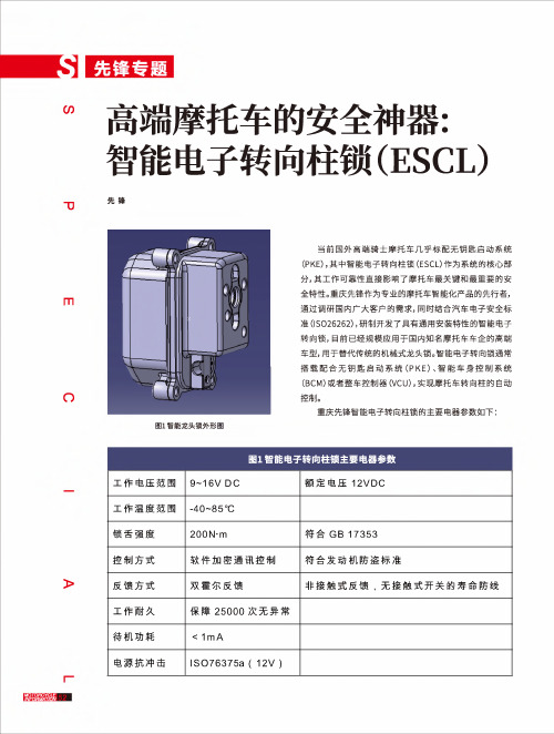
s高端摩托车的安全神器: 智能电子转向柱锁(ESCL)先锋图1智能龙头锁外形图o当前国外高端骑士摩托车几乎标配无钥匙启动系统(PKE),其中智能电子转向柱锁(ESCL)作为系统的核心部分,其工作可靠性直接影响了摩托车最关键和最重要的安 全特性。
重庆先锋作为专业的摩托车智能化产品的先行者,通过调研国内广大客户的需求,同时结合汽车电子安全标 准(ISO26262),研制开发了具有通用安装特性的智能电子转向锁,目前已经规模应用于国内知名摩托车车企的高端车型,用于替代传统的机械式龙头锁。
智能电子转向锁通常 搭载配合无钥匙启动系统(PKE)、智能车身控制系统(BCM)或者整车控制器(VCU),实现摩托车转向柱的自动控制。
重庆先锋智能电子转向柱锁的主要电器参数如下:A工作电压范围9~16V DC 额定电压12VDC工作温度范围-40~85°C锁舌强度200N-m符合 GB 17353控制方式软件加密通讯控制符合发动机防盗标准反馈方式双霍尔反馈非接触式反馈,无接触式开关的寿命防线工作耐久保障25000次无异常待机功耗v 1mA电源抗冲击ISO76375a ( 12V)传统机械式车头锁有两个作用:一是用于防盗,锁舌伸出时可以锁止车头不能旋转;二是用于整车电源的接通(IGN On),让车载各类电器通电工作。
图2机械车头锁我们在进行智能电子转向锁替代方案时,从原理功能上和安全性两个方面考虑,来模拟人为操作的过程。
图3机械车头锁的控制逻辑钮,无钥匙启动控制器(PKE)通过与智能电子转向锁进行加密通讯,控制车头解锁和电源控制。
虽然这种方式极大地提升用户体验,但问题是电子产品的故障率比机械结构高,并且功能方面包含着安全性风险。
一旦电子产品出现故障,那么就有失控的风险。
图4电子车头锁的控制逻辑在智能电子转向锁的安全设计理念上,我们认为规避所有失效风险是不太现实的,但可以保证电子转向锁在失效模式下不会违规动作,那么摩托车在骑行过程中就没有安全风险。
英克瑞梯控ic密钥-概述说明以及解释

英克瑞梯控ic密钥-概述说明以及解释1.引言1.1 概述概述部分的内容可以如下所示:英克瑞梯控ic密钥是一种用于梯控系统的安全认证技术。
梯控系统在现代社会中得到广泛应用,它通过限制进入特定区域的人员来保障安全。
而ic密钥作为梯控系统的核心部分,起到了关键的作用。
在传统的梯控系统中,人们常常使用传统的钥匙或密码进行身份验证,然而这种方式存在诸多弊端。
钥匙易丢失、被复制,而密码则容易被破解或泄露,从而给安全带来了极大的隐患。
为了解决这些问题,英克瑞梯控ic密钥应运而生。
英克瑞梯控ic密钥采用了先进的射频识别(RFID)技术,将传统的钥匙或密码替代为小巧的ic卡或ic标签。
通过将个人身份信息和访问权限存储在ic卡中,并与梯控系统进行交互,英克瑞梯控ic密钥能够快速、准确地验证用户身份,并实现对特定区域的准入控制。
除了提供更高的安全性外,英克瑞梯控ic密钥还具有多种优势。
首先,使用ic卡或ic标签进行身份验证更加方便快捷,用户只需将ic卡或ic标签靠近读卡器即可完成身份验证,避免了记忆繁琐的密码或携带沉重的钥匙。
其次,ic卡和ic标签可以被复制的概率相对较低,确保了系统的安全性。
此外,英克瑞梯控ic密钥还具备扩展性强、易于管理及低成本等特点。
总之,英克瑞梯控ic密钥作为一种先进的安全认证技术,为梯控系统提供了更高的安全性、便捷性和经济性。
在接下来的文章内容中,我们将详细介绍英克瑞梯控ic密钥的应用领域、特点和优势,并展望其未来的发展前景。
1.2 文章结构文章结构部分的内容应该描述整篇文章的布局和组织方式。
在这种情况下,可以写以下内容:在本文中,将从以下几个方面来探讨英克瑞梯控ic密钥的相关内容。
首先,引言部分将对这个主题进行概述,并介绍文章的结构和目的。
接下来,正文部分将探讨英克瑞梯控ic密钥的定义和功能,以及它在不同应用领域的具体应用案例。
然后,将详细介绍英克瑞梯控ic密钥的特点和优势,并分析其与传统密钥系统的区别。
- 1、下载文档前请自行甄别文档内容的完整性,平台不提供额外的编辑、内容补充、找答案等附加服务。
- 2、"仅部分预览"的文档,不可在线预览部分如存在完整性等问题,可反馈申请退款(可完整预览的文档不适用该条件!)。
- 3、如文档侵犯您的权益,请联系客服反馈,我们会尽快为您处理(人工客服工作时间:9:00-18:30)。
The EKS is widespread amongst automotive manufacturers and suppliers. In addition it is used in applications in the process-oriented industry, e.g. in the production of food, pharmaceutical or chemical products. Protecting access to critical processes is a central topic in the typical applications.
■ A commercially available Windows PC ■ An EKS Electronic-Key adapter with USB interface ■ The Electronic-Key Manager EKM Light software
■ The Electronic-Key-System EKS
is already part of many applications involving electronic access management on PCs and control systems. EKS basically comprises two components: the Electronic-Key with RFID transponder and the Electronic-Key adapter. The Electronic-Key locks into the key adapter and is held there during operation of the installation. Due to the contactless transfer of data, it was possible to design the ElectronicKey adapter from the access side with the high degree of protection IP 67. Thanks to its robust design, the EKS is appreciated as one of the few truly industry-compatible systems.
The Electronic-Key adapter and Electronic-Key are separately parameterized, with values which have to match. Parameter assignment to the Electronic-Key adapter is performed very simply through DIP switches.
■ Electronic access control ■ Simple connection ■ Simple communication, 4-bit output ■ Very flexible use ■ IP 67
With EKS Light, EUCHNER is now opening up the use of EKS technology for small and decentralized applications as well. As previously with EKS, the Light version also permits controlled access to individual machines, entire installations or other facilities. The only difference is that with EKS Light, the device directly identifies a user by his Electronic-Key. A control system is not necessary for this check. If authorized user was detected, an access level is output with which the user receives a certain authorization. The derivation of access rights onto machine functions is carried out through the programming of the control by the system integrator.
EKS Light
More than safety.
Electronic access control
Electronic access control SimSpimlepleccoonnnencetiocntion
VeVreryy fflelexibxliebulsee use SimplSe ciommpmuleniccatoiomn munication
■ Access the easy way...
The existing EKS family is being expanded by a new series in the form of EKS Light, which can be identified by the black front cover.
An EKS operating state, an access level, an access code, a checksum (CRC) and a serial number are stored on the Electronic-Key. When a key is inserted, the data range relevant for the respective operating state is automatically read from the key into the device, temporarily stored there and evaluated. If an authorized user is recognized via a valid Electronic-Key, the outputs on the Electronic-Key adapter are set to High in accordance with the stored access level values. All outputs are reset to Low when the Electronic-Key is withdrawn.
■ Operating state 0 Access is granted when the access codes on the Electronic-Key and DIP switch are an exact match. 1024 codes are possible in this operating state.
■ Operating state 1 Access is granted when there is a match on any bit position of the access codes on Electronic-Key and DIP switch.
How are parameters assigned to Electronic-Keys? Parameter assignment for the Electronic-Keys is performed exclusively via a programming station on the PC. At least the following items are required for this purpose:
The operating state determines the function of the system, which comprises the Electronic-Key adapter and Electronic-Key. The operating state defines the scheme according to which automatic Electronic-Key recognition functions and how an access level is issued.
And this is how it works The EKS Light Electronic-Key adapter is a read-only system with integrated evaluation electronics and interface.
After the key is inserted, the key's data are evaluated within the device as the first step, which permits automatic user recognition without the aid of the control system.
4-Bit parallel interface for output of the access level