VI-201CU中文资料
AQV201中文资料
Input
Item
LED forward current LED reverse voltage Peak forward current Power dissipation Load voltage (peak AC)
Output
Continuous load current
Peak load current
6.4±0.05 .252±.002
3.6±0.2 .142±.008
mm inch
1
61
6
2
52
5
3
43
4
(AQV10 series)
(AQV20 series)
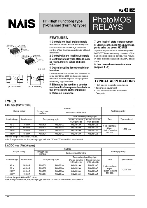
FEATURES
1. Controls low-level analog signals PhotoMOS relays feature extremely low closed-circuit offset voltage to enable control of low-level analog signals without distortion.
TYPICAL APPLICATIONS
• High-speed inspection machines • Telephone equipment • Data communication equipment • Computer
TYPES
1. DC type (AQV10 types)
Output rating*
Turn off time*
Typical Maximum
Toff
characteristics I/O capacitance
Typical Ciso
Maximum
062冒险岛中英文NPC对照表
10000 - Pi o皮奥1001000 - S ilver赛尔文1001001- Na tash a娜塔莎1001100-Mi na米娜1002000- Phi l比尔1002001 - T eo特奥1002002-Pa son佩森1002003 - Mr. G ol ds tein智慧爷爷1002004- VI PCa b明珠港星级出租车1002005- M r.K im金先生1002006 - Ch ef吉夫1002100 -Jane简1002101-O laf坤1010100- Rin a丽娜1011000 - K arl卡尔1011001-S am山姆1011100- Lun a卢娜1012000 - R egula r Cab射手村中巴1012001 - Dr.Squin t差不多医生1012002- Vic ious比休斯1012003- Ch ief S tan长老斯坦1012004- Do ofus科尔1012005-Cloy科洛伊1012006 -Tra in er Bar tos巴特斯1012007 -Tr ai nerFrod巴罗德1012008 -C as ey凯茜1012009- Mr. Le e李先生1012100 - At henaPie rc e赫丽娜1012101 -Maya玛亚1012102- Pia皮亚1012103 -Na ta lie娜塔丽1012104 -B rit ta ny伯丽特1012105 - Ms.Tan沃美妮1012106- Mrs. Min g M in g明明女士1012107 - Utah尤塔1012108- Ca mila卡米拉1012109- Jay亚华1012110 -A nne桉1012111 -Bruce布鲁斯1012112- To ry达尔利1012113- T om my达尔米1012114 - Grow lie兴儿1020000 - Blac kbull酋长1021000- Ri ver利伯1021001-H arry慧丽1021100 -A rtu ro格里高利1022000 -Dance s w it hBalr og武术教练1022001 -Re gu larCab勇士部落中巴1022002-M anji麦吉1022003 -M r.Th un der辛德1022004 - Mr. S mi th斯密斯1022005 - Mr.Wan g王先生1022006 - Wi nston芳博士1022007 - A yan伊安1022008-B urnt Swo rd灰渣里的剑1022100- Sop hia索非亚1022101 -Ro on ey露妮1022102- The Ex ca va torBoar d遗迹发掘队布告栏1031000 -F lora theFairy妖精佛罗拉1031001- Ser abit heFa ir y妖精舍拉比1031100 -Lent he Fai ry妖精莲1032000 -Re gu larCab魔法林中巴1032001-Gr ende l th e Rea llyO ld汉斯1032002 -Franc ois易德1032003 -Shan e赛恩1032004 -L ou is路易斯1032005 - VI P C ab魔法林星级出租车1032006 -M r.Pa rk朴先生1032007- Joe l售票员1032008 -Cherr y检票员1032009 -P urin船员普林1032100-A rwen the Fair y妖精艾温1032101- Row en th e Fai ry妖精罗雯1032102 - Ma r the Fa ir y妖精玛丽1032103- ElMot h阿尔莫斯1032104 - B etty巴缇1032105- Est elle胡小姐1032106- Win g th e Fai ry妖精维英1040000- Luk e鲁克1040001 -M ik e麦克1040002 - Fanz y潘喜1043000 - a pile off low er s花簇1043001 - a pile ofh er bs草药丛1051000 - Cu tth ro at Man ny曼斯塔1051001- D onH wang玛帕1051002 -D r.Fa ym us铭仁1052000- Ale x阿勒斯1052001 -DarkLord达克鲁1052002- JM From thaStr ee tz后街吉姆1052003- Chr is克利思1052004 - Denm a the Ow ne r黛玛院长1052005 - Dr.Fee bl e差不多医生1052006- Jak e冬青1052007 - T he Ti cketGat e检票口1052008 - Tr easur e C he st宝箱1052009 -Treas ureC he st宝箱1052010- Tre asu reC hest宝箱1052011 -E xit出口1052012 - Mong from Ko ng马龙1052013 - Co mpute r电脑1052014 - V endin g Mac hin e自动售货机1052015 -Billy比利1052016- Re gular Cab废都中巴1052017 - M r. Ho ng洪先生1052100 -DonGiova nni钱老板1052101- And re安德里亚1052102-Shum i休咪1052103 -Nel la内拉1052104 - Tu lcus图里卡斯1052105 - J ane D oe不认识的女人1052106 - I carus伊卡路斯1061000 -C hris hrama克利斯拉玛1061001 -24 H r 禁止词语leS tor e24小时排档1061002- Mr. Sw ea tb otto m豪素夫1061003- Mr.We tbot tom泰素夫1061004 -Ro nn ie洛尼1061005- Sab itr am a萨比特拉玛1061006- Mys ter io us Sta tue奇怪的石像1061007-Cr umbl ingStatu e坍塌的石像1061008- Mr. Oh吴先生1061009-Door ofDimen sion异界之门1061010 - S parkl ingC rys ta l闪耀的水晶1061011- The Re me mb erer记忆者1061012 -Ins ig ni fica nt B eing无意义存在者1061013 -Gwin葛温1061100 -Ho te l Re cept ionis t宾馆服务员1063000- a p ile o f pin k f lo we rs粉红色花簇1063001 -a p il eofb lueflowe rs蓝花簇1063002- a p ile o f whi tefl ow ers白花簇1063003 -W ant ed: G.Mush room绿蘑菇通缉牌1063004 -Want ed :Curse Ey e风独眼兽通缉牌1063005- Wan ted:E vilEye火独眼兽通缉牌1063006-Want ed : Cold Eye冰独眼兽通缉牌1063007- Wan ted: Z.M us hroo m僵尸蘑菇通缉牌1063008-Wa nted : H. Mus hroom刺蘑菇通缉牌1063009- Wan ted: Jr.Bo ogie幼魔精灵通缉牌1063010 -W an ted: Dr ake青龙通缉牌1072000- Wa rrio r Job Inst ruc to r战士转职教官1072001 - Ma gic ia nJobInst ructo r魔法师转职教官1072002 - B owman JobIns tr uc tor弓箭手转职教官1072003 -Th ie f Jo b In struc tor飞侠转职教官1072004 -Warri or Jo b I ns tr ucto r战士转职教官1072005 -M ag icia n Jo b Ins truct or魔法师转职教官1072006 -Bowma n J obI nstr ucto r弓箭手转职教官1072007- Th iefJob I nstru cto r飞侠转职教官1081000 - Vale n拜伦1081001 - P ison派申1081100-Riel丽尔1081101 -R oel露尔1081102 - Rael拉尔11000-S id赛德11100 -Lucy露茜12000 -L ucas路卡斯12100- M ai麦加12101 - Rain瑞恩2000-Ro ger罗杰20000 - John约翰20001 -Bari白瑞德20002- B ig gs比格斯2001 - Se n珊2001000- Cli ff克里夫2001001- B ra nc h Sn owma n树枝雪人2001002-M etal Buc ket S nowma n罐头雪人2001003 - Stra w Hat Sn ow ma n草帽雪人2001004 - Sc arfS no wman围巾雪人2001005- Ru pe rt珞巴特2002 - Pe ter彼特2002000 -Rupi鲁皮2002001 -R ud i 鲁迪2002002- Tor r 头羊2003- Rob in罗宾2004 -To dd透德2005- Sam叁20100-Yo ona尤娜2010000 - St affS er gean t Ch arlie查里中士2010001 -M inothe O wner米努2010002- Fra nz th e Own er弗兰克2010003 - Neve奈巴2010004- Cor pora l Wil son瑞撒上等兵2010005 - S huri贵英2010006-Trin a小刘2010007 -Her ac le哈拉克2010008 - Lea蕾雅2012000- Aga tha桑艺2012001-R ini田菲2012002 - Er in阿霖2012003 -NeritheF air y妖精娜丽2012004 -NuritheF ai ry妖精诺丽2012005 -Ede lth e Fa iry妖精易多2012006-Pl atfo rm U sher艺斯2012007-Rinz the Assi stant利纳斯2012008 - R omi罗米2012009-R izatheAssis tant利嘉2012010- Elm a the Hous eke ep er保姆珥玛2012011 - Kr ielt he Fai ry妖精珂丽尔2012012-Li sa莉萨2012013- Sun ny斯娜2012014 -Orbis Magi c S po t天空之城魔法石2012015 -E l N at hMagi c Sp ot冰封雪域魔法石2012016 -A ilee n莎米2012017 -H ug hestheFuse秀兹2012018-Eric sson艾利逊2012019 -M op pie波达2012020 - Al fon seG reen阿尔冯丝小绿2012021 -Ra mi ni娜米2012022- Pel ace帕拉斯2012023- Map le Le afMa rb le枫叶霜2012024 - Eg net温莉2012025 - Gera s帮佣易克2013000 -Wonk y the Fair y雅典娜女神2013001- Cha mberl ainE ak伯坚2013002 -Miner vath eGodd ess斯考特2020000 -Vo ge n伯坚2020001 - Scot t斯考特2020002 -Gordo n高登2020003- Ma ster Serg eantFox珀斯上尉2020004 - Mr. Moh amm ed武先生2020005 - A lcast er阿尔卡斯特2020006 - Ja de杰德2020007 -S cadu r斯卡德2020008-Ty lus泰勒斯2020009 -R obe ir a鲁碧2020010 - R ene蕾妮2020011 -Arec艾瑞克2022000 -R um i卢米2022001 - Hana哈娜2022002- Ba run巴兰2022003-S hamm os邪摩斯2022004- T yl us泰勒斯2030000 - Jeff杰夫2030001- Se rgean t Bra vo巴伯下士2030002- Cor poral Ea sy伊吉上等兵2030003 - Rock Co ve re d in Sno w雪岩2030004 -S ma llT omb小墓地2030005 -St at ue雕像2030006- Hol y S to ne神圣的石头2030007 - Pi eceo fStat ue石像的碎片2030008 -A do bis阿杜比斯2030009 -Gli bb er格里巴2030010 - Amon阿们2030011- Al i阿尔利2030012-H uckl e何克2030013 -Ado bi s阿杜比斯2030014 - Anci entI cy Sto ne上古冰2032000- ????助手2032001 - S pirun a斯皮罗纳2032002 - Aura奥拉2032003- Lir a利拉2032004 -Sus pi ci ousLava熔岩2040000 -Me l美尔2040001 - D elvt heTo ySold ier玩具兵得利巴2040002-O lson the ToySoldi er玩具兵哦尔萨恩2040003 -Assis tan tCh eng助教尚2040004 -Rol y-Po ly1玩具工人12040005- R ol y-Poly 2玩具工人22040006 -R ol y-Po ly 3玩具工人32040007-R oly-Poly 4玩具工人42040008- Rol y-Po ly 5玩具工人52040009 -R oly-Poly6玩具工人62040010- Rol y-Pol y 7玩具工人72040011 - R oly-P oly8玩具工人82040012 - Roly-Poly 9玩具工人92040013 - Ro ly-Po ly10玩具工人102040014- Chi co奇可2040015 -Manag er Ka rl厂长卡胡2040016- Pi派2040017-G reen Mes orang er冒险勇者绿虎2040018 -Black Meso ran ge r冒险勇者熊猫2040019 -E ver to n埃巴2040020 - S arah吉乐肯2040021- Ta ra珮2040022 -R yd ole莱德里2040023 -L ostS ol dier迷路的士兵2040024- F ir st Eos Roc k第一个玩具塔石2040025- Se cond EosRock第二个玩具塔石2040026- Thi rd Eo s R oc k第三个玩具塔石2040027 -F our thE osR ock第四个玩具塔石2040028-Mark the ToySoldi er玩具兵马可2040029 - Gr andpa Cl oc k挂钟2040030 - W isp威舍2040031 -Docu mentRoll文件包2040032- We aver威巴2040033-Neru奈勒2040034 -R edSi gn警示2040035 -Artur o阿里特2040036 -Red B alloo n红色气球2040037 - Oran ge Ba llo on橙色气球2040038 -Yello w B al lo on黄色气球2040039 -L imeB al loon绿黄气球2040040- Gr ee nBall oon绿色气球2040041 -A qu a Ba lloo n海蓝气球2040042-S ky-B lueBallo on天蓝气球2040043- Blu e Bal loon蓝色气球2040044 - V iolet Ball oon紫色气球2040045 - Pi nk Ba llo on粉红气球2040046 -Rober t H ol ly哈尔里2040047 - Sgt. An de rs on士兵爱那得斯2040048- N ar a爱丽2040049 - G umbal l M ac hi ne糖果机器2040050 -E ure kth e Al chem ist流浪炼金术士2040051 -T oly小泰2040052- W izt heL ibra rian威兹2041000-Tian田安2041001 -R ose y俄林2041002- Hid和答2041003- Mir u米鲁2041004 -Mar ce l马勒萨里2041005 - Nemi乃米2041006- Mi sky米舍凯2041007-Miyu米约2041008 -S epp y舍琵2041009- Min i咪咪2041010- El lie爱丽2041011- Y el lo w Me sora nger冒险勇者黄雄2041012- Pin k Mes orang er冒险勇者粉狼2041013 -Gina吉纳2041014- Pat ricia帕特里沙2041015 -K orin克林2041016 -Ve ga弥勒吉尔2041017- Ace ofH ea rts库克斯2041018 -H anst he Ass embl er工程师汉斯2041019- Ro ckythe R epair man修理工镂刻2041020 -Mact heMe ch anic机械工麦戈2041021 -Mr.Bouf fon闵先生2041022 -Ti gu n th e Ad visor士官提甘2041023 -Flo炮娄2041024- T om bs tone造型物2041025 -Mac hi ne App arat us机械装置2041026-Ghos thun ter B ob幽灵猎人巴柏2041027 -Mason theCol le ct or搜集狂麦森2041028 -Unk no wn Thi ef飞侠转职教官2042000-Sp iege lman n休彼德蔓2042001-S pieg elma nn休彼德蔓2042002-Spie gelm ann休彼德蔓2042003- Ass ista nt Re d红队助手2042004 -Assi stant Blue蓝队助手2050000 -Dr. S an大山2050001 -D r. K im金博士2050002-A lien Gra y外星人哥雷2050003- Spa cen斯派斯尼2050004 -K ub o th e St orage man具宝2050005 -Chur y阿哲2050006 -H oo ny阿海2050007- Gun ny阿亮2050008 -Gener al Ma est ro马斯特将军2050009- Jr. Of fi ce r Me din参谋美得恩2050010-R icetheMedic卫生员莱斯2050011- Kev in th e Sol die r士兵克斌2050012 -Agent Ma rc o工作员M2050013- Por ter波特2050014 - Mete orite 1陨石12050015 -Meteo rit e2陨石22050016 -Meteo rit e3陨石32050017 -Meteo rit e4陨石42050018 -Meteo rit e5陨石52050019 -Meteo rit e6陨石62050020 -Drops hip载运船2051000- Dr. Pepp er珮珀2051001 -Kay卡伊2060000-N anuk e纳努科2060001- Ro bi ns on鲁宾逊2060002 - Ta e G on g太公2060003 - M elias艾里亚斯2060004 -Oanne s安纳斯2060005 -K enta坎特2060006 -Mu se妙斯2060007 -Calyp so卡利2060008 -Gerra rd杰拉德2060009 -Dolp hin海豚2060100-C arta卡勒塔2060101 -Tae ngt heE xplo rer探险队长坦克2060102 -Door to t he Wa rpe dDi mens ion次元空间入口2070000-M r.N oh鲁先生2070001- B un g's Ma ma芭德阿姨2070002 -Mo ki墨铁2070003 -Dori石铁2071000- Chu mji朴大爷2071001-Hong bu兴夫2071002- No lb u乐夫2071003 - C hilN am七南2071004 -KongJi小荳2071005 -C hilSung七诚2071006-Swal low燕子2071007- G ra nd maY eon莲婆婆2071008 -Ha en im小日2071009- Mr. Sh im沈师铭2071010 - G od of Mo un ta ins山神2071011 - Tr eeCu tt er樵夫2072000- Chi l S un g's Ri ce S tacks七诚家的稻穗2072001- Chi l Nam's Ri ceSt ac ks七南家的稻穗2073000- Pa rkC humJi2080000 -M os摩斯2080001 -Sly史莱2080002-M ax马克斯2080003 - No rma n诺蔓2080004- Moo die马蒂2080005 -Kosc u寇斯库2080006-Do lphi n海豚出租车2081000 -Ch ie f Ta tamo村长塔塔曼2081001-K umo库摩2081002 - It o依托2081003 - Y aku亚可2081004-P am潘姆2081005- Ker obe n可罗宾2081006 - Mo ira摩伊拉2081007- Rau l the Knig ht骑士拉乌尔2081008 - Ni ne Sp iri t'sBaby Dra gon九灵龙宝宝2081009- Mo ose姆斯2081010- M oo se姆斯2081100 -Harmo nia哈尔模尼亚2081200 - G ritto格里特2081300 - L egor列高罗2081400- Hel lin哈林2082000- M ue纽曼2082001 - To mmie塔咪2082002- Har ry哈利2083000-En cryp tedSlate oft heSq ua d敢死队的暗号石板2083001- H or nt ail's Sc hedul e暗黑龙王的里程碑2083002 -Cryst al of Ro ot s树根水晶2083003 - Stum p a tth e Ro om o f Maz e迷宫碎片2083004 -Mark of t he Sq uad远征队的标识2083005 -Fount aino fLife生命之泉2090000- Mr.Pa n老盼2090001 - Gong Go ng功功2090002 - Bi diwon防防2090003- Da lsuk达淑2090004-Mr.Do陈道人2090005- H ak鹤2090006- Lay a拉丫头2090100 -G rand pa Lu o老爹爹2090101 -L ilis hu丽秀秀2090102-N aran纳兰2090103 -Pat a巴塔2090104- Nom a诺马2091000- No Gon g诺功2091001 -D oGong道功2091002 -T aeSa ng太上2091003 -TaeS oo韩太守2091004 - Mast er Go bli n2092000 -Mr. K u邱老头2092001 -C apta in Hw ang黄船长2093000- MuTan武旦2093001-S o Wo n小防防2093002- La nMi ng兰明2093003- Mr. Go ng宫相公2093004 - D olphi n海豚2094000 - G uon久翁2094001-W u Ya ng无恙2094002- Gu on久翁2100 -Sera莎丽21000-Pa n潘2100000 -Ahmad阿赫马德2100001 -Muham ad莫哈莫德2100002- Zai d寨尔德2100003-Ja smin雅思敏2100004 -Sag aT萨哥特2100005 - S hati夏特2100006- Maz ra玛兹拉2100007-L ila拉尔拉2100008 -V ard八德乐2100009- Ald in阿尔丁2101- Hee na希娜2101000- Si ri n西琳2101001 - J iyoul e智由拉2101002 -Elesk a呃拉斯卡2101003 -Ardi n阿丁2101004 -T gu n提干2101005 - Byro n巴一岚2101006 -Le Pe titP rin ce小王子2101007 - A reda阿烈达2101008- Sc heger azade世赫拉2101009 - A bdull ah VI II阿得拉8世2101010 - Ja no扎诺2101011 -S ejan携詹2101012 -St ra ngeGuy可疑的男子2101013-Ka rcas a卡乐卡萨2102 -N ina妮娜2102000 - Ases son阿世顺2102001- Sly n斯林2102002 -S yr as西拉斯2103 -Maria玛丽亚2103000 - P alace Oasi s宫廷绿洲2103001 - Secr et wa ll秘密之墙2103002- Que en'scab in et王妃的装饰柜2103003 -A ria ntp riva te h ouse1阿里安特民宅12103004- Ar iantpriva teho us e2阿里安特民宅22103005- A ri an t pr ivat e hou se4阿里安特民宅42103006 - Aria nt pr iva teh ouse6阿里安特民宅62103007-Tr easu re B ox宝物箱2103008-M yste riou s voi ce奇妙的声音2103009- Ar iantpriva teho us e1C upbo ard阿里安特民宅1橱柜2103010- Ar iantpriva teho us e2C upbo ard阿里安特民宅2橱柜2103011- Ar iantpriva teho us e4C upbo ard阿里安特民宅4橱柜2103012- Ar iantpriva teho us e6C upbo ard阿里安特民宅6橱柜2110000- Ro sen罗森2110001-J erry哲里2110002 -K yol吉欧2110003 - Rama in拉玛人2110004 -Mere n威尔斯2110005-Ca melTaxi骆驼中巴2111000-Ca rson卡森2111001 -M aed麦麦德2111002- Delang德朗博2111003- Hu manoi d A人造人A2111004 - P hilia琵丽雅2111005- Ki ny琦尼2111006- Pa we n疯老头2111007 -Broke r H an.后街小贩2111008 - Bedi n.贝丁2111009 -Russe llon罗赛伦2111010- Al chede no'sCab in et.卡帕莱特的书页2111011- Wa ll墙2111012- Cab inet书页2111013- Pic tureframe镜框2111014- De sk桌子2111015-Ru ssel lon's Des k罗赛伦的桌子2111016- De Lang's Se cre tbo ok德朗博士秘密书2111017- 1stP ipehand le第一个拐杖2111018- 2nd Pip e han dle第二个拐杖2111019 - 3rd Pi pe ha ndl e第三个拐杖2111020 -1stM agi ca larra y.第一个魔法阵2111021-2n d Ma gica l arr ay第二个魔法阵2111022 - 3rd Ma gical ar ra y第三个魔法阵2111023 - Ma gic ala rray cen ter.魔法阵中央2111024 -S ecre t pas sege秘密通道2112000 - Y ulete犹泰2112001- Yul ete犹泰2112002- Y ul et e犹泰2112003 - Brit tan y朱丽叶2112004 - Br ady罗密欧2112005- Bri ttany朱丽叶2112006- Br ady罗密欧2112007 -In ve stig atio n Res ult.调查结果2112008 - B ritta ny朱丽叶2112009 -Brad y罗密欧2112010-Yu lete犹泰2112011 -Y ule te犹泰2112012 - Yu lete犹泰2112013- Inv estig ation Re su lt.调查结果22000 - Shan ks桑克斯9000000 - Paul珀尔9000001- Jea n江9000002 -P iet ro比特罗9000003 - V ikan贝坎9000004- Vik on贝根9000005-Vi kone贝肯9000006 -V iko on贝昆9000007 - Ch un Ji千吉9000008- Mr. Pic kall权达开9000009- Vi kin贝干9000010-P ietr a比特拉9000011- Ma rt in马丁9000012 -Harry亨利9000013- To ny透尼9000014-Ge anie基尼9000015 -T ami s塔密斯9000017 - Co co可可9000018 -M atil da9000019 -Ro ck, Pa per, Scis sorA dmi n9000020 -Spine l导游妮妮9010000 -Mapl e Adm inist rat or冒险岛运营员9010001- Tia可乐小姐9010002 - Mia9010003-Ri a9010004 - M ia9010005- Dia ne9010006 -S all y北极熊蒲企9010007 -Josh9010008 -P etti te9010009 -Du ey杜宜9010010 -Cassa ndr a卡珊德拉9010011 - O range Mu sh ro om花蘑菇9010012 - St arPi xi e星光精灵9010013 - He ngk i变种侏儒怪9010014 -Arami a阿乐米9020000 -Lakel is拉克里斯9020001- Clo to克鲁特9020002-N ella内拉9030000 -F red ri ck弗兰德里9030100- Scr oog e斯克鲁吉9040000 -Shuan g修安9040001 - N uris努里斯9040002- Sha wn杉峰9040003- Sh ar en III's S oul锡安列三世的灵魂9040004- Hon orabl e Roc k荣耀之石9040005 - Retu rning Ro ck回传之石9040006 -Guard St at ue人象之石9040007- Sha renI II'sW ill锡安列三世的遗书9040008- Gui ld R ank B oard公会排行布告栏9040009- Gat ekeep er城门守门人9040010 - Ti gerS tat ue飞虎石像9040011 -Bulle tinB oa rd留言板9040012 - Kn igh tAr mor骑士铠甲9050000 -Pig mit heS ummo ner9050001 -P ig mit he S ummon er9050002- Pig mi t he Su mmone r9050003- Pig mi th e Sum mon er9050004 - Pigm i the Su mm on er9050005 -Pigmi th eSu mmon er9050006 -P igm ith e Su mmon er9050007 -Pi gm i th e Su mmone r9050008-Pigm i an d Etr an9050009- Etr an's Info rmati onBo ar d9060000 - K enta肯塔9060001- Ken ta9100000 -Ke rn ingCity Mane kinek o9100001- Hen esysManek ine ko9100002 - Elli niaM ane ki ne ko9100003 -Perio n M an ek inek o9100004 - Sl eep yw oo d Ma neki neko9100100-Ga chap on9100101 -G ach ap on9100102 - Ga chapo n9100103- Gac hapon9100104-G acha pon9100105 -Gac ha po n9100106 - G achap on9100107- Ga chapo n9100108-Gach apon9100109- Ga ch ap on9100110 -Gacha pon119100111 - Gach apon129100200- Pac hinko 19100201- Pac hink o 29100202 -P ac hink o 39100203 -Pac hi nk o 49100204 - Pach ink o59100205- Pac hinko 69101000- No Stri ng9101001- Pet er9101002 -T odd9101003 - P eter9102000-Sc on9102001 -Garno x9103000- Pie tri9103001 -R ol ly9103002 -Rolly9103003 -Roll y9110000- P er ry9110001 - Ra imut heWa rr ior9110002 - Kino Ko no ko9110003 - Ja nken9110004 -T aru9110005 -Bro nz e9110006- Jin Jia9110007 -R obo9110008 -Per ry9110009 - Elli niaG a-c ha-p on快乐百宝箱9110010 -Hen es ys Ga-cha-pon快乐百宝箱9110011- Pe rion Ga-c ha-po n快乐百宝箱9110012- Ker ningCit yGa-cha-pon快乐百宝箱9110013-S leep ywoo d Ga-cha-p on快乐百宝箱9110014 - El Nath Ga-c ha-pon快乐百宝箱9110015- M us hr oomStat ue快乐百宝箱9110016- NoStri ng.高级快乐百宝箱9110100 -Char ity B ox9120000- Shi nta9120001 -Han ak o9120002- Dor an9120003- Hik ari9120004 -Mom oy o9120005- Umi9120006-S kai9120007 - Fura no9120008- Ts uri9120009 -Y us e9120010 - F aito9120011 -S akur a9120012- F ra id y Ca t9120013 - Bo ssKi tt y9120014 - P opo9120015- Ko npei9120016- Ma ri wa ka9120017 -PoniCha i9120018 -Grako9120019-M omoy o9120020 - Mi nst ei n9120021- Cla mshel l9120022- Man stein9120023-Y okoY oko9120024 -Uer ib a9120100- Tep ei9120101- Mid ori9120102 -Hik ek ur o9120103 - S aeko9120104 -N aoko9120200- Ko np ei9120201 - Ko npei9120202 -K onpe i9120203- K on pe i9200000 - C ody通常被修改为BO SS传送的NPC 9200001- Ma dBu nny目中无人兔兔9200100- D r.L enu9200101 - Dr.Rho me s9200102- Dr. Bosc h9201000- Moo ny9201001 -Na na(H)射手村n ana9201002 -H ig h Pr iest John9201003-M oma nd D ad9201004 -Am es the Wis e9201005- A ss is tant Nic ole9201006 -A ss ista nt D ebbie9201007-A ssis tant Nanc y9201008-Assi stan t Bon nie9201009- As sist ant J ackie9201010 -Assi stant Trav is9201011- Pe lvisBebop9201012 -Wayn e9201013- V ic to ria9201014 - Pila Pr es en t9201015 - J ulius St yl em an9201016 -Salon Se am us9201017 - Dr.Robe rts9201018 - D r. 902129201019- In tern Shak ihand s9201020- Viv ian B outiq ue9201021- Ro bin T he Hu ntr es s9201022- Tho masS wif t9201023 -Nana(K) 废气都市的娜娜,通常被修改为商店9201024- Na na(E)9201025 - N ana(O) 天空之城nana9201026- Nan a(L)9201027 -Nana(P) 勇士NA NA9201028 - Mala dy9201029- Gra ndma Bens on9201030- Map le C laws圣诞猫咪9201031 -H anna h9201032- M r.K itK at 幸福村厨师9201033-Si mon9201034 - Ben9201035 -J acob9201036- An ge li que9201037 - Gary an dSh atim a9201038 - Ri cha rdt heS ailo r9201039- C la ud ia9201040 -Mr.S pot9201041 - B ullse ye9201042- Mr. San dman9201043-Am ost he S trong9201044-A mostheStron g9201045-Amos the Stro ng9201046- Amo s th e Str ong9201047- Th e Gl immer Man9201048 -A mosthe S trong9201049 -Ames theWise9201050 -I ceby rd Sl imm9201051- Jo hn B arric ade9201052- Pr ofes sor F oxwit9201053 -Jack Masq ue9201054- Lit a La wless9201055-E lpam Gor lab9201056 -N LC Tax i9201057 - Be ll9201058- De lphi9201059-Ky le9201060 -Miki9201061 -B omac k9201062- J.J.9201063- Ari9201064-M ani9201065 - Mira nda9201066 - N LC Ma pleT V9201067- Cla w Mac hine9201068 -N LC t icket gate9201069 -V. I sage9201070-Ne rbit9201071- Sun sto neG rave9201072- Moo nst on eGrav e9201073 - To mbs to ne9201074 - Bo b9201075-Agen t Fa lcon9201076-Lu dmil la9201077 -J ona sPr ende rgas t9201078- S op hi lia9201079 - OldManT om9201080 - Ed munds9201081 -Rob9201082 -Spi nd le9201083 - Th e Gli mme rMa n9201084 - T ombst one9201085 - N ichol as9201086- And y9201087 - Ka te9201088- Ba rry9201089 -A le x9201090 - J ill9201091- O-Pong o9201092- M r.G rubb er9201093 -L itt leS uzy9220004 - Happ y洒雪小矮人9220005- Roo dolph麋鹿诺古9220006 - Bill巴迪9250023- Aqu ariu m Map le TV9250024 -El N ath M apleTV9250025- Fr ee Ma rketMap leT V 9250026 - L udibr iumM ap leT V 9250042 - He nes ysM aple TV9250043 -Ker ni ng Cit y Ma ple T V 9250044-Elin ia M apleTV9250045- Per ionMaple TV9250046- Or bisMaple TV9250052- Pa perb oy。
CONCEPT 201 C 用户手册说明书

CONCEPT 201 CUSER’S MANUALCONCEPT 201 C TABLE OF CONTENTS MACHINE DESCRIPTION:Manufacturer’s address: (3)Range of application: (3)Maximum capacity of the unit: (3)Principle description: (3)Safety Warnings: (4)PRE INSTALATION:Technical datas : (5)Crate dimension: (5)Floor space requirement: (5)Connections location : (6)Accessories needed for the connections: (6)INSTALLATIONUnpacking: (7)Parts delivered with the machine : (8)Connections: (9)USER'S MANUAL:Initial operation of the machine: (10)Machine configuration: (11)Value modification: (12)Section selection: (13)Plate data memorisation: (14)Process visualisation: (17)Start a Washout cycle: (18)Start an Exposure cycle: (18)Start a Drying cycle: (19)Dryer automatic switch off: (19)Start a Post-Exposure / Light Finishing cycle: (20)Alarms: (21)Edition AA, May 2010This book has part No. 10068538Manufacturer’s address:DEGRAF S.p.A."Il Girasole" - Palazzo Donatello 8/03b20084 Lacchiarella (MI)ItalyRange of application:This unit is a part of a full range dedicated for the treatment of flexographic printing plates. This range includes Exposure, Processor, Dryer and light finisher.The unit is designed for the exposure, the washout, the drying as well as the post exposure and light finishing of solvent washable printing plates.Maximum capacity of the unit:Warning:This unit is designed to work with solvent and has been tested with conventional product. Always ask your dealer before trying to change the type of solvent. This may result in major damages and safety issues. This machine has not been designed as an explosion proof unit.Principle description:•This unit is designed to expose, wash, clean, dry, post expose and light finish printing plates.•The machine is divided in major sectionso Control panel: allow the operator to select the correct parameters to process the plates.o Washout section: designed to provide high quality and even washout of the plates as well as high performance cleaning.o Exposure section : 18 lamps of 60W to ensure even exposureo Dryer section: 4 drawers. 2x 800W heating resistors.o Post exposure /light finishing section: 12 UVA lamps (60W) and 11 UVC lamps(75 W).•The operator interface is made touch screen which ensures a very easy interface.Safety Warnings:Technical datas :Crate dimension:•Please ensure the handling of the cratewill be compatible with the buildingconfiguration: doors dimensions, loadcapacity of the floor …Floor space requirement:•Please ensure there will be sufficient space around the machine for safe use as well as easy access for maintenance. 1 meter free space is needed in front of the machine to give an easy access. On the sides and the back of the unit 500 mm are requested to allow the access.Connections location : • All the connection points are located on the back of the unit.Accessories needed for the connections:Upon receipt of your machine please check with the carrier the status of the crate. Notify him of any damage you see on the crate.Before starting to unpack the unit, make sure you have all required tools ready to hand. Unpacking:Warning: For safety reasons, please wear appropriate protective clothing (gloves, glasses, and safety shoes) while unpacking.•Start by removing the top section of the crate.•Remove the sides one by one.•The machine is now resting on the base of the crate.•Remove all blocking pieces of wood.•Use the appropriate forklift to lift the unit and get it to its installation location. Take care that the forks are long enough to lift the machine without causing damage.•Ensure there is sufficient space around the machine (see Pre-installation section).•Remove all protection from the unit (do not use sharp tools to prevent damages).•No special anchorage is needed for this unit. The unit will rest only on its feet.•Align the machine precisely by means of a water gauge. The alignment is made by using the adjustable feet.Parts delivered with the machine :Verify that all parts are with the machine.Connections:All the needed connections have to be made in accordance with the rules of the installation country.Electrical connection :•Connection such as electrical power supply has to be made by certified people.•It is recommended to use a ground fault circuit breaker as well as a lockout type power switch for the electrical connection.•Before switching on the machine, ensure that the voltage measured on the main switch of the machine match the identification plate fixed on the back of the unit. Exhaust blower connection:•Connect all the exhaust, except the exposure exhaust which may blow into the room, to the appropriate location (directly to the outside or to the building exhaust installation). Ensure the airflow is correct.Compressed air connection:•Connect the compressed air line to the unit.Solvent connection:•Connect the solvent lines to the correct points.•Connect the solvent level sensors (high level used solvent and low level fresh solvent) in the correct plugs.Filling the heater/cooler tank:•Remove the panel located on the left side of the unit.•Remove the cover of the heater/cooler tank.•Prepare 4 litters of a solution based on 70% of de-mineralized water (or distilled water), 30% of ethylene glycol and some drops of algaecide (anti-foam action).•Fill the tank to the maximum.•After running the unit for a couple of minutes, it may be needed to check again the level of the heater/cooler tank and to add solution to reach the correct level.Note: This operation has to be made with the machine switched OFF.Initial operation of the machine:Before switching the machine on make sure that the working area around the machine is clean and free for easy movement.Check if there are any leaks of solvent as well as all the needed supplies:✓Electrical power supply: cable connected and not damaged.✓Compressed air: filter clean and pressure correct.✓Exhaust: hose connected and not damaged.•You are now ready to switch the machine on.•the machine (right-hand side).•Verify, that all emergency stop buttons are released. If not, releasethem by turning them clockwise.•Switch the machine on by pressing the ON/OFF button which islocated beneath the control panel of the machine.•displayed on the touch screen:The machine has been stopped with at least1 plate in process in the processor section.Keep pressing “RESET UNIT” for a few seconds toreset all the on going cycle.Keep pressing “RESTART UNIT” for a fewseconds to restart the processor at exactly thesame status of the power switch OFF. This allowsto continue the process of a plate remaining insidethe processor.NOTE: All the other process carried on at the switch OFF of the unit will be reseted in both case. It is only possible to restart the processor cycle.The machine is ready to be used.Machine configuration:For access to the machine set -up, press the designated key.The machine configuration screen allows you to set the machine:The machine configuration screen allows you to modify:in theManual: UVA and UVC can be started separately or all together.Automatic: UVA and UVC will be made one after the other in a sequence depending ofthe first one started.Value modification:•To change a value (numeric or alpha numeric) directly press the desired value and the corresponding keypad will appear.Alpha numeric keypad: Numeric keypad:•Enter the new value and then confirm by pressing .•To close the keypad, press.•If the entered value is out of range of the data it will return automatically to the minimum or maximum range limit. Note: these range limits are different for the same data depending on the setup of the machine.The data are automatically stored in memory as soon as the key is pressed.Section selection:It is possible to change from one section to another one simply by pressing on the section desired on the right of the screen. The activated section is shown in black.Washout section selected. Exposure section selected.Ligth finisher section selected. Dryer section selected.Plate data memorisation:20 memory channels are available to store the plate data.To switch from one channel to another simply press or . The memorised data are then displayed. It is possible to memorise the plate parameters for the Processor section, the exposure section as well as the Light finisher section. The drying time of the dryer section are memorised but not linked to any memorised plate channel.Exposure section:Press this zone to enter the plate type with thealpha numeric keypad.Note: The plate name is the same for all sectionsfor the same memorisation channel.Press on this zone to enter the back exposuretime with the numeric keypad.Press on this zone to enter the main exposuretime with the numeric keypad.Processor section:Press this zone to enter the plate type with thealpha numeric keypad.Note: The plate name is the same for all sectionsfor the same memorisation channel.Press this zone to enter the washout time with thenumeric keypad.Press this zone to enter the relief expected on theplate (used only for the replenishment calculationwhen the solid content measurement device is notactivated).Press this zone to enter the plate size (in mm orinches depending on the machine configuration).The selection is made by step of 25% of themaximum size. Every press on the touchincrements the plate size from 25 to 50 to 75 to100% and then back to 25 (used only for thereplenishment calculation when the solid contentmeasurement device is not activated).Dryer section:Press on the desired time to enter the drying timeof the corresponding dryer drawer.Light Finisher:Press on this zone to enter the Post exposure time(UVA lamps).Press on this zone to enter the Light Finishingtime (UVC lamps).Process visualisation:•During a cycle, it is possible to see whichfunction is On or OFF in the machine. Simplypress on the dedicated touch to access to thevisualisation screens.•All functions running are coloured in black.•First select the required program by using thekeys or .•Verify, that all parameters are correct.•Open the entrance cover.•Fix the plate on the transport table and ensurethe plate is well fixed. It is not possible to havethe plate well fixed if the sticking material is stillwet.•Close the entrance cover.•To start the cycle, press .Note: During the Washout process it is possible to seethe remaining time on the right part of the screen. Note: It is required to wait between two plates the sticky material is well dry to ensure a good fixation of the plate.WARNING: In case the sticky plate holder is not completely covered with the plate(s)to process, the non covered area must be protected with the cover sheet of flexo plate (for example) to prevent long contact between the sticky material and the solvent. Not doing this may result in very short life time of the sticky material.Start an Exposure cycle:•keys or .•Verify that all parameters are correct.•Open the Exposure drawer.••for digital plates).•exposure cycle has been started.•Close the drawer.•To start the cycle, press“START MAIN”.Note: During an Exposure processit is possible to see the remainingtime on the right part of thescreen.•Be sure the dryer is ON ((top left corner touchON/OFF)•Verify that the drying time is correct.•Open the Dryer drawer.•Put the plate in the drawer.•Close the drawer.•Press the “START” touch correponding to thedesired drawer.Note:Note: During the Washoutprocess it is possible to see theremaining time on the right part ofthe screen.Dryer automatic switch off:While having drying times on going, simply press on the touch ON/OFF dryer (top left corner)to switch off the dryer. The display of the remaining times will then display alternatively the times and “A-S” to indicate the dryer in automatic switch off mode. At the end of all drying times, the heating resistors and then the blowers switch off automatically.To cancel the automatic switch off mode, simply restart the dryer using the top left touch.Start a Post-Exposure / Light Finishing cycle:•First select the required program by using thekeys or .•Verify that all parameters are correct.•Put the plate in the Light finisher drawer.•To start the cycle, press“START UVA” or“START UVC”.NoteNote: During an Exposureremaining time on the right part ofthe screen.Specific cycle:The unit offers the possibility to have an automatic sequence of Post exposure and Light Finishing.•Sequence exposures:If this function has been enabled (refer to “Machine Configuration” section) the cycle is proceeding as followed:If « START UVA » is pressed : the UVA lamps start until the end of the selected time, and after a time delay, the UVC lamps start until the end of the selected time.If « START UVC » is pressed : the UVC lamps start until the end of the selected time, and after a time delay, the UVA lamps start until the end of the selected time.Alarms:•on.•• A graphic alarm signal indicates the type ofalarm (refer to following examples):o Level problem of the different solvent tanks. The warning signal is blinking near the corresponding level indication.o Excess temperature (of solvent or water). The warning signal is blinking near the solvent or water temperature indication.o Problem on a circuit breaker for the pumps and motors. The warning signal is blinking near the malfunctioning motor, pump or circuit breaker.Eng. version AA: 30/05/2010. Correction of solvent hose diameter 20->16mm. Eng. version V1.1: 27/08/2008. Add automatic switch of the dryer.。
VI-202CU资料
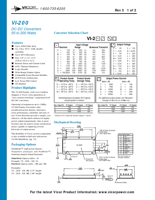
12 1-800-735-620070Converter Selection ChartVI-2Mechanical DrawingFeaturess Up to 50W/Cubic Inchs UL, CSA, TÜV, VDE, BABT, AUSTELs Up to 90% Efficiency s Size: 4.6" x 2.4" x 0.5"(116,8 x 61,0 x 12,7)s Remote Sense and Current Limit s OVP, Thermal Shutdown s Logic Disables Wide Range Output Adjusts Compatible Power Booster Modules s ZCS Power Architecture s Low Noise FM Control s CE MarkedVI-200DC-DC Converters 50 to 200 WattsProduct HighlightsThe VI-200 Family, with over 8 millionshipped, is Vicor’s first generation of“zero-current-switching” component-level DC-DC converters.Operating at frequencies up to 2 MHz, VI-200 Family Converters offerexceptional power density, efficiency,noise performance, reliability and ease of use. Power Boosters provide a simple, cost effective, off-the-shelf solution for higher power output requirements. One or more boosters may be used to create synchronous arrays capable of supplying several kilowatts of output power.The flexibility of Vicor’s power components is also available in half-size, half-power VI-J00 MiniMods. (pg. 72)Packaging OptionsSlimMods™, high power density,flangeless packages and FinMods™,featuring integral finned heatsinks.SlimMod: Option suffix: - S Example: VI - 2XX - XX - SFinMod: Option suffix: - F1and - F2Examples:VI - 2XX - XX -F1, 0.75" height VI - 2XX - XX -F2, 1.00" heightMax. Output For 5V Outputs > 5V Outputs< 5V Outputs(1)75W 75W 15A (2)150W 150W 30A (3)100W100W20A* Brownout 75% of rated load; transient voltage for 1 second.Max. Output For 5V Outputs > 5V Outputs < 5V Outputs(4)200W 200W 40A (5)150W 200W 40A (6)75W100W20ARev 3 1 of 2For the latest Vicor Product Information: 12 1-800-735-620071VI-200 E-GradeVI-200 C-, I-, M-Grade PARAMETERMIN.TYP.MAX.MIN.TYP.MAX.UNITSTEST CONDITIONSs Input Characteristics Inrush charge120x10-6120x10-6200x10-6CoulombsNominal lineInput reflected ripple current – pp 10%10%I INNominal line, full load Input ripple rejectiondB 120 Hz, nominal line dB 2400 Hz, nominal lineNo load power dissipation 1.3521.352Wattss Output Characteristics Setpoint accuracy 1%2%0.5%1%V NOM Load/line regulation 0.5%0.05%0.2%V NOM LL to HL, 10% to Full Load Load/line regulation 1%0.2%0.5%V NOM LL to HL, No Load to 10%Output temperature drift 0.020.010.02% / °C Over rated temp.Long term drift 0.020.02%/1K hoursOutput ripple - pp: 2V, 3.3V 150 mV 60 mV 100 mV 20 MHz bandwidth 5V 5%2%3%20 MHz bandwidth 10-48V 3%0.75%1.5%20 MHz bandwidth Trim range 150%110%50%110%Total remote sense compensation 0.50.5Volts 0.25V max. neg. leg OVP set point 125%2115%125%2135%V NOM Recycle power Current limit105%135%105%125%I NOM Automatic restartShort circuit current 320%140%20%130%I NOMs Control Pin Characteristics Gate out impedance 5050Ohms Gate in impedance103103Ohms Gate in open circuit voltage 66Volts Use open collectorGate in low threshold 0.650.65Volts Gate in low current 66mAPower sharing accuracy 0.951.050.951.05s Dielectric Withstand Characteristics Input to output 3,0003,000V RMS Baseplate earthedOutput to baseplate 500500V RMS Input to baseplate 1,5001,500V RMSs Thermal Characteristics Efficiency78-88%80-90%Baseplate to sink 0.20.2°C/Watt With Vicor P/N 01777Thermal shutdown 490951059095105°CCool and recycle power (Drivers only)to restarts Mechanical Specifications Weight6.0 (170) 6.0 (170)Ounces (Grams)110V, 12V and 15V outputs, standard trim range ±10%. Consult factory for wider trim range. 2131% nominal for booster modules.3Output voltages of 3.3V or 5V incorporate foldback current limiting; all other outputs provide constant current limiting.4No overtemp protection in booster modules.Converter Specifications(typical at T BP =25°C, nominal line and 75% load, unless otherwise specified)25+20Log ( Vin)Vout30+20Log ( Vin)Vout20+20Log ( Vin)Rev 3 2 of 2For the latest Vicor Product Information: 。
evolution 201技术参数

文章标题:深度解读Evolution 201技术参数随着科学技术的不断发展,Evolution 201在技术参数方面一直处于领先地位。
本文将深度解读Evolution 201的技术参数,帮助读者全面理解该产品的性能和功能。
1. Evolution 201的外观设计Evolution 201作为一款先进的产品,其外观设计经过精心打磨,符合人体工程学原理,让人们在使用时感到舒适。
其外壳采用高强度材料制成,具有良好的耐磨性和耐高温性能,确保产品的长期稳定运行。
2. 技术规格与参数Evolution 201采用了先进的技术规格与参数,包括但不限于:- 高性能处理器:搭载了行业领先的处理器芯片,运行速度快,处理效率高,能够满足用户对大型软件和多任务处理的需求。
- 大内存容量:内存容量达到了XXGB,能够轻松应对多种复杂任务同时进行的需求,保证系统的稳定运行。
- 高分辨率显示屏:配备了高分辨率的显示屏,让用户在使用时能够获得更清晰、更细腻的视觉体验。
- 大容量电池:内置了大容量电池,能够满足长时间使用的需求,提升用户的使用体验。
3. 功能与性能Evolution 201在功能与性能上也表现出色,具有以下特点:- 多种应用场景适配:不论是办公、娱乐还是创作,Evolution 201都能够满足用户的需求,提供多种使用场景的适配支持。
- 快速启动和响应:处理器性能优越,保证设备的快速启动和响应速度,增加用户的使用效率。
- 高速数据传输:搭载了先进的数据传输技术,能够实现高速的数据传输和处理,满足用户对大容量数据的存储和传输需求。
4. 个人观点与理解在我看来,Evolution 201的技术参数非常全面,既满足了性能要求,又兼顾了用户体验。
其外观设计精美,技术规格与参数也处于行业领先地位,对用户来说是一款非常值得信赖的产品。
我期待着未来能够看到更多类似Evolution 201这样的高性能产品的问世,为人们的生活带来更多便利和乐趣。
NSV40201LT1G;中文规格书,Datasheet资料

US1中文资料

US1中文资料DISCRETE SEMICONDUCTORS DATA SHEETbook, halfpageM3D168US1 seriesSMA ultra fast low-losscontrolled avalanche rectifiersProduct speci?cation2000Feb14controlled avalanche recti?ersUS1 seriesFEATURESGlass passivatedHigh maximum operating temperatureIdeal for surface mount automotive applications ?Low leakage currentExcellent stabilityGuaranteed avalanche energy absorption capability ?UL94V-O classified plastic packageShipped in 12mm embossed tapeMarking: cathode, date code, type codeEasy pick and place.DESCRIPTIONDO-214AC surface mountable package with glass passivated chip.The well-defined void-free case is of a transfer-moulded thermo-setting plastic.The small rectangular package has two J bent leads.olumnsMSA474 Top view Side viewcathodebandk aFig.1 Simplified outline (DO-214AC) and symbol.LIMITING VALUESIn accordance with the Absolute Maximum Rating System (IEC134).SYMBOL PARAMETER CONDITIONS MIN.MAX.UNIT V RRM repetitive peak reverse voltageUS1A?50VUS1B?100VUS1D?200VUS1G?400VUS1J?600VV R continuous reverse voltageUS1A?50VUS1B?100VUS1D?200VUS1G?400VUS1J?600VV RMS root mean square voltageUS1A?35VUS1B?70VUS1D?140VUS1G?280VUS1J?420VI F(AV)average forward current averaged over any 20ms period;T tp=110°C; see Fig.21Acontrolled avalanche recti?ersUS1 seriesELECTRICAL CHARACTERISTICS T j =25°C unless otherwise speci?ed.THERMAL CHARACTERISTICS Notes1.Device mounted on Al 2O 3 printed-circuit board, 0.7mm thick; thickness of copper ≥35μm.2.Device mounted on epoxy-glass printed-circuit board, 1.5mm thick; thickness of copper ≥40μm. For moreinformation please refer to the ‘General Part of associated Handbook’.I FSMnon-repetitive peak forward currentt =8.3ms half sine wave;T j =25°C prior to surge;V R =V RRMmax ?25AT stg storage temperature ?65+175°C T jjunction temperatureSee Fig.365+175°CSYMBOL PARAMETER CONDITIONSTYP .MAX.UNITV Fforward voltage I F =1A;US1A to US1G see Fig.4? 1.1V US1J see Fig.51.4V I R reverse current V R =V RRMmax ; see Figs 6and 710μA V R =V RRMmax ; T j =165°C; see Figs 6and 7?50μA trr reverse recovery time when switched from I F =0.5A to I R =1A;measured at I R =0.25A; see Fig.12?50nsC ddiode capacitance V R =4V; f =1MHz;US1A to US1G see Fig.814?pF US1Jsee Fig.910pFSYMBOL PARAMETERCONDITIONSVALUE UNIT R th j-tp thermal resistance from junction to tie-point; see Fig.1027K/W R th j-a thermal resistance from junction to ambientnote 1100K/W note 2150K/WSYMBOL PARAMETERCONDITIONSMIN.MAX.UNITcontrolled avalanche recti?ersUS1 seriesGRAPHICAL DATAhandbook, halfpage 04020021.50.5180T tp (°C)I F(AV)(A)120160MCD822Fig.2Maximum permissible average forward current as a function of tie-pointtemperature (including losses due to reverse leakage).V R =V RRMmax ;δ=0.5; a =1.57.handbook, halfpage0100V R (%V Rmax )T j (°C)20010050MBK455Device mounted as shown in Fig.11.Solid line: Al 2O 3 printed-circuit board.Dotted line: epoxy printed-circuit board.Fig.3Maximum permissible junction temperature as a function of reverse voltage.handbook, halfpage32V F (V)I F(A)10MCD79210210110?110?210?3US1A to G T j =25°C.Fig.4Forward current as a function of forward voltage; typical values.handbook, halfpage42I F (A)V F (V)103MCD79310210110?110?210?3US1JT j =25°C.Fig.5Forward current as a function of forward voltage; typical values.controlled avalanche recti?ersUS1 serieshandbook, halfpage10002040V R (%V Rmax )I R (μA)608010210110?110?210?3MCD807T j = 165 °CT j = 25 °CFig.6Reverse current as a function of reverse voltage; typical values.US1A to Gf =1MHz; T j =25°C.handbook, halfpage10002040V R (%V Rmax )I R (μA)608010210110?110?210?3MCD806T j = 165 °CT j = 25 °CFig.7Reverse current as a function of reverse voltage; typical values.US1Jf =1MHz; T j =25°C.handbook, halfpage102101MCD79810?210?11V R (V)C d (pF)10102Fig.8Diode capacitance as a function of reverse voltage; typical values.US1 A to Gf =1MHz; T j =25°C.handbook, halfpage102101MCD79710?210?11V R (V)C d (pF)10102US1Jf =1MHz; T j =25°C.Fig.9Diode capacitance as a function of reverse voltage; typical values.controlled avalanche recti?ersUS1 serieshandbook, halfpage102101MBL120110Z th j-tp (K/W)102103t p (ms)104Fig.10Transient thermal impedance as a functionof pulse width.MSB2134.52.51.255050Fig.11 Printed-circuit board for surface mounting.Dimensions in mm.Material: Al 2O 3 or epoxy-glass.handbook, full pagewidth10 ?1 ?50 ?25 VDUT MAM057+t rr0.500.51.0I F (A)I R (A)t0.25Fig.12 Test circuit and reverse recovery time waveform and definition.Input impedance oscilloscope: 1M ?, 22pF; t r ≤7ns.Source impedance: 50?; t r ≤15ns.controlled avalanche recti?ersUS1 seriesPACKAGE OUTLINEREFERENCESOUTLINE VERSION EUROPEAN PROJECTIONISSUE DATE IECJEDEC EIAJSOD12499-10-22DO-214AC0 2.5 5 mmscaleTransfer-moulded thermo-setting plastic small rectangular surface mounted package;2 connectorsSOD124UNIT b A 1c D E Q mm1.61.40.20.052.82.44.54.3H 5.55.13.32.7DIMENSIONS (mm are the original dimensions)A 2.32.0DH AE b(1)A 1QcNote1. The marking band indicates the cathode.controlled avalanche recti?ersUS1 seriesDEFINITIONS LIFE SUPPORT APPLICATIONSThese products are not designed for use in life support appliances, devices, or systems where malfunction of these products can reasonably be expected to result in personal injury. Philips customers using or selling these products for use in such applications do so at their own risk and agree to fully indemnify Philips for any damages resulting from such improper use or sale.Data sheet status Objective speci?cation This data sheet contains target or goal speci?cations for product development.Preliminary speci?cation This data sheet contains preliminary data; supplementary data may be published later.Product speci?cation This data sheet contains ?nal product speci?cations.Limiting valuesLimiting values given are in accordance with the Absolute Maximum Rating System (IEC 60134).Stress above one or more of the limiting values may cause permanent damage to the device. These are stress ratings only and operation of the device at these or at any other conditions above those given in the Characteristics sections of the speci?cation is not implied. Exposure to limiting values for extended periods may affect device reliability.Application informationWhere application information is given, it is advisory and does not form part of the speci?cation.US1 series controlled avalanche recti?ersNOTESUS1 series controlled avalanche recti?ersNOTESUS1 series controlled avalanche recti?ersNOTESPhilips Electronics N.V.SCA All rights are reserved. Reproduction in whole or in part is prohibited without the prior written consent of the copyright owner.The information presented in this document does not form part of any quotation or contract,is believed to be accurate and reliable and may be changed without notice. No liability will be accepted by the publisher for any consequence of its use. Publication thereof does not convey nor imply any license under patent- or other industrial or intellectual property rights.Internet:/doc/2ec84a2e0722192e4536f6ec.html 200069Philips Semiconductors – a worldwide companyFor all other countries apply to: Philips Semiconductors,International Marketing &Sales Communications, Building BE-p, P.O.Box 218,5600MD EINDHOVEN, The Netherlands,Fax.+31402724825Argentina: see South America Australia: 3 Figtree Drive, HOMEBUSH, NSW 2140,Tel.+61297048141,Fax.+61297048139Austria:Computerstr. 6, A-1101 WIEN, P.O. Box 213,Tel.+431601011248, Fax.+431601011210Belarus: Hotel Minsk Business Center, Bld.3, r.1211, Volodarski Str.6,220050MINSK, Tel.+375172200733,Fax.+375172200773Belgium: see TheNetherlands Brazil:see South AmericaBulgaria:Philips Bulgaria Ltd., Energoproject, 15th floor,51James Bourchier Blvd., 1407SOFIA,T el.+3592689211,Fax.+3592689102Canada: PHILIPS SEMICONDUCTORS/COMPONENTS,T el.+18002347381,Fax.+18009430087China/Hong Kong: 501Hong Kong Industrial Technology Centre,72Tat Chee Avenue, Kowloon Tong, HONG KONG,Tel.+852********,Fax.+852********Colombia: see South America Czech Republic: see AustriaDenmark: Sydhavnsgade 23, 1780COPENHAGEN V,Tel.+4533293333,Fax.+4533293905Finland: Sinikalliontie 3, FIN-02630ESPOO,T el.+3589615800,Fax.+358961580920 France: 51Rue Carnot, BP317, 92156SURESNES Cedex,Tel.+33140996161,Fax.+33140996427Germany: Hammerbrookstra?e 69, D-20097HAMBURG,T el.+4940235360,Fax.+494023536300Hungary: see AustriaIndia: Philips INDIA Ltd, Band Box Building, 2nd floor,254-D,Dr.Annie Besant Road, Worli, MUMBAI 400025,Tel.+91224938541,Fax.+91224930966Indonesia:PT Philips Development Corporation,Semiconductors Division,Gedung Philips, Jl. Buncit Raya Kav.99-100, JAKARTA 12510,Tel.+62217940040ext.2501, Fax.+62217940080Ireland: Newstead, Clonskeagh, DUBLIN 14,Tel.+35317640000,Fax.+35317640200Israel: RAPAC Electronics, 7Kehilat Saloniki St, PO Box 18053,TEL AVIV 61180, Tel.+97236450444,Fax.+97236491007Italy:PHILIPS SEMICONDUCTORS,Via Casati,23-20052MONZA (MI),Tel. +390392036838,Fax +390392036800 Japan: Philips Bldg 13-37, Kohnan 2-chome, Minato-ku,TOKYO 108-8507, Tel.+81337405130,Fax.+81337405057Korea: Philips House, 260-199Itaewon-dong, Yongsan-ku, SEOUL,Tel.+8227091412,Fax.+8227091415Malaysia: No.76Jalan Universiti, 46200PETALING JAYA, SELANGOR,Tel.+60 37505214,Fax.+6037574880Mexico: 5900Gateway East, Suite 200, EL PASO, TEXAS 79905,Tel.+9-58002347381, Fax +9-58009430087Middle East: see ItalyNetherlands: Postbus 90050, 5600PB EINDHOVEN, Bldg.VB,Tel.+31402782785,Fax.+31402788399New Zealand: 2Wagener Place, C.P.O.Box 1041, AUCKLAND,Tel.+6498494160,Fax.+6498497811Norway: Box 1, Manglerud 0612, OSLO,Tel.+4722748000,Fax.+4722748341Pakistan: see Singapore Philippines: Philips Semiconductors Philippines Inc.,106Valero St.Salcedo Village, P.O.Box 2108MCC,MAKATI,Metro MANILA, Tel.+6328166380,Fax.+6328173474Poland : Al.Jerozolimskie 195B,02-222WARSAW,Tel.+48225710000,Fax.+48225710001Portugal: see Spain Romania: see ItalyRussia: Philips Russia, /doc/2ec84a2e0722192e4536f6ec.html atcheva 35A, 119048MOSCOW,Tel.+70957556918,Fax.+70957556919 Singapore: Lorong 1, Toa Payoh, SINGAPORE 319762,Tel.+653502538,Fax.+652516500Slovakia: see AustriaSlovenia: see ItalySouth Africa: S.A. PHILIPS Pty Ltd., 195-215Main Road Martindale,2092JOHANNESBURG, P.O.Box 58088 Newville 2114,Tel.+27114715401,Fax.+27114715398South America: Al.Vicente Pinzon,173, 6th floor,04547-130S?O PAULO,SP, Brazil,Tel.+55118212333,Fax.+55118212382Spain: Balmes 22, 08007BARCELONA,Tel.+34933016312,Fax.+34933014107 Sweden: Kottbygatan 7, Akalla, S-16485STOCKHOLM,Tel.+46859852000,Fax.+46859852745 Switzerland: Allmendstrasse 140, CH-8027ZüRICH,Tel.+4114882741Fax.+4114883263Taiwan: Philips Semiconductors, 6F, No.96, Chien Kuo N.Rd.,Sec.1,TAIPEI, Taiwan Tel.+886221342886,Fax.+886221342874Thailand: PHILIPS ELECTRONICS (THAILAND) Ltd.,209/2Sanpavuth-Bangna Road Prakanong, BANGKOK 10260,Tel.+6627454090,Fax.+6623980793Turkey: Yukari Dudullu, Org. San. Blg., 2.Cad. Nr. 28 81260Umraniye,ISTANBUL,Tel.+902165221500,Fax.+902165221813Ukraine : PHILIPS UKRAINE, 4Patrice Lumumba str., Building B, Floor 7,252042KIEV, Tel.+380442642776, Fax. +380442680461 United Kingdom: Philips Semiconductors Ltd., 276Bath Road, Hayes,MIDDLESEX UB35BX, Tel.+442087305000,Fax.+442087548421United States: 811East Arques Avenue, SUNNYVALE, CA 94088-3409,Tel.+18002347381, Fax.+18009430087Uruguay: see South AmericaVietnam: see SingaporeYugoslavia: PHILIPS, Trg N. Pasica 5/v,11000BEOGRAD,Tel.+381113341299,Fax.+381113342553 Printed in The Netherlands603502/250/01/pp 12 Date of release:2000Feb 14Document order number: 939775006784。
DRV201YFMT;DRV201YFMR;DRV201EVM;中文规格书,Datasheet资料
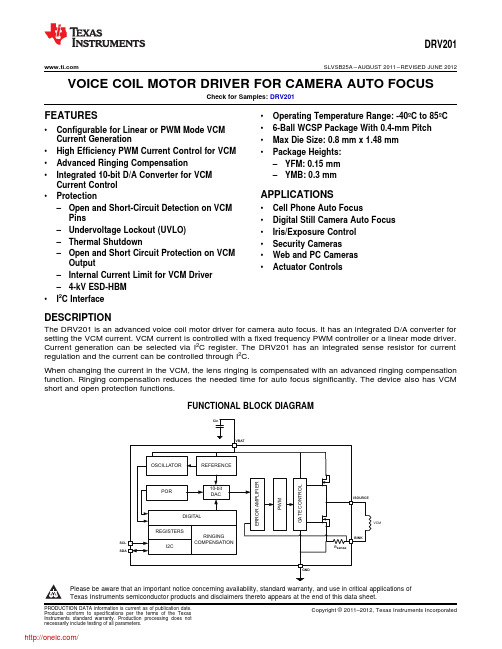
VCMDRV201 SLVSB25A–AUGUST2011–REVISED JUNE2012 VOICE COIL MOTOR DRIVER FOR CAMERA AUTO FOCUSCheck for Samples:DRV201FEATURES•Operating Temperature Range:-40ºC to85ºC•6-Ball WCSP Package With0.4-mm Pitch •Configurable for Linear or PWM Mode VCMCurrent Generation•Max Die Size:0.8mm x1.48mm•High Efficiency PWM Current Control for VCM•Package Heights:•Advanced Ringing Compensation–YFM:0.15mm•Integrated10-bit D/A Converter for VCM–YMB:0.3mmCurrent ControlAPPLICATIONS•Protection–Open and Short-Circuit Detection on VCM•Cell Phone Auto FocusPins•Digital Still Camera Auto Focus –Undervoltage Lockout(UVLO)•Iris/Exposure Control–Thermal Shutdown•Security Cameras–Open and Short Circuit Protection on VCM•Web and PC CamerasOutput•Actuator Controls–Internal Current Limit for VCM Driver–4-kV ESD-HBM•I2C InterfaceDESCRIPTIONThe DRV201is an advanced voice coil motor driver for camera auto focus.It has an integrated D/A converter for setting the VCM current.VCM current is controlled with a fixed frequency PWM controller or a linear mode driver. Current generation can be selected via I2C register.The DRV201has an integrated sense resistor for current regulation and the current can be controlled through I2C.When changing the current in the VCM,the lens ringing is compensated with an advanced ringing compensation function.Ringing compensation reduces the needed time for auto focus significantly.The device also has VCM short and open protection functions.FUNCTIONAL BLOCK DIAGRAMPlease be aware that an important notice concerning availability,standard warranty,and use in critical applications ofTexas Instruments semiconductor products and disclaimers thereto appears at the end of this data sheet.PRODUCTION DATA information is current as of publication date.Copyright©2011–2012,Texas Instruments Incorporated Products conform to specifications per the terms of the TexasInstruments standard warranty.Production processing does notnecessarily include testing of all parameters.CB A21NanoFree YFM PACKAGE(BOTTOM VIEW)YMB package package markings:YM =YEAR /MONTH DATE CODE D =DAY OF LASER MARK S =ASSEMBLY SITE CODE 0=Pin A1(Filled Solid)NanoFree YMB PACKAGE(TOP VIEW)NanoFree YFM PACKAGE(TOP VIEW)C B A21NanoFree YMB PACKAGE(BOTTOM VIEW)YFM package has no top side markingsDRV201SLVSB25A –AUGUST 2011–REVISED JUNE 2012This integrated circuit can be damaged by ESD.Texas Instruments recommends that all integrated circuits be handled with appropriate precautions.Failure to observe proper handling and installation procedures can cause damage.ESD damage can range from subtle performance degradation to complete device failure.Precision integrated circuits may be more susceptible to damage because very small parametric changes could cause the device not to meet its published specifications.ORDERING INFORMATION (1)T APACKAGE (2)ORDERABLE PART NUMBERYFM DRV201YFMR -40°C to 85°CYMBDRV201YMBR(1)For the most current package and ordering information,see the Package Option Addendum at the end of this document,or see the TI web site at .(2)Package drawings,thermal data,and symbolization are available at /packaging .DEVICE INFORMATIONTERMINAL FUNCTIONSTERMINAL I/ODESCRIPTIONNAME NO.VBAT 2A Power GND 1A GroundI_SOURCE 2B Voice coil positive terminal I_SINK 1B Voice coil negative terminal SCL 2C I I 2C serial interface clock inputSDA1CI/O I 2C serial interface data input/output (open drain)2Submit Documentation FeedbackCopyright ©2011–2012,Texas Instruments IncorporatedProduct Folder Link(s):DRV201DRV201 SLVSB25A–AUGUST2011–REVISED JUNE2012ABSOLUTE MAXIMUM RATINGSover operating free-air temperature range(unless otherwise noted)(1)VALUE UNIT VBAT,ISOURCE,ISOURCE pin voltage range(2)–0.3to5.5VVoltage range at SDA,SCL–0.3to3.6VContinuous total power dissipation Internally limitedθJA Junction-to-ambient thermal resistance(3)130°C/WT J Operating junction temperature-40to125°CT A Operating ambient temperature-40to85°CT stg Storage temperature-55to150°C(HBM)Human body model±4000ESD rating V(CDM)Charged device model±500(1)Stresses beyond those listed under Absolute Maximum Ratings may cause permanent damage to the device.These are stress ratingsonly,and functional operation of the device at these or any other conditions beyond those indicated under Recommended Operating Conditions is not implied.Exposure to absolute maximum rated conditions for extended periods may affect device reliability.(2)All voltage values are with respect to network ground terminal.(3)This thermal data is measured with high-K board(4-layer board).ELECTRICAL CHARACTERISTICSOver recommended free-air temperature range and over recommended input voltage range(typical at an ambient temperature range of25°C)(unless otherwise noted)PARAMETER TEST CONDITIONS MIN TYP MAX UNIT INPUT VOLTAGEV BAT Input supply voltage 2.5 3.7 4.8VV BAT rising 2.2V UVLO Undervoltage lockout threshold VV BAT falling2V HYS Undervoltage lockout hysteresis50100250mV INPUT CURRENTInput supply current shutdown,I SHUTDOWN MAX:V BAT=4.4V0.151µAincludes switch leakage currentsInput supply current standby,includesI STANDBY MAX:V BAT=4.4V120200µAswitch leakage currentsSTARTUP,MODE TRANSITIONS,AND SHUTDOWNt1Shutdown to standby100µst2Standby to active100µst3Active to standby100µst4Shutdown time Active or standby to shutdown0.51ms VCM DRIVER STAGEResolution10bitsI RES Relative accuracy-1010LSB Differential nonlinearity-11Zero code error0mAOffset error At code323mA%of Gain error±3FSR Gain error drift0.30.4%/°COffset error drift0.30.5%/°C I MAX Maximum output current102.3mAI LIMIT Average VCM current limit See(1)110160240mA(1)During short circuit condition driver current limit comparator will trip and short is detected and driver goes into STANDBY and short flagis set high in the status register.Copyright©2011–2012,Texas Instruments Incorporated Submit Documentation Feedback3Product Folder Link(s):DRV201DRV201SLVSB25A–AUGUST2011–REVISED ELECTRICAL CHARACTERISTICS(continued)Over recommended free-air temperature range and over recommended input voltage range(typical at an ambient temperature range of25°C)(unless otherwise noted)PARAMETER TEST CONDITIONS MIN TYP MAX UNIT Minimum VCM code for OPEN andI DETCODE See(2)256mASHORT detectionf SW Switching frequency Selectable through CONTROL register0.54MHz V DRP Internal dropout See(3)0.4VL VCM VCM inductance30150µHR VCM VCM resistance1122ΩLENS MOVEMENT CONTROLt set1Lens settling time±10%error band2/f VCM mst set2Lens settling time±10%error band1/f VCM ms VCM resonance frequency50150Hzf VCM When1/f VCM compensation is used-1010VCM resonance frequency tolerance%When2/f VCM compensation is used-3030LOGIC I/Os(SDA AND SCL)V=1.8V,SCL-4.25 4.25I IN Input leakage currentµAV=1.8V,SDA-11R PullUp I2C pull-up resistors SDA and SCL pins 4.7kΩV IH Input high level See(4) 1.17 3.6VV IL Input low level See(5)00.63Vt TIMEOUT SCL timeout for shutdown detection0.51msR PD Pull down resistor at SCL line500kΩf SCL I2C clock frequency400kHz INTERNAL OSCILLATORf OSC Internal oscillator20°C≤T A≤70°C-33%Frequency accuracy-40°C≤T A≤85°C-55% THERMAL SHUTDOWNT TRIP Thermal shutdown trip point140°C(2)When testing VCM open or short this is the recommended minimum VCM code(in dec)to be used.(3)This is the voltage that is needed for the feedback resistor and high side driver.It should be noted that the maximum VCM resistance islimited by this voltage and supply voltage.E.g.3-V supply maximum VCM resistance is:R VCM=(V BAT–V DRP)/I VCM=(3V-0.4V)/102.3mA=25.4Ω.(4)During shutdown to standby transition V IH low limit is1.28V.(5)During shutdown to standby transition V IL high limit is0.51V.4Submit Documentation Feedback Copyright©2011–2012,Texas Instruments IncorporatedProduct Folder Link(s):DRV201VCMDRV201V inDRV201SLVSB25A –AUGUST 2011–REVISED JUNE 2012PARAMETER MEASUREMENT INFORMATIONList of components:•C in -Panasonic ECJ0EB1A105M •VCM -Mitsumi VCM KAF-V85S60•Actuator size:8.5x 8.5x 3.4(mm)•Lens in the VCM:M6(Pitch:0.35)•Weight:75mg •TTL:4.2mm •FB:1.1mmCopyright ©2011–2012,Texas Instruments Incorporated Submit Documentation Feedback5Product Folder Link(s):DRV201DRV201SLVSB25A–AUGUST2011–REVISED TYPICAL CHARACTERISTICSFigure1.Lens Positions With and Without Ringing Figure2.Lens Positions With and Without RingingCompensation With100-µm Step on the Lens Position Compensation With100-µm Step on the Lens Position,Zoomed InFigure3.Lens Positions With and Without Ringing Figure4.Lens Positions With and Without RingingCompensation With30-µm Step on the Lens Position Compensation With30-µm Step on the Lens Position,Zoomed In6Submit Documentation Feedback Copyright©2011–2012,Texas Instruments IncorporatedProduct Folder Link(s):DRV201Vbat ISC/SCLmodeDAC DRV201 SLVSB25A–AUGUST2011–REVISED JUNE2012FUNCTIONAL DESCRIPTIONThe DRV201is intended for high performance autofocus in camera modules.It is used to control the current in the voice coil motor(VCM).The current in the VCM generates a magnetic field which forces the lens stack connected to a spring to move.The VCM current and thus the lens position can be controlled via the I2C interface and an auto focus function can be implemented.The device connects to a video processor or image sensor through a standard I2C interface which supports up to 400-kbit/s data rate.The digital interface supports IO levels from1.8V to3.3V.All pins have4-kV HBM ESD rating.When SCL is low for at least0.5ms,the device enters SHUTDOWN mode.If SCL goes from low to high the driver enters STANDBY mode in less than100μs and default register values are set as shown in Figure5. ACTIVE mode is entered whenever the VCM_CURRENT register is set to something else than zero.Figure5.Power Up and Down SequenceVCM current can be controlled via an I2C interface and VCM_CURRENT registers.Lens stack is connected to a spring which causes a dampened ringing in the lens position when current is changed.This mechanical ringing is compensated internally by generating an optimized ramp whenever the current value in the VCM_CURRENT register is changed.This enables a fast autofocus algorithm and pleasant user experience.Current in the VCM can be generated with a linear or PWM control.In linear mode the high side PMOS is configured as a current source and current is set by the VCM_CURRENT control register.In PWM control the VCM is driven with a half bridge driver.With PWM control the VCM current is increased by connecting the VCM between V BAT and GND through the high side PMOS and then released to a‘freewheeling’mode through the sense resistor and low side NMOS.PWM mode switching frequency can be selected from0.5MHz up to4MHz through a CONTROL register.PWM or linear mode can be selected with the PWM/LIN bit in the MODE register.Copyright©2011–2012,Texas Instruments Incorporated Submit Documentation Feedback7Product Folder Link(s):DRV201DRV201SLVSB25A–AUGUST2011–REVISED MODES OF OPERATIONSHUTDOWN If the driver detects SCL has a DC level below0.63V for duration of at least0.5ms,the driver will enter shutdown mode.This is the lowest power mode of operation.The driver will remain in shutdown for as long as SCL pin remain low.STANDBY If SCL goes from low to high the driver enters STANDBY mode and sets the default register values.In this mode registers can be written to through the I2C interface.Device will be in STANDBY mode when VCM_CURRENT register is set to zero.From ACTIVE mode the device will enter STANDBY if theSW_RST bit of the CONTROL register is set.In this case all registers will be reset to default values.STANDBY mode is entered from ACTIVE mode if any of the following faults occur:Overtemperature protection fault(OTPF),VCM short(VCMS),or VCM open(VCMO).WhenSTANDBY mode is entered due to a fault condition current register is cleared.ACTIVE The device is in ACTIVE mode whenever the VCM_CURRENT control is set to something else than zero through the I2C interface.In ACTIVE mode VCM driver output stage is enabled all the time resulting in higher power consumption.The device remains in active mode until the SW_RST bit in the CONTROL register is set,SCL is pulled low for duration of0.5ms,VCM_CURRENT control is set to zero,or any of the following faults occur:Over temperature protection fault(OTPF),VCM short(VCMS),or VCM open (VCMO).If active mode is entered after fault the status register is automatically cleared.8Submit Documentation Feedback Copyright©2011–2012,Texas Instruments IncorporatedProduct Folder Link(s):DRV201DRV201 SLVSB25A–AUGUST2011–REVISED JUNE2012VCM DRIVER OUTPUT STAGE OPERATIONCurrent in the VCM can be controlled with a linear or PWM mode output stage.Output stage is enabled in ACTIVE mode which can be controlled through VCM_CURRENT control register and the output stage mode is selected from MODE register bit PWM/LIN.In linear mode the output PMOS is configured to a high side current source and current can be controlled from a VCM_CURRENT registers.In PWM control the VCM is driven with a half bridge driver.With PWM control the VCM current is increased by connecting the VCM between V BAT and GND through the high side PMOS and then released to a‘freewheeling’mode through the sense resistor and low side NMOS.Current in the VCM is sensed with a1-Ωsense resistor which is connected into an error amplifier input where the other input is controlled by the10-bit DAC output. PWM mode switching frequency can be selected from0.5MHz up to4MHz through a CONTROL register.PWM or linear mode can be selected with the PWM/LIN bit in the MODE register.RINGING COMPENSATIONVCM current can be controlled via an I2C interface and VCM_CURRENT registers.Lens stack is connected to a spring which causes a dampened ringing in the lens position when current is changed.This mechanical ringing is compensated internally by generating an optimized ramp whenever the current value in the VCM_CURRENT register is changed.This enables a fast auto focus algorithm and pleasant user experience.Ringing compensation is dependent on the VCM resonance frequency and this can be controlled via VCM_FREQ register(07h)from50Hz up150Hz.Table1shows the VCM_FREQ register setting for each resonance frequency in1-Hz steps.If more accurate resonance frequency is available,the control value can be calculated with Equation1.Ringing compensation is designed in a way that it can tolerate±30%frequency variation in the VCM resonance frequency when2/f VCM compensation is used and±10%variation with1/f VCM so only statistical data from the VCM is needed in production.Copyright©2011–2012,Texas Instruments Incorporated Submit Documentation Feedback9Product Folder Link(s):DRV201DRV201SLVSB25A–AUGUST2011–REVISED Table1.VCM Resonance Frequency Control Register(07h)Table VCM VCM_FREQ[7:0](07h)VCM VCM_FREQ[7:0](07h)VCM VCM_FREQ[7:0](07h) Resonance Resonance ResonanceFrequency Frequency FrequencyDEC BIN DEC BIN DEC BIN [Hz][Hz][Hz]50008415410011010118220110111005171118515710011101119222110111105214111086160101000001202231101111153211010187162101000101212241110000054271101188165101001011222261110001055341000108916710100111123227111000115640101000901701010101012422811100100574610111091172101011001252291110010158521101009217410101110126231111001115958111010931771011000112723211101000606311111194179101100111282331110100161681000100951811011010112923411101010627310010019618310110111130235111010116378100111097185101110011312361110110064831010011981871011101113223811101110658810110009918910111101133239111011116692101110010019110111111134240111100006796110000010119311000001135241111100016810111001011021951100001113624211110010691051101001103197110001011372431111001170109110110110419811000110138244111101007111311100011052001100100013924511110101721161110100106202110010101402461111011073120111100010720411001100141247111101117412411111001082051100110114224811111000751271111111109207110011111432491111100176130100000101102081101000014425011111010771341000011011121011010010145251111110117813710001001112212110101001462511111101179140100011001132131101010114725211111100801431000111111421511010111148253111111018114610010010115216110110001492541111111082149100101011162171101100115025511111111831521001100011721911011011---10Submit Documentation Feedback Copyright©2011–2012,Texas Instruments IncorporatedProduct Folder Link(s):DRV201分销商库存信息:TIDRV201YFMT DRV201YFMR DRV201EVM。
SC-201资料

32
32
32
XpressFlow Bus Interafce
32
Mngmt
Bus
Interface
32
32
32
Automatic Buffer
Manager
2.1 Related Components:
EA-208 – 6-port 10 + 2-port
10/100 Ethernet Access Controller
System Block Diagram – 18-Port Ethernet Switch with 2 Fast Ethernet Up-Links
© 1997 9(57(; 1(7:25.6
Page: 2
Rev. 4.1 – December, 1997
PRELIMINARY
XpressFlow™ 2001 Series – Ethernet Switch Chipset
Table
Buffer RAM
SC201 XpressFlow
Engine
RS232 Local Control Console
Flash ROM
Switch Manager
CPU
Management Bus
DRAM
XpressFlow Bus
Buffer RAM
EA208E 8-Port Ethernet Access Controller
1. DISTINCTIVE CHARACTERISTICS
Highly integrated central switch controller State of the art 0.5 micron 3.3 Volt CMOS
VISONIC无线报警主机编程手册(中文)概要

1.2 进入安装菜单〃〃〃〃〃〃〃〃〃 2 6.5 第一帐户号〃〃〃〃〃〃〃〃〃 122. 设臵新安装密码〃〃〃〃〃〃〃〃〃〃 3 6.6 第二中心站电话〃〃〃〃〃〃〃123. 注册无线装臵和Keyfob遥控器〃〃〃 3 6.7 第二帐户号〃〃〃〃〃〃〃〃〃123.1一般指南〃〃〃〃〃〃〃〃〃〃〃 3 6.8 报告格式〃〃〃〃〃〃〃〃〃〃 12 3.2 无线装臵〃〃〃〃〃〃〃〃〃〃〃 3 6.9 4/2 脉冲率〃〃〃〃〃〃〃〃〃 12 3.3 Keyfob遥控器〃〃〃〃〃〃〃〃 3 6.10 报告中心站〃〃〃〃〃〃〃〃 123.4 删除装臵和Keyfob 的识别代码〃 4 6.11 拨号尝试〃〃〃〃〃〃〃〃〃 134. 定义防区类型〃〃〃〃〃〃〃〃〃〃〃 5 6.12 第一私人电话号码〃〃〃〃〃144.1 初步指南〃〃〃〃〃〃〃〃〃〃〃 5 6.13 第二私人电话号码〃〃〃〃〃 144.2 防区定义流程〃〃〃〃〃〃〃〃〃 5 6.14 第三私人电话号码〃〃〃〃〃 145. 定义控制面板参数〃〃〃〃〃〃〃〃〃 56.15 电话讯息类型〃〃〃〃〃〃〃145.1初步指南〃〃〃〃〃〃〃〃〃〃〃 66.16 私人电话拨号尝试〃〃〃〃〃 14 5.2 进入延时〃〃〃〃〃〃〃〃〃〃〃 7 6.17 报告私人电话〃〃〃〃〃〃〃 14 5.3 退出延时〃〃〃〃〃〃〃〃〃〃〃 7 6.18 电话确认〃〃〃〃〃〃〃〃〃 14 5.4 警铃时间〃〃〃〃〃〃〃〃〃〃〃 8 6.19 传呼台电话号码〃〃〃〃〃〃 14 5.5 报警缓冲时间〃〃〃〃〃〃〃〃〃 8 6.20 传呼机PIN密码〃〃〃〃〃〃 14 5.6 警报取消时间〃〃〃〃〃〃〃〃〃 5 6.21向传呼机报告内容〃〃〃〃〃 14 5.7 快速警戒〃〃〃〃〃〃〃〃〃〃〃 6 6.22 最近关门报告设臵〃〃〃〃〃 14 5.8 绕过〃〃〃〃〃〃〃〃〃〃〃〃〃 6 6.23 远程登陆许可设臵〃〃〃〃〃 14 5.9 重新启动退出延时〃〃〃〃〃〃〃 7 6.24 上载密码设臵〃〃〃〃〃〃〃 15 5.10 电声警示〃〃〃〃〃〃〃〃〃〃 77. 定义输出参数〃〃〃〃〃〃〃〃〃〃155.11 故障警示〃〃〃〃〃〃〃〃〃〃 8 7.1初步指南〃〃〃〃〃〃〃〃〃〃 15 5.12 恐慌报警〃〃〃〃〃〃〃〃〃〃 8 7.2 PGM输出控制〃〃〃〃〃〃〃〃 16 5.13 周期性警报停止〃〃〃〃〃〃〃 5 7.3控制X-10模块〃〃〃〃〃〃〃 16 5.14 交互防区〃〃〃〃〃〃〃〃〃〃 6 8. 录制语音〃〃〃〃〃〃〃〃〃〃〃 17 5.15 监控间隔〃〃〃〃〃〃〃〃〃〃 6 8.1模式描述和激活〃〃〃〃〃〃〃 17 5.16 AUX按钮〃〃〃〃〃〃〃〃〃〃 7 8.2 录制流程〃〃〃〃〃〃〃〃〃〃 17 5.17 阻塞探测〃〃〃〃〃〃〃〃〃〃 7 9. 诊断测试〃〃〃〃〃〃〃〃〃〃〃〃175.18 双向语音-私人电话〃〃〃〃〃〃 8 9.1模式描述和激活〃〃〃〃〃〃〃 175.19双向语音-中心站〃〃〃〃〃〃〃 8 9.2 测试流程〃〃〃〃〃〃〃〃〃〃 17 5.20 PGM/X-10输出时间〃〃〃〃〃〃 6 10. 用户功能〃〃〃〃〃〃〃〃〃〃〃185.21 照明切断时间〃〃〃〃〃〃〃〃 6 11. 阅览事件日志〃〃〃〃〃〃〃〃〃 18 5.22 碰锁钥匙警戒〃〃〃〃〃〃〃〃 7 11.1 事件日志描述〃〃〃〃〃〃〃 18 5.23“无动静”时间〃〃〃〃〃〃〃〃 7 11.2 阅览流程〃〃〃〃〃〃〃〃〃 19 5.24 键盘背光照明〃〃〃〃〃〃〃〃 8 11.3 删除事件日志〃〃〃〃〃〃〃 19 5.25 胁迫报警(埋伏)〃〃〃〃〃〃 85.26 警号〃〃〃〃〃〃〃〃〃〃〃〃 8 附件A. 事件编码〃〃〃〃〃〃〃〃〃 206. 定义通讯参数〃〃〃〃〃〃〃〃〃〃〃 11 附件B. 编程防区类型〃〃〃〃〃〃〃 226.1 初步指南〃〃〃〃〃〃〃〃〃〃 116.2 拨号方法〃〃〃〃〃〃〃〃〃〃 12DE4540P 1前言1.1 一般指南在实际安装以前我们推荐在工作台上设定PowerMax程序。
VI-FKE6-CMX中文资料
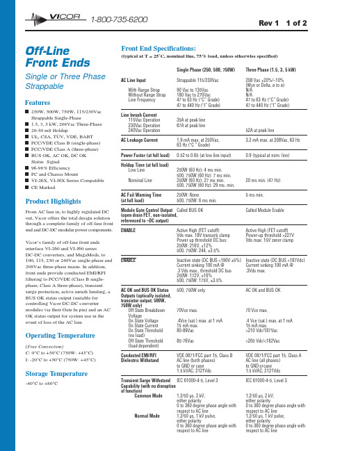
12 1-800-735-6200Features■250W, 500W, 750W, 115/230Vac Strappable Single-Phase■ 1.5, 3, 5 kW, 208Vac Three-Phase ■20-50 mS Holdup■UL, CSA, TÜV, VDE, BABT ■FCC/VDE Class B (single-phase)■FCC/VDE Class A (three-phase)■BUS OK, AC OK, DC OK Status Signal■96-98% Efficiency ■PC and Chassis Mount■VI-26X, VI-J6X Series Compatible ■CE MarkedProduct HighlightsFrom AC line in, to highly regulated DC out, Vicor offers the total design solution through a complete family of off-line front end and DC-DC modular power components.Vicor’s family of off-line front ends interface VI-260 and VI-J60 series DC-DC converters, and MegaMods, to 100, 115, 230 or 240Vac single-phase and 208Vac three-phase mains. In addition,front ends provide conducted EMI/RFI filtering to FCC/VDE (Class B single-phase, Class A three-phase), transient surge protection, active inrush limiting, a BUS OK status output (suitable for controlling Vicor DC-DC convertermodules via their Gate In pin) and an AC OK status output for system use in the event of loss of the AC line.Operating Temperature(Free Convection)C: 0°C to +50°C (750W: +45°C)I: -20°C to +50°C (750W: +45°C)Storage Temperature-40°C to +80°COff-Line Front EndsSingle or Three Phase StrappableFront End Specifications:(typical at T = 25˚C, nominal line, 75% load, unless otherwise specified)Rev 1 1 of 2107Rev 1 2 of 2For the latest Vicor Product Information: 12 1-800-735-6200INPUTOUTPUTFUSES 2,3,4...n: 3A/250V BUSSMAN PC-TRON750W — FUSE 1: 15A/250V BUSSMAN ABC-15,LITTLEFUSE 314-015FUSES 2,3,4...n: 3A/250V BUSSMAN PC-TRONFront End Selection ChartFront End Connection DiagramMounting Output Power (Watts)Model PC Chassis 250500750Single Phase VI-FPE6-CUX ■■VI-FKE6-CUX ■■VI-FPE6-CQX ■■VI-FKE6-CQX ■■VI-FPE6-CMX ■■VI-FKE6-CMX ■■Three Phase1,5003,0005,000VI-TKY6-CHX ■■VI-TKY6-CEX ■■VI-TRY6-CCX■■Notes:1.If input power is applied with the DC output BUS shorted, the active inrush circuitry will usually prevent Fuse 1 from blowing. Remove power, clear shorts, wait a few minutes and reapply input power.2.If unit is strapped for 115V operation and 230V is applied, the internal overvoltage crowbar will clear Fuse 1. Replace fuse, strap correctly and reapply power.3.To control EMI/RFI most effectively, the return path to earth ground from either the front end ormodules should be made via a good RF ground. User must assure proper grounding for safe operation.500400300200100Airflow (LFM)6004080706050500400300200100Airflow (LFM)A m b i e n t T e m p e r a t u r e °C6004080706050600500400300200100Airflow (LFM)A m b i e n t T e m p e r a t u r e °C500W750W。
DG201中文资料

DG201中文资料File Number3115.4DG201CMOS Quad SPST Analog SwitchThe DG201 solid state analog switch is designed using an improved, high voltage CMOS monolithic technology. It provides ease-of-use and performance advantages not previously available from solid state switches. Destructive latch-up of solid state analog gates have been eliminated by Intersil’s CMOS technology.The DG201 is completely speci?cation and pinout compatible with the industry standard devices.Functional DiagramFeaturesSwitches Greater than 28V P-P Signals with ±15V Supplies ?Break-Before-Make Switching-t OFF . . . . . . . . . . . . . . . . . . . . . . . . . . . . . . . . . . .250ns -t ON . . . . . . . . . . . . . . . . . . . . . . . . . . . . . . . . . . . .700ns ?TTL, DTL, CMOS, PMOS Compatible ?Non-Latching with Supply T urn-Off ?Complete Monolithic Construction ?Industry Standard (DG201)ApplicationsData AcquisitionSample and Hold CircuitsOperational Ampli?er Gain Switching NetworksPinoutDG201 (PDIP)TOP VIEWOrdering InformationPART NUMBER TEMP. RANGE(o C)PACKAGE PKG.NO.DG201CJ0 to 7016 Ld PDIPE16.3TRUTH TABLELOGIC DG2010ON 1OFFN PIN SDDG201 SWITCH CELL14151691312111012345768IN 1D 1S 1V-GND S 4IN 4D 4IN 2S 2V+(SUBSTRATE)V REF S 3D 3IN 3D 2SWITCHES SHOWN FOR LOGIC “1” INPUT Data SheetJanuary 2000元器件交易网/doc/ba14406302.html, Functional Diagram(1/4 DG201)Q3V REFINPUTGATEPROTECTIONRESISTORQ4V-Q7V+Q8Q5Q10Q12V+Q13Q11D1S1Q14Q6V-Q9Q15Q1Q2Pin DescriptionsPIN SYMBOL DESCRIPTION1IN1Logic Control for Switch 12D1Drain (Output) Terminal for Switch 1 3S1Source (Input) Terminal for Switch 1 4V-Negative Power Supply Terminal5GND Ground Terminal (Logic Common) 6S4Source (Input) Terminal for Switch 4 7D4Drain (Output) Terminal for Switch 4 8IN4Logic Control for Switch 49IN3Logic Control for Switch 310D3Drain (Output) Terminal for Switch 311S3Source (Input) Terminal for Switch 312V REF Logic Reference Voltage13V+Positive Power Supply Terminal (Substrate) 14S2Source (Input) Terminal for Switch 215D2Drain (Output) Terminal for Switch 216IN2Logic Control for Switch 2Absolute Maximum Ratings Thermal InformationV+ to V- . . . . . . . . . . . . . . . . . . . . . . . . . . . . . . . . . . . . . . . . . . . 36V V+ to V D. . . . . . . . . . . . . . . . . . . . . . . . . . . . . . . . . . . . . . . . . . . 30V V D to V- . . . . . . . . . . . . . . . . . . . . . . . . . . . . . . . . . . . . . . . . . . . 30V V D to V S. . . . . . . . . . . . . . . . . . . . . . . . . . . . . . . . . . . . . . . . . . . 28V V REF to V- . . . . . . . . . . . . . . . . . . . . . . . . . . . . . . . . . . . . . . . . . 33V V REF to V IN. . . . . . . . . . . . . . . . . . . . . . . . . . . . . . . . . . . . . . . . 30V V REF to GND. . . . . . . . . . . . . . . . . . . . . . . . . . . . . . . . . . . . . . . 20V V IN to GND . . . . . . . . . . . . . . . . . . . . . . . . . . . . . . . . . . . . . . . . 20V Current (Any Terminal). . . . . . . . . . . . . . . . . . . . . . . . . . . . . . .30mA Operating ConditionsTemperature Range“C” Suf?x . . . . . . . . . . . . . . . . . . . . . . . . . . . . . . . . . .0o C to 70o C Thermal Resistance (T ypical, Note 1)θJA (o C/W)θJC (o C/W) PDIP Package . . . . . . . . . . . . . . . . . . .90N/A Maximum Junction T emperaturePlastic Package . . . . . . . . . . . . . . . . . . . . . . . . . . . . . . . . . .150o C Maximum Storage Temperature Range. . . . . . . . . .-65o C to 150o C Maximum Lead T emperature (Soldering 10s) . . . . . . . . . . . . 300o CCAUTION:Stresses above those listed in“Absolute Maximum Ratings”may cause permanent damage to the device.This is a stress only rating and operation of the device at these or any other conditions above those indicated in the operationalsections of this speci?cation is not implied.NOTE:1.θJA is measured with the component mounted on an evaluation PC board in free air.Electrical Speci?cations T A = 25o C, V+ = +15V, V- = -15V PARAMETER TEST CONDITIONS“C” SUFFIXUNITS 0o C(NOTE 2)25o C70o CDYNAMIC CHARACTERISTICSTurn-ON Time (Note 3), t ON R L=1k?,V ANALOG=-10V to+10V(Figure1)- 1.0-μs Turn-OFF Time (Note 3), t OFF R L=1k?,V ANALOG=-10V to+10V(Figure1)-0.5-μs Charge Injection, Q Figure 2-20 (Typ)-mV Off Isolation Rejection Ratio, OIRR f = 1MHz, R L = 100?, C L≤5pF, (Figure 3)-50 (Typ)-dB Crosstalk (Channel-to-Channel), CCRR One Channel Off--50 (Typ)-dB DIGITAL INPUT CHARACTERISTICSInput Logic Current, I IN(ON)V IN = 0.8V (Note 3)±1±1±10μA Input Logic Current, I N(OFF)V IN = 2.4V (Note 3)±1±1±10μA ANALOG SWITCH CHARACTERISTICSAnalog Signal Range, V ANALOG-±15 (T yp)-V Drain-Source ON Resistance, r DS(ON)I S = 10mA, V ANALOG =±10V100100125?Channel-to-Channelr DS(ON) Match, r DS(ON)-30 (Typ)-?Drain OFF Leakage Current, I D(OFF)V ANALOG = -14V to +14V-±5100nA Source OFF Leakage Current, I S(OFF)V ANALOG = -14V to +14V-±5100nA Channel ON Leakage Current, I D(ON)+ I S(ON)V D = V S = -14V to +14V-±5200nA POWER SUPPLYCHARACTERISTICSSupply Current, I+ Positive V IN = 0V or V IN = 5V200010002000μA Supply Current, I- Negative200010002000μA NOTES:2.Typical values are for design aid only, not guaranteed and not subject to production testing.3.All channels are turned off by high“1”logic inputs and all ch annels are turned on by low“0”inputs;however0.8V to2.4V describes the minimumrange for switching properly. Peak input current required for transition is typically -120μA.Typical ApplicationsUsing the V REF TerminalThe DG201 has an internal voltage divider setting the TTL threshold on the input control lines for V+equal to +15V .The schematic shown in Figure 4 with nominal resistor values,gives approximately 2.4V on the V REF pin.As the TTL input signal goes from +0.8V to +2.4V ,Q 1and Q 2switch states to turn the switch ON and OFF . If the power supply voltage is less than +15V , then a resistor (R EXT ) must be added between V+ and the V REF pin, to restore +2.4V at V REF .The table shows the value of this resistor for various supply voltages, to maintain TTL compatibility. If CMOS logic levels with a +5V supply are being used, the threshold shifts are less critical,but a separate column of suitable values is given in the table. For logic swings of -5V to + 5V , no resistor is needed.In general, the “low” logic level should be <0.8V to prevent Q 1 and Q 2 from both being ON together (this will cause incorrect switch function).Test CircuitsFIGURE 1.t ON AND t OFF TEST CIRCUIT FIGURE 2.CHARGE INJECTION TEST CIRCUIT FIGURE 3.OFF ISOLATION TEST CIRCUIT0V3V LOGIC INPUTANALOG INPUT 10V10pFV OUT 1k ?0V3V LOGIC INPUTANALOG INPUT 10V10nFV OUTV OUT100?2V P-P AT 1MHzLOGIC INPUT 51?ANALOG INPUT3VTABLE 1.V+ SUPPLY (V)R EXT FOR TTL LEVELS (k ?)R EXT FOR CMOS LEVELS (k ?)+15--+12420-+10190-+9136136+89898+7 7070V+Q 1118k ?V REFR EXTQ 2GATE PROTECTION RESISTORINPUTFIGURE 4.Typical Performance CurvesFIGURE 5.r DS(ON) vs V D AND TEMPERATUREFIGURE 6.r DS(ON) vs V D AND POWER SUPPLY VOLTAGEFIGURE 7.I D(ON) vs TEMPERATURE FIGURE 8.I S(OFF) OR I D(OFF) vs TEMPERATURE100500-15-10-5051015D R A I N -S O U R CE O N R E S I S T A N C E (?)DRAIN VOLTAGE (V)125o C25o C -55o CV+ = +15V V- = -15V100500-15-10-5051015D R A I N -S O U R CE O N R E S I S T A N C E (?)DRAIN VOLTAGE (V)A BA:V+ = +15V , V- = -15V B:V+ = +12V , V- = -12V C:V+ = +10V , V- = -10V D:V+ = +8V , V- = -8V1010.10.01C H A N N E L O N L E A K A G E C U R R E N T (n A )25456585105125TEMPERATURE (o C)1010.10.01S O U R C E O R D R A I N O F F L E A K A G E 25456585105125TEMPERATURE (o C)C U R R E N T (n A )Die CharacteristicsDIE DIMENSIONS:94 mils x 101 mils x 14 mils METALLIZATION:Type: AlThickness: 10k?PASSIVATION:Type: SiO2/Si3N4SiO2 Thickness: 7k?Si3N4 Thickness: 8k?WORST CASE CURRENT DENSITY: 1 x 10⁵ A/cm2Metallization Mask LayoutDG201S1 (3)V- (4) GND (5)S4 (6)IN2(16)IN1(1)D1(2)(11) S3(13) V+ (SUBSTRATE)?(14) S2(15)(7)D4(8)IN4(9)IN3(10)D3D2BACKSIDE OF CHIP IS V+ (12) V REFAll Intersil semiconductor products are manufactured, assembled and tested under ISO9000 quality systems certi?cation.Intersil semiconductor products are sold by description only.Intersil Corporation reserves the right to make changes in circuit design and/or specifications at any time with-out notice.Accordingly,the reader is cautioned to verify that data sheets are current before placing /doc/ba14406302.html,rmation furnished by Intersil is believed to be accurate and reliable.However,no responsibility is assumed by Intersil or its subsidiaries for its use;nor for any infringements of patents or other rights of third parties which may result from its use. No license is granted by implication or otherwise under any patent or patent rights of Intersil or its subsidiaries.For information regarding Intersil Corporation and its products,see web site /doc/ba14406302.html, Sales Of?ce HeadquartersNORTH AMERICA Intersil CorporationP. O. Box 883, Mail Stop 53-204Melbourne, FL 32902TEL:(321) 724-7000FAX: (321) 724-7240EUROPE Intersil SAMercure Center100, Rue de la Fusee 1130 Brussels, Belgium TEL: (32) 2.724.2111FAX: (32) 2.724.22.05ASIAIntersil (Taiwan) Ltd.7F-6, No. 101 Fu Hsing North Road Taipei, Taiwan Republic of ChinaTEL: (886) 2 2716 9310FAX: (886) 2 2715 3029Dual-In-Line Plastic Packages (PDIP)NOTES:1.Controlling Dimensions:INCH.In case of conflict between English and Metric dimensions, the inch dimensions control.2.Dimensioning and tolerancing per ANSI Y14.5M -1982.3.Symbols are defined in the “MO Series Symbol List”in Section 2.2of Publication No. 95.4.Dimensions A,A1and L are measured with the package seated in JE-DEC seating plane gauge GS -3.5.D,D1,and E1dimensions do not include mold flash or protrusions.Mold flash or protrusions shall not exceed 0.010 inch (0.25mm).6.E and are measured with the leads constrained to be perpendic-ular to datum .7.e B and e C are measured at the lead tips with the leads unconstrained.e C must be zero or greater.8.B1maximum dimensions do not include dambar protrusions.Dambar protrusions shall not exceed 0.010 inch (0.25mm).9.N is the maximum number of terminal positions.10.Corner leads (1,N,N/2and N/2+1)for E8.3,E16.3,E18.3,E28.3,E42.6will have a B1dimension of 0.030-0.045inch (0.76-1.14mm).e A -C-C L Ee ACe Be C-B-E1INDEX 123NAREASEATING BASE PLANE PLANE-C-D1B1BeDD1AA2L A1-A-0.010 (0.25)C A MB SE16.3(JEDEC MS-001-BB ISSUE D)16 LEAD DUAL-IN-LINE PLASTIC PACKAGESYMBOLINCHESMILLIMETERS NOTES MIN MAX MIN MAX A -0.210- 5.334A10.015-0.39-4A20.1150.195 2.93 4.95-B 0.0140.0220.3560.558-B10.0450.070 1.15 1.778, 10C 0.0080.0140.2040.355-D 0.7350.77518.6619.685D10.005-0.13-5E 0.3000.3257.628.256E10.2400.2806.107.115e 0.100 BSC 2.54 BSC -e A 0.300 BSC 7.62 BSC 6e B -0.430-10.927L 0.1150.1502.934N16169Rev. 0 12/93。
蒙特利尔认知评估量表在维持性血液透析患者轻度认知功能障碍筛查中的应用

144中国血液净化2012年3月第!I卷第3期C hi n J B l o odeunf,M ar ch,201至!塑!:!!!皇堕:呈蒙特利尔认知评估量表在维持性血液透析患者轻度认知功能障碍筛查中的应用李静1侯国存2孙秀丽2昊红梅2刘爱英2●临床研究【摘要】目的探讨蒙特利尔认知评估鼍表(m ont r eal cogni t i ve as s es sm ent,M oC A)在维持性血液透析患者轻度认知功能障碍(m i l d cogn i t i ve i m pai rm ent,M C I)患者筛查中的应用。
方法应用简易精神状态检查量表(m i ni—m ent al s t a t e exam i nat i on M M SE)、M oC A对20例M cI患者和20例健康对照者进行神经心理评估,比较2者筛查M C I的效果。
结果M oC A筛查M C I的敏感性为90%、特异性为75%,M M SE筛查M C I的敏感性为30%、特异性为95%;M oC A中除命名及定向力评分尤统计学意义(t=一1.180,P=0.246:t=-O.380,P=-O.700)外,其它亚项评分在M C I组和对照组间差异均有统计学意义(尸<0.05);M M SE中只有计算及延迟fⅡI忆2个哑项在M cI组和对照组『H J差异有统计学意义(t-=-一4.910,卢0.000:t=-一3.870,尸=0.000),其余各项差异均无统计学意义(尸>0.05)。
结论M oC A为高敏感性的维持性血液透析患者M cI筛查工具,能全面评估M C I患者的认知功能,优于删SE量表,值得临床推J“使用。
【关键词】血液透析;轻度认知功能障碍;蒙特利尔认知评估量表;简易精神状态检查量表中图分类号:R395文献标识码:A doi:10.3969/j.i ss n.1671—4091.2012.03.008A p pl i c at i on of M ont real C o gni t i ve A ss e s sm e n t i n s cr ee ni ng m i l d cogni t i ve i m pai rm ent i n hem odi al ys i spat i e nt s L I.1i n91.HO U G uo—cun2,SU N X i u-l i2,W U H ong-m e i2,LI U A i-yi ng‘2.1D epa r t m ent ofN ephr ol ogy,2D e pa r t m e nt ofN ephr ol ogy,Cent r al H o spi t a l ofB aot ou,014040B a ot o u,C h i naC or r e s pondi ngaut hor:H O U G uo-c un,Em ai l:houguocun2007@ya hoo.cor n.cn[A bs t r act】obj ect i ve T o aSSeSS t he va l ue of M ont r ea l C ogni t i ve A s s es s m en t(M oC A)i n sc r e eni ng m i l dcogni t i v e i m p ai r m en t(M C I)i n hem odi al ysi s pat i ent s.M e t hods T w en t y hem odi al ys i s pat i ent s w i t h M C I and20hea l t hy subj ect s w e r e e xam i n e d w i t h neu r ops ychol ogi c al t es t s us i ng M i ni-m ent a l St at e E xam i nat i on(M M SE)and M oC A.R es u l t s T h e M oC A had a s ens i ti vi ty of90%and s peci f i cit y of75%f or det ect i ng M CI,and t hes ensi t i vi t y and s peci f i ci t y of M M SE w er e30%and95%,r espec t i vel y.For t he M o C A sub—i t em s,hem odi al y si spat i ent s w i t h M C I had si gnif i cant l y l o w er SC O r eS t han t he hea l t hy subj ect s i n al l cogni t i ve f unc t i on m eas ur es exc eptf or nam e and f i xed or i ent at i on s ub.i tem s(户一I.18,P加.246;户一0.380,P--O.700J.In M M SE sub-i t em s,si gni f i cantdi f f er enc es w e re f ound bet w ee n t he t w o gr oup s i n on l y cal cul at i on and de l a yed r ecal l(t=-4.91,P--O.00;t=-3.87,P--0.ooo).C o ncl u si on s T h e M o C A i s a hi ghl y s ens i t i ve s cal e f or sc reeni ng M C I i n pat ient s w i t h hem odi a l ys i s,w hi c h al l o w s com pr ehens i ve as se ssm ent of paf i ent s’cogni t i ve f un ct i ons bett er t ha n t he M M S E sc al e,a nd t hus i sw o r t h y of cl ini cal us e.[K ey w ords]H em odi al ys i s;M i l d cogni t i ve i m pa i rm ent;M ont r ea l C ogni t i ve A ss es sm ent;M i ni-m e nt alSt at e Exa m i na t i on肾衰竭患者神经系统功能损害是常见并发症,特别是维持性血液透析患者。
VCS201中文资料

Document Number: 63017For any questions, contact: foil@200 SeriesVishay Foil ResistorsBulk Metal ® Foil Technology Conformally CoatedPrecision Current Sensing Resistorswith TCR of 5 ppm/°C and values down to 5 m ΩAny value available within resistance range The VCS200 Series offers resistance values as low as 5 m Ωand TCR’s as low as 5 ppm/°C with excellent long term stability. The resistors are conformally coated. The 4 terminal current sensing resistors can sustain 2 W continuouslywithout an appreciable change in resistance (0.5 %maximum). The typical 50% derating of the power specification associated with other technologies is not necessary.Our Application E ngineering Department is available to advise and to make recommendations. For non-standard technical requirements and special applications, please contact us.FEATURES•Temperature Coefficient of Resistance (TCR):± 5 ppm/°C (0 to 60 °C) (see table 1)•Tolerance: to ± 0.02 % (see table 1)•Power Rating: 2 W at 25 °C •Load Life Stability: ± 0.005 % at 25 °C,2000 hours at Rated Power•Resistance Range: 0.005 Ω to 500 Ω•Electrostatic Discharge (ESD) above 25 000 V •Non Inductive, Non Capacitive Design •Rise Time: 1.0 ns without ringing •Current Noise: < - 40 dB•Thermal EMF: 0.05 µV/°C typical •Voltage Coefficient: < 0.1 ppm/V •Non Inductive: 0.08 µH •Non Hot Spot Design•Terminal Finishes Available:Lead (Pb)-freeTin/Lead Alloy•Any value available within resistance range (e.g. 1K234)•Prototype samples available from 48 hours. For more information, please contact foil@•For better performances, please see VCS300 series datasheet* Pb containing terminations are not RoHS compliant, exemptions may applyTABLE 1 - CHARACTERISTICSMODEL NUMBERRESISTANCE RANGE TIGHTEST RESISTANCETOLERANCE %TCR (ppm/°C)0 °C to + 60 °CMAXIMUM CURRENT - AmpPOWER RATINGat + 25 °CVCS201 & VCS2020.005 Ω to 0.01 Ω± 1± 30101.5 W> 0.01 Ω to 0.05 Ω± 0.5± 25> 0.05 Ω to 0.2 Ω± 0.1± 1515 2 W VCS2320.2 Ω to 1.0 Ω± 0.05± 1532 W> 1 Ω to 10 Ω± 0.05± 5> 10 Ω to 500 Ω± 0.02± 5200 SeriesVishay Foil ResistorsBulk Metal ® Foil Technology Conformally CoatedPrecision Current Sensing Resistorswith TCR of 5 ppm/°C and values down to 5 m ΩFor any questions, contact: foil@Document Number: 63017Note1.ΔR's plus additional 0.0005 Ω for measurement errorTABLE 2 - VISHAY VCS201, VCS202, VCS232 PERFORMANCETEST OR CONDITIONVCS201, 202, 232 PERFORMANCE 1)Maximum Ambient Temperature at Rated Power + 25 °C Maximum Ambient Temperature at Zero Power + 150 °C Thermal Shock ± 0.1 %Short Time Overload ± 0.1 %Resistance to Solder Heat ± 0.05 %Terminal Strength± 0.05 %High Temperature Exposure ± 0.1 %Moisture Resistance ± 0.1 %Low Temperature Storage ± 0.05 %Shock (Specified Pulse)± 0.1 %Vibration (High Frequency)± 0.1 %Life (Rated Power, + 25 °C, 2000 hours)± 0.5 %Thermal EMF (Lead to Lead)0.2 µV/°C Maximum (E terminals)Document Number: 63017For any questions, contact: foil@200 SeriesBulk Metal ® Foil Technology Conformally Coated Precision Current Sensing Resistorswith TCR of 5 ppm/°C and values down to 5 m ΩVishay Foil ResistorsNote* For non-standard requests, please contact Application Engineering.TABLE 4 - GLOBAL PART NUMBER INFORMATIONNEW GLOBAL PART NUMBER:Y09550R00500F9L (preferred part number format)DENOTES PRECISIONVALUE AER*YR = Ω0 = Standard9 = Lead (Pb)-free 1 - 999 = CustomPRODUCT CODE RESIST ANCE TOLERANCEPACKAGING 0955 = VCS2010941 = VCS2020942 = VCS232B = ± 0.1 %D = ± 0.5 %F = ± 1.0 %G = ± 2.0 %J = ± 5.0 %L = Bulk PackFOR EXAMPLE: ABOVE GLOBAL ORDER Y0955 0R00500 F 9 L:TYPE: VCS201VALUE: 0.005 ΩABSOLUTE TOLERANCE: ± 1.0 %TERMINATION: Lead (Pb)-free PACKAGING: Bulk PackHISTORICAL PART NUMBER:VCS201T 0R0050F B (will continue to be used)VCS201T0R0050F B MODEL TERMINATION OHMIC VALUERESIST ANCE TOLERANCE P ACKAGING VCS201VCS202VCS232T = Lead (Pb)-free None = Tin/Lead alloy0.005 ΩB = ± 0.1 %D = ± 0.5 %F = ± 1.0 %G = ± 2.0 %J = ± 5.0 %B = Bulk Pack9550005R Y 0F 90LDisclaimer Legal Disclaimer NoticeVishayAll product specifications and data are subject to change without notice.Vishay Intertechnology, Inc., its affiliates, agents, and employees, and all persons acting on its or their behalf (collectively, “Vishay”), disclaim any and all liability for any errors, inaccuracies or incompleteness contained herein or in any other disclosure relating to any product.Vishay disclaims any and all liability arising out of the use or application of any product described herein or of any information provided herein to the maximum extent permitted by law. The product specifications do not expand or otherwise modify Vishay’s terms and conditions of purchase, including but not limited to the warranty expressed therein, which apply to these products.No license, express or implied, by estoppel or otherwise, to any intellectual property rights is granted by this document or by any conduct of Vishay.The products shown herein are not designed for use in medical, life-saving, or life-sustaining applications unless otherwise expressly indicated. Customers using or selling Vishay products not expressly indicated for use in such applications do so entirely at their own risk and agree to fully indemnify Vishay for any damages arising or resulting from such use or sale. Please contact authorized Vishay personnel to obtain written terms and conditions regarding products designed for such applications.Product names and markings noted herein may be trademarks of their respective owners.元器件交易网Document Number: 。
E201中文资料
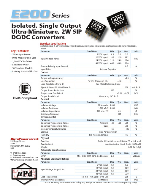
Key Features:• 2W Output Power • Ultra-Miniature SIP Case • 1,000 VDC Isolation • >2 MHour MTBF • 18 Standard Models •Industry Standard Pin-OutE200Isolated, Single OutputUltra-Miniature, 2W SIPDC/DC Conv ert e rsSeriesMicroPower Direct 292 Page Street Suite DStoughton, MA 02072USAT: (781) 344-8226F: (781) 344-8481E: sales@ W: Electrical Specifi cationsSpecifi cations typical @ +25°C, nominal input voltage & rated output current, unless otherwise noted. Specifi cations subject to change without notice.InputParameterConditionsMin.Typ.Max.UnitsInput Voltage Range5 VDC Input4.55.0 5.5VDC12 VDC Input 10.812.013.224 VDC Input 21.624.026.448 VDC Input44.048.052.0Reverse Polarity Input Current 0.3A Input FilterInternal CapacitorOutputParameterConditionsMin.Typ.Max.Units Output Voltage Accuracy ±3.0%Line RegulationFor Vin Change of 1%±1.2%Load Regulation (Note 1)See Model Selection GuideRipple & Noise (20 MHz) (Note 2)100mV P - P Output Power Protection 120%Temperature Coeffi cient ±0.01±0.02%/ºCOutput Short CircuitMomentary (0.5 Sec.)GeneralParameterConditionsMin.Typ.Max.Units Isolation Voltage 60 Seconds 1,000VDC Isolation Resistance 1,000 VDC 1,000M ΩIsolation Capacitance 100 kHz, 1V60pF Switching Frequency125kHz EnvironmentalParameterConditionsMin.Typ.Max.Units Operating Temperature Range Ambient-40+25+85ºC Operating Temperature Range Case+90ºC Storage Temperature Range -55+125ºCCooling Free Air ConvectionHumidityRH, Non-condensing95%PhysicalCase Size 0.46 x 0.29 x 0.40 Inches (11.68 x 7.5 x 10.2 mm)Case MaterialNon-Conductive Black Plastic (UL94-V0)Weight0.06 Oz (1.8g)Reliability Specifi cationsParameter ConditionsMin.Typ.Max.Units MTBFMIL HDBK 217F , 25ºC, Gnd Benign2.0MHours Absolute Maximum RatingsParameterConditionsMin.Typ.Max.UnitsInput Voltage Surge (1 Sec) 5 VDC Input -0.79.0VDC12 VDC Input -0.718.024 VDC Input -0.730.048 VDC Input-0.755.0Lead Temperature 1.5 mm From Case For 10 Sec260ºC Internal Power DissipationAll Models650mWCaution: Exceeding Absolute Maximum Ratings may damage the module. These are not continuous operating ratings.RoHS CompliantNotes:1. Output load regulation is specifi ed for a load change of 20% to 100%.2. When measuring output ripple, it is recommended that an external 0.33 µF ceramic capacitor be placed from the +Vout pin to the -Vout pin.3. O peration at no-load will not damage these units. However, they may not meet all specifi cations.4. The 5V, 12V and 24V input units do not require external components to operate, but the use of a low ESR capacitor (approximately 10 µF , ESR <1.0Ω at 100 kHz) mounted close to the converter input pins is recom-mended.For 48 VDC input units, an input capacitor should always be used. Depen-dent upon the application, a value between 4.7 µF and 47 µF should be suffi cient.5. Out put capacitive load capability of these units is 33 µF max. Exceeding this may cause start up problems.5. It is recommended that a fuse be used on the input of a power supply for protection. See the table above for the correct rating.Model Selection GuideNotes:• All dimensions are typical in inches (mm)• Tolerance x.xx = ±0.01 (±0.25)• Pin 1 is marked by a “dot” or indentation on the side of the unitMechanical DimensionsPin Description1-Vin 2+Vin 3-Vout 4+VoutPin ConnectionsModel Number InputOutput LoadRegulation(% Max)Effi ciency(%, Typ)Fuse Rating Slow-Blow (mA)Voltage (VDC)Current (mA)Voltage (VDC)Current (mA, Max)Current (mA, Min)Nominal RangeFull-Load No-LoadE2015 4.5 - 5.537238 3.3400.040.012711,000E2025 4.5 - 5.553338 5.0400.040.012751,000E2035 4.5 - 5.5500389.0222.022.08791,000E2045 4.5 - 5.55003812.0167.016.08801,000E2055 4.5 - 5.55003815.0133.013.08801,000E2111210.8 - 13.215030 3.3400.040.0873500E2121210.8 - 13.220030 5.0400.040.0877500E2131210.8 - 13.2211309.0222.022.0879500E2141210.8 - 13.21992512.0167.016.0884500E2151210.8 - 13.22082515.0133.013.0880500E2222421.6 - 26.410712 5.0400.040.0878200E2232421.6 - 26.4102129.0222.022.0882200E2242421.6 - 26.41041212.0167.016.0880200E2252421.6 - 26.41021215.0133.013.0882200E2324844.0 - 52.0536 5.0400.040.0878100E2334844.0 - 52.05269.0222.022.0880100E2344844.0 - 52.053612.0167.016.0878100E2354844.0 - 52.052615.0133.013.0880100MicroPower Direct292 Page Street Ste D Stoughton, MA 02072 • TEL: (781) 344-8226 • FAX: (781) 344-8481 • E-Mail: sales@Derating Curve。
最新201不锈钢板简介
●201不锈钢板简介:中国标准(GB)-牌号:1Cr17Mn6Ni5N ,201不锈钢板联众牌号LH低镍L1高镍L4(202不锈钢板,宝钢BN1(201不锈钢板,BN4(202不锈钢板),通过Mn,N元素替代Ni元素开发的200系列奥氏体不锈钢。
该钢种具有较好的耐蚀性和冷热加工性能,替代室内、内陆城市室外等腐蚀性不高的环境使用的304制品。
,主要有以下几种200系钢种:J1,J3,J4,201,202。
后来又出现了对镍含量控制更低的200等钢种,至于201C,就是在这后期中国个别钢厂研发的201的引申钢种,201的国家标准牌号是:1Cr17Mn6Ni5N,201C在201的基础上继续减少镍的含量,增加锰的含量。
201不锈钢板的定义:200 系列Cr—Mn 不锈钢镍价的波动促使许多的生产商寻求另一种与AISI304 性能相同的奥氏体不锈钢替代产品。
在20 世纪30 年代初,生产出了最初的铬锰(Cr—Mn)奥氏体不锈钢,钢中锰元素取代了部分镍。
此后,对具体的成分比例进行了更多的研究,使用了氮(N)和铜(Cu),控制强烈影响材料性能的元素碳(C)和硫(S)。
200 系列不锈钢的应用在印度所以成功,是由于在一些特定的用途中有可能替代304 不锈钢,而且没有危险。
与此相反,在其他地方,在市场上售处的200 系列不锈钢几乎没有控制硫、碳含量、存在着损害终端用户和不锈钢形象的风险。
●201不锈钢板用途:201不锈钢材、具有耐酸、耐碱,密度高、抛光无气泡、无针孔等特点,是生产各种表壳、表带底盖优质材料等。
主要用于做装饰管,工业管,一些浅拉伸的制品.●201不锈钢板性能:抗拉强度:100,000 to 180,000 psi 屈服强度:50,000 to 150,000 psi 伸长率:55 to 60% 弹性模量:29,000,000 psi 密度:.280lbs/cubic inch(密度7.93g/cm3)●201不锈钢板化学成分:201不锈钢板的元素锰(和氮)取代部分或全部镍有可能生产更低镍含量达不到平衡而形成了铁素体,为此,200 系列不锈钢中的铬铁含量降到15%-16%,某些情况下降到了13%-14%,其耐腐蚀性是不能与304和其他类似的钢比的。
PHCN-201 小型工业pH控制器说明书

Mini regulador de pH de montaje sobre panel de la línea de instrumentación y dispositivosEl PHCN-201 es un regulador de pH fácil de operar especialmente diseñado para aplicaciones donde el espacio o el coste son de gran importancia. Gracias a su tamaño compacto de solo 8 x 5 cm (3 x 2"), el PHCN-201 puede montarse en espacios reducidos y junto a tanques o cubas. El bajo coste del medidor también hace posible el control automático de procesos que hasta el momento solo se mantenían de forma manual, lo que supone un ahorro significativo de tiempo y dinero. Las medidas aparecen en grandes dígitos en el LCD y las luces LED indican el estado exacto del regulador, incluso a distancia. El PHCN-201 también dispone de un relé bidireccional. A través de un sencillo caballete de conexión al dorso del medidor, el operador puede seleccionar la dosificación ácida, lo que significa que el relé se activa con mediciones superiores al punto de referencia, o la dosificación alcalina, con el relé cerrado cuando se realizan mediciones por debajo del punto de referencia. Para ajustar el punto de referencia de pH 0 a 14 o calibrar el medidor en cualquier punto de la escala, simplemente accione el compensador correspondiente directamente en el panel frontal. El regulador es fácil de usar e instalar. Cualquier combinación de electrodo de pH con un conector BNC puede acoplarse al medidor. Hay tres modelos de medidores disponibles para una mejor adaptación a su aplicación. Puede elegir el modelo de 100 a 110 V o el modelo de 220 a 240 V . Para quienes prefieran trabajar a baja tensión, existe la versión de 12 Vcc, que incluye el transformador en el bajo coste del medidor.Especificaciones Rango: pH 0,0 a 14,0Resolución: pH 0,1Precisión (@ 20 °C/68 °F): pH ±0,2Calibración: Ajustable a 1 punto con compensador Punto de referencia: Ajustable de pH 0,0 a 14,0 con compensador Control de relé: 2 amperios @ 220 Vca Dosificación alcalina o ácida seleccionable Ácida: Se activa cuando la lectura es superior al punto de referencia Alcalina: Se activa cuando la lectura es inferior al punto de referencia Alimentación: 110/115 V; 50 a 60 Hz 12 Vcc externa (opcional) 220/240 V; 50 a 60 Hz (opcional)Entorno: de 0 a 50 °C (de 32 a 122 °F); HR máx. del 95%Dimensiones: 79 x 49 x 95 mm (3,1 x 1,9 x 3,7")Peso: 150 g (5,3 onzas)PHCN-201U seleccionable por el usuario U Calibración simple de un puntoU Tamaño reducido para facilitar la instalaciónU Elija entre los modelos de 100 a 240 V o de 12 Vcc de baja tensión U Práctico y cómodo El electrodo de pH PHE-1411, que se vende por separado, se muestra en un tamaño inferior al pleto de serie con manual del operador Añada “-12VCC ” o “-240VCA ” para requisitos opcionales de alimentación, sin cargo adicional.Ejemplo de pedido: PHCN-201, regulador de pH, PHE-7351-15,electrodo de pH, PHA-4, solución tampón 4,01, PHA-7, solución tampón 7,01.D-26I NSTRUMENTACIÓN Y D ISPOSITIVOS E LECTRÓNICOS D E pH I NDUSTRIAL。
UIT-201照度仪操作说明书
UIT-201照度仪操作说明书操作说明书感谢您这次购买UIT-201紫外线照度计,本说明书是对UIT-201紫外线照度计的概要、操作方法、规格等进行介绍的。
为了能够随时翻阅本操作说明书请妥善保管。
作为操作说明书的辅助资料,敝公司特意准备了《光测量指南》,有关详细内容请咨询敝公司的销售部门。
操作注意在操作注意中,记述了为安全正确使用本产品必须遵守的内容和需要注意的内容,请充分理解其含义之后再阅读正文。
!警告此表示是指我们预想的一些内容会导致人员伤亡。
!注意此表示是指我们预想的一些内容会发生人员伤害或测量仪损坏。
!重要在此表示中,记载了操作·维修保养时必须事先掌握的一些测量仪性能和容易发生错误操作的内容,以及不遵守说明规定、不校正测量仪的话会损伤测量仪的事项。
!警告请必须阅读下述警告事项之后再使用测量仪●从紫外线照射装置泄露出的光在短时间内可灼伤眼睛和皮肤。
在光泄露的地方测量时请配带保护眼镜,不要使皮肤裸露在外。
以下是保护眼睛的保护用具。
·保护眼镜:RS-24U (SPL3~5)理研镜片·保护面具:防紫外线面具(图号2046-1981)屋西奥电机!注意请必须阅读下述注意事项之后再使用测量仪●感光器是由光学部件构成的,请注意使用环境(温度·适度)。
特别是光学滤光片,它只能在规定的温度·湿度环境下发挥其性能。
在超出规定的环境下工作时,就不能发挥其应有的性能,有可能导致元器件老化。
请保管在可以管理温度湿度的干燥地方。
●禁止碰撞UIT-201主体以及感光器。
测量仪受到碰撞会导致内部元器件发生破损或引起不良动作。
●请使用酒精祛除UIT-201主体污垢。
请不要使用信纳水(香蕉水)、丙酮等有机溶剂擦拭本机,会损伤机器外观。
●请不要使用敝公司指定以外的感光器。
!重要请必须阅读下述重要事项之后再使用测量仪●本照度计测量范围虽然到1999,但在光强的情况下有时会导致感光器线性变坏。
GOTs 中文标准
全球有机纺织品标准国际工作组全球有机纺织品标准版本:1.1目录1 原则 (3)1.1 本标准的目的 (3)1.2 范围与结构 (3)1.3 版本 (3)1.4 标识等级 (3)2 要求 (4)2.1 有机纤维生产方面的要求 (4)2.2 材料成分方面的要求 (4)2.2.1 作为“有机”或“有机转化”产品来销售、贴标或展示的产品 (4)2.2.2 作为“有机材料含量为x%的产品”或“有机转化材料含量为x%的产品”来销售、贴标或展示的产品 (4)2.3 加工方面的要求 (5)2.3.1 分隔与识别 (5)2.3.2 在各个生产阶段都禁用/限用的材料 (5)2.3.3 各加工阶段助剂和染料方面的基本要求 (6)2.3.4 纺纱 (7)2.3.5 浆纱与编织/针织 (7)2.3.6 无纺生产工艺 (7)2.3.7 预处理阶段与湿加工 (7)2.3.8 染色 (8)2.3.9 印花 (8)2.3.10 整理 (8)2.3.11 辅料方面的要求 (9)2.3.12 环境管理 (10)2.3.13 废水处理 (10)2.3.14 贮存、包装与运输 (10)2.3.15 记录保存与内部质量保证 (11)2.3.16 技术特性参数 (11)2.3.17 有机纺织品中的残留物参照值 (12)2.3.18 其它材料与辅料中的残留物参照值 (13)3 最低程度社会要求 (15)3.1 范围 (15)3.2 工作应当可以自由选择 (15)3.3 结社的自由和集体谈判的权利应当受到尊重 (15)3.4 工作环境应当安全而卫生 (15)3.5 不得使用童工 (16)3.6 应当支付最低工资 (16)3.7 工作时间不得超标 (16)3.8 不允许有歧视 (17)3.9 必须提供正式雇用 (17)3.10 不允许有粗暴或不人道对待 (17)4 质量保证体系 (18)4.1 加工与生产阶段的检查 (18)4.2 残留物试验 (18)附件 (19)其它纤维 (19)缩略词 (19)1 原则1.1 本标准的目的本标准旨在定义确保纺织品有机状态方面的要求,包括:原材料的收割、对环境和社会负责的生产、以及标识,以确保让终端消费者放心。
X1NiCrMoCu25-20-5替代牌号X1NiCrMoCu25-20-5硬度
X1NiCrMoCu25-20-5替代牌号X1NiCrMoCu25-20-5硬度一:牌号:X1NiCrMoCu25-20-5奥氏体不锈钢二:化学成分:碳C:≤0.02锰Mn:≤2.00硅Si:≤1.00铬Cr:19.0~23.0 镍 Ni:23.0~28.0磷 P:≤0.045硫 S:≤0.035钼 Mo:4.0~5.0 铜 Cu:1.0~2.0 三:应用范围应用领域:常年现货库存圆棒板材无缝管卷带!石油、石化设备,如石化设备中的反应器等,硫酸的储存与运输设备,如热交换器等,发电厂烟气脱硫装置,主要使用部位有:吸收塔的塔体、烟道、档门板、内件、喷淋系统等,有机酸处理系统中的洗涤器和风扇,海水处理装置,海水热交换器,造纸工业设备,硫酸、硝酸设备,制酸、制药工业及其他化工设备、压力容器,食品设备,制药厂:离心机,反应器等,植物食品:酱油罐,料酒,盐罐,设备和敷料,对稀硫酸强腐蚀介质904L是匹配的钢种。
四:物理性能:密度:8.24g/cm3。
抗拉强度:σb≥520Mpa。
延伸率:δ≥35%。
五:概况此钢热成型可在1000--1150摄氏度进行。
该钢的热处理工艺为1100--1150摄氏度,加热后快冷。
此钢虽可采用通用的焊接工艺进行焊接,但是zui恰当的焊接方法是手工电弧焊和钨极氩弧焊。
当采用手工电弧焊焊接不大于6毫米板材时焊条直径不大于2.5毫米;当板厚大于6毫米时焊条直径小于3.2毫米。
当焊后需热处理时,可以在1075--1125摄氏度加热后快冷进行处理。
用钨极氩弧焊焊接时的填充金属可用同材焊条,焊后焊缝须经酸洗,钝化处理。
铬(Cr):在结构钢和工具钢中,铬能显著提高强度、硬度和耐磨性,但同时降低塑性和韧性。
铬又能提高钢的抗氧化性和耐腐蚀性,因而是不锈钢,耐热钢的重要合金元素。
7、镍(Ni):镍能提高钢的强度,而又保持良好的塑性和韧性。
镍对酸碱有较高的耐腐蚀能力,在高温下有防锈和耐热能力。
但由于镍是较稀缺的资源,故应尽量采用其他合金元素代用镍铬钢。
- 1、下载文档前请自行甄别文档内容的完整性,平台不提供额外的编辑、内容补充、找答案等附加服务。
- 2、"仅部分预览"的文档,不可在线预览部分如存在完整性等问题,可反馈申请退款(可完整预览的文档不适用该条件!)。
- 3、如文档侵犯您的权益,请联系客服反馈,我们会尽快为您处理(人工客服工作时间:9:00-18:30)。
12 1-800-735-6200
70
Converter Selection Chart
VI-2
Mechanical Drawing
Features
s Up to 50W/Cubic Inch
s UL, CSA, TÜV, VDE, BABT, AUSTEL
s Up to 90% Efficiency s Size: 4.6" x 2.4" x 0.5"(116,8 x 61,0 x 12,7)
s Remote Sense and Current Limit s OVP, Thermal Shutdown s Logic Disable
s Wide Range Output Adjust
s Compatible Power Booster Modules s ZCS Power Architecture s Low Noise FM Control s CE Marked
VI-200
DC-DC Converters 50 to 200 Watts
Product Highlights
The VI-200 Family, with over 8 million
shipped, is Vicor’s first generation of
“zero-current-switching” component-level DC-DC converters.
Operating at frequencies up to 2 MHz, VI-200 Family Converters offer
exceptional power density, efficiency,noise performance, reliability and ease of use. Power Boosters provide a simple, cost effective, off-the-shelf solution for higher power output requirements. One or more boosters may be used to create synchronous arrays capable of supplying several kilowatts of output power.
The flexibility of Vicor’s power components is also available in half-size, half-power VI-J00 MiniMods. (pg. 72)
Packaging Options
SlimMods™, high power density,
flangeless packages and FinMods™,featuring integral finned heatsinks.SlimMod: Option suffix: - S Example: VI - 2XX - XX - S
FinMod: Option suffix: - F1and - F2Examples:
VI - 2XX - XX -F1, 0.75" height VI - 2XX - XX -F2, 1.00" height
Max. Output For 5V Outputs > 5V Outputs
< 5V Outputs
(1)75W 75W 15A (2)150W 150W 30A (3)
100W
100W
20A
* Brownout 75% of rated load; transient voltage for 1 second.
Max. Output For 5V Outputs > 5V Outputs < 5V Outputs
(4)200W 200W 40A (5)150W 200W 40A (6)
75W
100W
20A
Rev 3 1 of 2
For the latest Vicor Product Information:
12 1-800-735-6200
71
VI-200 E-Grade
VI-200 C-, I-, M-Grade PARAMETER
MIN.TYP.MAX.
MIN.
TYP.
MAX.
UNITS
TEST CONDITIONS
s Input Characteristics Inrush charge
120x10-6120x10-6200x10-6Coulombs
Nominal line
Input reflected ripple current – pp 10%
10%
I IN
Nominal line, full load Input ripple rejection
dB 120 Hz, nominal line dB 2400 Hz, nominal line
No load power dissipation 1.352
1.352
Watts
s Output Characteristics Setpoint accuracy 1%
2%0.5%1%V NOM Load/line regulation 0.5%0.05%0.2%V NOM LL to HL, 10% to Full Load Load/line regulation 1%
0.2%0.5%V NOM LL to HL, No Load to 10%Output temperature drift 0.020.010.02
% / °C Over rated temp.
Long term drift 0.02
0.02%/1K hours
Output ripple - pp: 2V, 3.3V 150 mV 60 mV 100 mV 20 MHz bandwidth 5V 5%2%3%20 MHz bandwidth 10-48V 3%0.75%
1.5%20 MHz bandwidth Trim range 1
50%110%
50%110%Total remote sense compensation 0.5
0.5Volts 0.25V max. neg. leg OVP set point 125%2
115%125%2
135%V NOM Recycle power Current limit
105%135%105%125%I NOM Automatic restart
Short circuit current 320%
140%
20%
130%
I NOM
s Control Pin Characteristics Gate out impedance 5050Ohms Gate in impedance
103103Ohms Gate in open circuit voltage 6
6
Volts Use open collector
Gate in low threshold 0.650.65Volts Gate in low current 66mA
Power sharing accuracy 0.95
1.05
0.95
1.05
s Dielectric Withstand Characteristics Input to output 3,0003,000V RMS Baseplate earthed
Output to baseplate 500500V RMS Input to baseplate 1,5001,500
V RMS
s Thermal Characteristics Efficiency
78-88%80-90%Baseplate to sink 0.20.2°C/Watt With Vicor P/N 01777Thermal shutdown 490
95
10590
95
105
°C
Cool and recycle power (Drivers only)to restart
s Mechanical Specifications Weight
6.0 (170) 6.0 (170)Ounces (Grams)
110V, 12V and 15V outputs, standard trim range ±10%. Consult factory for wider trim range. 2
131% nominal for booster modules.
3Output voltages of 3.3V or 5V incorporate foldback current limiting; all other outputs provide constant current limiting.4No overtemp protection in booster modules.
Converter Specifications
(typical at T BP =25°C, nominal line and 75% load, unless otherwise specified)
25+20Log ( Vin
)
Vout
30+20Log ( Vin
)Vout
20+20Log ( Vin
)
Rev 3 2 of 2
For the latest Vicor Product Information: 。