A Simulation Framework for Combustion, Burning, and Decomposition of Solid Objects
专业英语--产品介绍
c.Press the INV key and you can raise the constant e (2.7182818) to x powers.
(4)选择合适的翻译技巧遣词造句,重述原文内容; a. Internet is of great help to our work. b.Mankind has always reverenced what Tennyson call “the useful trouble of the rain”.
4)后置定语很常见; The connecting rod, in essence, is a bar or strut with a bearing at each end, whose purpose is to transmit the piston thrust to the crankshaft. 5)名词连用 a. computer programming teaching device manual
What are the chances of a nuclear war in the near future? How many Americans would survive a nuclear attack? Would such an attack make living conditions impossible for the survivors? These and similar questions are being asked by citizens groups throughout this country as they debate the issue of arms control and nuclear disarmament.
流体网络法用于微型燃烧室的一维计算

乙.
K. .=/ . i,
(7)
i,丿’/
式中
屁,f 64
—,Re W 2 300
f=I
(8)
(中沁[瓦 ]}) / (
[6.9 泸/d 1.11 ] ] \2
[
+(I7) ,fie>2 300
1.2燃烧室沿程热力计算
a)环腔通道热力参数计算 取第i截面至i+1截面之间为控制体,如图2[7]所示。对 于该控制体,建立连续方程、状态方程、能量方程和动量方程, 从已知的扩压器出口截面一直计算到燃烧室出口截面。
C - 4 B )( %i& an , i+1
P, i+| = 4 v
an , i+1 an,i+1
静温:
歹
=, i+|
聞,屮二 RPan , i+1
(18) (19) (20)
b)火焰筒沿程热力参数计算
根据当地余气系数,采用多项式计算火焰筒内沿程
总温:
T=4|+42a+43a2+44a
S;J为-1;p*为两端节点(节点i和节点j)密度的算术平均
值,即Pi j = (P; +Pj) /2,由理想气体状态方程得= p*/。
由此方程中仅q;“仍是未知量,需依据动量方程建立体积
流量与压降的关系式[3]o
p p Pl;, = Lj - Li = 0,用;“
丄+叵(J L 仏=Si,#,"
2 ,42,
, .
沖
i+1
A B %i+| %a ]
1
2 4an
B 1- 4 +4 2 =
CR -
Fluid-Structure Interaction
Fluid-Structure Interaction Fluid-structure interaction (FSI) is a complex and fascinating phenomenon that occurs when fluid flow interacts with solid structures, resulting in mutual influence and dynamic behavior. This interdisciplinary field has significant implications in various engineering applications, including aerospace, civil engineering, biomechanics, and offshore structures. Understanding FSI is crucialfor optimizing the performance, safety, and reliability of these systems. In this response, we will explore the challenges, implications, and advancements in FSI, considering both the fluid dynamics and structural mechanics perspectives. From a fluid dynamics standpoint, FSI presents intricate challenges due to the nonlinear and coupled nature of fluid-structure interactions. The behavior of the fluid is influenced by the motion and deformation of the solid structure, while the solid structure experiences forces and pressures exerted by the surrounding fluid. This bidirectional interaction leads to complex phenomena such as vortex shedding,flow-induced vibrations, and instabilities, which can have detrimental effects on the structural integrity and performance of engineering systems. Furthermore, the inherent complexities of turbulence, compressibility, and multiphase flow add another layer of intricacy to FSI problems, necessitating advanced computational and experimental techniques for accurate analysis and prediction. On the other hand, from a structural mechanics perspective, FSI introduces challenges relatedto dynamic response, fatigue, and failure analysis of the solid components. The interaction with the surrounding fluid can induce dynamic loading, resonance, and fatigue cycles, leading to structural degradation and potential failure. Moreover, the fluid-induced forces can result in complex structural deformation and stresses, requiring comprehensive modeling and simulation approaches to assess thestructural response under varying operating conditions. In the context of offshore structures, for instance, FSI plays a critical role in the design and maintenance of platforms, considering the impact of waves, currents, and wind on thestructural integrity and stability. In recent years, significant advancements have been made in the computational modeling and simulation of FSI, leveraginghigh-fidelity numerical methods and advanced algorithms. Computational fluid dynamics (CFD) and finite element analysis (FEA) techniques have been integratedto simulate the coupled behavior of fluids and structures, enabling engineers to gain insights into the complex interactions and their implications. Furthermore, the development of multiphysics simulation platforms and software tools has provided a comprehensive framework for studying FSI problems across different engineering domains, facilitating the design optimization and performance assessment of various systems. In addition to computational approaches, experimental techniques such as wind tunnel testing, water flume experiments, and structural testing have been instrumental in validating FSI models and understanding the physical phenomena associated with fluid-structure interactions. These experimental investigations have provided valuable data for benchmarking simulations, validating theoretical models, and capturing real-world FSI effects that may not be fully captured through numerical analyses alone. From an emotional perspective, the challenges and advancements in FSI evoke a sense of awe and inspiration, as engineers and researchers strive to unravel the complexities of nature and develop innovative solutions to enhance the performance and safety of engineering systems. The interdisciplinary nature of FSI fosters collaboration and knowledge exchange across fluid dynamics, structural mechanics, and materials science, creating a vibrant community dedicated to pushing the boundaries of understanding and application in this field. In conclusion, fluid-structure interaction represents a captivating and multifaceted area of study with profound implications for engineering design, analysis, and optimization. The challenges and advancements in FSI underscore the intricate interplay between fluid dynamics and structural mechanics, driving the development of advanced computational and experimental techniques to unravel the complexities of this phenomenon. As we continue to explore and innovate in the realm of FSI, we are poised to unlock new possibilities for enhancing the performance, reliability, and safety of engineering systems across diverse applications.。
一个开源免费的系统级网络仿真平台框架EuroSimSimulationFramework
EuroSim Simulation FrameworkR.H. de VriesDutch Space B.V., P.O. Box 32070, 2303 DB Leiden, The Netherlands************************AbstractThis paper describes the concepts and features of EuroSim. Recent and future additions receive special attention, such as the redesigned Graphical User Interface and the port to the Windows platform.1. IntroductionOriginally developed as a simulator-framework on IRIX for Real-Time-purposes, the EuroSim consortium - Atos Origin, Dutch Space and NLR – has recently released its Mk3-version. This new release has a significantly improved Graphical User Interface, based on an extensive Human Computer Interface study. During this upgrade, also a Windows-based version was developed, completing the earlier released IRIX- & Linux-versions. EuroSim is a versatile simulation tool which can be used in all phases of the development of spacecraft. It can be used from the feasibility stage up to operations. It is especially useful during testing as it has extensive support for hardware-in-the-loop real-time simulations. It supports models written in C, C++, FORTRAN 77 and ADA, hardware interfaces such as MIL1553, IRIG-B, GPIB, Reflective Memory, etc., configuration control systems like CVS, and much more.Most of our customers start modelling in MATLAB/Simulink, commonly used in engineering companies and universities. Since 1999 it is possible to transfer MATLAB/Simulink models to EuroSim with MOSAIC. MOSAIC automatically converts model source code that has been generated with the Real Time Workshop (RTW) of MATLAB into model source that can be incorporated in EuroSim, where additional EuroSim specific files are also created automatically. While further detailing and expanding models, long execution times and other barriers are encountered. At that moment, EuroSim helps in a growing path to further enhancements.2. Multi-platform availability increases application in the full project lifecycleWith the port of EuroSim to the Windows and Linux (Real-Time) operating systems a large leap towards application of EuroSim in the full project life cycle has been made. The port of EuroSim to the various operating systems has been done in such a way that for a EuroSim simulation developer the environment looks the same and has basically the same functionality. This specifically holds for the way the various software simulation tasks are treated during scheduling. This is important, since it causes the simulation engineer early in the project to already adhere to the basic rules that real-time simulation poses in later phases of the project. So by using EuroSim already in the earliest phases of a project, e.g.feasibility studies, later on a smooth transition can be made towards system engineering and operations simulations, in which real-time constraints appear. Since the EuroSim simulation code base can be reused between the various project phases, the total cost of ownership decreases, project-planning risks decrease and shorter schedules are possible. With EuroSim being available on various platforms, several growth paths appear. One can, for example, start developing EuroSim simulations on the Windows desktops and later on transit smoothly to the PC-based Linux-version, when multi-processing, Real-Time-performance and common hardware I/F’s are required. From there the next step can be to switch to dedicated hardware using the IRIX-version. The latter is especially useful where real-time operation (frequencies up to 1000 Hz) and highly demanding visualizations come into play (e.g. training-simulators).So with the availability of EuroSim on diverse platforms the at least following benefits for the customer are created:•During all phases, the same models can be employed, greatly reducing the effort of reprogramming earlier (auto-generated) code for Real-Time purposes and Hardware-In-The-Loop testing.•Since EuroSim fully (and actively) supports ESA’s SMP-standard, the continued use of C++ models generated from UML by e.g. Rational Rose or Software through Pictures is ensured.•All supported platforms share the same GUI design and all files can be re-used, converted or re-built when moving to another platform.•Procurement of (costly) dedicated hardware can be postponed till all requirements are known and frozen.3. EuroSim conceptEuroSim is based on the principle that each simulator can naturally be broken down into an invariant tool part and a part that is specific to the subject being simulated: the latter is called the (simulation) model. The model is a software representation of the behavior of a particular real-world system. By means of a careful design of the tool part, it can be used for both small and large simulators, and it can support the portability of simulation models, allowing them to be re-used between projects and to exchange one model for another, e.g. one offering higher fidelity. Having such a tool available will help to reduce the cost associated with simulation and/or allow it to be used more extensively and earlier in a Space project. It will also help to concentrate the effort on model development itself, i.e. the project specific part of the simulation.Figure 1: EuroSim work flowThe model editor is used to define the simulator executable and data dictionary. In the schedule editor the user configures the execution order of the functions. The simulation controller is used to define and run simulations. The test analyzer allows easy creation of plots for analysis purposes. The project manager is used to manage a database of projects and project files, and is used to start the individual tools.4. Graphical User InterfaceEuroSim runs on various platforms, IRIX, Linux, Windows NT/XP. This requires a toolkit that is portable, fast and programmer friendly. The obvious choice is the Qt toolkit from Trolltech. This toolkit has proven itself as the basis of the highly successful KDE desktop environment under Linux. The toolkit has also support for various GUI styles, so that the application looks exactly like the native applications, but can also have the same look as another platform. If the user wants to have a Windows look and feel under Linux, that is no problem.The Project Manager tool provides an overview of all files used in a simulation project.These files can be opened directly from the project file overview.Project ManagementModel Editor Schedule Editor Simulation Controller Test AnalyzerModelFigure 2: EuroSim Project ManagerThe model editor allows the simulator developer to integrate models into the EuroSim infrastructure. The developer selects the variables and functions to be published into the data dictionary. The data dictionary is used in all tools to gain access to the simulation data. The model editor is also responsible for the creation of a simulator executable.The user can add information to the elements which are placed in the data dictionary. Forvariables it is possible to define the unit, minimum and maximum values and a description.Figure 3: EuroSim Model EditorThe Schedule Editor is used to define the execution order of the functions published in the data dictionary. The editor allows parallel execution and many more primitives, providing fine grained control over the run-time behavior of the simulator. This enables users to fine-tune the execution timing for real-time applications.When the user is not interested in real-time scheduling a few simple tasks (maybe parallel) are enough to define a schedule. The schedule can then be executed in as-fast-as-possible mode. This mode executes the model software as fast as possible with very little overhead of the system. The user can still record data from the simulator at the specifiedfrequency for later analysis.Figure 4: EuroSim Schedule EditorThe Simulation Controller tool is the GUI to control the execution of simulators. The tool can define scripts, initial conditions and displays. Scripts form the building blocks of scenarios. The scripting language allows users to inject errors in simulation, trigger actions, record data etc. Display screens are called MMI (Man-Machine Interface) screens. An MMI screen can hold multiple monitors. The layout of each screen can be customized by the user to suit his needs. As a simulation configuration can hold many MMI screens it is very easy to create one screen for each purpose. Each screen is placed under a separate tab to allow easy switching between views. It is not needed to create a new monitor if you just want to have a quick look at one variable. The API tab page shows the entire data dictionary tree of the simulator with the values of each variable. The data isupdated at the usual frequency of 2 Hz. It is also possible to change values there.Figure 5: EuroSim Simulation ControllerThe Test Analyzer tool allows the user to produces plots of recorded data. A wizard guides the user through the process of producing a plot. As the tool is fully integrated into the EuroSim environment, it is very easy to create plots using the variables in the recorderfiles. The plots can be shown on screen, printed, or written to file for use in documents.Figure 6: EuroSim Test Analyzer5. External InterfacesAn important aspect of almost any system is the way it can interface and cooperate with other systems. This section discusses EuroSim’s on-line interfaces. A number of them are available. First, EuroSim offers support – through the EuroSim library – for a number of ‘physical’ or hardware interfaces: serial RS232/422, VME, IRIG-B, Reflective Memory, GPIB, external interrupts and the MIL1553B data bus (both as bus controller or remote terminal). These hardware interfaces make it possible to build mixed hardware/software simulations. Early in a project’s life cycle, the simulation will be fully software based. In later stages, when (breadboards of) hardware units become available, software sub-models can be replaced by this actual hardware. This will then allow the testing of this hardware in a closed loop manner and it will increase the fidelity of the simulation itself. Secondly, EuroSim offers an important ‘software’ interface that is called ExternalSimAccess. This interface allows the user – with remarkably little programming –to map some or all of EuroSim’s model data dictionary variables into the address space of his application. This application then effectively becomes a client to the EuroSim simulation server, and can – just as the standard EuroSim clients such as the SimulationController – be run either locally or remote. When run remotely, the connection between the server and the client is TCP/IP based. ExternalSimAccess makes it easy torealize a distributed application over a network, e.g. for multi-user simulations.By the mapping of data dictionary variables into the client’s address space, the client can simply read and write these variables as if they were local variables. Synchronization between the client and the server is achieved as follows. The client subscribes to the server and requests a view of some data dictionary items at a certain frequency, e.g. 20 Hz. The server – EuroSim – will then, until further notice, provide the client with the requested view at the requested frequency, synchronized with the frequency of the simulation process itself.This synchronization ensures consistent data views. The client will be notified of a new view ‘arriving’ by means of a signal or it can perform a (non-blocking) poll for new data. When new data is available, the client can start processing that data, and then runs effectively synchronized with the server. Alternatively, the client can run a-synchronously and, when needed, request the latest data view from a locally (at the client side) held queue. Locally modified data dictionary variables can be sent back to the server by means of a function call. This call will initiate the data transfer to the server, where it will be ‘injected’ into the data dictionary; this injection will occur synchronously with the simulation process. To minimize network bandwidth usage, data compression strategies are employed in ExternalSimAccess.EuroSim itself is using the ExternalSimAccess mechanism for the interface (back and forth) with the Image Generation System. This system is of course driven by the data from the simulation model, but can report back events like a collision occurring between two geometry objects.6. Batch ProcessingRunning EuroSim simulators using a GUI may be very user-friendly for the beginning user, but when certain simulation runs need to be repeated very often, a GUI is not the ideal method. When simulation runs need to be automated the user can use the EuroSim batch utility, which is implemented as a Perl module. The Perl scripting language is very powerful and many extension modules are available on the Internet. Among the available modules are all major SQL database interface modules, various network protocol modules, GUI modules, XML processing modules and many more (see for an exhaustive list of available modules). At first, the user can write simple scripts as shown in figure 9 and then enhance them to perform complicated tasks. Examples of applications are regression testing, Monte-Carlo runs and automatic unit testing.The batch utility implementation is object-oriented. The user creates a session object and performs all operations on that object. All methods are modelled after how the simulation controller works. EuroSim state change commands are modelled after the state change buttons on the Simulation Controller GUI. Users can create event-handlers to process events coming from the simulator. Scripts can be extended with freely available modules to interface with existing infrastructure. Using this method, users can integrate EuroSim into their environment leading to improved productivity.Figure 7: EuroSim perl script example.7. ConclusionThe EuroSim simulator framework offers many features which make it suitable for most simulation applications. Users can concentrate on developing model software, instead of developing the simulator infrastructure. Not only real-time simulators can be made, but also non-real-time ones, using the as-fast-as-possible feature. The flexibility of EuroSim allows users to re-use existing model software in EuroSim throughout all the phases of development. The investment in model software is protected. The EuroSim architecture scales from small machines to large multi-processor machines. EuroSim is now several years in use and is a proven platform. EuroSim is continuously enhanced to cover the needs of existing and new users.。
A Formal Model of a Framework for Simulation- Based Animation
A Formal Model of a Framework for Simulation-Based AnimationWolfgang Mueller, Volker PaelkeUniversity of Paderborn, C-LABFürstenallee 11, D-33102 Paderborn, Germany{wolfgang, vox}@c-lab.deAbstractWe present a rigorous formal - but transparent - specification of the semantics of a generic simulation-based 3D animation framework. Our system combines a SystemC simulation kernel with a virtual visualization machine for 3D animation. The semantics of the simulator and the virtual visualization machine are formally defined by means of distributed Abstract State Machine (ASMs) rules. The ASM rules truly reflect the specification given in the SystemC User’s Manual and additionally provide a comprehensive definition of the virtual machine for advanced 3D animation. For the interaction between the SystemC simulator and the visualization we have defined a simple message exchange protocol, which can be used for socket communication.We see our formal semantics as a concise, unambiguous, high–level documentation-oriented specification to capture the complex interaction between the SystemC simulator and the visualization and to define adequate interfaces.1 IntroductionAlthough visualization systems for both desktop 3D and virtual reality (VR) environments are in widespread use today, their execution models are usually only available as an informal description. Their concrete semantics is typically only defined by their implementation in programming languages like C or C++ or by the means of a UML specification. Even if the source code is available, it is difficult for developers toachieve a clear and correct understanding of an execution model that is implicitly defined by thousands of code lines. If a developer is not deeply familiar with the visualization system this typically leads to a try and error approach during development in order to explore the actual semantics of the execution model. While this approach may be acceptable for the development of stand-alone visualization applications, it becomes deeply problematic when the visualization must be integrated with other software components (e.g., simulators) into a coherent system for which a well defined semantics is required in order to make correct assertions about the behavior of the composite system.A similar requirement for a well-defined semantic specification of the execution model exists for the other system components. In this paper we discuss the integration of a SystemC simulator with a 3D animation system for visualization. SystemC was introduced by OSCI [5] for system level modelling and simulation for combined HW/SW systems. It follows in the line of domain-specific standard system design languages that have proliferated in system development, e.g., UML for SW design, SDL for telecom protocols, VHDL and Verilog for discrete HW systems.Since the complex simulation semantics of SystemC is not clearly outlined in the Standard user’s manual [5], we have defined a complete semantics description of the simulation kernel by means of ASMs (Abstract State Machines) in [2]. ASMs provide a concise definition of the complete SystemC V2.0 simulation semantics for precise documentation and give a clear formal semantics for synthesis and interoperability with other languages.In this paper, we exploit ASM semantics specifications of both the SystemC simulator and the visualization system to compose a well-defined framework for simulation-based animation of 3D models. Through this we can tightly couple the SystemC simulation kernel with the 3D animation so that the virtual 3D model is directly controlled by the model of the system rather than by a replacement of it in a third modelling/description language.ASMs were introduced by Gurevich [6] and have found wide-spread use since they provide a concise and rigorous but yet intuitive way to define system semantics. We have used the ASM framework to develop a mathematical definition of our system in terms of an Algebra describing the execution of the SystemC simulation kernel and the virtual visualisation machine for advanced 3D animation including their event based interaction and message exchange.The remainder of this article is organized as follows. In Section 2, we give basic information on what is needed from distributed ASMs. In Section 3, we introduce the simulation and visualization components and describe how they combine to a simulation-based 3D animation framework. Section 4 illustrates our approach with an example and Section 5 closes with a conclusion and an outlook on future work.2 Abstract State MachinesAbstract State Machines (ASMs) were introduced by Gurevich in [6]. They can be understood as ‘pseudocode over abstract data’, without any particular theoretical prerequisites. Here, we list only the basic definitions and refer to [6] for a formal introduction.An ASM specification comes in form of guarded function updates (rules). Rules are basically nested if–then–else clauses with a set of function updates in their body. When executing the rules, the underlying ASM abstract machine performs state transitions with algebras as states. Firing a set of rules in one step performs a state transition. Only those rules are fired whose guards (Conditions) evaluate to true. Rules are of formif Condition then <Updates>else <Updates>endifAt each step, guards evaluate to a set of function updates (block) each of form f(t1, …, t r), where t i are terms (including functions). Note here that 0-ary functions play the role of variables in imperative programming languages. A block is a set of function updates separated by a comma. The individual function updates of each block are collected in a so–called update set. The individual updates of the update set are simultaneously executed in one step. Each function update changes a value at a specific location given by the left–hand–side of the assignment where functions are considered to be global. Two or more simultaneous updates of the same location in one update set define inconsistency. In the case of an inconsistency no state transition is performed and no update in the update set is being executed. We demonstrate this by a simple example with a guarded update:if true then A:=B, B:=A endifThat definition gives a simultaneous update of the 0-ary functions A and B. Since both updates are simultaneously executed, A becomes the value of B and vice versa. The true condition in the guard fires the rule at each step.ASMs are multi–sorted based on the notion of universes. We assume the standard mathematic universes of booleans, integers, lists, etc. as well as the standard operations on them without further mentioning.The extension of basic ASMs to Distributed ASMs partitions rules into modules where each module is given by its module name v. A module is instantiated to execute by setting Mod(a) := v for an agent a. The symbol Self refers to a after the instantiation. The execution is defined by partially ordered state transitions where agents are asynchronously executed. However, though the SystemC specification is based on Distributed ASMs, the main section can be understood without their introduction. Therefore, we refer the interested reader to the complete specification given in [2].3 Simulation-Based AnimationIn our approach, we investigate the field of VR animation where object animations are triggered by events of an existing discrete event-based simulator. In contrast to other approaches where animated objects are controlled by a program for just one specific application, in our approach, the model under design directly controls visual objects. Thus, once that simulatable model is available, no additional implementation effort except for the definition of exchanged messages and their conversion into events and commands has to be undertaken. In order to provide a most generic approach, synchronisation is not performed with each individual object in the simulation model but instead by the event mechanism of the simulation kernel. Because interfacing a complex simulation is not that trivial so that we apply the formal means of Abstract States Machines for that purpose.In the next section, we first outline the general architecture of coupling a simulator with an advanced Virtual Reality Animation engine, the so-called Virtual Visualization Machine (VVM). Thereafter, we give details of the VVM, the simulator, and theirinteraction. As a representative for an event-based simulator we have selected the SystemC simulator since it covers general event-based simulation concepts including unit time delay processing. Additionally, since it is available as open source our concepts could be nicely verified by an implementation. We finally close this section describing the simulator-VVM interface and the messages, which are exchanged between animation and simulation.3.1 System OverviewOur system for simulation-based animation is composed of three main parts: interaction, visualization, and simulation (cf. Figure 1). The user interacts via input and output devices with the user interface of the 3D Virtual Reality environment. In addition to the 3D graphics rendering services usually given by a 3D toolkit, the visualization component also provides autonomous animation and interaction capabilities by the Virtual Visualization Machine (VVM). The basic principles of the VVM are inherited from the implementation of the I4D toolkit [6].Figure 1: General System ArchitectureThe VVM manages basic animation, i.e., transformation of VR object properties over time like location, size, and colour. This allows animating complex state changes in a perceptually pleasing way, e.g., by animating the motion of visualization objects along interpolated smooth paths even if only start and end position (or abstract states) are provided by the simulation. For that, the VVM also takes over the synchronization with the respective simulator by receiving and executing commands and sending events. Through the synchronization VR objects behave as true representations of the simulation objects. The communication between simulation and VVM is affected by means of the string based message exchange protocol that is outlined in Section 3.4. Using this communication interface, it is possible to connect several simulators1 to the VVM, each controlling separate or shared visualization entities within a common visualization environment. Messages sent to the simulator are transformed to events of the simulator. Messages sent to the VVM are received as VVM commands. In the following 1 Without the loss of generality just instances of a SystemC simulator are investigated. However, the presented concepts may apply to most event-based simulators as well.description, the first ones are given as ExternalEvents and the latter ones as ExternalCommands, where both are organized as FIFO buffers.3.2 The Virtual Visualization Machine (VVM)As given in Figure 2, the main VVM components are the runtime interpreter and the runtime data structure. The interpreter receives commands and sends events, manipulates the runtime data structure, and triggers the renderer. The runtime data structure is basically composed of hierarchically organized actors, which inherit properties from their parent. Actors may refer to abstract objects like group container or to concrete 3D objects with their properties as attributes. For advanced animation over time, actors schedule their methods as behaviors into a runtime queue (BEHAVIOR). All BEHAVIORs are executes by the runtime interpreter. They may modify ACTORs and recursively schedule new BEHAVIORs. Additionally, ACTORs refer to parts of the scene graph, which is rendered when being triggered by the runtime interpreter.Figure 2: VVM – Basic PrinciplesFor the coupling of the VR animation and the simulator, the VVM runtime interpreter receives commands and sends events through the buffers ExternalCommands and ExternalEvents. To give synchronization details, we outline the VVM interpretation cycle by means of formal ASM rules.Figure 3 shows the main VVM interpretation cycle with its individual steps on the left. On the right, the figure gives the corresponding sequential ASM steps until the interpretation is stopped where the individual steps are given as ASM macro definitions. Macros are placeholders for ASM rules in order to achieve a better readability of the ASM specification.Figure 3: VVM Runtime InterpreterIn the ASM definition, we follow a state-based definition of the individual steps where the individual states are represented by the function step , which is checked by each rule and finally set to the next corresponding state. After initialisation, the VVM first reads the next external command and assigns it as a currentCommand before executing it in the next step .In step executeCommand , the currentCommand is executed based on the given runtime data structures, i.e., the set of ACTORs and the sequence of BEHAVIORs. We specify that by the function executeCommand and leave details open for its implementation since they are not relevant for further synchronization concepts.Executing a command, may execute methods of ACTOR s, which are scheduled in the queue of BEHAVIORs. After its execution, when no other commands are available, aBEHAVIOR b is executed in the order as it was scheduled. Thus, if any, the first element of the BEHAVIOR queue becomes the currentBehavior and is removed thereafter.The next step executeBehavior , executes the currentBehavior based on runtime data structures (BEHAVIOR and ACTOR). This is also the point where the corresponding event of the currentBehavior , i.e., event(currentBehavior ), is scheduled to the buffer of ExternalEvents . Here, we leave open how to transform the currentBehavior to an event since it is specific to the individual implementation.If there are further objects scheduled, the interpreter reads and executes the next behavior until the queue of BEHAVIORs becomes empty.2 Thereafter, the next frame is rendered. For rendering, all ACTORs are processed starting from the root object. When an actor refers to a part of a scene graph, the corresponding scene graph objects are rendered.Finally, the interpreter advances to the next cycle and reads the next command. 2Note here, that the execution of a behavior may schedule a new behavior again.3.3 The Extended SystemC Simulation KernelThe SystemC language is defined as a C++ language extension by parallel PROCCESSes and events for the description and simulation of discrete hardware-oriented systems. The compiled executable realizes a cycle-based simulator that implements a set of parallel running SystemC PROCESSes communicating through so-called channels. Those (user defined) PROCESSes are scheduled by the SystemC simulation kernel. Executing PROCESSes suspend when executing a wait statement or after the processing of their last statement. Based on explicit events, implicit events (updates of channels), or expiring timeouts, processes may resume for execution. The SystemC simulation kernel manages events, channel updates, and the resumption of processes. Here, suspended processes do not immediately resume. They are first assigned as ‘ready to run’ before they resume.In the following, we take the SystemC ASM specification introduced in [2] and demonstrate how it can be extended to synchronize with the previously introduced VVM interpreter. For this we have to investigate the details of the SystemC simulation kernel. The SystemC Language Reference Manual [9] describes the SystemC simulation kernel as an 8-step process. The SystemC simulation kernel is a separate process, which executes as soon as all other (user defined) processes are not executing. We abbreviate this by:AllProcessesNotExecuting:=∀p ∈ PROCESS: status(p) ≠ executingThen, the kernel processes different steps, which are defined in the language reference manual [9] as follows.Step 1: initializationStep 2: resume a process, which is ready to runStep 3: if there are ready processes goto 2, otherwise goto 4Step 4: update all channels with update requestsStep 5: if there are events at current simulation time T c goto 2, otherwise goto 6Step 6: if there are no more pendingEvents for future time, STOP simulation,otherwise goto 7Step 7: advance the current simulation time T c;Step 8: set processes ready to run for the new T cAfter the initialisation of internal data structures, the simulation first resumes all pending PROCESSes. Their execution may either generate explicit events or updating values of communication channels in Step 4. All events are collected in the set of pending Events including the point in time they become effective. This can be at current simulation time or in future time points. If events at the current simulation time T c are still available, the simulation kernel loops through Step 2 to Step 5, otherwise the current simulation time T c is advanced.Figure 4 gives a diagram for those steps on the left and the corresponding ASM definition on the right. Again, we apply ASM macros for the definitions of the individual states as (sub)rules.Figure 4: SystemC Simulation CycleTo modify the standard simulation cycle for synchronization with the VVM, the introduction of an additional step to exchangeCommandsAndEvents is sufficient. Figure 5 gives the extended SystemC simulation cycle, where that step is performed when all SystemC internal events are stable, i.e., after all channel updates are processed and corresponding events are available for the synchronization with the VVM.Figure 5: Extended SystemC Simulation CycleFor synchronization only events e for the current simulation time, i.e., with time(e) = T c , are considered and appended to the buffer of ExternalCommands . Again, the transformation of the event to a command is specific to the individual application and thus not further outlined. Additionally, all externally received events in the buffer of externalEvents are inserted as internal pendingEvents . It has to be noted here that each received event has to be adapted to the individual SystemC implementation details. Finally, their time is set to the current simulation time when they have occurred.Thereafter, the simulation kernel can continue with the standard simulation cycle and check for events at the current time. That means, when the set of pendingEvents is empty, the simulation stops. When events at the current time are available, they trigger the corresponding processes, which are considered as ready to run thereafter. Otherwise, the simulation time is advanced.3.4 Simulation-VVM InterfaceThe communication between simulation and VVM can be represented by means of a string based message exchange protocol based on a custom command format similar the format presented in [1]. The physical data exchange can thus be affected using standard communication mechanisms like sockets. The format defines several categories of commands, e.g., for general control (time control, creation, and destruction of visualization objects, handshake), data exchange (e.g., attributes of simulation objects) and object specific commands (actions that are specific for a certain type of visualization object). Commands can address either the VVM as a whole or specific visualizationobjects or specific attributes of these. Table 1 shows some exemplary commands from different categories.Function Parameters ReturnDescriptionBasic Functions: CreateExample: Create ... <TypeId> <Attributes>SHUTTLE 120 389 189<ObjId>A042...Create visualizationobjects of type <TypeId>Example:Creates a SHUTTLEobject with the specifiedattributesData Exchange: SetExample:Set... <TypeId><ObjId><AttribId> <Val>SHUTTLE A042 COLOR REDIs <...> Set attribute <AttribId> ofObject <ObId> with type<TypeId> to value <Val>Example:Set attribute COLOR ofSHUTTLE A042 to REDObj Specific Cmd:Example:Start-Shuttle-Loading... <ShuttleId> <StatId> Start<...>Stop<...>Trigger object specificaction (e.g., animation)Table 1: Simulation/VVM Communication Commands (excerpt)4 ExampleWe demonstrate our system with the illustration of an automatic distance controller for autonomous rail-bound shuttles (see Figure 6). The autonomous shuttles in our example are designed to travel in convoys to exploit the lee of the preceding shuttle to reduce aerodynamic drag and thus increase economics of operation. While shuttles travel in convoy they accelerate and decelerate synchronously under common control to ensure collision free operation. However, shuttles not operating in convoy (e.g., approaching or separating from the convoy or travelling solitary) require additional safety measures to guarantee that no rear-end collisions can take place if a preceding shuttle brakes. In the example we use different configurations of an automatic cruise-controller based on radar-sensors to ensure sufficient separation between non-convoy shuttles.To enable rapid experimentation with different system configurations as part of a rapid prototyping approach, both the simulator and the visualization component of our system operate concurrently at interactive speeds. That means, that users can control the speed of the simulation for slow motion or fast-motion analysis and that the simulation is running concurrently to the visualization. This allows users to influence the simulation throughinteraction within the visualization environment. In the example, users can use these interaction capabilities to add additional shuttles at different speeds or add radar-obstructions to the scene in order to study the resulting behavior of the current cruise controller configuration.1 234Figure 6: Cruise Control Simulation of Autonomous Rail Shuttles(left to right: (1) shuttles in convoy, (2) adding shuttles, (3) shuttle collision, (4) shuttle in station) Through this interaction, the visualization environment becomes an integral part of the simulation itself. To guarantee correct simulation results and outputs it is thus no longer sufficient to ensure that the simulator operates correctly on a correct model (as in off-line simulation with a following visualization phase), but necessary to ensure that the operation of the visualization environment and its interaction with the simulator also corresponds to the intended behavior. Since both our simulator and our visualization system have well-defined semantics, we can make valid assertions about their combined operation, making this interactive simulation approach to virtual prototyping viable.The interaction with the running simulation can provide valuable insights on system behavior and is especially useful when debugging software-centric systems (like the cruise-controller in our example) as part of a virtual prototyping process, because it allows interactive experimentation with different situations without the need for many simulator runs.In our example, the cruise controller is specified by a SystemC model that serves not only for the simulation but can later (after it has been validated) also be used to synthesize the corresponding controller in hardware and/or software using established HW/SW synthesis tools. All aspects of the environment that are not captured by the SystemC model but are required for the virtual prototype (e.g., track, radar-occluders etc.) can either be realized by additional simulation models (possibly in other simulators) or they can be approximated by behaviors within the VVM if an exact simulation is not required or impossible because detailed information is still unknown in that development stage.Interaction and autonomous animation are handled by behaviors within the VVM. The resulting behavior of the VVM is completely predictable to the developer since its semantics are formally specified and can thus be referenced within the simulator.VVM behaviors can also be used to handle user interaction (e.g., the placement of radar occluders) and to handle animation sequences that are not controlled by the simulation but are required for visualization purposes. Information generated by user interaction (e.g., placement of radar occluders, addition and modification of shuttles) or the simulation (e.g., new speed specifications generated by the cruise controller) is exchanged between the simulator and the VVM using the command protocol introduced in Section 3.4.For example: Once a shuttle has been instantiated with the Create command the corresponding cruise controller (simulated in SystemC) continuously generates new speed specifications and transmits these to the corresponding visualization object in the VVM using the Set command. Similarly, interaction in the visualization can modify attributes of the cruise controller. Those changes are also transmitted using Set commands. Both the simulator and the VVM respond to commands with messages that indicate the state of their execution. In addition to the generic communication commands for general control and data exchange object classes can also feature object specific commands. In our example of the autonomous rail-bound shuttles the shuttle class in the VVM features a special Start-Shuttle-Loading command that triggers an animation sequence that shows passengers boarding or cargo loading depending on the type of the shuttle. The animation is completely encapsulated within the corresponding VVM behavior and requires no external input to drive the animation. It only communicates through Start and Stop messages that indicate the start of the animation sequence and its successful completion.5 ConclusionsWe have introduced formal semantics for a simulator (SystemC) and a visualization system (VVM) that allow capturing the complex interaction between them in a simulation-based animation. By using ASMs to define the execution semantics we can compose a framework for simulation-based animation of 3D models with well-defined execution semantics. At the same time, the ASM formalism results in a concise, unambiguous, high–level specification of system behavior that remains accessible to developers and can aid them in the tasks of system understanding and integration. While the system currently uses SystemC for the simulation tasks, other simulators can be added, provided that either well-defined semantics are available or the source code of the relevant reference implementation is accessible. We plan to examine the extendibility of our approach to other simulators in the future.AcknowledgementsThis work was supported by the Deutsche Forschungs Gemeinschaft (DFG) as part of the research centre SFB 614 ‘Self Optimizing Systems of Mechanical Engineering’. We also appreciate the work of Christian Reimann, Waldemar Rosenbach, Jörg Stöcklein, and Christian Geiger, who contributed to the development of the basic I4D concepts and their implementation.References[1] A. Braatz, S. Flake, W. Mueller, E. Westkämper. Prototyping einerFahrzeugsteuerung in einer virtuellen 3D-Umgebung. Simulation undVisualisierung 2000, Magdeburg, Germany, March 2000.[2] W. Mueller, J.Ruf, W.Rosenstiel. An ASM Based SystemC SimulationSemantics. In W. Mueller, W. Rosenstiel, J. Ruf (eds.). SystemC -Methodologies and Applications. Kluwer, Dordrecht, June 2003.[3] W. Mueller, R. Doemer, A. Gerstlauer. The Formal Execution Semantics ofSpecC. ISSS02, Oct 2-4, Nagoya, Japan.[4] Y. Gurevich. Evolving Algebra 1993: Lipari Guide. In E. Börger, editor,Specification and Validation Methods. Oxford University Press, Oxford, 1994.[5] Open SystemC Initiative, Synopsys Inc, CoWare Inc, Frontier Inc. SystemCVersion 2.0 Language Reference Manual, 2003.[6] C. Geiger, V. Paelke, C. Reimann, W. Rosenbach: A Framework for theStructured Design of VR/AR Content. In: Proc. ACM Symposium on VirtualReality Systems and Techniques (VRST), South Korea, October 2000.。
一种支持作战仿真开发的仿真、集成与建模高级框架

一种支持作战仿真开发的仿真、集成与建模高级框架摘要:本文分析并对比国内外作战仿真技术的发展现状,介绍了一种支持作战仿真开发的仿真、集成与建模高级框架(AFSIM),它是一种用于模拟和分析作战环境的软件工具,支持评估军事战略和战术决策的有效性。
同时该软件提供了完整的仿真环境模型(包括战斗平台模型、武器系统模型、机载传感器系统模型、通信系统模型以及环境效应模型等),具备快速便捷的建立作战仿真环境的能力。
AFSIM能够为建设高效能的作战仿真系统提供一种新的设计思路与方法。
关键词:作战仿真;仿真、集成与建模高级框架;集成开发环境;可视化工具An advanced framework for simulation, integration and modelingthat supports the development of combat simulationDongting jiang, Xiaofeng yan, ning LiNaval Armament Department, Chengdu, Sichuan 610000Abstract:This paper analyzes and compares the development statusof combat simulation technology at home and abroad, and proposes an Advanced Simulation, Integration and Modeling Framework (AFSIM) to support the development of operational simulation, which is a software tool for simulating and analyzing the operational environment and supporting the evaluation of the effectiveness of military strategyand tactical decision-making. At the same time, the software providesa complete simulation environment model (including combat platform model, weapon system model, airborne sensor system model, communication system model and environmental effect model, etc.), withthe ability to quickly and conveniently establish a combat simulation environment. AFSIM can provide a new design idea and method forbuilding high-performance combat simulation systems.Keywords:Combat simulation;Advanced framework for simulation、integration and modeling; Integrated development environment;isualtool11引言随着现代作战信息化与智能化演进,传统的针对单一兵种或单一平台进行建模分析的作战仿真只能对单一兵种间的单兵作战或单一平台的模拟,无法实现多元战场环境中涉及到的不同兵种以及先进武器、战斗机、舰船等的多机协同作战的模拟。
基于互动小火焰模型的内燃机燃烧过程大涡模拟
基于互动小火焰模型的内燃机燃烧过程大涡模拟刘戈;解茂昭;贾明【摘要】随着排放法规的日益严格和原油价格的不断上涨,柴油发动机正面临着同时降低排放和减少油耗的双重挑战.计算流体力学(CFD)模拟可以深入理解发动机缸内复杂的流动、喷雾和燃烧过程,是研发下一代清洁、高效柴油机的重要工具.%The representative interactive flamelets ( RIF) model was coupled with the large eddy-simulation (LES) method to predict the turbulent combustion in a diesel engine. The new approach is specifically suitable for the simulation of the complicated combustion processes in internal combustion engines because the multi-scale and highly-transient turbulent motion can be well reproduced, and detailed chemical mechanism can be used. By combining the KIVALES-RIF code developed in previous work with a reduced w-heptane oxidation mechanism, the combustion processes and emission characteristics of a single-cylinder version of the Caterpillar 3400 series heavy-duty diesel engine was simulated under the baseline operating condition. The results indicated that the predicted ignition delay, in-cylinder pressure, heat release rate and pollutants emission levels were in good agreements with the experimental results. Comparison between the predictions of the Reynolds averaged Navier-Stokes (RANS) method and the LES method showed that the turbulence model played an extremely important role in the prediction of the combustion processes.【期刊名称】《化工学报》【年(卷),期】2011(062)009【总页数】9页(P2490-2498)【关键词】内燃机燃烧;大涡模拟;RIF模型;火焰结构;污染物排放【作者】刘戈;解茂昭;贾明【作者单位】大连理工大学能源与动力学院,辽宁大连116024;大连理工大学能源与动力学院,辽宁大连116024;大连理工大学能源与动力学院,辽宁大连116024【正文语种】中文【中图分类】TK402引言随着排放法规的日益严格和原油价格的不断上涨,柴油发动机正面临着同时降低排放和减少油耗的双重挑战。
ORCAN A platform for complex parallel simulation software
ORCAN:A platform for complex parallel simulationsoftwareJan Treibig,Silke Bergler,Ulrich R¨u deLehrstuhl f¨u r Systemsimulation,Institut f¨u r InformatikFriedrich-Alexander-Universit¨a t Erlangen-N¨u rnbergAbstract:The Open Reflective Component Architecture(ORCAN)is a componentbased software platform for Simulation software.It enables to build applications outof runtime exchangeable components.One purpose of this framework is to introduceadvanced software design techniques in simulation software for a longterm distributeddevelopment process.The other benefit of this framework is a predefined set of com-ponents for standard simulation purposes,which can be seen as a suggestion for asimulation middleware platform.In this paper we will present the basic design ofORCAN.As an example application we have implemented a parallel heat equationsolver.1IntroductionSimulation software is a multi-disciplinary effort.Developing simulation software there-fore is expensive and time consuming.Besides the physical and numerical issues,com-puter science is of great importance.Parallel simulation software on large HPC systems is mainly driven by public research projects.The people who write this software are physi-cists,engineers or puter science aspects are often neglected in this field.As a consequence research codes often are large monolithic programs,which are very hard to maintain or extend.The painful decision to stop development of a code and dump the know how and work of many man years can be the end of the story in many cases.Software design techniques,which ease the maintainability and extensibility,are available.These techniques speed up the development process and force a better code quality.These points are especially true if many developers implement an application. This is one motivation to use software design techniques in simulation codes.Two other issues get more and more important today:First the reuse of existing code for different parts of the simulation chain and second coupling of codes for multiphysics simulations. Many parts of a simulation program are unspecific,e.g.geometry treatment,grid genera-tion,linear equation solvers,visualization,grid management andfile IO.Its inefficient to program all parts on your own.Often external programs are used for common tasks.This has the disadvantage,that you depend on the functionality and restrictions of a external program.Moreover such a solution is not as user friendly as a well integrated solution with a single GUI,where everything is tailored to the application.Especially the accep-tance in industry often depends on the existence of an easy to use graphical user interface. Another possibility is to use external libraries,enabling an integrated solution.But often these libraries are very complex to use and require large skills in software development. Another disadvantage of external libraries is,that you make your code dependent on a sin-gle library for a specific task.The computational power of today’s HPC systems makes it possible to simulate global geometries with multiple physical phenomena involved.Often you don’t have the know how or time to develop things like anfluid or radiation solver, although yourfield of interest would require that.Of course there are a lot of commer-cial and open source solutions available,but the coupling and usage is often complex and limited to specific cases.While there are efforts to address these problems we see a grow-ing demand for a powerful integrated software platform tailored to the specific needs of simulation.We propose an attempt to solve many of the above issues with the so called ORCAN(Open Reflective component architecture)framework.The main benefit apart other things is its role as a middleware platform for simulation enabling a professional development process.2The Software ArchitectureWe formulate the following requirements for the framework:•The framework should enable to split up complex software systems in small main-tainable parts,so called modules•The modules should be exchangeable even at run time•Different incarnations of a module should be available to the application•The framework should enforce and provide clear definitions of module interfaces •The module handling is hided from the end user•The framework should be easy to use and no detailed knowledge about the imple-mentation should be necessary•It should be portable to different operating systems•The rapid development of graphical user interfaces should be supported by the frameworkTo meet these requirements we decided to choose a component based software architec-ture[Szy02].Components are elementary building units of an application.They represent objects with a specific functionality,e.g.volume mesh,linear equation solver or visualiza-tion.In distinction to an object oriented paradigm it provides its functionality not through a list of methods,but with a number of indirect interfaces.An Interface itself is made up of a list of semantically connected methods.All interfaces together provide the actual func-tionality of a component.A component includes no implementation,but only specifiesthrough its interfaces the access methods and expected behavior.A realization provides the actual implementation of a component.There can be a arbitrary number of realizations for a single component.Each realization implements a subset of the interfaces,but not necessarily all interfaces of a component.Figure1illustrates the component realization relationship.Figure1:Component X has4Interface.The realization derives polymorphic from the component and three interfaces.Interface X3is not implemented and therefore not available to the applicationTo satisfy the concept of exchangeable components,there was a special focus on the man-agement of the components and their realizations.Because the ORCAN based application should be independent of a concrete realization of a component,the objects cannot be generated the standard C++way.The instantiation is therefore done by the class Ob-ject Factory.This pure virtual class delegates the implementation to specific versions e.g. for loading dynamic libraries or getting an instance of an object from an CORBA server. Figure2shows,which role the object server has,in order to provide a realization of a component to the application.Well known design patterns introduced in[GHJJ97]are applied here.The configuration of the object server is realized through an XMLfile.The user or an frontend can specify which realization for a component is loaded from which object server.The syntax of the XMLfile is designed in such a way,that entries can be also specified operating system specific.Often different realizations of a component have a number of specific parameters,which cannot be treated with the interface concept in a sensible and efficient way.For this pur-pose ORCAN components are reflective,which means that a realization can dynamically be asked which parameters with which type it has.For this purpose every component has an so called PropertyMap,illustrated infigure3.Through this interface all realization specific parameters can be requested dynamically at runtime.The abilities of the property map allow to define all types of data and even methods as parameter.The access to the data is associative and typesafe.In addition it is possible to add attributes to parameters, e.g.to specify value ranges,and to define rules for changing the value of an parameter depending on another parameter.Figure2:The component based software architecture of ORCAN allows to get an implementation of an component over network and to exchange it during runtime with another realization3ImplementationThe framework is entirely implemented in C++and does not depend on any external li-brary.It consists of four base libraries:ORCAN The base library enabling the definition of componentsand providing the management of the module mechanism ORCAN/Sim A collection of predefined components specific for simu-lation applicationsORCAN/SimTools A collection of ready to use solutions for a more efficienthandling of ORCAN/Sim componentsORCAN/Wx Automatic GUI generation controlled by XML specifica-tions based on wxWidgets[WXH]All four libraries are ported to the operating systems Linux,Windows and MacOSX.The code is open source and available under the GPL license[ORC].Figure4shows the basicstructure of a typical application developed on top of ORCAN.Figure3:The reflective mechanism based on the PropertyMapFigure4:Structure of an ORCAN based simulation applicationWhile the framework is not specific for parallel software it is especially useful in this con-text.Beyond the advantages described above theflexibility of the framework enables it to easily adopt an application to new parallel architectures.The critical and most important issue is to specify simple and still powerful andflexible interfaces for the modules.While we tried to specify sensible interfaces only the trial of many users can lead to a good solution.This can be seen as a middleware solution for simulation.As an example we want to explain the interface to an unstructured or struc-tured volume mesh,which has proved to be veryflexible and useful.Of course there can be additional interfaces for e.g.a more efficient access to a structured mesh.The unstructured mesh is organized in an index based fashion,in which each element and vertex has an unique id.Elements are defined by its type and a list of their vertex ids.To store data on the mesh entities an attribute system is used.The attributes are distinguished with regard to where the data is stored topologically.Data can be stored for example per element,per vertex,per edge,per face or for the whole mesh.Even the coordinate of a vertex is an optional attribute resulting in a very lightweight base mesh.It is possible to create or delete attributes any time at program execution,enabling the mesh data to adjust to the specific needs.It is also possible to store data only on a subset of the mesh.How attractive it is to use the framework depends on how many component realizations are available.At the moment there exist realizations for all parts necessary to write a full scale simulation application for a heat conduction radiation problem.There are different realiza-tions for unstructured surface and volume meshes.Among those is a parallel V olume mesh based on Parmetis[KSK03]and PETSc[BKG+01]data structures.For preprocessing of the geometry there is a geometry module based on OpenCASCADE[OCC].Generation of unstructured grids is enabled through realizations based on Gmsh[Gms],GRUMMP [GRU]and Tetgen[Tet].Powerful interactive visualization is available through modules based on VTK[VTK]and OpenGL[Ope].There are different serial and parallel realiza-tions for linear equation solvers based on PETSc and Laspack[Las].For the solution of the stationary and instationary heat equation disretization modules with afinite element discretiztion are available.Among the components is also a material database for a central representation of material parameters and a wide range offile writers and readers for vari-ous mesh formats.Figure5gives an example of an application based on ORCAN.You can see the GUI based on the automatic GUI generation with XML rules and the Visualiza-tion component.This application computes temperature distributions in high temperature furnaces for crystal growth.These furnaces incorporate large domains with complicated geometries.The solver considers heat transport through heat conduction and radiation.It is at the moment still serial,but in the next section we will present a pilot implementa-tion of an parallel heat equation solver based on ORCAN,which is afirst step towards a complete parallel implementation.Figure5:Example application simulating a high temperature furnaceExample Parallel ApplicationIn afirst parallel pilot application we implemented afinite element based instationary heat equation solver operating on unstructured grids.Figure6shows the parallel components involved.The application is distributed memory parallel based on MPI[For95].An un-structured mesh is loaded and partitioned fully parallel,the actual partitioning is realized using the external ParMETIS library.A parallel mesh management component cares about the different numberings and ghost nodes in a transparent way.Based on the parallel mesh afinite element discretization was realized,the resulting linear equation system is solved using a module based on PETSc.Again the solver could be exchanged against a differ-ent solver package without changing one line in the application code.At the moment the results need to be serialized for visualization,but there is on going work for parallel vi-sualization using the capabilities of VTK.This new realization will enable a fully parallel simulation tool chain.Figure6:Overview about the parallel componentsParallel ResultsWe present parallel results,proving that the approach works and shows good parallel per-formance.All experiments were done on an AMD Quad Opteron Cluster with Infiniband interconnect.Figure7left shows results from the parallel reading of the meshfile.Each process reads only its part of the mesh.All scaleups were done with unit cube tetrahedron meshes with number of elements ranging from4326783to104607744and695280to 17841624unknowns.Figure 7:Parallel reading of the mesh:left scaling,right speedupIn figure 8the results for all parts of the simulation are shown.The code scales quite well up to 29CPUs (8left),tests with more CPUs have still to bedone.Figure 8:Overall results:left scaling,right speedupA few words to the often doubted performance of a sophisticated software approach.We haven’t done detailed benchmarks against a specialized monolithic solution.Of course you have to pay for the added functionality,the question is if this is negligible or not.The only penalty of our approach are the indirect function calls to abstract methods located in shared libraries.While this of course is costly,the actual penalty depends on how often you have to call these methods.For example for the visualization component you have no penalty at all,because it is one or two calls to initialize the canvas.On the other side if you go over a mesh and call 10abstract methods for each element,of course you have to face a big penalty against a more efficient solution.The point is you can decide.If performance is not that critical or you need the added functionality you can implement it entirely in ORCAN module interfaces.If performance is an issue you could encapsulateyour code in a module,and only uses e.g.the pre-and postprocessing capabilities of the ORCAN framework.Because a component consists of a collection of interfaces,there can be specialized interfaces for a efficient handling of e.g.structured meshes.The framework does not force you to anything.You can only use the parts you need or you can use dif-ferent realizations,which are more efficient for your case.Of course comparisons against standard solutions have to be done to get an objective measure for the overhead.4Related workThere are a number of other projects which aim to solve the same problems.The following section tries to give an overview of two of them and to explain the differences to ORCAN. PETSc[BKG+01]stands for Portable,Extensible Toolkit for Scientific computation.It has a suite of data structures and routines for the(parallel)solution of large linear equation systems.One of its advantages is that it acts as a wrapper for many other solvers.Future plans are to extend PETSc to include also higher level functionality to solve partial dif-ferential equations.Its strengths are a very good collection of high performance parallel linear equation solvers and parallel data structures.It is not really comparable to ORCAN because its focus is not to act as an middleware for simulation,but to provide a integrated solution for the efficient solution of PDEs.In our opinion it does not address the software design aspects of large simulation software.It does not incorporate a powerful module mechanism as ORCAN.Many parts of the simulation tool chain are missing,e.g.Visual-ization,GUI support,geometric modeling and discretization models.Salome[sal]is in many aspects similar to ORCAN.It is also based on a component archi-tecture.Its focus lies on providing a rich functionality for pre-and postprocessing of data for numerical computations.It is also suited for multi-physics coupling between simula-tion software.5Conclusion and OutlookThe ORCAN framework has already shown to be very useful as a platform for parallel simulation software.Especially for the case,where many people develop a single applica-tion the advantages are obvious.It is intended to be used as a community driven platform, where everybody can contribute its ideas.The reuse of existing and coupling of different codes is eased.The development process is accelerated,one can concentrate on its special competences while still maintaining a overall high quality of an application.The main motivation is to create a middleware platform for simulation.The often criticized perfor-mance penalty of sophisticated software design solutions can be avoided with a sensible use of the framework.Many issues mentioned in the introduction are still not fulfilled in the parallel pilot ap-plication.It is a command line program producing an serialized mesh which is after thatloaded in a separate ORCAN based visualization program.Future work includes to have a central GUI for parameter adjustments,geometric preprocessing and(parallel)mesh gen-eration.Also the parallel environment,at the moment MPI[For95],should be controlled by that GUI.After you started the parallel application,as a separate process,it should be possible to detach and again attach to the running parallel program,in order to control pro-gram execution.All this functionality is of course planned to be made available to other applications through an ORCAN component.References[BKG+01]S.Balay,Buschelman K,W. D.Gropp, D.Kaushik,M.G.Knepley,L.Curf-man McInnes, B. F.Smith,and H.Zhang.PETSc Web page,2001./petsc.[For95]Message Passing Interface Forum.MPI:A Message-Passing Interface Standard.Technical Report Version1.1,University of Tennessee,Knoxville,Tennessee,1995./mpi/mpi-standard/mpi-report-1.1/mpi-report.html. [GHJJ97] E.Gamma,R.Helm,R.Johnson,and J.Vlissides.Design Patterns:elements of reusable object-oriented software.Addison-Wesley,1997.[Gms]Gmsh-A Three-Dimensional Finite Element Mesh Generator with Built-in Pre-and Post-Processing Facilities./gmsh.[GRU]GRUMMP-Generation and Refinement of Unstructured,Mixed-Element Meshes in Parallel.http://tetra.mech.ubc.ca/GRUMMP.[KSK03]G.Karyphis,K.Schloegel,and V.Kumar.ParMETIS.Parallel Graph Partitioning and Sparse Matrix Ordering Library,3.1edition,August2003.[Las]LASpack-Package for Solving Large Sparse Systems of Linear Equations.http://www.tu-dresden.de/mwism/skalicky/laspack/laspack.html.[OCC]OpenCASCADE-Simulation Integrator..[Ope]OpenGL-High Performance Graphics..[ORC]ORCAN-Open Reflective Component Architecture./projects/orcan.[sal]Salome Platform-Open Source Integration Platform for Numerical Simulation..[Szy02] ponent Software-Beyond Object-Oriented Programming.Addison-Wesley/ACM Press,second edition,2002.[Tet]Tetgen-A Quality Tetrahedral Mesh Generator and Three-Dimensional Delaunay Tri-angulator.http://tetgen.berlios.de.[VTK]VTK-Visualization ToolKit..[WXH]wxWidgets-Cross-Platform Native UI Framework..。
WorkflowSim工作流仿真器
Ewa Deelman
Information Sciences Institute University of Southern California Marina del Rey, CA, USA E-mail: deelman@
Abstract—Workflow simulation is one of the most popular evaluation methods in scientific workflow studies. However, existing workflow simulators fail to provide a framework taking into consideration heterogeneous system overheads and failures. They also lack the support of widely used workflow optimization techniques such as task clustering. In this paper, we introduce WorkflowSim, which extends the existing CloudSim simulator by providing a higher layer of workflow management as a response for a trace-based workflow simulation environment. We also indicate that to ignore system overheads and failures in simulating scientific workflows could cause significant inaccuracies in the predicted workflow runtime. To further validate its value in promoting other research work, we introduce two promising research areas for which WorkflowSim provides a unique and effective evaluation platform. Keywords: simulation. workflow; clustering; overhead; failure;
Simcenter FLOEFD for Solid Edge 产品介绍说明书
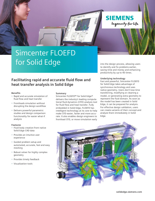
Summary Simcenter FLOEFD™ for Solid Edge® delivers the industry’s leading computa-tional fluid dynamics (CFD) analysis tool for fluid flow and heat transfer. Fully embedded in Solid Edge, FLOEFD has intelligent technology at its core to help make CFD easier, faster and more accu-rate. It also enables design engineers to frontload CFD, or move simulation early into the design process, allowing users to identify and fix problems earlier, saving time and money and enhancing productivity by up to 40 times. Underlying technology Fast and powerful, Simcenter FLOEFD for Solid Edge takes advantage of synchronous technology and uses native geometry. Users don’t lose time transferring, modifying or cleaning a model, or generating extra geometry to represent the fluid domain. As soon as the model has been created in Solid Edge, it can be prepared for analysis. For effective design validation, users can create variants of their concept and analyze them immediately in Solid Edge.Benefits • Rapid and accurate simulation of fluid flow and heat transfer• Frontloads simulation without disrupting the design workflow• Delivers powerful parametric studies and design comparison functionality for easier what-if analysisFeatures • Fluid body creation from native Solid Edge CAD data• Provides an intuitive user experience• Guided problem setup and automated, accurate, fast and easy meshing• Robust solver for highly complex geometry• Provides timely feedback• Visualization tools Simcenter FLOEFD for Solid EdgeFacilitating rapid and accurate fluid flow and heat transfer analysis in Solid Edge Simcenter FLOEFD for Solid EdgeUnique SmartCells™ technology allows use of a coarse mesh without sacrificing accuracy, and a robust mesher easily captures arbitrary and complex geome-try. As a result, the meshing process can be completely automated and requires less manual input.Simcenter FLOEFD for Solid Edge also delivers engineering outputs in a timely and intuitive manner, including reports in Microsoft Excel and Word.The expandable power of Simcenter FLOEFDSimcenter FLOEFD is extensible with the aid of optional modules for advanced analyses, including:• Advanced CFD module for special applications such as hypersonic flow for up to Mach 30, orbital radiation simulation such as for satellites, the NIST real gas database and gas combustion simulation• Heating, Ventilation and Air Conditioning (HVAC) module for designing occupied spaces, including buildings and vehicles. It includes special simulation capabilities, includ-ing comfort parameters and tracer studies, an additional radiation model and an extended database for build-ing materials• Electronics Cooling module for detailed simulation of electronics systems. It includes an extended data-base, packaging materials and physics such as joule heating• Light-Emitting Diode (LED) module for all lighting-specific simulations with the Monte Carlo radiation model, and a water film model for condensation and icing simulation of water films• Electronic Design Automation (EDA)Bridge for importing data from EDAsoftware, including Siemens DigitalIndustries, Cadence, Zuken andAltium, as well as import materialsand power maps of printed circuitboards (PCB) and definitions of ther-mal territories and network assem-blies (Delphi model)• Extended Design Exploration modulefor multi-parameter optimizationsleveraging the advanced HEEDSSherpa solver• Power Electrification module for moreaccurate thermal simulation of batter-ies with Equivalent Circuit Model(ECM) and Electrochemical-ThermalCoupled Model (ECT)• T3STER Automatic Calibration modulefor the design of calibrated thermalsemiconductor models fromSimcenter T3STER measurementssuch as integrated circuits (IC) andinsulated gate bipolar transistors(IGBT)• BCI-ROM + Package Creator module,which comprised of the BoundaryCondition Independent ReducedOrder Model (BCI-ROM) feature, forextracting dynamic compact thermalmodels from a 3D model; thermalnetlist extraction, for converting a 3Dmodel into an electrothermal modelfor Simulation Program withIntegrated Circuit Emphasis (SPICE);and package creator tool, for therapid creation of thermal models ofelectronic packages• Electronics Cooling Center module,offers the ultimate solution forelectronics cooling, includes theBCI-ROM + Package Creator, EDABridge, Electronics Cooling andT3STER Automatic Calibrationmodules and moreExtending value Solid Edge is a portfolio of affordable, easy to deploy, maintain and use soft-ware tools that advance all aspects of the product development process – mechanical and electrical design, simu-lation, manufacturing, technical docu-mentation, data management and cloud-based collaboration.Minimum system configuration • Windows 10 Enterprise or Professional (64-bit only) version 1809 or later• 16GB RAM• 65K colors• Screen Resolution: 1920x1080• 8.5GB of disk space required for installation © 2020 Siemens. A list of relevant Siemens trademarks can be found here . Excel and Word are trademarks or registered trademarks of Microsoft Corporation. Other trademarks belong to their respective owners.78033-C6 6/20 C Siemens Digital Industries Software /softwareAmericas +1 314 264 8499 Europe +44 (0) 1276 413200 Asia-Pacific +852 2230 3333。
点燃式发动机燃烧循环变动研究进展
第 54 卷第 12 期2023 年 12 月中南大学学报(自然科学版)Journal of Central South University (Science and Technology)V ol.54 No.12Dec. 2023点燃式发动机燃烧循环变动研究进展段雄波1,奉莉宁1,刘敬平2,孙志强1(1. 中南大学 能源科学与工程学院,湖南 长沙,410083;2. 湖南大学 机械与运载工程学院,湖南 长沙,410082)摘要:点燃式发动机燃烧循环变动对其动力性、经济性以及排放特性影响非常大,且影响燃烧循环变动的参数众多,且参数之间又相互影响、相互耦合,因此,阐述各类影响点燃式发动机燃烧循环变动参数间的内在联系与关联机制,探索影响燃烧循环变动相互耦合因素解耦分析方法具有重要的研究意义。
本文针对点燃式发动机燃烧循环变动特征参数及其表征方法、燃烧循环变动规律及其影响因素分析和燃烧循环变动数值模拟3个方面对点燃式发动机燃烧循环变动的研究方法及研究现状进行综述,指出:国内外学者对点燃式发动机燃烧循环变动产生的原因以及影响因素开展了深入研究;需发展新的考虑真实物理场的循环变动和循环爆震数值模拟方法以及对相互耦合参数解耦分析方法,阐明循环变动和循环爆震与燃料理化性质、控制和运行参数之间的内在关联机理,探索宽工况范围下循环变动和循环爆震参数调控方法及纠偏机制,以便为点燃式发动机高效清洁燃烧系统设计提供依据。
关键词:点燃式发动机;燃烧循环变动;特征参数;参数解耦中图分类号:TK40 文献标志码:A 开放科学(资源服务)标识码(OSID)文章编号:1672-7207(2023)12-4882-11Research progress in combustion cycle-to-cycle variations ofspark ignition enginesDUAN Xiongbo 1, FENG Lining 1,LIU Jingping 2, SUN Zhiqiang 1(1. School of Energy Science and Engineering, Central South University, Changsha 410083, China;2. College of Mechanical and Vehicle Engineering, Hunan University, Changsha 410082, China)Abstract: Combustion cycle-to-cycle variations in the spark ignition engine have great influences on its power, economy and emission characteristics. However, there are many parameters that affect the combustion cycle-to-cycle variations, and the parameters mutually affect and couple with each other. Therefore, it is an important and收稿日期: 2023 −02 −14; 修回日期: 2023 −04 −16基金项目(Foundation item):国家自然科学基金资助项目(52206140);湖南省科技创新计划项目(2021RC4006);中南大学创新驱动计划项目(2020CX008) (Project(52206140) supported by the National Natural Science Foundation of China; Project (2021RC4006) supported by the Science and Technology Innovation Plan of Hunan Province; Project(2020CX008) supported by the Innovation-Driven Plan of Central South University)通信作者:孙志强,博士,教授,从事清洁低碳能源技术研究;E-mail :*************.cnDOI: 10.11817/j.issn.1672-7207.2023.12.025引用格式: 段雄波, 奉莉宁, 刘敬平, 等. 点燃式发动机燃烧循环变动研究进展[J]. 中南大学学报(自然科学版), 2023, 54(12): 4882−4892.Citation: DUAN Xiongbo, FENG Lining, LIU Jingping, et al. Research progress in combustion cycle-to-cycle variations of spark ignition engines[J]. Journal of Central South University(Science and Technology), 2023, 54(12): 4882−4892.第 12 期段雄波,等:点燃式发动机燃烧循环变动研究进展significant research job to expound the internal relationships and correlation mechanism among various parameters affecting the combustion cycle-to-cycle variations of the spark ignition engine, and explore the decoupling analysis method of the coupling factors affecting the combustion cycle-to-cycle variations. In this paper, the research methods and current development of combustion cycle-to-cycle variations were reviewed from three aspects, i.e. characteristic parameters and characterization methods of combustion cycle-to-cycle variations, changing rules and influencing factors analysis of combustion cycle-to-cycle variations, and numerical simulation methods of combustion cycle-to-cycle variations. It is pointed out that, currently, scholars have already carried out in-depth research on the reasons and influencing effects of the combustion cycle-to-cycle variations in the SI engine. It is necessary to develop a new simulation method of the combustion cycle-to-cycle variations and cyclic knock and analysis of mutual coupling parameter decoupling method based on the real physical field, which are used to illustrate the intrinsic connections between the combustion cycle-to-cycle variations, cyclic knock, fuel physical and chemical properties, controlling and operation parameters, and explore the parameter control method and correction mechanism of the combustion cycle-to-cycle variations and cyclic knock under the wide range operating conditions, thereby proving a basis for the design of high efficiency and clean combustion spark ignition engine.Key words: spark ignition engine; combustion cycle-to-cycle variations; parameters decoupling; parameters decoupling为了促进汽车产业的发展,我国在《中国制造2025》中明确提出了将“节能与新能源汽车”作为重点发展领域,确定了“提升动力电池、驱动电机、高效内燃机等核心技术的工程化和产业化能力”的发展战略,为我国新能源汽车的发展和内燃机高效清洁燃烧技术发展指明了方向。
利用StarCCM+模拟K-epsilon湍流模型下的预混燃烧
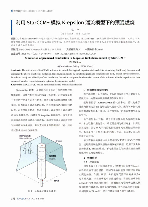
I利用StarCCM +模拟K-epsilon 湍流模型下的预混燃烧湛申(奇安信集团,北京100044)摘要:文章利用StarCCM +软件建立模拟纯体燃烧器的典型实验糢型,通过在K-epsi Ion 湍流模型中模拟预混燃烧,比较了不同 模型对模拟结果的影响。
为了验证糢拟的可靠性,文章将软件的仿真结果与其他研究团队真实测量的实验数据进行比对,进 而优化建立的仿真模型。
关键词:StarCCM +: K-epsilon 湍流模型;预混燃烧 文献标识码:A中图分类号:TP 31文章编号:20964137 (2021) 04-156-03DOI : 10.13535/j .cnki .10-1507/n .2021.04.64Simulation of premixed combustion in K-epsilon turbulence model by StarCCM +ZHAN Shen(Qi'anxin Group, Beijing 100044, China)Abstract : The article uses StarCCM + software to establish a typical experimental model for simulating bluff body burners , and compares the effects of different models on the simulation results by simulating premixed combustion in the K-epsilon turbulence model . In order to verify the reliability of the simulation , the article compares the simulation results of the software with the experimental data measured by other research teams to optimize the simulation model .Keywords : StarCCM +; K-epsilon turbulence model ; premixed combustioi钝体燃烧器实验模型本文将模拟分为2部分:进行冷却状态下的计算和引入 燃烧反应。
LMS复合材料的完整解决方案——介绍
LMS Solutions : A complete portfolio for composite material Introduction
Julien SIMON – Business Development Manager LMS Samtech Division
Automotive
Simulation challenges
Mechanical Industry
Simulate global behavior of composite structure that requires equivalent or superior performance to existing components with reduced mass and acceptable cost
Introduction
Composite materials :
engineered or naturally occurring materials made from two or more constituent materials First composite material Wood Cob, Bow Why ?
Intra-laminar & Inter-laminar
Ride & Handling Ride Comfort
• Highly Non-linear Subsystems
Coupling to Dedicated Simulation Applications for Composite Material/Laminate Properties
LMS复合材料的完整解决方案——介绍
dynamics modelling and analysis Correlation & Updating
High-fidelity Acoustic Simulation
Fastest
BEM/FEM, unique RayTracing Exterior and Interior
The AMESim model considering the ventilation circuit and the cabin with thermal exchanges Evaluate innovative ventilation strategies considering new composites materials for instance
Simulation of the complete system Description of physical phenomena based on
few “macroscopic” parameters
Multi-domain / Multi-level approach The simulation model is an assembly of
Composite Penetration in Various Market Segments
3 copyright LMS International - 2012
Relative Market Attractiveness by Region
4 copyright LMS International - 2012
Vibro-acoustics
Fatigue
Leveraging combined 3D CAE Strengths Advanced Simulation for Carbon-fibre structures in Automotive
Building and Environment

逄秀锋,等:我国建筑调适发展现状与前景指南与标准、建立激励机制以及政策法规、走向市场化产业化。
我国建筑调适的发展目前也遵循了这样一条发展路径,不同的是,我们的目标是用更短的时间完成西方国家四十多年走过的道路。
参考文献:[1]Mills E.Commissioning Capturing the Potential[J].ASHRAE Journal,2011,53(2):1-2.[2]逄秀锋,刘珊,曹勇.建筑设备与系统调适[M].北京:中国建筑工业出版社,2015:1-2.[3]Legris C,Choiniere D,Milesi Ferretti.Annex47Report1:Commissioning Overview[R].Paris:International Energy Agency,2010.[4]The U.S.Department of Energy.New DOE Research Strengthens Business Case for Building Commissioning[EB/OL].(2019-05-02)[2020-01-02].https://www.energy.gov/eere/buildings/articles/ new-doe-research-strengthens-business-case-building-commissioning.作者简介:逄秀锋(1976),男,辽宁人,毕业于美国内布拉斯加大学林肯分校,暖通空调专业,博士,研究员,研究方向:建筑调适技术、建筑系统能耗模拟、暖通空调系统故障诊断与优化控制、智慧建筑(xpang113@163.com)。
Energy and Buildingshttps://www.sciencedirect.com/journal/energy-and-buildings/vol/224/suppl/CVolume224,1October2020(1)A new analytical model for short-time analysis of energypiles and its application,by Jian Lan,Fei Lei,Pingfang Hu,Na Zhu,Article110221Abstract:An energy pile is a special form of vertical ground heatexchanger that couples the roles of structural support and heat trans-fer.Modeling the transient heat transfer process inside an energy pilehas importance;however,available analytical models either have in-sufficient calculation accuracy or are computationally demanding.Based on three existing models,this paper proposes a novel short-term hybrid composite-medium line-source(HCMLS)model,whichis not only efficient in computation but also more accurate than mosttraditional analytical models.The model is suitable for ground heatexchangers of various radii.Comparisons between the hybrid analyti-cal model and a numerical model are made for energy pile cases withdifferent parameters,including the thermal properties,borehole radii,relative positions of tubes,and number of tubes.In general,the hy-brid composite-medium line-source model gives credible predictionafter100min.The new model is further validated by the infinitecomposite-medium line-source(ICMLS)model,which is currentlythe most theoretically complete short-term model.Moreover,the newmodel is applied to thermal response tests(TRTs).The least dimen-sionless test duration for interpretations based on the modified hybridcomposite-medium line-source(C-HCMLS)solution is Fo>1.7.This study renders the application of in situ TRTs to energy pileswith large diameters feasible.Keywords:Ground heat exchanger;Energy pile;Short time re-sponse;Thermal response testing(2)Charging performance of latent thermal energy storage sys-tem with microencapsulated phase-change material for domestichot water,by Y.Fang,Z.G.Qu,J.F.Zhang,H.T.Xu,G.L.Qi,Arti-cle110237(3)Thermographic2D U-value map for quantifying thermalbridges in building fa ades,by Blanca Tejedor,Eva Barreira,Ricardo M.S.F.Almeida,Miquel Casals,Article110176(4)Urban morphology and building heating energy con-sumption:Evidence from Harbin,a severe cold region city,by Hong Leng,Xi Chen,Yanhong Ma,Nyuk Hien Wong,Tingzhen Ming,Article110143(5)UK Passivhaus and the energy performance gap,by Ra-chel Mitchell,Sukumar Natarajan,Article110240Building and Environmenthttps://www.sciencedirect.com/journal/building-and-environ-ment/vol/183/suppl/CVolume183,October2020(1)Residential buildings airtightness frameworks:A reviewon the main databases and setups in Europe and NorthAmerica,by Irene Poza-Casado,Vitor E.M.Cardoso,Ricar-do M.S.F.Almeida,et al,Article107221Abstract:The airtightness of buildings has gained relevance in thelast decade.The spread of the regulatory frameworks,the demand ofstricter requirements,schemes for testing and quality control,the cre-ation of airtightness databases and its analysis,is proof of this real-ity.The present review encompasses schemes developed in Europeand North America with regard to these aspects for national residen-tial sectors.A normative framework on requirements and recommen-dations at the national level is compiled.Whole building airtightnessdatabases are compared based on their structures and measurementdata acquisition protocols.Gathered complementary information notdirectly related to testing is analysed and airtightness influencing fac-tors importance and relationships are discussed.Weaknesses andstrengths in the different aspects of the existing database setups areidentified.Also,neglected or not entirely undertaken topics are pin-pointed together with the suggestion of possible opportunities forfuture works and changes.Amongst other relevant remarks and dis-cussions,it is concluded that the lack of uniformization in methodbetween countries,the need for a minimum data setup,the lack ofdata analysis on relating the energy impact with the advancement inrequirements of airtightness performance and the implemented setupsare some of the main issues to address in the near future.Keywords:Review paper;Airtightness;Regulation policy(2)A simulation framework for predicting occupant thermalsensation in perimeter zones of buildings considering directsolar radiation and ankle draft,by Shengbo Zhang,Jamie P.Fine,Marianne F.Touchie,William O’Brien,Article107096(3)Comparative review of occupant-related energy aspectsof the National Building Code of Canada,by Ahmed Abdeen,William O’Brien,Burak Gunay,Guy Newsham,HeatherKnudsen,Article107136Applied Energyhttps://www.sciencedirect.com/journal/applied-energy/vol/275/suppl/CVolume275,1October2020(1)Performance characteristics of variable conductance loopthermosyphon for energy-efficient building thermal control,byJingyu Cao,Xiaoqiang Hong,Zhanying Zheng,et al,Article115337Abstract:Variable conductance loop thermosyphon(VCLT)manip-ulates natural phase-change cycle to regulate the heat transfer.Its pri-mary advantages include high sustainability,simple design and lowcost.One of the potential applications of variable conductance loopthermosyphon is thermal control in buildings for achieving highenergy efficiency.In this study,a distributed steady-state model wasimplemented to determine the heat transfer control characteristics ofvariable conductance loop thermosyphon for the first time and evalu-ate its effectiveness on precise air-conditioning for buildings.The in-ternal flow resistance rises from0.002K/W to0.305K/W and theheat transfer rate decreases from468.5W to71.9W when the rela-tive opening degree of the regulating valve reduces from1.00to0.17under normal boundary conditions.The thermodynamic analysesshow that the regulating valve of the variable conductance loop ther-mosyphon can enable effective thermal control over a wide range ofheat transfer rate to accomplish indoor thermal comfort.The studyalso reveals that variable conductance loop thermosyphon can be ef-fectively adopted with various working fluids and over wide rangesof heat source and heat sink temperatures.Keywords:Air-conditioning;Energy-efficient building;Loop ther-mosyphon;Numerical study(2)Increasing the energy flexibility of existing district heatingnetworks through flow rate variations,by Jacopo Vivian,Dav-ide Quaggiotto,Angelo Zarrella,Article115411(3)A framework for uncertainty quantification in buildingheat demand simulations using reduced-order grey-box en-ergy models,by Mohammad Haris Shamsi,Usman Ali,EleniMangina,James O’Donnell,Article115141(2020-10-10《建筑节能》杂志社侯恩哲摘录)7。
physx cpu
physx cpuPhysX CPU: A Comprehensive OverviewIntroductionPhysX CPU is a physics engine technology developed by NVIDIA Corporation that allows for real-time physics calculations and simulations on a computer's central processing unit (CPU). This technology enables developers to create realistic and immersive virtual environments, enhance gaming experiences, and improve the accuracy of animations and visual effects. In this document, we will delve into the details of PhysX CPU, its features, advantages, and its impact in various industries.1. Background of PhysX CPU1.1 PhysX CPU DevelopmentPhysX CPU was initially developed by a company called AGEIA, which was later acquired by NVIDIA in 2008. This acquisition propelled the evolution of PhysX CPU technology and expanded its capabilities to leverage NVIDIA's extensive knowledge and expertise in graphics processing units (GPUs).1.2 Physics SimulationPhysX CPU primarily focuses on simulating physics in real-time, allowing for realistic interactions between objects in a virtual environment. It models physical phenomena such as gravity, collision detection, friction, and ragdoll dynamics, providing a more immersive and lifelike experience to users.2. Features and Capabilities of PhysX CPU2.1 Real-Time PhysicsPhysX CPU excels in performing complex physics calculations in real-time, delivering high fidelity simulations and accurate representations of real-world physics. This technology enables objects to interact with each other, respond to external forces, and move in a physically plausible manner.2.2 Robust Collision DetectionPhysX CPU incorporates advanced collision detection algorithms, ensuring objects interact and collide realistically. This capability is essential in applications such as video games, where accurate collision detection is crucial for gameplay mechanics, object interactions, and environmental dynamics.2.3 Dynamic Particle SystemsPhysX CPU supports dynamic particle systems, enabling the simulation of a large number of particles. These particles can exhibit complex behaviors, reacting to external forces, gravity, and collisions. This feature finds applications in fields such as fluid simulation, smoke simulation, or any scenario requiring the realistic representation of particle-based physical phenomena.2.4 Soft-Body SimulationPhysX CPU includes soft-body simulation capabilities, allowing for the accurate modeling of deformable objects. This feature is particularly useful in applications that require realistic simulations of cloth, flesh, paper, or any other object that can undergo deformation due to external forces.2.5 Vehicle Dynamics SimulationPhysX CPU provides a robust framework for simulating vehicle dynamics. It can accurately model the movement and behavior of vehicles, accounting for factors such as suspension, tire friction, weight distribution, and aerodynamics. This enables the creation of more immersive and realistic driving experiences.2.6 GPU AccelerationWhile PhysX CPU is primarily designed to leverage the computational power of the CPU, it also supports GPU acceleration. By offloading certain physics calculations to the GPU, developers can achieve significant performance gains and further enhance the realism and complexity of their applications.3. Applications of PhysX CPU3.1 Gaming IndustryThe gaming industry has been a primary beneficiary of PhysX CPU technology. Game developers utilize this physics engine to create lifelike environments, incorporate realistic object dynamics, and enable immersive gameplay interactions. PhysX CPU enhances the visual effects and responsiveness of games, contributing to a more enjoyable and engaging gaming experience.3.2 Virtual Reality (VR) and Augmented Reality (AR)PhysX CPU plays a crucial role in the development of VR and AR applications. By providing accurate physics simulations, it helps enhance the sense of presence and immersion in virtualenvironments. PhysX CPU enables realistic object interactions, which are vital for creating believable and interactive virtual worlds.3.3 Cinematic and Animation IndustriesPhysX CPU finds applications in the cinematic and animation industries, enabling accurate physics-based animations. It allows for the simulation of cloth, hair, and liquids, enabling realistic movement and behavior in animated characters and objects. PhysX CPU enhances the visual quality and realism of computer-generated imagery (CGI) in movies and animations.3.4 Architecture and EngineeringPhysX CPU can be utilized in the architecture and engineering fields to simulate physical structures, analyze how they respond to forces like wind and earthquakes, and perform stress and strain calculations. With PhysX CPU, engineers can create accurate virtual prototypes and iteratively refine designs, saving time and resources during the product development process.ConclusionPhysX CPU has revolutionized real-time physics simulations, offering developers the tools to create realistic and interactive virtual environments across various industries. With its advanced features, robust collision detection, and dynamic particle systems, PhysX CPU has had a significant impact on the gaming, VR/AR, cinematic, and engineering fields. As technology advances, PhysX CPU continues to evolve, offering even more capabilities and pushing the boundaries of what's possible in computer-generated simulations.。
全科规培考核-门诊SOAP病历模拟脚本英文版
全科规培考核-门诊SOAP病历模拟脚本英文版General Practice Training Assessment - Outpatient SOAP Medical Record Simulation ScriptWelcome to the Outpatient SOAP Medical Record Simulation Script for the General Practice Training Assessment. This script is designed to test your ability to accurately document patient encounters in a standardized format.Patient Encounter Scenario:You are seeing a 45-year-old female patient, Mrs. Smith, who presents with complaints of abdominal pain and bloating for the past week. She reports that the pain is dull and intermittent, worsens after meals, and is not associated with any specific trigger. She denies any nausea, vomiting, diarrhea, or changes in bowel habits. Mrs. Smith has a past medical history of irritable bowel syndrome and anxiety.SOAP Note Documentation:Subjective:- Chief Complaint: Abdominal pain and bloating- History of Present Illness: Onset, duration, characteristics, aggravating/alleviating factors- Past Medical History: Irritable bowel syndrome, anxiety- Review of Systems: Gastrointestinal, psychologicalObjective:- Vital Signs: Blood pressure, heart rate, respiratory rate, temperature- Physical Examination: Abdominal exam, bowel soundsAssessment:- Differential Diagnosis: Gastrointestinal conditions, anxiety-related symptoms- Working Diagnosis: Irritable bowel syndrome flare-up- Plan: Symptom management, follow-up in 2 weeksPlan:- Medications: Antispasmodic for abdominal pain- Lifestyle Modifications: Dietary changes, stress management techniques- Follow-Up: Return visit in 2 weeks for symptom reassessmentDocumentation Guidelines:- Use clear and concise language- Avoid medical jargon or abbreviations- Include relevant details for each section of the SOAP note- Document patient responses and provider observations accuratelyConclusion:This Outpatient SOAP Medical Record Simulation Script provides a structured framework for documenting patient encounters in a comprehensive and organized manner. Practice this script to improve your documentation skills and enhance your ability to communicate effectively with colleagues and patients.Good luck with your assessment!。
Autodesk Simulation Moldflow Communicator 2014 系统要
Autodesk® Simulation Moldflow®Communicator 2014 System Requirements01-28-2013Autodesk Simulation Moldflow Communicator© 2013 Autodesk, Inc. All rights reserved. Except as otherwise permitted by Autodesk, Inc., this publication, or parts thereof, may not be reproduced in any form, by any method, for any purpose.Certain materials included in this publication are reprinted with the permission of the copyright holder.TrademarksThe following are registered trademarks or trademarks of Autodesk, Inc., and/or its subsidiaries and/or affiliates in the USA and other countries: 123D, 3ds Max, Algor, Alias, Alias (swirl design/logo), AliasStudio, ATC, AUGI, AutoCAD, AutoCAD Learning Assistance, AutoCAD LT, AutoCAD Simulator, AutoCAD SQL Extension, AutoCAD SQL Interface, Autodesk, Autodesk Homestyler, Autodesk Intent, Autodesk Inventor, Autodesk MapGuide, Autodesk Streamline, AutoLISP, AutoSketch, AutoSnap, AutoTrack, Backburner, Backdraft, Beast, Beast (design/logo) Built with ObjectARX (design/logo), Burn, Buzzsaw, CAiCE, CFdesign, Civil 3D, Cleaner, Cleaner Central, ClearScale, Colour Warper, Combustion, Communication Specification, Constructware, Content Explorer, Creative Bridge, Dancing Baby (image), DesignCenter, Design Doctor, Designer's Toolkit, DesignKids, DesignProf, DesignServer, DesignStudio, Design Web Format, Discreet, DWF, DWG, DWG (design/logo), DWG Extreme, DWG TrueConvert, DWG TrueView, DWFX, DXF, Ecotect, Evolver, Exposure, Extending the Design Team, Face Robot, FBX, Fempro, Fire, Flame, Flare, Flint, FMDesktop, Freewheel, GDX Driver, Green Building Studio, Heads-up Design, Heidi, Homestyler, HumanIK, IDEA Server, i-drop, Illuminate Labs AB (design/logo), ImageModeler, iMOUT, Incinerator, Inferno, Instructables, Instructables (stylized robot design/logo),Inventor, Inventor LT, Kynapse, Kynogon, LandXplorer, LiquidLight, LiquidLight (design/logo), Lustre, MatchMover, Maya, Mechanical Desktop, Moldflow, Moldflow Plastics Advisers, Moldflow Plastics Insight, Moldflow Plastics Xpert, Moondust, MotionBuilder, Movimento, MPA, MPA (design/logo), MPI, MPI (design/logo), MPX, MPX (design/logo), Mudbox, Multi-Master Editing, Navisworks, ObjectARX, ObjectDBX, Opticore, Pipeplus, Pixlr, P ixlr-o-matic, P olarSnap, P ortfolioWall, P owered with Autodesk Technology, P roductstream, P roMaterials, RasterDWG, RealDWG, Real-time Roto, Recognize, Render Queue, Retimer, Reveal, Revit, RiverCAD, Robot, Scaleform, Scaleform GFx, Showcase, Show Me, ShowMotion, SketchBook, Smoke, Softimage, Softimage|XSI (design/logo), Sparks, SteeringWheels, Stitcher, Stone, StormNET, Tinkerbox, ToolClip, Topobase, Toxik, TrustedDWG, T-Splines, U-Vis, ViewCube, Visual, Visual LISP, Voice Reality, Volo, Vtour, WaterNetworks, Wire, Wiretap, WiretapCentral, XSI.All other brand names, product names or trademarks belong to their respective holders.ContentsChapter 1Supported Platforms . . . . . . . . . . . . . . . . . . . . . . . . 12 GB memory limit on 32-bit Windows systems . . . . . . . . . . . . . . 1System specifications for Windows platforms . . . . . . . . . . . . . . . 2 Chapter 2Graphics requirements . . . . . . . . . . . . . . . . . . . . . . . 3iiiiv1 Supported PlatformsSupported Windows platformsOperating SystemService PackWindows 8 (64-bit edition)Professional, Enterprise and UltimateBase version or later Windows 7 (64-bit edition)Professional, Enterprise and UltimateWindows 7 (32-bit edition)Base version or later Professional, Enterprise and UltimateSP 3 or laterWindows XP Professional (32-bit edition)Windows XP Professional (64-bit edition)SP 2 or later2 GB memory limit on 32-bit Windows systemsWindows 32-bit operating systems have a 2 GB memory limit per process;however there are some guidelines to help you avoid errors due to this memorylimit.A large number of open studies in a project may exceed the memory limit.■Close any open studies that are not being used at a given time.■Consider splitting one project with a large number of studies into two or more projects with a smaller number of studies in each.1Even a small number of large studies open in a project may exceed the memorylimit.■It is recommended to open only one study per project.Free resources (memory, swap space) on the machine.Add more resources (memory, swap space) to your machine.If you have tried the above options, but still exceed the 2GB memory limit,consider changing to a computer with a 64-bit Windows operating system. System specifications for Windows platforms Minimum and recommended hardware and software specifications for Windows platforms System componentRecommendedCPU speed2 GHz or higherMain memory (RAM)2 GB or higher for 32-bit machines, 4GB or higher for 64-bit machines Virtual memory/swap space2 GB or higherDisk space4 GB or higher for free disk space (atleast 2GB free disk space for installa-tion)Web browserInternet Explorer 7 or laterAdobe Flash Player 9.0 or laterVideo viewerThird-party softwareThe help system requires Microsoft Internet Explorer 7.0 or later.■Flash Player 9.0 or later is required for 32-bit browsers.■If you are using a 64-bit browser, you may have to Download active-x for 64-bit Windows - for Internet Explorer only.2 | Chapter 1 Supported Platforms2 Graphics requirementsThe graphic requirements listed here reflect the minimum required to obtain acceptable simulations.■512 MB DRAM or higher, OpenGL-capable graphics card. Ensure you have installed the latest driver for your card. Please refer to the card manufacturer's website for drivers and instructions.■24-bit color setting at 1280 × 1024 or higher screen resolution.NOTE Autodesk does not guarantee the use of any particular graphics card.Autodesk will make every effort to work with card manufacturers to resolve any problems that may arise in the use of our software with a particular card. However, we cannot guarantee that all graphics-related issues can be fixed, as they may lie within the card manufacturer's drivers rather than Autodesk software.RecommendedThe software makes extensive use of OpenGL and texture mapping, therefore any device offering OpenGL acceleration and texture memory will give improved performance.34。
Smoldering Combustion
Adapted from Baker, R R, PECS, 7, (1981), 135-153
Numerical Implementation in COMSOL
2-D axisymmetric domain employed Physics interfaces used: •) • Free and Porous Media Flow: Regions 1,2,3,4 (Source term in Region 2 accounts for solid-to-gas reaction) • Transport of Concentrated Species: Regions 1,2,3,4 (Source terms in Region 2 account for reactions) • Heat Transfer in Fluids: Regions 1,2,3,4 (Source terms account for interphase heat transfer in Regions 2,3,4)
[m] [m]
Riley D, et al., PhysicoChemical Hydrodynamics, 7, (1986), 255-279 Muramatsu M et al., Beitr. Tabakforsch, 11, (1981), 79-86 Saidi et al., App. Math. Mod., 31 (2007) 1970-1996
Condensation and Filtration
Oxidation
Pyrolysis
• Local thermal equilibrium between gas and solid does not always hold
- 1、下载文档前请自行甄别文档内容的完整性,平台不提供额外的编辑、内容补充、找答案等附加服务。
- 2、"仅部分预览"的文档,不可在线预览部分如存在完整性等问题,可反馈申请退款(可完整预览的文档不适用该条件!)。
- 3、如文档侵犯您的权益,请联系客服反馈,我们会尽快为您处理(人工客服工作时间:9:00-18:30)。
Eurographics/ACM SIGGRAPH Symposium on Computer Animation(2004)Posters and Demos R.Boulic,D.K.Pai(Editors)A Simulation Framework for Combustion,Burning,andDecomposition of Solid ObjectsZ.Melek†and J.Keyser‡Department of Computer Science,Texas A&M University,USAAbstractWe present a simulation framework to integrate several aspects of the combustion and burning process in a unifiedand modular manner.Categories and Subject Descriptors(according to ACM CCS):I.3.5[Computer Graphics]:Physically Based Model-ing;1.IntroductionRecent models within the computer graphics community [MBR∗02,NFJ02,FOA03]have begun to simulatefire based onfluid simulations.While their models implement somefire related phenomena,there have not been any of-fering a framework that addresses all the majorfire-related phenomena.In this work,we present a framework combin-ing different modules to simulate many aspects of the burn-ing process in a unified simulation.It consists of two main modules,which are afire/flame simulation and a solid ob-ject simulation.Each of these is composed of several sub-modules dealing with different phenomena.The two simula-tions are coupled together by pyrolysis.2.Fire SimulationThefire module is responsible for air motion,gas distribu-tion,and heat generation.It models the combustion process, which generates heat and drives the air motion.•It should track distribution of different gases.•Motion of the hot air needs to be modeled,including tracking which parts of the simulation domain are covered by objects.†This work was supported by NSF grant CCR-0220047.‡/keyser/graphics/•The combustion process,which consumes fuel gas and generates smoke and heat,should be modeled.•Heat transfer should be modeled explicitly.In our simpleflame model[MK03],we transport the fuel and exhaust gases with the motion of the air,creating a dy-namic3-gas system.We assume there is only one moving gas,which is inviscid,incompressible,and constant density. Thefluid motion[FSJ01]is applied to advect three quanti-ties:fuel gas,exhaust gas,and heat.We simulate the com-bustion process by combining fuel and oxidizer in a cell, creating additional exhaust gas and heat in the cell.Solid objects in pyrolysis provide fuel gas to the module,simi-lar to any generic fuel source.Heat transfer is modeled in three stages:heat transfer in the air,heat transfer between the air and the solid,and heat conduction within solids.This three-stage heat transfer model enables us to treat solids with varying thermal properties.Heat convection in air is handled using semi-Lagrangian advection,which simulates moving air currents carrying heat.Radiative heat transfer is approx-imated as a diffusion process using implicit integration. 3.Solid ObjectsThe solid objects module consists of heat transfer,object de-composition,and a rigid body solver.•Information must be provided about which parts of the scene are occupied by the objects.•Heat triggers pyrolysis,which generates fuel gas.•During pyrolysis,solid objects deform under decomposi-tion.•Objects should undergo rigid body motion.c The Eurographics Association2004.Z.Melek&J.Keyser/A Simulation Framework for Combustion,Burning,and Decomposition of SolidObjectsFigure1:Different oriented burning matchesOur model for decomposition is thefirst model in CG lit-erature for defining decomposing objects under combustion.Two complementary representations are used.First repre-sentation,solid fuel amount,represents how much solid fuelwe still have available at the cell.A second representation,the distancefield,represents the decomposed solid includingboth the solid fuel left and the residue(ashes)in that cell.Al-though the two representations are equivalent at the start ofthe simulation,we intentionally allow them to diverge dur-ing the simulation.The decomposition of the burning solidis modeled as a moving boundary in the distancefield,andis defined in the direction of the fuel consumption gradientwith rate of solid fuel consumption.We apply level set meth-ods[OF02]on the distancefield representation.As objectsdecompose,thin or disconnected pieces can be created.Weuse a set of particles placed at the vertices of the visualiza-tion polygons,and interpolation on the distancefield grid ofthe other objects directly gives us the distance to the bound-ary,letting us know whether the objects have collided.4.Module Interface andExecutionFigure2:Integration between simulation modulesThe two simulations described above are joined throughthe pyrolysis step.A pyrolysis time step begins transfer-ringfilled/unfilled information from the solids into theflamemodule.The air-solid boundary is traced and the heat differ-entials are used to exchange heat.The next step is transfer-ring forces in thefluid motionfield.Solid objects are sim-ulated within their own space.The pyrolysis cells convertsolid fuel into fuel gas as a function of heat,and it is passedto theflame simulator.The fuel conversion differential drivesthe object decomposition process.Decomposing objects arechecked to see if they have separated into two or more parts,and rigid body motion is determined.5.ConclusionWe have presented a method that for thefirst time inte-grates afluid-basedflame simulator,combustion model,heattransfer model,solid pyrolysis model,solid decompositionmodel,and rigid body simulator into a common framework.It isflexible,allowing for easy replacement of simulators inany one part of the model,fairly independently of the otherportions of the model.References[FOA03]F ELDMAN B. E.,O’B RIEN J. F.,A RIKANO.:Animating suspended particle explosions.In Proc.of ACM SIGGRAPH’03(aug2003),pp.708–715.1[FSJ01]F EDKIW R.,S TAM J.,J ENSEN H.W.:Visualsimulation of smoke.Proc.of ACM SIGGRAPH’01(2001),15–22.1[MBR∗02]M C G RATTAN K. B.,B AUM H.R.,R EHMR.G.,H AMINS A.,F ORNEY G.P.,F LOYDJ.E.,H OSTIKKA S.,P RASAD K.:Fire dynam-ics simulator technical reference guide.Tech.Rep.NISTIR6783(2002).1[MK03]M ELEK Z.,K EYSER J.:Interactive simulationof burning objects.Proc.of Pacific Graphics’03(2003),462–466.1[NFJ02]N GUYEN D.,F EDKIW R.,J ENSEN H.W.:Physically based modeling and animation offire.Proc.of ACM SIGGRAPH’02(2002),721–728.1[OF02]O SHER S.,F EDKIW R.:Level Set Methodsand Dynamic Implicit Surfaces.Springer Ver-lag,2002.2c The Eurographics Association2004.。