VMware网络虚拟化产品NSX安装配置指南
实验二 虚拟机VMware的安装与配置
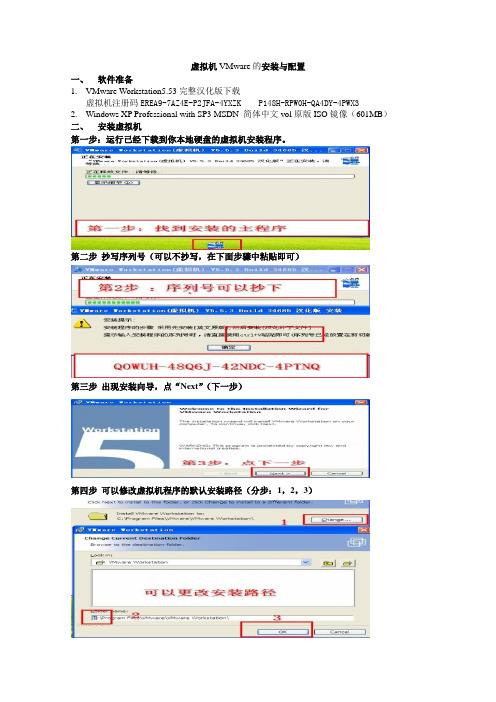
虚拟机VMware的安装与配置一、软件准备1.VMware Workstation5.53完整汉化版下载虚拟机注册码EREA9-7AZ4E-P2JFA-4YXZK P148H-RPW0H-QA4DY-4PWX32.Windows XP Professional with SP3 MSDN 简体中文vol原版ISO镜像(601MB)二、安装虚拟机第一步:运行已经下载到你本地硬盘的虚拟机安装程序。
第二步抄写序列号(可以不抄写,在下面步骤中粘贴即可)第三步出现安装向导,点“Next”(下一步)第四步可以修改虚拟机程序的默认安装路径(分步:1,2,3)第五步更改安装路径后,点“Next”(下一步)第六步选择安装选项后,点“Next”(下一步)(依据个人习惯选择)第七步开始安装,点“Install”(安装)第八步填写注册信息第九步安装完成,点“Finish”(完成)第十步完成汉化,点“确定”三、启动虚拟机第一步双击桌面上的虚拟机图标(分步:1,2,3)第二步新建虚拟机(分步:1,2)第三步选择虚拟机配置(仔细阅读两个选项文字说明后,如果还看不懂,那就选“典型”吧)第四步选择打算在虚拟机里安装的操作系统(分步:1,2,3)第五步设置虚拟机名称和位置提示:虚拟机名称:给你自己建立的虚拟机起一个名字(任意命名,但最好起有意义的名字)位置:决定你建立的虚拟机占用的硬盘位置(就是指定一个文件夹)第六步配置虚拟机网络提示:此步骤用来配置虚拟机访问网络,按你的实际情况选择第七步为虚拟机指派磁盘空间提示:即为第五步中指定文件夹下占用的磁盘空间第八步配置虚拟机的光盘驱动器(分步:1,2,3,4)提示:如果在虚拟机中用映像文件(ISO文件)安装系统,选择“使用ISO镜像”;如果用光盘安装系统,选择“使用物理驱动器”第九步虚拟机配置完毕,启动虚拟机。
VMWare NSX网络与安全解决方案

收益
跨数据中心扩展多租户 在3层基础架构上实现2层网络 基于VXLAN, STT, GRE等实现Overlay 可跨越多个物理主机和网络交换机的逻辑交换 服务
逻辑交换 –将网络的扩展性提高1000倍
14
VMware NSX
逻辑交换服务
15
VMware NSX三层路由: 分布式、功能全面
NSX管理器
逻辑网络
13
VMware NSX逻辑交换机
Logical Switch 1
Logical Switch 2
Logical Switch 3
挑战
• • • • 应用/租户之间的分段 虚拟机的移动性需要大二层网络 大的二层物理网络扩展导致生成树问题 硬件内存 (MAC, FIB)表限制 • • • •
Tenant A Tenant B
L2 L2 L2 L2 L2 L2 L2 L2
CMP
Tenant C
控制器集群
VM to VM Routed Traffic Flow
挑战
• 物理基础架构的扩展性存在挑战—— 路由扩展性 • 虚拟机的移动性存在挑战 • 多租户路由的复杂度 • 流量的发夹问题
收益
• • • • • 在虚拟化层实现分布式路由 动态的,基于API的配置 完整功能——OSPF, BGP, IS-IS 基于租户的逻辑路由器 可与物理交换机协同
收益
• • • • • 分布在虚拟化层 动态,基于API的配置 使用VM名字和基于标识的规则 线速,每主机15+ Gbps 对封装的流量完全可见
性能与扩展性 ——1,000+主机 30Tbps防火墙
18
虚拟网络:一个通过软件定义的完整网络
VMware_网络虚拟化平台NSX及其实现

好处
• • • • • 在Hypervisor层实现分布式路由 动态的, 基于API的配置 动态路由– OSPF, BGP, IS-IS Logical Router 支持多租户 支持与物理路由器之间跑动态路由
分布式路由– 灵活实现多租户网络
15
分布式逻辑路由网络
Overview
VM
VM
• 虚拟网络之间实现三层路由互联
Physical or Virtual
逻辑交换网络 分布式交换
优化东西向流量
逻辑路由器
集成于kernal 25,000 CPS 2.5 million Sessions
FW, LB, VPN
分布式防火墙 分布式路由 虚拟网络
Edge Services
VMware NSX Software
软件 硬件
Hypervisor
运维模式
独立于硬件
Create, Delete, Grow, Shrink
应用透明 可编程监控 可扩展
向操作虚机一样管理网络…
6
介绍VMware NSX
L2 Switch
L3 Router
Firewall
Load Balancer
借助NSX实现网络虚拟化
像管理虚机一样管 理网络
软件 硬件
7
网络虚拟化 需求
任意网络硬件
自动化及运营管理
• • • •
本节偏重逻辑交换及路由功能 合作厂商可 扩展性 简单介绍4-7层服 务
•
NetX(VMware Network Extensibility Program )高级集成
32
NSX vSphere优化版组件
使用
CMP
VMware NSX网络虚拟化 - 设计指南-VMware NSX for vSphere (NSX-V) 网络虚拟化

VMware®NSX for vSphere (NSX-V) 网络虚拟化设计指南目标受众 (4)概述 (4)网络虚拟化简介 (5)NSX-v 网络虚拟化解决方案概述 (5)控制平面 (5)数据平面 (5)管理平面和使用平台 (6)NSX 功能性服务 (6)NSX-v 功能组件 (7)NSX Manager (7)Controller 集群 (8)VXLAN 入门 (10)ESXi Hypervisor 与 VDS (11)用户空间和内核空间 (12)NSX Edge 服务网关 (12)传输域 (14)NSX 分布式防火墙 (DFW) (15)NSX-v 功能性服务 (21)多层应用部署示例 (21)逻辑交换 (22)多目标流量的复制模式 (23)多播模式 (23)单播模式 (25)混合模式 (26)填充 Controller 表 (27)单播流量(虚拟到虚拟通信) (28)单播流量(虚拟到物理通信) (29)逻辑路由 (32)逻辑路由组件 (33)逻辑路由部署选项 (37)物理路由器作为下一个跃点 (38)Edge 服务网关作为下一个跃点 (38)逻辑防火墙 (40)网络隔离 (41)网络分段 (41)充分利用抽象化 (42)高级安全服务注入、串联和引导 (43)跨物理和虚拟基础架构的一致的可见性和安全模式 (44)通过 NSX DFW 实现的微分段用户场景和实施 (45)逻辑负载均衡 (49)虚拟专用网络 (VPN) 服务 (52)L2 VPN (53)L3 VPN (54)NSX-v 设计注意事项 (55)物理网络要求 (56)简易性 (57)分支交换机 (57)主干交换机 (58)可扩展性 (58)高带宽 (58)容错 (59)差异化服务–服务质量 (60)NSX-v 部署注意事项 (61)NSX-v 域中的 ESXi 集群设计 (62)计算、边缘和管理集群 (62)NSX-v 域中的 VDS 上行链路连接 (64)NSX-v 域中的 VDS 设计 (68)ESXi 主机流量类型 (68)VXLAN 流量 (69)管理流量 (69)vSphere vMotion 流量 (69)存储流量 (70)适用于 VMkernel 接口 IP 寻址的主机配置文件 (70)边缘机架设计 (71)NSX Edge 部署注意事项 (72)NSX 第 2 层桥接部署注意事项 (80)总结 (82)目标受众本文档面向有兴趣在 vSphere 环境中部署 VMware® NSX 网络虚拟化解决方案的虚拟化和网络架构师。
VMware NSX网络虚拟化概览

VMware NSX网络虚拟化概览目录序言 (2)1. VMware NSX网络虚拟化解决方案简介 (2)1.1 VMware服务器虚拟化的前世今生 (2)1.2 服务器虚拟化的优势移植到了网络虚拟化 (8)1.3 NSX解决方案概览 (10)1.4 NSX网络虚拟化应用场景 (14)2.当前主流的Overlay隧道技术 (16)2.1 VXLAN技术 (16)2.2 NVGRE技术 (18)2.3 STT技术 (18)2.4 三种Overlay技术的对比和应用场景 (19)2.5 下一代Overlay技术——Geneve (20)3.各厂商的网络虚拟化解决方案 (22)3.1 Cisco ACI解决方案 (22)3.2 在MicrosoftHyper-V中实现网络虚拟化 (24)3.3 JuniperContrail解决方案 (25)3.4 各厂商网络虚拟化解决方案的比较 (26)4.与VMwareNSX相关的认证 (28)4.1 VMware认证体系简介 (28)4.2 与NSX相关的VMware认证与考试 (30)总结 (31)序言网络虚拟化技术诞生后,有不少厂商都推出了所谓的网络虚拟化解决方案。
这些厂商实现“网络虚拟化”的方式各异,有些是自己研发的项目,有些是通过收购,有些是利用开源项目进行再开发。
而VMware NSX网络虚拟化平台的基本架构到底是怎样的,它与别的厂家有哪些不同?这些问题会在本章进行探讨。
1. VMware NSX网络虚拟化解决方案简介尽管VMware NSX网络虚拟化平台是通过收购Nicira而获得的,但是在收购一年多时间之后,NSX才正式发布。
在这一年多时间里,VMware的研发人员与前Nicira的极客们一起通力合作,将VMware服务器虚拟化平台与Nicira网络虚拟化平台进行了融合,我们现在会发现NSX架构和技术细节(尤其是用于vSphere平台的NSX-V),其实与早期的Nicira NVP平台还是有很大区别,它增加了很多VMware的基因在里面。
VMware虚拟化配置手册
VMware虚拟化配置手册1.服务器安装硬件要求确保主机符合 ESXi 6.0 支持的最低硬件配置。
必须具有以下硬件和系统资源,才能安装和使用 ESXi 6.0:ESXi 6.0 将仅在安装有 64 位 x86 CPU 的服务器上安装和运行。
ESXi 6.0 要求主机至少具有两个内核。
ESXi 6.0 仅支持 LAHF 和 SAHF CPU 指令。
已知的 64 位处理器:所有 AMD Opteron 处理器所有 Intel Xeon 3000/3200、3100/3300、5100/5300、5200/5400、5500/5600、7100/7300、7200/7400和 7500 处理器至少 2 GB 的内存。
一个或多个千兆或 10GB 以太网控制器。
一个或多个以下控制器的任意组合:基本 SCSI 控制器。
Adaptec Ultra-160 或 Ultra-320、LSI Logic Fusion-MPT 或者大部分 NCR/SymbiosSCSI。
RAID 控制器。
Dell PERC(Adaptec RAID 或 LSI MegaRAID)、HP Smart Array RAID 或IBM(Adaptec) ServeRAID 控制器。
SCSI 磁盘或包含未分区空间用于虚拟机的本地(非网络)RAID LUN。
ESXi 为多个 64 位客户机操作系统提供支持。
使用 64 位客户机操作系统运行虚拟机的主机有下列硬件要求:对于基于 AMD Opteron 的系统,处理器必须为 Opteron Rev E 或更高版本。
对于基于 Intel Xeon 的系统,处理器必须包括对 Intel 的 Virtualization Technology (VT) 的支持。
许多CPU 支持 VT 的服务器可能默认禁用 VT,因此必须手动启用 VT。
如果CPU 支持 VT 但在 BIOS 中看不到此选项,请联系供应商以获得可启用 VT 支持的 BIOS 版本。
VMware虚拟化配置手册(完整版)
VMware虚拟化培训手册一、VMware虚拟化架构概述1.1VMware虚拟化架构图如上图所示,虚拟化由物理主机(即ESXI主机)、虚拟化管理程序(vCenter Server)、虚拟机(操作系统)、存储等基本组成。
1.2登陆ESXI模式概述VMware虚拟化需要以下安装程序:vSphere Client、ESXI、vCenter Server,三者之间的关系如下图示:登陆模式区别:(1)vSphere Client- ESXI主机,如下图示(2)vSphere Client- vCenter Server-ESXI主机,如下图示区别:通过vCenter Server登陆可以管理其他物理主机以及对虚机的管理操作(克隆,迁移,模板等)。
1.3数据存储概述如上图所示,VMware中的存储主要有本地磁盘(ESXI主机的磁盘)、磁盘阵列;在虚拟化中存储技术主要有直接连接、光纤通道、FCoE、Iscsi、NAS。
1.4 VMware虚拟网络如上图所示,虚拟网络由外部环境(物理交换机)、物理主机(ESXI主机)组成;虚机可以通过虚拟交换机连接到不同的Vlan,实现虚机的高可用性。
二、VMware虚拟化部署1、部署硬件准备1.1硬件架构图注:此图为每台服务器与磁盘阵列的连接图;每台服务器需要四块HBA,每两块连接一台磁盘阵列(HBA卡冗余);虚拟化高可用的应用中需要共享存储2-5个,每增加一台磁盘阵列,服务器需增加两块HBA卡。
1.2服务器硬件要求CPU支持虚拟化、主板支持至少4块HBA卡、内存不低于64G。
1.3共享存储(1)创建虚拟磁盘登陆磁盘阵列管理端软件,P6550菜单下共包含五个子项:Virtual Disks、Hosts、Disk Groups、Data Replication、Hardware。
单击“Virtual Disks”,进入虚拟磁盘页面,如下图所示:在右侧页面中,单击“Create Vdisks”按钮,出现下图所示:在Name对话框内输入要创建的虚拟磁盘的名称,在Size对话框内输入要划分磁盘的空间大小,在Redundancy右侧选择冗余级别为“Vraid6”,单击“Create Vdisks”,系统操作完成后出现下图所示:单击“OK”按钮,完成虚拟磁盘创建(如需继续创建新的虚拟磁盘,单击“Create more Vdisks”按钮)。
NSX网络虚拟化平台安装手册
10为NSX准备主机群集51
11向准备好的群集添加主机55
12从准备NSX部署的群集中移除主机57
13配置VXLAN传输参数59
14分配分段ID池和多播地址范围63
15添加传输区域67
16添加逻辑交换机71
17添加分布式逻辑路由器79
18添加Edge服务网关91
19在逻辑(分布式)路由器上配置OSPF101
通过网络虚拟化,与网络虚拟机管理程序等效的功能可在软件中重现第2层到第7层的一整套网络服务(例如,交换、路由、访问控制、防火墙、QoS和负载平衡)。因此,可通过编程方式任意组合这些服务,只需短短数秒,即可生成独一无二的独立虚拟网络。
通过网络虚拟化,带来了类似于服务器虚拟化的优势。例如,就像虚拟机独立于基础x86平台并允许IT将物理主机视为计算容量池一样,虚拟网络也独立于基础IP网络硬件并允许IT将物理网络视为可以按需使用和调整用途的传输容量池。与传统架构不同的是,无需重新配置基础物理硬件或拓扑,即可通过编程方式置备、更改、存储、删除和还原虚拟网络。与企业从熟悉的服务器和存储虚拟化解决方案获得的功能和优势相匹配,这一革命性的联网方式可发挥软件定义的数据中心的全部潜能。
管理层面
NSX管理层面由NSXManager构建,是NSX的集中式网络管理组件。该层面提供单个配置点和RESTAPI入口点。
NSX Manager可作为虚拟设备安装在vCenter Server环境中的任意ESX™主机上。NSX Manager和vCenter是一对一的关系。NSX Manager的每个实例对应于一个vCenter Server。在跨vCenter NSX环境中,情况也是这样。
消费平台
NSX的消费使用可通过vSphereWebClient中的NSXManager用户界面查看。通常,最终用户将网络虚拟化与其云管理平台相融合,以部署应用。NSX通过RESTAPI提供丰富的集成功能,几乎可集成到任何CMP中。还可通过VMwarevCloudAutomationCenter、vCloudDirector和带有适用于NSX的Neutron插件的
VMware服务器虚拟化环境搭建手册完整版
VMware服务器虚拟化环境搭建手册一、安装前的打算 (2)1.1打算vSphere (2)1.2打算DNS (2)二、安装ESXi server (2)三、安装Vcenter server (6)3.1软硬件需求: (6)3.2安装前数据库打算: (7)3.3vCenter Server 4.0安装: (11)四、通过模板部署虚拟机 (17)4.1制作虚拟机模板 (17)4.2通过模板部署虚拟机: (18)4.3 SID问题 (23)五、vSwitch网络配置 (33)六、FC SAN Storage配置 (34)七、配置VMotion (39)八、vSphere HA配置 (40)8.1配置前打算 (40)8.2 vSphter Cluster配置步骤 (43)VMware vSphere 4 是VMware虚拟架构套件的基础组成部分,是动态、自我优化的IT 基础结构的基础。
VMware vSphere 4是一个强健、经过生产验证的虚拟层,它干脆安装在物理服务器的裸机上,将物理服务器上的处理器、内存、存储器和网络资源抽象到多个虚拟机中。
依据统计,对于传统的服务器应用方式,通常服务器的平均利用率在5-15%之间,而采纳虚拟架构整合后,服务器的平均利用率可达到60%-80%。
我们完全可以通过在2台高配置的2路6-8核服务器上创建10-16个虚拟服务器的方式,来完成传统方式须要10-16台的低配置服务器才能完成的工作,用户在降低成本的同时,还大大削减了环境的困难性,降低了对机房环境的需求,同时具有更敏捷稳定的管理特性。
此次测试服务器虚拟化架构如下:一、安装前的打算1.1打算vSphere打算vSphere并安装vCenter Server。
vSphere 4.1中的vCenter Server须要Windows 2023/2023 64bit的支持,建议运用2vCPUs、3G内存。
ESXi1140.1140.101ESXi1150.1150.101vCenter 0.1110.1011.2打算DNS可以通过DNS 正确解析域名两台ESX主机的域名(1)通过建立DNS 服务器,在DNS服务器里分别为两台ESX 服务器建立地址解析。
NSX网络虚拟化整体解决方案

自助化应用组装
应用蓝图
应用服务
应用发布标准化
自助服务 门户
基础架构服务
服务目录
无需管理员参与
软件定义数据中心
管理
监控
自动化
软件定义网络 虚拟化主机与存储
基础架构云
应用服务云
数据中心网络现状及面临的挑战
12
数据中心网络的现状
POD C:应用C
X86 服务器
接入层
L2
汇聚层
安全边界
L3
安全边界 汇聚层 L3 L2 接入层
▪ 每个组件都在特定的层进行操作。
使用模式 管理层 控制层
数据层
NSX 概述:数据层组件
▪ 数据层负责处理端点间的数据流。
使用模式
管理层
控制层
数据层
NSX Virtual Switch
分布式 交换机
ESXi
VXLAN
分布式 逻辑路由器
防火墙
虚拟化管理程序内核模块
• VMware NSX Virtual Switch™ NSX Edge • 分布式网络边缘 服务网关 • 线速性能
通用网络硬件
虚拟网络
网络虚拟化带来的价值
打破壁垒:使网络及其相关服务部署不再受 制于底层物理网络硬件和物理位置的限制
✓ 实现按需/自动化部署虚拟网络 ✓ 按需动态部署虚拟网络,不受物理位置限制 ✓ 面向对象的QoS以及安全策略配置 ✓ 集中控制,系统性的可视, 监控与管理 ✓ 逻辑区域完全隔离 (L2 & L3) ✓ 95+% 减少物理网络资源消耗(IP,VLAN,MAC地址等) ✓ 智能边界,分布式转发
• 虚拟化之后
– 数千台虚拟机 – 服务器和物理交换机的连接变为VLAN Trunking – 不同的团队管理不同的网络组件 – Features仍然依赖于硬件功能 – 绝对数量的服务器,加剧了复杂的网络服务(如防火墙等)的
vmware虚拟机使用手册
VMware虚拟机使用手册如下:
一、安装VMware虚拟机软件
1. 下载并安装VMware软件。
2. 打开虚拟机软件,根据向导进行安装。
3. 等待安装完成,输入许可证密钥。
二、新建虚拟机
1. 点击“新建虚拟机”按钮。
2. 选择“典型安装”选项。
3. 选择稍后安装操作系统。
4. 选择要安装的系统类型。
5. 选择虚拟机文件的位置。
6. 调整需要分配硬盘的大小。
7. 配置完成,稍后调整硬件。
8. 编辑虚拟机硬件。
9. 内存建议大于2G,处理器内核大于2个,网络选择NAT。
10. 点击光驱,配置光驱文件,设备状态要勾选启动时连接。
11. 开启虚拟机,出现此界面要点进虚拟机中。
12. 等待进入系统后,打开我的电脑,点击光驱,安装VMware Tools。
三、优化虚拟机设置
1. 打开虚拟机设置,调整CPU信息、内存、网络等参数。
2. 移除不需要的组件,如软盘等。
3. 优化虚拟机设置,提高运行效率。
以上是VMware虚拟机使用手册的主要内容,供您参考。
在使用过程中,请注意备份重要数据,并按照相关说明进行操作,以确保虚拟机的稳定性和安全性。
部署NSX网络和安全
部署NSX网络和安全1.网络规划:首先需要对网络进行规划,确定需要部署NSX的区域和规模。
在规划过程中需要考虑网络的拓扑结构、IP地址分配方案、路由策略等。
此外,还需要评估当前的网络设备和组件是否支持NSX的部署。
2.部署NSX Manager:NSX Manager是NSX的核心组件,负责管理和配置NSX网络和安全功能。
在部署NSX Manager之前,需要确保已满足其硬件和软件要求。
部署NSX Manager可以通过虚拟机在vSphere环境中进行,也可以使用物理硬件进行部署。
3.部署NSX Controller:NSX Controller是NSX的另一个核心组件,负责提供控制平面功能。
在部署NSX Controller之前,需要确定所需的控制器数量,通常建议至少部署三个控制器以提供冗余和高可用性。
部署NSX Controller可以通过虚拟机进行,也可以使用物理硬件进行部署。
4.部署NSX Edge:NSX Edge是NSX的边缘路由器,提供网络边缘的路由和安全功能。
在部署NSX Edge之前,需要规划和设计边缘路由器的功能和配置,包括外部网络连接、NAT配置、VPN配置等。
部署NSX Edge可以通过虚拟机进行,也可以使用物理硬件进行部署。
5.创建逻辑交换机和端口组:逻辑交换机是NSX中的虚拟交换机,用于连接虚拟机和其他网络设备。
在部署NSX之前,需要创建逻辑交换机,并将物理网络中的端口组与逻辑交换机关联起来,以实现虚拟机和物理网络之间的通信。
6.配置网络和安全策略:一旦部署了NSX网络和安全组件,就可以开始配置网络和安全策略。
这包括配置防火墙规则、负载均衡、虚拟私有网络、IP地址分配和路由等。
配置过程还可以使用NSX提供的网络和安全服务,如分布式防火墙、虚拟隧道等。
7.测试和验证:在部署NSX网络和安全之后,需要进行测试和验证,确保网络和安全功能正常运行。
测试可以包括网络连通性测试、防火墙策略测试、负载均衡测试等。
NSX-T 安装配置手册

对于这篇博文,我们将使用第一种方法,即“通过 NSX Manager UI 自动化”
通过 NSX Manager UI“自动安装 NSX-T 控制器”的先决条件如下:
1. 部署了 NSX-T Manager 2. 部署了 vCenter Server 和 vSphere ESXi 主机。 3. vSphere ESXi 主机已注册到 vCenter Server。 4. vCenter Server 作为“计算管理器”添加到 NSX-T 管理器。 5. vSphere ESXi 主机必须具有足够的 CPU,内存和硬盘资源才能支持 NSX-T
NSX-T 控制器状态也可以通过“命令行”按照以下可选步骤进行验证:
1. 验证 NSX-T 控制器是否已在 NSX-T Manager 中注册。 使用“admin”凭据通过 putty 登录 NSX-T Manager 控制台 输入以下命令: get management-cluster status
控制器资源要求:
器具
记忆
个 vCPU
磁盘空 间
部署类型
NSX Controller Small VM
8 Gb 2
120 Gb 实验室和概念验证部 署
NSX Controller 中型 VM 16 4 GB
120 Gb 建议用于中型部署
NSX Controller 大型 VM 32 8 Gb
120 Gb 大规模部署所必需的
如果您想更改默认名称,请指定 root,admin 和 audit 用户所需的密码,并可 选择指定用户名 - 我将其留空,向下滚动: 注意:仔细检查您输入的密码,它是否符合复杂性要求,否则您将在部署后登 录设备时遇到问题。
vmware配置方案

vmware配置方案一、概述在现代企业中,虚拟化技术已经成为不可或缺的一部分。
而VMware作为全球领先的虚拟化解决方案提供商,为企业提供了高效、可靠的虚拟化平台。
本文将介绍如何进行VMware的配置方案,以实现企业的虚拟化需求。
二、硬件需求在配置VMware之前,首先需要考虑硬件需求。
以下是VMware所建议的硬件配置:1. 处理器:建议选择支持硬件虚拟化技术的多核处理器,以提供更好的性能和资源分配能力。
2. 内存:根据实际需求配置足够的内存,以满足虚拟机的运行需求。
在选择内存时,还需考虑主机上其他应用程序的内存消耗。
3. 存储:选择高性能的硬盘和存储设备,以确保虚拟机的快速响应和数据的安全性。
4. 网络:建议使用千兆以太网卡,以确保网络传输的稳定和速度。
三、VMware配置1. 安装VMware根据官方提供的安装包,进行VMware的安装。
按照向导的提示进行操作,完成安装过程。
2. 虚拟网络配置在VMware中,虚拟网络是连接宿主机和虚拟机的桥梁。
通过虚拟网络,可以实现虚拟机之间的通信和与外部网络的连接。
以下是虚拟网络配置的基本步骤:- 创建虚拟交换机:在VMware中,可以创建多个虚拟交换机,以实现不同网络的隔离和管理。
- 配置网络适配器:将虚拟交换机与宿主机的物理网络适配器进行关联,以实现与外部网络的通信。
- 分配IP地址:为虚拟机分配IP地址,使其能够与其他计算机进行通信。
3. 虚拟机配置创建和配置虚拟机是VMware配置的重要一步。
以下是虚拟机配置的基本步骤:- 创建虚拟机:按照向导的提示,选择操作系统类型、内存大小、磁盘大小等参数,创建虚拟机。
- 配置虚拟机硬件:根据实际需求,为虚拟机配置CPU、内存、磁盘、网络适配器等硬件设备。
- 安装操作系统:选择合适的操作系统镜像文件,进行虚拟机的操作系统安装。
4. 资源管理在VMware中,可以对虚拟机进行资源管理,以满足不同应用的需求。
以下是资源管理的基本步骤:- 虚拟机分配:根据实际需求,为虚拟机分配CPU、内存、磁盘等资源,以确保其正常运行。
NSX网络虚拟化部署手册
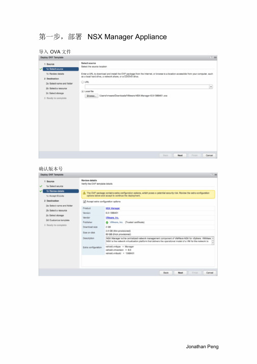
第一步,部署NSX Manager Appliance导入OVA文件确认版本号Jonathan Peng选择NSX Manager的管理端口组,与vCenter 通信使用。
确认EULA和选择部署的集群与存储后,对NSX Manager进行自定义,这里设置admin 密码和CLI 模式的密码。
VMware展开Network Properties ,填写NSX Manager主机名和配置管理的IPv4 地址与vcenter 通信使用展开DNS和Services Configuration ,配置DNS和域名,配置NTP服务器信息注意:NSX的时间同步必须要与vcenter 和esxi 主机一致,时间敏感!Jonathan Peng确认配置信息,并完成Appliance 部署。
VMware第二步,设置NSX Manager与vCenter 关联。
登陆https://172.20.21.3 ,使用admin 和设置好的密码登陆NSX Manager管理页面。
(可选)选择Manager Appliance Settings ,配置IP、NTP、主机名、DNS和备份恢复等信息。
Jonathan Peng选择Manage vCenter Registration 配置SSO和vCenter 信息,显示绿灯后NSX Manager配置完成。
VMware第三步,配置NSX虚拟网络稍等一会,重新登陆vCenter 主页(使用NSX注册vCenter SSO 和vCetner 服务的权限,如:administrator@vsphere.local ),会出现Networking&Security 控件和按钮,点击进入NSX管理页面。
Jonathan Peng1) 点击Installation ,可见NSX Manager信息,并按+添加首个Controller节点。
配置Controller 信息,包括创建IP Pool 用于Controller 使用,Connected To的端口组,以及IP Pool 地址是与NSX Manager通信使用。
NSX平台安装与管理指南

NSX平台安装与管理指南内容1.简介 (3)2.NSX平台安装部署 (3)2.1NSX Manager部署流程 (3)2.2NSX 组件部署流程 (11)3.NSX平台运行与配置 (21)3.1逻辑交换机(LSW) (21)3.2分布式逻辑路由器(DLR) (24)3.3边界服务网关(Edge) (30)3.4OSPF路由 (36)3.5NAT配置 (41)3.6分布式防火墙配置(DFW) (43)4.NSX平台管理与维护 (46)4.1系统变更 (47)4.2用户权限 (50)4.3系统监控 (52)4.4日志管理 (53)4.5配置备份与恢复 (54)附录 A: 参考 (56)1. 简介该指南为NSX平台及组件提供安装和配置步骤说明。
请注意:此文档仅提供安装样例,并尽最大努力反映客户的实际安装配置情况——如果需要查阅详细的配置参数信息,请参考《NSX 配置工作表》。
2. NSX平台安装部署该部分提供了VMware NSX的安装部署流程。
2.1 NSX Manager部署流程2.1.1 NSX Manager安装步骤1. 登陆VMware vSphere?Client?, 选择需要部署NSX Manager 的主机,点击菜单栏中的File > ImportDeploy OVF Template,导入VMware NSX Manager。
2. 选择NSX Manager Appliance安装包,点击下一步。
3. 在OVF模板详细信息页,点击下一步。
4. 在最终许可页,点击接受许可,并点击下一步。
5. 在名称和位置页面,填入合适的虚拟机名称,并选择相应文件加,点击下一步。
6. 在存储器页面,选择需要放置的存储位置,点击下一步。
7. 在磁盘格式页面,选择使用的磁盘格式,点击下一步。
8. 在网络映射页面,选择需要接入的管理网络端口组,点击下一步。
具体配置请参照《NSX配置工作表》。
9. 在属性页面,填入相应的信息,点击下一步。
vmware nsx实施方案

vmware nsx实施方案VMware NSX 实施方案VMware NSX 是一款用于软件定义数据中心和网络虚拟化的解决方案,它可以帮助企业实现网络和安全的自动化,提高 IT 灵活性和敏捷性,降低成本,同时增强安全性。
在实施 VMware NSX 时,需要考虑一些关键因素和步骤,以确保顺利完成部署并实现预期的效果。
首先,进行网络基础设施的评估。
在实施 VMware NSX 之前,需要对现有的网络基础设施进行全面的评估,包括网络拓扑、硬件设备、网络流量、安全策略等方面。
这将有助于确定是否需要进行网络重构以支持 NSX 的部署,并为后续的规划和设计工作提供重要参考。
其次,制定详细的实施计划。
在评估基础设施的基础上,制定详细的实施计划至关重要。
实施计划应当包括部署时间表、资源分配、风险评估、测试计划等内容,以确保实施过程有条不紊地进行,并最大程度地减少潜在的风险。
接下来,进行网络虚拟化的设计和部署。
在实施 VMware NSX 时,需要根据实际业务需求和网络环境特点进行网络虚拟化的设计和部署。
这包括逻辑网络的划分、网络隔离策略、安全组规则的定义等工作。
在设计和部署过程中,需要充分考虑网络性能、可靠性和安全性等方面的要求。
然后,进行安全策略的配置和管理。
VMware NSX 提供了丰富的安全功能,包括防火墙、安全组、安全策略等,可以帮助企业加强对网络流量的监控和管理。
在实施过程中,需要根据实际安全需求,配置和管理相应的安全策略,以保护企业网络免受各种安全威胁的侵害。
最后,进行性能优化和监控。
在实施 VMware NSX 后,需要进行性能优化和监控工作,以确保网络虚拟化的稳定性和高效性。
这包括对网络流量、带宽利用率、延迟等性能指标进行监控和分析,及时发现和解决潜在的性能问题,提高网络的整体运行效率。
综上所述,实施 VMware NSX 是一项复杂的工程,需要全面的规划和准备工作。
通过对网络基础设施的评估、制定详细的实施计划、进行网络虚拟化的设计和部署、配置和管理安全策略,以及进行性能优化和监控,可以帮助企业顺利实施 VMware NSX,并最大程度地发挥其在软件定义数据中心和网络虚拟化方面的优势。
- 1、下载文档前请自行甄别文档内容的完整性,平台不提供额外的编辑、内容补充、找答案等附加服务。
- 2、"仅部分预览"的文档,不可在线预览部分如存在完整性等问题,可反馈申请退款(可完整预览的文档不适用该条件!)。
- 3、如文档侵犯您的权益,请联系客服反馈,我们会尽快为您处理(人工客服工作时间:9:00-18:30)。
NSX for vSphere Getting Started GuideVMware NSX for vSphere, release 6.0.xJuly 21, 2014Table of ContentsNSX for vSphere Getting Started Guide (1)Introduction (3)Installation of NSX for vSphere (4)Infrastructure requirements for NSX-v (4)NSX-v Installation overview (6)Step 1: Install NSX Manager (6)Step 2: Install the NSX Controller Cluster (8)Step 3: Prepare ESXi hosts for NSX (10)L2 Logical Switching (14)Goal of the L2 logical switching lab (14)Create four Logical Switches (14)Add VMs on Web/App/DB Logical Switches (15)Validate that VMs on the same Logical Switch can communicate (16)Distributed Logical Routing (18)Goal of the logical routing lab (18)Create a single Distributed Logical Router (18)Validate that VMs in the different Logical Switches can communicate (21)Distributed Firewalling (23)Goal of the Distributed Firewalling lab (23)Create the Distributed Firewall rules (23)Validate the Distributed Firewall rules (25)Logical Centralized Routing (26)Goal of the Logical Centralized Routing lab (26)Create a single Logical Centralized Router (Edge) (27)Configure Dynamic Routing on Logical Distributed and Centralized Routers (29)Validate that dynamic routes are being learned (32)Validate communication from internal to Centralized Router external interface (33)Create many-to-one NAT (for traffic initiated from Web-Tier01 to external) (33)Validate communication from Web-Tier-01 to Internet (34)Logical Load Balancing (35)Goal of the Logical Load Balancing lab (35)Create one new Load Balancer (36)Configure the Load Balancer (37)Update the Distributed Firewall rules to allow Load Balancer-to-Web server communication (40)Validate that the Server Pool is UP (40)Create a one-to-one NAT rule on the External Edge Router (for traffic initiated from external to loadbalancer) (41)Check that external network hosts can communicate to VIP (42)Getting Help and More Information (43)NSX-v Documentation (43)Contacting the NSX Technical Services Team (43)NOTE: To obtain the latest information about NSX for vSphere, please visit/products/nsxIntroductionThis document provides step-by-step examples that demonstrate how to set up the following network services in NSX for vSphere:∙Logical Switches∙Logical Distributed Routers∙Distributed Firewalls∙Logical Centralized Routers (Edge)∙with Dynamic Routing∙with many-to-one NAT∙Logical Load Balancers (Edge)At the end, you’ll have the following logical network deployed in your lab:Figure 1 – Logical View of labL2 bridging, VPN, and service composer are not covered in this document. Likewise, integrations with third party vendors, such as Palo Alto Networks, Symantec and F5, are not covered here.Installation of NSX for vSphereThis section guides you through the step-by-step installation, configuration and validation of a new NSX for vSph ere (“NSX-v”) deployment.Infrastructure requirements for NSX-vVMware elements:Prior to installing NSX for vSphere, you must deploy:∙vCenter 5.5 with:∙one or more Compute clusters∙Management and Edge cluster∙two or more ESXi 5.5 in each clusterEach ESXi host has the following characteristics:∙Server hardware is listed on the VMware HCL for vSphere 5.5∙2x Quad Core x86_64 compatible CPUs with a speed of 2Ghz or greater, plus hardware-assisted virtualization support (total of 8 physical cores)∙32GB of RAM or greater∙2x Physical NICs∙Either 5GB of Local Disk/Dedicated boot from SAN LUN or supported ESXi embedded device (USB/SD). Local Disk is not required if vSphere Auto Deploy is used.Figure 2 – Infrastructure for NSXFor resource constraints, this lab uses only one Compute Cluster, as shown in the following screenshots.Network fabric:Configure at least 1600 byte of MTU frame sizes on all the physical switches/routers between ESXi.vCenter:Clusters:∙One Compute Cluster “Cluster-CompA” with two ESXi.∙One Mana gement + Edge Cluster “Cluster-Mgt_Edge” with two ESXi.Figure 3 – vCenter Host ViewNetworking:∙Virtual Standard Switch (vSS) for Cluster-CompA and Cluster-Mgt_Edge:∙Management: This vSS is used for the ESXi-Compute and ESXi-Mgt_Edge management.Interface to use: The interface of the ESXi in Cluster-CompA + Cluster-Mgt_Edge on theManagement network is used.∙Virtual Distributed Switch (vDS) for Cluster-CompA:∙vDS-CompA: This vDS will be used for the VM production traffic. Interface to use: The interface of the ESXi in Cluster-CompA on the Transport network is used. Note: No ESXi IP@ isconfigured yet.∙Virtual Distributed Switch (vDS) for Cluster-Mgt_Edge:∙vDS-Mgt_Edge: This vDS will be used for the VM production traffic. Interface to use: The interface of the ESXi in Cluster-Mgt_Edge on the Transport network is used. Note: No ESXi IP@ is configured yet. Note2: Create a Management Network for the future logical routers“LogicalRouter_Mgt”∙vDS-External: This vDS will be used to talk to the physical external network. Interface to use: The interface of the ESXi in Cluster-Mgt_Edge on the External network is used. Note: No ESXi IP@ is configured.Figure 4 – vCenter Networking ViewNSX-v Installation overviewIn this step, you’ll deploy the NSX Manager and NSX Controller Nodes:Figure 5 – NSX elementsStep 1: Install NSX ManagerThe NSX Manager is the centralized management component of NSX, and runs as a virtual appliance on an ESX host.1.Install NSX Manager: From vCenter Home-> Hosts and Clusters, select Cluster-Mgt_Edge andDeploy OVF TemplateFigure 6 – Installation NSX Manager2.Register NSX Manager with vCenter: Log in NSX Manager and from NSX Manager Manage ->NSX Management Services, register to vCenterFigure 7 – NSX Manager registration to vCenter3.Validate registration: Log out of vCenter if already logged in. And re-log in with root (required toget the NSX plugin installed in vCenter). Note: The first login can take a few minutes. After registration, you will see the Network & Security plugin in the Inventory:Figure 8 – NSX plugin in vCenterStep 2: Install the NSX Controller ClusterThe NSX Controller Cluster is a distributed state management system that controls virtual networks and overlay transport tunnels1.Install the first NSX Controller Node: From NSX Home -> Installation, add first NSX ControllerNode.Figure 9 – First NSX Controller Node installationThe IP Pool “NSX Controller Cluster” has been created with the following settings:Figure 10 – NSX Controller Cluster IP pool2.Validate the installation of first NSX Controller Node: The deployment of an NSX ControllerNode can take few minutes.Figure 11 – First NSX Controller Node deployedNote: In rare cases, the Controller takes too long install and is automatically deleted. In such cases, you can install a DHCP server in the Controller’s subnet to speed up its installation. That DHCP server can be configured with fake IP addresses since the Controller will still get its IP address from the NSX IP Pool.3.Install the second and third NSX Controller Nodes:Note: You can run with only one NSX Controller in a lab (not supported in a production setting), but this will render you unable to test Controller Node high-availability. For a productiondeployment or to test high-availability, you must install a total of three Controller Nodes.From NSX Home -> Installation, add second and third NSX Controller NodesFigure 12 – Second and third NSX Controller Nodes installation4.Validate installation of all three NSX Controller NodesFigure 13 –NSX Controller Cluster deployedStep 3: Prepare ESXi hosts for NSXTo provide all the NSX services, special kernel modules and user space tools have to be installed on the ESXi hosts.1.Install NSX elements on cluster hosts: From NSX Home -> Installation-> Host Preparation,click Install for all the clusters:Figure 14 –Installation of NSX elements on cluster hosts2.Check the installation of NSX elements on cluster hostsFigure 15 – Validation of installation of NSX elements on clusters hosts3.Configure the VXLAN VTEP interface for Cluster-CompA hosts: From NSX Home ->Installation-> Host Preparation, click Configure for the Cluster-CompA:Figure 16 – Configuration of VTEP interface for Cluster-CompA hostsFigure 17 – Configuration of VTEP IP@ pool for the Cluster-CompA hosts4.Validate the VTEP configuration on the Cluster-CompA hosts. Note: You may see an “ErrorUncon figure” message. This is a known display issue. Refresh the window to see the correct status.Figure 18 – Validation VTEP IP@ configuration for the Cluster-CompA hosts5.Configure the VXLAN VTEP interface for Cluster-Mgt_Edge hosts:Figure 19 – Configuration of VTEP interface for Cluster-Mgt_Edge hostsFigure 20 – Configuration of VTEP IP@ pool for the Cluster-Mgt_Edge hosts6.Validate the VTEP configuration on the Cluster-Mgt_Edge hosts. Note: You may see an “ErrorUnconfigure” message. This is a known display issue. Refresh the window to see the correct status.Figure 21 – Validation VTEP IP@ configuration for the Cluster-Mgt_Edge hosts7.View of the VTEP IP@ allocated to each Cluster hosts. From NSX Home -> Installation->Logical Network Preparation -> VXLAN Transport:Figure 22 – View of the VTEP IP@ allocated to each Cluster hosts8.Configure VXLAN Segment ID (VXLAN Network Identifier – VNI): From NSX Home ->Installation-> Logical Network Preparation -> Segment ID, click Edit. Note: Since NSX 6.0 with ESXi 5.5, multicast support is no longer required on the physical fabric.Figure 23 – View of the VTEP IP@ allocated to each Cluster hosts9.Configure a Transport Zone: The transport zone is the compute diameter of your cloud. You wantall your ESXi hosts to participate to your cloud. From NSX Home -> Installation-> LogicalNetwork Preparation -> Transport Zone, click +. Note: Since NSX 6.0 with ESXi 5.5, multicastsupport is no longer required on the physical fabric.Figure 24 – Creation of the Transport Zone that spans among all ClustersThis completes the installation of the NSX-v elements of your deployment. Proceed to the logical switch set-up steps in the next section.L2 Logical SwitchingGoal of the L2 logical switching labIn this section, you will create Logical Switches.Figure 25 – Logical View Logical SwitchesCreate four Logical SwitchesFrom NSX Home -> Logical Switches, create four Logical Switches called: ∙Transit-Network-01∙Web-Tier-01∙App-Tier-01∙DB-Tier-01Figure 26 –Logical Switch creationNote: You will notice that one vDS Port Group is automatically created for each Logical Switch. From vCenter Home -> NetworkingFigure 27 –vDS Port Groups created for each logical switchAdd VMs on Web/App/DB Logical SwitchesYou have VMs on the different Cluster-CompA hosts:Figure 28 – VMs in Cluste-CompAFrom NSX Home -> Logical Switches, add VMs to the appropriate logical switchFigure 29 – Add VMs onLlogical SwitchFigure 30 – Select VMsNote: You can check the VMs are connected to the correct Logical Switch on vCenter too: From vCenter Home -> Hosts and Clusters, look at the VM HardwareFigure 31 – Validate VM Network adapter is connected to vDS port groupValidate that VMs on the same Logical Switch can communicateFigure 32 – ping between Web VMsNote: The VM traffic flow in the fabric is:Figure 33 – Logical Switch traffic flowDistributed Logical RoutingGoal of the logical routing labIn this step, you’ll create a Distributed Logical Router.Figure 34 – Logical View Distributed Logical RouterCreate a single Distributed Logical RouterFrom NSX Home -> NSX Edges, create a Distributed Logical Router with four interfaces (LIFS) ∙Uplink to Transit-Network-01 with an IP of 172.16.1.2/29∙Internal connected to Web-Tier-01 Logical Switch with IP 10.0.1.1/24∙Internal connected to App-Tier-01 Logical Switch with IP 10.0.2.1/24∙Internal connected to DB-Tier-01 Logical Switch with IP 10.0.3.1/24Figure 35 – Logical Distributed Router creation, first paneFigure 36 – Logical Distributed Router creation, second paneFigure 37 – Logical Distributed Router creation, third paneNote: One Management Interface must be configured. This interface is to access the Logical Router Control VM via SSH for management/troubleshooting (t he VM production traffic doesn’t reac h the Logical Router Control VM - see Figure 39 and Figure 40). For SSH access, configure a management IP address (not shown in the screenshot above).Validate that VMs in the different Logical Switches can communicateFigure 38 – ping between Web and App VMNote: The Logical Router Control VM (in the Mgt_Edge Cluster) is not involved in the L3 VM traffic flow.The VM traffic flow in the fabric is shown below.Figure 39 – L3 traffic flow – case both VMs are in the same ESXi hostFigure 40 – L3 traffic flow – case both VMs are in different ESXi hostsDistributed FirewallingGoal of the Distributed Firewalling labIn this step, you’ll create the Distributed Firewall rules.Figure 41 – Logical View Distributed FirewallCreate the Distributed Firewall rulesFor ease of use, the example below is using Logical Switch Names for the “Source” and “Destination” instead of subnets.This option works only if you have the VM Tools installed on the VMs.If you do not have the VM Tools on your VMs, use subnet.From NSX Home -> Firewall, create the rules:1)External access: Source any, Destination Web-Tier-01, Allow https, Apply To Web-Tier-012)Inter Web-Tier-01: Source Web-Tier-01, Destination Web-Tier-01, Allow icmp + ssh + http, ApplyTo Web-Tier-013)Inter Web-Tier-01_block: Source Web-Tier-01, Destination Web-Tier-01, Block any, Apply To Web-Tier-014)Web-Tier-01-App-Tier-01: Source Web-Tier-01, Destination App-Tier-01, Allow icmp + http, ApplyTo Web-Tier-01 + App-Tier-015)Inter App-Tier-01: Source App-Tier-01, Destination App-Tier-01, Allow icmp + ssh + http, Apply ToApp-Tier-016)App-Tier-01-DB-Tier-01: Source App-Tier-01, Destination DB-Tier-01, Allow icmp + mysql, ApplyTo App-Tier-01 + DB-Tier-017)Web-Tier-01-External: Source Web-Tier-01, Destination any, Allow all, Apply To Web-Tier-018)Everything else: Source any, Destination any, Block any, Apply To Web-Tier-01 + App-Tier-01 +DB-Tier-01Note: To display the field “Apply To”, click on the grid:Figure 42 –Distributed Firewall fields selectionFigure 43 –Distributed Firewall rulesValidate the Distributed Firewall rulesFigure 44 – ping and ssh between Web and App VM Note: The non-authorized traffic is dropped at the beginning:Figure 45 – Distributed Firewall traffic flowLogical Centralized RoutingGoal of the Logical Centralized Routing labIn this step, you’ll create a Logical Centralized Router (Edge) with:∙dynamic routing∙many-to-one NATFigure 46 – Logical View Logical Centralized RouterCreate a single Logical Centralized Router (Edge)From NSX Home -> NSX Edges, create an Edge Service Gateway with two interfaces (LIFS) ∙Uplink to External with an IP of 20.20.20.2/24∙Internal to Transit-Network-01 with an IP of 172.16.1.1/29Figure 47 – Logical Centralized Router creation, first paneFigure 48 – Logical Centralized Router creation, third paneFigure 49 – Logical Centralized Router creation, fourth paneFigure 50 – Logical Centralized Router creation, fifth paneFigure 51 – Logical Centralized Router creation, sixth paneConfigure Dynamic Routing on Logical Distributed and Centralized RoutersDynamic routing configuration on Logical Distributed Router1)Enable Dynamic Routing:a)From NSX Home -> NSX Edges, select the Logical Distributed Router and navigate to Manage ->Routing -> Global Configuration, and click Edit Dynamic Routing Configuration.b)Accept the default Router ID and Publish change (don’t click “Enable OSPF” here because aProtocol Address needs to be defined first)Figure 52 – Logical Distributed Router Dynamic Routing configuration2)Enable OSPFa)Navigate to Manage -> Routing -> OSPF, click Edit:o Enable OSPF checkboxo Add a Protocol Address of 192.168.10.3o Forwarding Address of 192.168.10.2b)and Publish changeFigure 53 – Logical Distributed Router OSPF configuration3)Configure OSPFa)Navigate to Manage -> Routing -> OSPF, click Edit:b)Add a new Area Definition with the default values:Figure 54 – Logical Distributed Router OSPF area configuration4)Add the Area to Interface Transit-Uplink and Publish change:Figure 55 – Logical Distributed Router OSPF area interface configuration5)Validate Route Redistribution for connected networks is permitted:Figure 56 – Logical Distributed Router dynamic routing route redistributionDynamic routing configuration on Logical Centralized Router1)Enable Dynamic Routinga)From NSX Home -> NSX Edges, select the Logical Centralized Router and navigate to Manage ->Routing -> Global Configuration, Click Edit Dynamic Routing Configurationb)Accept the default Router ID and Publish change (don’t click “Enable OSPF” here because aProtocol Address needs to be defined first)Figure 57 – Logical Centralized Router Dynamic Routing configuration2)Configure OSPFa)Navigate to Manage -> Routing -> OSPF, click Edit:b)Add a new Area Definition with the default values:Figure 58 – Logical Centralized Router OSPF area configuration3)Add the Area to Interface Transit-Uplink and Publish change:Figure 59 – Logical Centralized Router OSPF area interface configuration 4)Add Route Redistribution for connected networks and static routes and Publish change:Figure 60 – Logical Centralized Router dynamic routing route redistribution Validate that dynamic routes are being learnedFigure 61 – OSPF status on Logical Distributed RouterFigure 62 – OSPF status on Logical Centralized RouterValidate communication from internal to Centralized Router external interfaceFigure 63 – Communication from web-01 to Centralized Router external interfaceCreate many-to-one NAT (for traffic initiated from Web-Tier01 to external)1)Add a NAT IP address to a Centralized Router external interface. From NSX Home -> NSX Edges,select the Centralized Distributed Router and navigate to Manage -> Settings -> Interfaces, Click Edit External interface and add IP address 20.20.20.3Figure 64 – NAT IP address on External interface2)Configure many-to-one NAT. Navigate to Manage -> NAT, Add DNAT and Publish change.Figure 65 – DNAT configuration for Web-Tier-01 subnetValidate communication from Web-Tier-01 to InternetFigure 66 – ping from Web VM to Internet Note: The VM traffic flow in the fabric is shown below:Figure 67 – Centralized Logical Router traffic flowLogical Load BalancingGoal of the Logical Load Balancing labIn this step, you’ll create a Logical Load Balancer (Edge) in one-arm mode.Figure 68 – Logical View Logical Load BalancerThe end-users access the VIP over https. The load balancer terminates https and talks to the servers over http.Create one new Load BalancerFrom NSX Home -> NSX Edges, create one Edge Service Gateway with one interface (LIF) Uplink to Web-Tier-01 with an IP of 10.0.1.5/24Figure 69 – Logical Distributer Router creation, first paneFigure 70 – Logical Distributer Router creation, third paneFigure 71 – Logical Distributer Router creation, fourth paneFigure 72 – Logical Distributer Router creation, fifth paneFigure 73 – Logical Distributer Router creation, sixth paneConfigure the Load Balancer1.Enable Load Balancinga.From NSX Home -> NSX Edges, select the Logical Load Balancer and navigate toManage -> Load Balancer -> Global Configuration, click Edit and enable load balancer.Figure 74 – Enable Load Balancing2.Create a self-signed certificate by navigateing to Manage -> Settings->Certificates, add a new self-signed certificate clicking on:a.Actions – Generate CSRFigure 75 – Certificate Signing Request (CSR)b.Actions – Self Sign CertificateFigure 76 – Self Signing Certificate3.Create an Application Profilea.Navigate to Manage -> Load Balancer -> Application Profiles, add a new ApplicationProfile with the following values:Figure 77 – Application Profile creation4.Create a Server Pool by navigating to Manage -> Load Balancer -> Pools, adding a new Pool withthe following values:Figure 78 – Server Pool creation5.Create VIP by navigating to Manage -> Load Balancer -> Virtual Servers, add a new VIP with thefollowing values:Figure 79 – VIP creationUpdate the Distributed Firewall rules to allow Load Balancer-to-Web server communicationFrom NSX Home -> Firewall, update the rule “Inter Web-Tier-01” with the IP@ of the Load Balancer 10.0.1.5:Note: You have to add the IP@ of the load balancer because the Edge doesn’t have the VM Tools.Figure 80 – Updated Distributed Firewall rulesValidate that the Server Pool is UPFrom NSX Home -> NSX Edges, select the Logical Load Balancer and navigate to Manage -> Load Balancer -> Pools, click Show Pool Statistics and validate the VIP is UPFigure 81 – Server Pool statusCreate a one-to-one NAT rule on the External Edge Router (for traffic initiated from external to load balancer)1.Add NAT IP address to Centralized Router external interfaceFrom NSX Home -> NSX Edges, select the Logical Centralized Router and navigate to Manage -> Settings -> Interfaces, click Edit External interface and add IP address 20.20.20.4Figure 82 – NAT IP address on External interface for VIP2.Configure one-to-one NAT:Navigate to Manage -> NAT, Add DNAT and Publish changeFigure 83 – DNAT configuration for VIPCheck that external network hosts can communicate to VIPFigure 84 – HTTPS access to VIP from externalBelow, we depict the VM traffic flow in the fabric.Figure 85 – Load Balancer traffic flowGetting Help and More InformationNSX-v DocumentationIn addition to this document, you can read the following documents for help setting up NSX-v. All are available from https:///support/pubs/nsx_pubs.html:∙NSX for vSphere Installation and Upgrade Guide∙NSX for vSphere Administration Guide∙NSX for vSphere API Reference Guide∙NSX for vSphere Command Line Interface ReferenceContacting the NSX Technical Services TeamYou can reach the NSX technical services team at /support.html.。