基于MCS51单片机步进电机的控制系统设计与实现
基于51单片机的步进电机控制系统设计
基于51单片机的步进电机控制系统设计中文摘要步进电机是一种受脉冲信号控制,并且能将脉冲信号转化为相应的角位移或者线位移的数字电动机。
由于步进电机具有步距误差不积累、运行可靠、结构简单、惯性小、成本低等优点,因此,被广泛使用于计算机外围电路、自动化控制装置以及其他的数字控制装置中,如打印机、钟表、数模转换设备等装置中。
随着科学技术的快速发展,相应的控制系统也产生了很多种类,步进电机的身影在众多领域中可以看到。
其中采用单片机作为控制核心的控制系统,由于其电路简单、成本低、可靠性强等优点,满足众多领域的需求,得到了大量的运用.因此,研究基于单片机的步进电机控制系统,具有重要的现实意义。
本设计研究的是基于51单片机对步进电机的控制系统。
通过单片机的I/O端口输出时序方波作为控制信号,信号经过芯片ULN2003驱动芯片驱动步进电机进行不同的指令进行工作。
根据不同的需要,通过按键电路来控制步进电机的启停、正反转和加减速等功能,并在数码管上实时显示步进电机的工作状态。
本文给出了电路各个模块的电路图,并用Proteus的ISIS软件对控制系统的各个功能进行了仿真,并给出了相应的仿真结果图像。
关键词:单片机;步进电机; 电机驱动; 控制系统AbstractStepper motor controlled by a pulse signal,and a pulse signal can be converted to the corresponding angular displacement or linear displacement of the digital motor。
As the stepper motor has a step error does not accumulate, reliable, simple structure,small inertia, low cost, and therefore,are widely used in computer peripheral circuits,automatic control devices and other digital control devices, such as printers,watches and clocks ,digital to analog conversion equipment,and other devices. With the rapid development of science and technology,the corresponding control system also produced many types of stepper motor figure can be seen in many areas. Which uses microcontroller as the control of the control system,because of its simple circuit, low cost,high reliability, etc。
MCS51单片机课程设计基于单片机的步进电机控制系统

MCS51单片机课程设计基于单片机的步进电机控制系统.txt我不奢望什么,只希望你以后的女人一个不如一个。
真怀念小时候啊,天热的时候我也可以像男人一样光膀子!本文由灰太狼科技贡献doc文档可能在WAP端浏览体验不佳。
建议您优先选择TXT,或下载源文件到本机查看。
数理与信息工程学院《单片机原理与应用》期末学期课程设计数理与信息工程学院《单片机原理及应用》期末学期课程设计单片机原理及应用》期末学期课程设计题目:基于单片机的步进电机控制系统专业:电子信息工程班级:电信 041 班姓名:学号:指导老师:指导老师:成绩:(2007.1)1数理与信息工程学院《单片机原理与应用》期末学期课程设计目第1章 1.1录............................................................................3 引言............................................................................3 步进电机控制系统概述. (3)1.2 本设计任务和主要内容............................................................4 第2章 2.1 2.2 系统主要硬件电路设计.......................................................... 系统主要硬件电路设计..........................................................5 硬件电路设计单片机控制系统原理.............................................................5 单片机主机系统电路 (5)2.2.1 时钟电路……………………………………………………………6 2.2.2 复位电路……………………………………………………………6 2.3 步进电机驱动电路…………………………………………………………7 2.4 第3章3.1 3.2 LED 显示电路…………………………………………………………….8 系统的软件设计…………………………………………………………10 系统的软件设计…………………………………………………………10 ..................................................................步进电机的位置控制............................................................10 显示子程序 (13)结束语……………………………………………………………………………………………………………………………………17 第四章结束语…………………………………………………………………17 参考文献…………………………………………………………………18 第 5 章参考文献…………………………………………………………………18 …………………………………………………………………2数理与信息工程学院《单片机原理与应用》期末学期课程设计基于单片机的步进电机控制系统第1章引言在当今社会的各个领域步进电机无处不在,应用领域涉及机器人、工业电子自动化设备、医疗器件、广告器材、舞台灯光设备、印刷设备、计算机外部应用设备等等。
基于51单片机的步进电机控制系统设计
基于51单片机的步进电机控制系统设计中文摘要步进电机是一种受脉冲信号控制,并且能将脉冲信号转化为相应的角位移或者线位移的数字电动机。
由于步进电机具有步距误差不积累、运行可靠、结构简单、惯性小、成本低等优点,因此,被广泛使用于计算机外围电路、自动化控制装置以及其他的数字控制装置中,如打印机、钟表、数模转换设备等装置中。
随着科学技术的快速发展,相应的控制系统也产生了很多种类,步进电机的身影在众多领域中可以看到。
其中采用单片机作为控制核心的控制系统,由于其电路简单、成本低、可靠性强等优点,满足众多领域的需求,得到了大量的运用。
因此,研究基于单片机的步进电机控制系统,具有重要的现实意义。
本设计研究的是基于51单片机对步进电机的控制系统。
通过单片机的I/O端口输出时序方波作为控制信号,信号经过芯片ULN2003驱动芯片驱动步进电机进行不同的指令进行工作。
根据不同的需要,通过按键电路来控制步进电机的启停、正反转和加减速等功能,并在数码管上实时显示步进电机的工作状态。
本文给出了电路各个模块的电路图,并用Proteus的ISIS软件对控制系统的各个功能进行了仿真,并给出了相应的仿真结果图像。
关键词:单片机;步进电机;电机驱动;控制系统AbstractStepper motor controlled by a pulse signal, and a pulse signal can be converted to the corresponding angular displacement or linear displacement of the digital motor. As the stepper motor has a step error does not accumulate, reliable, simple structure, small inertia, low cost, and therefore, are widely used in computer peripheral circuits, automatic control devices and other digital control devices, such as printers, watches and clocks , digital to analog conversion equipment, and other devices. With the rapid development of science and technology, the corresponding control system also produced many types of stepper motor figure can be seen in many areas. Which uses microcontroller as the control of the control system, because of its simple circuit, low cost, high reliability, etc., to meet the needs of many fields, we get a lot of use. Therefore, based on single-chip stepper motor control system has important practical design study is 51 single-chip stepper motor control system. As a control signal, the signal through the chip ULN2003 stepper motor drive to work through the microcontroller I / O port output timing square wave. Depending on the need, through the key circuit to control the start and stop, reversing and ramp functions such as stepper motors, stepper motors in real-time display and digital working condition. In this paper, the circuit diagram of each module, and with the ISIS Proteus software for each function control system simulation, and the simulation results are given corresponding image.Key words: microcontroller; stepper motor; motor drive; control system目录中文摘要 (I)Abstract (II)1 绪论 (1)步进电机及其发展过程 (1)步进电机在我国的应用及前景 (2)本设计的研究内容 (2)步进电机的性能指标及工作原理 (3)步进电机的特点 (3)步进电机的种类 (4)步进电机的主要性能指标 (4)步进电机的工作原理 (6)步进电机控制系统的原理 (7)2 总体方案设计 (9)设计思路的选择 (9)单片机芯片的选择 (11)驱动电机芯片的选择 (12)显示电路的选择 (12)步进电机的选择 (13)3 控制系统的硬件电路设计 (14)键盘控制电路 (14)单片机最小系统电路 (15)数码管显示电路 (16)步进电机的驱动电路 (17)步进电机的其他电路 (18)4 控制系统的软件设计 (19)主程序流程图 (19)读按键子程序流程图 (20)按键处理子程序流程图 (21)电机控制中断程序流程图 (22)5 仿真与测试 (24)仿真软件介绍 (24)仿真的操作步骤 (24)电路板的焊接 (25)电路板的测试 (25)6 结论与展望 (27)致谢 (29)参考文献 (30)附录:系统总体电路图 (31)系统仿真原理图 (31)PCB打印图 (32)原件清单 (32)程序 (33)1 绪论步进电机及其发展过程步进电机是一种受脉冲信号控制,并且能将脉冲信号转化为相应的角位移或者线位移的数字电动机。
基于51单片机的步进电机正反转可控设计与仿真
2020.19设计研发基于51单片机的步进电机正反转可控设计与仿真李建中(江苏省海门中等专业学校,江苏南通,226100)摘要:步进电机是伺服控制中的关键部件,对步进电机进行精确高效地控制,是实现精密运动、制造等的重要手段。
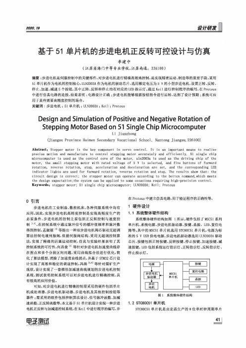
釆用51单片机作为电机的控制核心-ULN2003A作为电机的驱动芯片,选用额定电压为5V的小型步进电机,设置正转、反转、停止、加速、减速5个按钮,其中正转、反转和停止均有对应的LED指示灯。
通过Keil进行控制程序的编写,在Proteus 中进行仿真电路的连接,结果表明:电路设计正确;步进电机能够根据按钮指令进行运转,达到了设计预期;系统可应用于某些需要高精度控制的场合。
关键词:步进电机;51单片机;ULN2003A;Keil;ProteusDesign and Simulation of Positive and Negative Rotation ofStepping Motor Based on51Single Chip MicrocomputerLi Jianzhong(Jiangsu Province Haimen Secondary Vocational School,Narrtong Jiangsu,226100)Abst r act;St epper motor is the key compone n t in servo cont r ol.It is an import a n t means to realize precise motion and manufacture to control stepping motor accurately and efficiently.51single chip microcomputer is used as the cont r ol core of the mot o r,uln2003a is used as the driving chip of the motor,the small st e pping motor with:r ated volt a ge of5V is selec t ed,and five buttons of forward rotation,reverse rotation,stop,acceleration and deceleration are set,and the corresponding LED indicator lights are used for forward rotation,reverse rotation and stop.The resuIts show that:the circuit design is correct;the stepper motor can operate according to the button command,which meets the design expectation;the system can be applied to some occasions requiring high-precision control.Keywords:stepper motor;51single chip microcomputer;ULN2003A;Keil;Proteus0引言步进电机在工业制造、数控机床、各种伺服系统中均有应用。
基于51单片机控制步进电机毕业设计论文
基于51单片机控制步进电机毕业设计论文LTDesign of stepping motor control system based on single chip microcomputerAbstractStepping motor is a kind of by electric pulse signal to control actuator, because it is easy to control, small size and other characteristics, so in the CNC system, automatic production lines, automatic instrument, drawing machine and printer has a widely application. The popularization and application of microelectronic technology and rapid development of micro computer, and gradually into the application field of the motor, which makes before hardware circuit controller of large and complex can now be used software to achieve. This not only reduces the cost of hardware, but also improves the flexibility, reliability and functionality of the control. Because of the stepper motor with instantaneous start, rapid stop, high accuracy, and with the composition of the open loop system is simple, cheap, and very practical. Therefore, the design of based on single-chip stepper motor control system has great value and broad application.This paper mainly studies the design of the stepper motor system based on single chip microcomputer. The content of the subject includes the principle of step motor and single chip microcomputer, the stepper motor drive circuit is analyzed, and the system hardware circuit and program are designed and tested. The design of stepping motor control system adopts the method of software and hardware co simulation, which can effectively reduce the time and cost of the system development. Using Protues simulation software to complete the motor positive inversion, deceleration and stop start and other basic functions, using single chip microcomputer, stepping motor drive chip, character type LCD and keyboard array element module, the design of the controller and the driver for one step into the simulation of motor control system, realizes the function of the stepper motor range setting, position control and real-time display of a step into the working state of the motor. The hardware of the system consists of control circuit, display circuit, alarm feedback circuit and drive circuit, the corresponding software program is designed according to the hardware circuit, and the debugging and analysis are carried out. The design system has the characteristics of clear thinking, high reliability, strong stability and so on.Keywords: stepping motor ;drive circuit;single chip microcomputer;simulation and control system目录第一章绪论 (1)1.1课题背景 (1)1.2课题的目的和意义 (1)1.3课题的内容 (2)第二章步进电机的结构与特点 (3)2.1步进电机的构造 (3)2.2步进电机的工作原理 (4)2.3步进电机的主要特征 (5)2.4步进电机绕组的电气特性 (7)2.5步进电机的选型 (8)第三章设计原理分析 (9)3.1设计目的 (9)3.2设计要求 (9)3.3总体设计方框图 (10)3.4设计方案论证 (10)3.4.1系统控制方案 (10)3.4.2驱动模块方案选择 (13)3.4.3最终方案确定 (15)第四章步进电机控制系统硬件设计 (15)4.1单片机最小系统 (15)4.2 控制电路 (17)4.3 驱动电路 (19)4.4 显示电路 (20)4.5 位移越界报警电路 (21)4.6 状态指示灯显示电路 (22)第五章步进电机控制系统软件设计 (23)5.1主程序设计 (23)5.2 LCD显示程序设计 (25)5.3转速控制程序设计 (27)5.4程序设计 (28)5.5角度设定程序设计 (29)5.6位移设定程序设计 (31)第六章仿真结果与分析 (34)6.1整体硬件设计图 (34)6.2测试 (34)6.3误差分析 (39)第七章总结 (40)参考文献 (42)致谢 (45)第一章绪论1.1课题背景步进电机作为控制执行器,广泛应用于各种控制领域[1]。
基于51单片机的步进电机控制

目录第1章总体设计方案 (1)1.1设计原理 (1)1.2设计思路 (1)1.3实验环境 (2)第2章详细设计方案 (3)2.1硬件电路设计 (3)2.2主程序设计 (4)2.3功能模块的设计与实现 (5)第3章结果测试及分析 (8)3.1结果测试 (8)3.2结果分析 (8)参考文献 (9)附录A (10)附录B(电路原理图) (15)附录C (元件列表) (16)第1章总体设计方案1.1 设计原理根据课程设计任务书的内容与要求,要实现步进电机的工作过程,步进电机是一种将电脉冲转换成相应角位移或线位移的电磁机械装置,也是一种能把输出位移增量和输入数字脉冲对应的驱动器件。
首先要给步进电机送入脉冲信号来启动,然后在已经设定好的步进电机的正反转及三种节拍工作方式中切换,步进电机的三种节拍工作方式分别为单四拍、双四拍、单双八拍。
步进电机的驱动需要时钟脉冲信号,改变单片机输出脉冲信号来实现的。
改变各脉冲的先后顺序,可以改变电机的旋转方向和工作方式。
步进电机工作方式的转换则通过键盘控制,可以进行启动、停止、正转、反转及三种节拍工作方式的选择。
键盘的控制是在程序中已经给给每个键设置相应的功能,扫描键盘判断是否有键按下,若有,则执行与之对应的功能;若没有键按下,则保持正在运行的状态不变。
1.2 设计思路采用C语言程序设计的方法结合硬件电路设计方法,利用Lab6000实验箱上已有芯片来实现步进电机的工作(包括正转、反转、单四拍、双四拍、单双八拍的节拍工作方式)。
1)提出方案首先,实现步进电机的启动与停止;其次,实现步进电机的正反转;再次,实现在正转时可选择三种节拍工作方式;最后,实现在反转时可选择三种节拍工作方式。
2)方案论证P1口接步进电机的A~D口,键盘接通片选信号,扫描键盘,由于本程序设定固定按键为功能键,所以扫描键盘时,将使用到的按键的相应列扫描码设置为低电平,如果有键按下,74LS374输出的低电平经过按键被接到74LS245的端口上,这样从74LS245读回的数据就会有低位,根据74LS374输出的列信号和74LS245读回的行信号,就可以判断哪个键被按下。
基于51单片机的步进电机控制系统设计

基于51单片机的步进电机控制系统设计步进电机是一种特殊的直流电动机,具有定角度、定位置、高精度等特点,在许多领域得到广泛应用,如机械装置、仪器设备、医疗设备等。
本文将基于51单片机设计一个步进电机控制系统,主要包括硬件设计和软件设计两部分。
一、硬件设计步进电机控制系统的硬件设计主要包括51单片机、外部电源、步进电机驱动模块、以及其他辅助电路。
1.51单片机选择由于步进电机控制需要执行复杂的算法和时序控制,所以需要一个性能较高的单片机。
本设计选择51单片机作为主控芯片,因为51单片机具有丰富的外设接口、强大的计算能力和丰富的资源。
2.外部电源步进电机需要较高的电流供给,因此外部电源选择稳定的直流电源,能够提供足够的电流供电。
电源电压和电流的大小需要根据具体的步进电机来确定。
3.步进电机驱动模块步进电机驱动模块是连接步进电机和51单片机的关键部分,它负责将51单片机输出的脉冲信号转化为对步进电机的驱动信号,控制步进电机准确转动。
常用的步进电机驱动芯片有L297、ULN2003等。
4.其他辅助电路为了保证步进电机控制系统的稳定运行,还需要一些辅助电路,如限流电路、电源滤波电路、保护电路等。
这些电路的设计需要根据具体的应用来确定。
二、软件设计1.系统初始化系统初始化主要包括对51单片机进行外部中断、定时器、串口和IO 口等初始化设置。
根据实际需求还可以进行其他模块的初始化设置。
2.步进电机驱动程序步进电机的驱动程序主要通过脉冲信号来控制电机的转动。
脉冲信号的频率和脉冲宽度决定了电机的转速和运行方向。
脉冲信号可以通过定时器产生,也可以通过外部中断产生。
3.运动控制算法步进电机的运动控制可以采用开环控制或闭环控制。
开环控制简单,但无法保证运动的准确性和稳定性;闭环控制通过对电机转动的反馈信号进行处理来调整脉冲信号的生成,从而实现精确的运动控制。
4.其他功能设计根据具体的应用需求,可以加入其他功能设计,如速度控制、位置控制、加速度控制等。
基于51单片机实现的步进机控制系统设计

摘要步进电机是一种进行精确步进运动的机电执行元件,它广泛地用于工业机械的数字控制。
为使系统的可靠性,通用性,可维护性以及性价比最优,根据控制系统功能要求及步进电动机应用环境,确定了设计系统硬件和软件的功能划分,从而实现了基于8051单片机的四相步进电动机的开环控制系统。
控制系统通过单片机存储器、I/O口、中断、键盘、LED显示器的扩展,步进电动机的环形分配器、驱动及保护电路、人机接口电路、中断系统及复位电路、单电压驱动电路等的设计。
实现了四相步进电动机的正反转、急停等功能。
为实现单片机控制步进电动机系统在数控机床上的特殊应用,系统设计了两个外部中断,以实现步进电动机在某段时间内的反复正反转功能,也即数控机床的刀架自动进给运动。
关键词:8051单片机;四相步进电动机;控制Realizes based on single chip microcomputer 51 the stepping motor the control systemABSTRACTThe stepping motor is a precision electromechanical incremental actuator.It widely uses the digital approach for control of industrial machines.For dependable,in general use that make system,can support sex an sex price ratio superior,divide the line according to control system funcion request and a function for entering electricmotor applying environment,making sure designing system hardware with softwares, from but realizes to base on single chip microcomputer 8051 of four mutually the step enters the dynamoelectric opening the wreath the control the system.The control system passes the single saving maching,I/O in a machine, break off,the keyboard, the display of LED expands, a wreah for entering elecreic motor form assigns the machine,drive and the design of its protection electric circuit, man-machine connection electric circuit,interrupt system and reset circuit, single-voltage driver circuit and so on,realizes four mutually the step enters the electric motor positive and negative to turn, nasty stop to wait the function.For realizing single chip microcomputer control a special application for entering electric motor system in severalth contorling machine bed, the system designed two exteriors breaks off,toing realize a the step enters electric motor is in a certain time of again and again positive and negative turn the function, also count namely the knife that control the machine bed is automatic to enter to the sport.KEYWORD:single chip microcomputer 8051;four-phase stepper motor ;control第一章绪论1.1 课题背景当今社会,电动机在工农业生产、人们日常生活中起着十分重要的作用。
- 1、下载文档前请自行甄别文档内容的完整性,平台不提供额外的编辑、内容补充、找答案等附加服务。
- 2、"仅部分预览"的文档,不可在线预览部分如存在完整性等问题,可反馈申请退款(可完整预览的文档不适用该条件!)。
- 3、如文档侵犯您的权益,请联系客服反馈,我们会尽快为您处理(人工客服工作时间:9:00-18:30)。
学校代码:11509学号:1005073029Hefei University毕业设计(论文)BACH ELOR DISSERTATI ON论文题目:基于MCS51单片机步进电机的控制系统设计与实现学位类别:工学学士学科专业: 10级自动化2班作者姓名:导师姓名:完成时间: 2014年5月12日基于MCS51单片机步进电机的控制系统设计与实现中文摘要步进电机最早出现在十九世纪初期,经过一段时期的发展步进电机被广泛应用在各个领域,因为其具有良好的控制作用。
所以对步进电机控系统进一步的探索有着更为深远的意义。
本设计是基于单片步进电机的控制系统,硬件设计采用STC89C52单片机为控制核心;选取ULN2003作为驱动器提供脉冲频率,驱动步进电机运转;通过键盘的加减速按钮、正反转按钮和停止按钮来控制步进电机的速度、方向和停止,最后通过测试传感器将这几个参数显示在12864液晶显示器上。
软件设计采用KEIL软件工具进行C语言编写,通过各个模块端口的定义,编写出了步进电机加减速控制和正反转的程序,最后通过各模块程序调试对硬件电路施行控制。
本设计以经济实用为原则,通过软硬件结合的设计,实现了对步进电机转动速度和方向的有效控制。
该系统具有控制性好,设计成本低等优点。
关键字:STC89C52;步进电机;控制系统;测速传感器Stepper motor control system design and implementation based onMCS51 microcontrollerABSTRACTThe stepping motor was invented in the early 1800s, after a long period of development of the stepper motor is widely used in various fields, because it has good control effect. Therefore, the study of the stepper motor control system has a very important significance.This design is stepper motor control system based microcomputer, hardware design uses STC89C52 microcontroller as the control core; select ULN2003 as driver provides pulse frequency drive stepper motor rotation; through acceleration and deceleration button keyboard,forward and reverse button and stop buttons to control the stepper motor speed, direction and stops, Then these several parameters was displayed on the LCD monitor 12864 by the speed sensor. Software design using KEIL software tools for C language, defined each module port, and write a stepper motor control acceleration and deceleration and reversing the process. finally to control the hardware circuit through debugging.The design principle of economical and practical, through combination of software and hardware designed to achieve the effective control of the stepper motor rotation speed and direction. The system has good controllability and low coat.Keywords: STC89C52; stepper motor; control systems; speed sensor目录第一章绪论 (1)1.1课题背景 (1)1.2课题研究的目的及意义 (2)1.3系统设计的主要任务 (2)第二章总体方案设计 (3)2.1系统总体设计与分析 (3)2.2各模块功能说明 (3)2.3本章小结 (4)第三章控制系统硬件分析与设计 (5)3.1.中央处理器模块 (5)3.1.1单片机 (5)3.1.2复位电路 (7)3.1.3振荡电路 (8)3.2显示模块 (8)3.3驱动模块 (9)3.3.1步进电机 (10)3.3.2 ULN2003 (11)3.4电源模块 (12)3.5键盘模块 (12)3.6本章小结 (13)第四章控制系统软件分析与设计 (14)4.1 主程序流程图 (14)4.2 12864显示程序流程图 (15)4.3正反转程序流程图 (16)4.4加减速程序流程图 (17)4.5本章小结 (17)第五章系统的测试与结果分析 (18)5.1软件测试工具 (18)5.2测试数据与分析 (19)5.2.1圈数测试 (19)5.2.2速度测试 (19)5.3本章小结 (21)第六章毕业设计总结 (22)参考文献 (23)致谢 (24)附录 (25)附录一系统电路仿真图 (25)附录二系统实物图 (26)附录三单片机端口分配表 (27)附录四系统程序 (28)第一章绪论本章简单的介绍了步进电机的发展史,步进电机在各个领域的应用。
论述了研究本课题的目的和意义,最后简要的叙述了本设计控制系统需要完成的几项任务。
1.1课题背景在21世纪,电动机在我们社会中扮演着十分重要的角色,无论在工业、农业还是在我们日常生活中起着重要的作用。
步进电机是一种特殊的可以控制的电动机,在现代社会的额各个领域有着广泛的应用。
因为步进电机具有良好的控制作用,而且是当今机械电子工程的主要构件之一。
因此步进电机大量地使用在各类不同的自动化设备及控制装置等领域 [1]。
早期的步进电机大约出现在十九世纪三十年代左右,在通电的情况下,有一种能够自由旋转的电磁铁,就是我们所说的早期步进电机,其工作原理和现在的步进电机本质上是相同的[2]。
到了上世纪初,由于出现大规模的战争,军工业和造船业等重工业的快速发展,步进电机的需求量被无线放大。
同时期的西方报纸和期刊先后刊登了大量步进电机在军工业和造船业上应用的文章,那是的文章已经详细的介绍了不进电机电的设计方法和计算等。
在后来的一段时期这些理论被用于实践指导步进电机的结构设计和批量的生产[3]。
到了二十世纪八十年代后,步进电动机的控制方式开始变得更加多样化,主要原因是多用途模式的步进电机的产生。
在微电子个计算机技术高速发展的情况下,直接引起了对步进电机的使用数量成爆炸式增长,在各国家的军事领域和国民经济领域都有着广泛的应用。
步进电机实际上是一种将电脉冲转化为角位移的控制元件,它突出的优点是自身构造简单,具有快速的启动、停止和反转响应,运行安全可靠。
步进电机还有一些非常特殊的地方,它的步距值不会随着现场温度和电压的变化而改变,同时误差亦不会长时间积累,所以给实践的操作中带来了很大的方便[4]。
步进电机大量使用在各类产品中,其中消费类产品包括打印机和照相机等;工业产品包括机器人、数字控制体系和纸带传送机构等。
因此对步进电机的详细研究具有十分重要的意义。
本文设计了一种以STC89C52单片机为核心元件的控制系统。
1.2课题研究的目的及意义随着现代工业和农业的不断发展壮大,步进电机的使用量也成爆炸式增长。
以前的步进电机的控制精度和控制效果已无法达到当今社会生产力的要求,因此如何更好的发展和应用步进电机是非常值得思考的。
本课题的设计就是对步进电机进行控制,其本身就具有一些突出的优点是快速的起动、停止和反转响应;由于其采用开环控制,从而自身构造更加简易化并且成本低[5]。
在微电子个计算机技术高速发展的情况下,步进电机也朝着小型化矩形化发展以适应当前各种设备的需要,所以本课题对于步进电机控制的研究具有十分重要的意义。
1.3系统设计的主要任务设计的该控制系统应完成以下几项任务:(1)步进电机的启动和停止控制;(2)步进电机的加速和减速控制;(3)步进电机的正反转控制;(4)步进电机的转速动态显示在液晶显示器上。
第二章总体方案设计2.1系统总体设计与分析本设计是使用STC89C52为控制元件,设计出一种基于单片机步进电机的控制系统。
该控制系统通过自有的键盘模块来实现对步进电机的运转进行有效的控制,并且将步进电机的转速显示在液晶显示器上,转动方向以文字的形式显示在液晶显示器上。
下图是系统总体结构框图。
图1 系统总体结构框图2.2各模块功能说明本设计控制系统有五个模块:中央处理器模块、12864液晶显示模块、步进电机驱动模块、电源模块和键盘模块。
(1)中央处理器模块主要由振荡电路和复位电路构成。
振荡电路是给最小系统模块提供给频率,单片机的运行速度就是一该频率为基准的,频率高单片机运行速度快。
复位电路就是系统运行时在受到外部干扰,内部程序运行出错时,通过按下复位按钮可以让原程序重新开始运行,保证了单片机的正常启动[6]。
(2)本设计的显示模块采用12864液晶器来动态显示步进电机的转动速度和方向。
(3)本世纪的进电机驱动模块选用驱动器ULN2003为步进电机提供电脉冲信号,进而驱动步进电机转动。
ULN2003的输入端与单片机的P1口相连。
(4)电源模块是通过整流桥将变压器降压过来的交流电压转化为直流5V 供给其他四个模块。
(5)本设计的键盘模块包括了控制方向按钮键、加速按钮键、减速按钮键和启停按钮键,与单片机的P3口相连,通过这些键盘按钮可以对步进电机的转动状态进行有效的控制。
2.3本章小结本章首先简单的说明了该设计的思想,在控制低成本,且能完成该设计的情况下,通过综合考虑用了以STC89C52单片机作为本设计系统的控制核心元件。
第三章控制系统硬件分析与设计3.1.中央处理器模块中央处理器系统就是用最少的电子元件搭建的单片机而且能够正常工作的系统,其最小系统包括了单片机,复位电路、振荡电路和外部扩展等部分组成。