微型压力传感器PLD204D-10技术资料
WPD-102 压力传感器说明手册说明书

WARNING Ensure that the maximum individual port pressure doesnot exceed the maximum pressure range of the unit. For example, the maximum individual port pressure on a WPD-102 is 100 PSI. Exceed-ing this may damage the sensors and WILL give erroneous readings.WARNING Do not use in an explosive or hazardous environment, with combustible or flammable gasses, as a safety or emergency stop device or in any other application where failure of the product could result in personal injury. Use electrostatic discharge precautions during installation and do not exceed the device ratings.MOUNTING The transmitter mounts on a vertical surface with the pressure ports and cable entrance on the bottom using the two screw holes on the base of the unit. Ensure there is enough space around the unit to make the pressure and electrical connections. Avoid locations with severe vibrations or excessive moisture. The enclosure has a standard ½” conduit opening and may be installed with either a conduit coupler or a cable gland type fitting. In this position the High port is on the left and the Low port is on the right as shown on the pcb.WIRING Use 22 awg shielded wiring for all connections and do not locate the device wires in the same conduit with wiring used to supply induc-tive loads such as motors. Disconnect the power supply before making any connections to prevent electrical shock or equipment damage. Make all connec-tions in accordance with national and local electrical codes.This device is a 3-wire sourcing type transmitter. Connect the positive dc voltage or the hot side of the ac voltage to the terminal marked PWR . The power supply common is connected to the terminal marked COM . The device is reverse voltage protected and will not operate if connected backwards. The analog output signal is available on the OUT terminal. This signal is jumper selectable for either voltage or 4-20 mA output. In voltage mode, either 0-5 or 0-10 Vdc can also be selected. These options are indicated on the circuit board.The remote zero feature may be used by wiring a dry-contact (relay only) digital output to the ZERO terminals. Do not apply voltage to the ZERO terminals.PLUMBING The two pressure ports are labeled High and Low . The out-put signal indicates a positive value when the pressure is higher on the High port than the Low port so ensure these ports are connected correctly. Use an appropriately rated pressure tubing and arrange it to minimize stress on the connections.Do not allow material to fall into the pressure ports as contamination could damage the sensors.CONFIGURATION As shown on the pcb drawing, push-on jumpers and switches are used to select the output signal type, the input pressure range and several features. The device is factory configured to operate in the 4-20 mA output mode but can be changed to voltage mode by moving the two jumpersfrom the positions marked Current to the positions marked Voltage . Always note the current jumper position first and then move them to the new position.If the jumpers are rotated 90 degrees and installed incorrectly the product will not work and damage may occur. In voltage mode the output scale may be changed to either 0-5 or 0-10 Vdc by moving the single jumper to the 5V or 10V position.The Range and Options switches can be changed while the unit is operating. However, the output jumpers can only be changed while the power is removed.The jumper marked Light is for the LCD back-light option. The back-light is enabled in the On position but can be set to Off to reduce power consumption. The input pressure range (as shown on the product label) is set by moving the 4-position slide switch marked RANGE .Bidirectional operation, port swap, slow damping and analog reverse functions are available by switching the appropriate DIP switch position to ON.BIDIRECTIONAL This switch changes the range from 0 to full scale differ-ential pressure to minus full scale to plus full scale differential pressure. The analog output will read ½ when the differential pressure is zero. The example below shows the results when a Model 2 (0 to 100 psi) is operated in bidirec-tional mode (-100 to 100 psi).PORT SWAP This switch reverses the polarity of the pressure ports. It makes the HIGH port “low” and the LOW port “high”. This is useful to correct plumbing errors.SLOW DAMPING This switch provides an 8-second averaging for surge dampening (normally it is 4-seconds).OUTPUT REVERSE This switch reverses the output signal polarity. In reverse mode the analog output is maximum when the pressure differential is zero and decreases as pressure increases.OPERATION For normal operation such as 0-100 PSI, the pressure applied to the High port must be higher than the pressure applied to the Low port. If the pressure connection is reversed then the transmitter will always output 4 mA or 0 V. If the Low port is left open to ambient pressure, then the High port is used to measure a positive pressure and 0 PSI = 4 mA and 100 PSI = 20 mA.Model 1 2 3 4 101 50 PSI 25 PSI 10 PSI 5 PSI 102 100 PSI 50 PSI 20 PSI 10 PSI 103 200 PSI 100 PSI 40 PSI 20 PSI 104 500 PSI 250 PSI 100 PSI 50 PSI 105 5.0 Bar 2.5 Bar 1.0 Bar 0.5 Bar 106 7.50 Bar 3.75 Bar 1.50 Bar 0.75 Bar 107 10 Bar 5 Bar 2 Bar 1 Bar 108 30 Bar 15 Bar 6 Bar 3 Bar 109 500 kPa 250 kPa 100 kPa 50 kPa 110 750 kPa 375 kPa 150 kPa 75 kPa 111 1000 kPa 500 kPa 200 kPa 100 kPa 1123000 kPa1500 kPa600 kPa300 kPaPressure Range Wet-WetDifferential Pressure TransducerInstallation InstructionsHIGH port LOW port LCD 4-20 mA 0-5 V 100 PSI 50 PSI 50 PSI 16 mA 3.75 V 50 PSI 100 PSI -50 PSI 8 mA 1.25 V 50 PSI 50 PSI 0 PSI 12 mA 2.5 V 100 PSI0 PSI100 PSI20 mA5 VFor bidirectional operation such as +/-100 PSI, the pressure applied to the High port should be higher than the pressure applied to the Low port for a positive output response. Negative pressure is indicated if the High pressure is less than the Low pressure. In this case –100 PSI = 4 mA and +100 PSI = 20 mA. Since the transmitter is linear 0 PSI = 12 mA.CALIBRATION With both ports open to the ambient pressure (or with both ports equalized at 0 pressure), press and hold the auto-zero button or provide contact closure on the ZERO terminals for at least 3 seconds. Release the button or terminals and the device will calculate and store the new zero point. To protect the unit from accidental zeroing this feature is enabled only when the detected pressure on both ports is less than 5% of the full range. It is not recommended that the span calibration be performed in the field unless a high quality calibrator is available. SPECIFICATIONSMedia compatibility 17-4 PH stainless steel Input power 15 to 30 Vdc / 24 Vac nominal Supply current @ 24 Vdc 100 mA with LCD backlight 35 mA with backlight disabledOutput signal 4-20 mA, 0-5 or 0-10 Vdc Proof pressure Max. 2x F.S. range Burst pressure Max. 5x F.S. range Accuracy +/-1 %F.S. (range 4 is +/- 2 %) Surge damping 4 sec averaging (8 sec for slow) Long term stability +/-0.25% typical (1 year) Auto-zero adjust pushbutton and remote input Sensor operating range -40 to 105 °C (-40 to 220 °F) Operating environment 0 to 50 °C, 10 to 90 %RH n.c. Fittings 1/8” NPT femaleEnclosure 5” x 5” x 2.25” PVC NEMA 4Optional switch settings. Default is Normal (switch set to off).Power in, 24Vac/dc Common is shared with outputOutput, Current or Voltage.Common is shared with power supplyNOTE: The range and options switch can be changed while the unit is powered. However, the output jumpers can only be changed while the unit is unpowered.DO NOT CONNECT POWER TO THE ‘OUT’ TERMINAL AS THE UNIT WILL BE DAMAGED!REV. 006 10/2008WARNING Ensure that the maximum individual port pressure does not exceed the maximum pressure range of the unit. For example, the maximum individual port pressure on a WPD-102 is 100 PSI. Exceeding this may damage the sensors and WILL give erroneous readings.BOARD LAYOUT WIRINGJUMPER SETTINGSDisplay backlight on Display backlight off4-20 mA output 0-10 Vdc output 0-5 Vdc outputNOTE: The current/voltage output jumpers must be oriented as they are shown in the above illustration.。
MINI SMD 数字 AD 型热释电红外传感器 使用说明书

MINI SMD 数字AD 型热释电红外传感器Mini SMD AD Pyroelectric Infrared SensorsS22-P330Y 使用说明书V1.3森霸传感科技股份有限公司Senba Sensing Technology Co.,Ltd.森霸传感科技股份有限公司1.企业及产品概况:1.1体系认证●ISO14001认证公司获得ISO14001认证,在遵守国家环保法的基础上,通过采取各种改进措施,实现企业可持续性发展。
●ISO 9001认证公司获得国际标准化机构(ISO)的品质保证标准-即“ISO 9001”的认证。
1.2关于欧盟ROHS指令ROHS指令:欧盟提出的“关于在电子电气设备中限制使用某些有害物质的指令2011/65/EC”,公司生产的所有产品均符合欧盟ROHS指令。
1.3产品型号及检测原理1.3.1产品规格型号:本产品为SMD 数字AD 型双元热释电红外传感器,产品型号为S22-P330Y ,版本号为V1.3,若使用产品超出了产品列举的应用范围,请及时咨询产品应用或销售工程师。
1.3.2产品探测原理:传感器核心部件由热释电探测敏感元、红外滤光片和芯片IC三部分组成,其中探测敏感元为双元结构。
产品是将AD芯片与人体探测敏感元都集成在电磁屏蔽罩内的热释电红外传感器。
人体探测敏感元将感应到的人体移动信号传输到AD芯片上,其通过采集、滤波等输出16位数字信号,并通过外围电路的单片机实现相关功能。
2.非商业用途说明森霸传感科技股份有限公司(以下简称森霸)免费授权用户非商业性使用本产品说明书,并为用户提供产品变更和咨询服务。
若要进行商业性的销售、复制、散发或其他商业活动,须事先获取森霸的书面授权和许可。
另外,用户在使用本产品说明书时,不得违反法律、危害公共安全或损害第三方合法权益,森霸不承担由此引发的任何索赔责任。
3.产品说明3.1产品命名规则示例S:贴片型22:产品分类P:窗口:窗口尺寸4*43:感应单元:敏感元为双元结构3:脚位:功能脚位数量为30:红外滤光片:探测波长5-14um Y:芯片:表示其型号代码为YS22—P33Y森霸传感科技股份有限公司3.2产品特点⏹小型化⏹SMD回流焊贴装工艺⏹16位数字信号输出⏹单线串行数据⏹低电压、微功耗⏹适合超薄的产品外观设计3.3产品应用领域消费电子应用:⏹玩具⏹数码相框、门铃⏹电视机、冰箱、空调智能家居、安防应用:⏹USB报警器⏹入侵检测⏹网络摄像机⏹局域网监控器⏹私人警报器⏹汽车防盗系统灯饰应用:⏹室内、庭院、走廊、楼梯灯等的自动亮起和熄灯等3.4产品及推荐的焊盘尺寸图推荐焊盘尺寸图注:1、传感器双元结构,以X 向做左右横切运动时,其感应视角最大且探测距离最远。
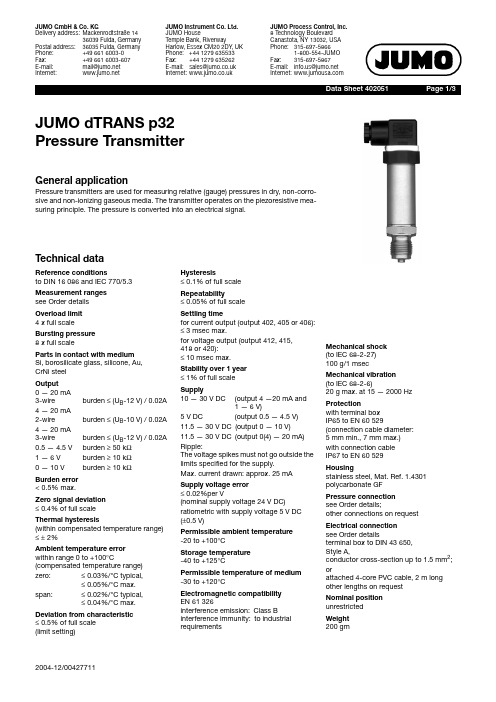
JUMO dTRAN S 压力传感器说明书

Data S heet 402051Page 1/3 JUMO dTRAN S p32Pre ss ure Tran s mitterG eneral applicationPressure transmitters are used for measuring relative (gauge) pressures in dry, non-corro-sive and non-ionizing gaseous media. The transmitter operates on the piezoresistive mea-suring principle. The pressure is converted into an electrical signal.Technical dataReference condition sto DIN 16086 and IEC 770/5.3Mea s urement range ssee Order detailsOverload limit4 x full scaleBur s ting pre ss ure8 x full scalePart s in contact with mediumSi, borosilicate glass, silicone, Au,CrNi steelOutput0—20mA3-wire burden ≤ (U B-12V) / 0.02A 4—20mA2-wire burden ≤ (U B-10V) / 0.02A 4—20mA3-wire burden ≤ (U B-12V) / 0.02A 0.5—4.5V burden ≥ 50kΩ1—6V burden ≥ 10kΩ0—10V burden ≥ 10kΩBurden error< 0.5% max.Zero s ignal deviation≤ 0.4% of full scaleThermal hy s tere s i s(within compensated temperature range)≤± 2%Ambient temperature errorwithin range 0to+100°C (compensated temperature range) zero:≤ 0.03%/°C typical,≤ 0.05%/°C max.span:≤ 0.02%/°C typical,≤ 0.04%/°C max. Deviation from characteri s tic≤ 0.5% of full scale(limit setting)Hy s tere s i s≤ 0.1% of full scaleRepeatability≤ 0.05% of full scaleS ettling timefor current output (output 402, 405 or 406):≤ 3msec max.for voltage output (output 412, 415,418 or 420):≤ 10msec max.S tability over 1 year≤ 1% of full scaleS upply10—30V DC(output 4—20mA and1—6V)5V DC (output0.5—4.5V)11.5—30V DC(output 0—10V)11.5—30V DC(output 0(4)—20mA)Ripple:The voltage spikes must not go outside thelimits specified for the supply.Max. current drawn: approx. 25mAS upply voltage error≤ 0.02%per V(nominal supply voltage 24V DC)ratiometric with supply voltage 5V DC(±0.5V)Permi ss ible ambient temperature-20to+100°CS torage temperature-40to+125°CPermi ss ible temperature of medium-30to+120°CElectromagnetic compatibilityEN 61 326interference emission:Class Binterference immunity:to industrialrequirementsMechanical s hoc k(to IEC 68-2-27)100g/1msecMechanical vibration(to IEC 68-2-6)20g max. at 15—2000HzProtectionwith terminal boxIP65 to EN 60529(connection cable diameter:5mm min., 7mm max.)with connection cableIP67 to EN 60529Hou s ingstainless steel, Mat. Ref. 1.4301polycarbonate GFPre ss ure connectionsee Order details;other connections on requestElectrical connectionsee Order detailsterminal box to DIN 43650,Style A,conductor cross-section up to 1.5mm2;orattached 4-core PVC cable, 2m longother lengths on requestNominal po s itionunrestrictedWeight200gmData S heet 40.2051Page 2/3Dimen s ion sElectrical connectionCaution:Earth the instrument!(pressure connection and / oror screenConnectionTerminalsConnector Cable Supply10—30V DC 11.5—30V DC 5V DC 1 L+2 L-white grayOutput 1—6V 0—10V 0.5—4.5V2 -3 +gray yellowOutput 4—20mA, 2-wire1 +2 -white grayproportional 4 to 20mA currentin supplyOutput 0(4)—20mA, 3-wire2 -3 +gray yellowProtective earth conductorScreenblackData S heet 40.2051Page 3/3Order detail sBa s ic type402051Pressure transmitter JUMO dTRANS p32I Ba s ic type e x ten s ionI/000noneI/034Sensor mit GelvorlageI/999special versionI I InputI I4110 40 mbar gauge pressureI I4130 60 mbar gauge pressureI I4140 100 mbar gauge pressureI I4150 160 mbar gauge pressureI I4510 0.25 bar gauge pressureI I4520 0.4 bar gauge pressureI I4530 0.6 bar gauge pressureI I999special gauge pressure rangeI I I OutputI I I4020 to 20mA 3-wireI I I405 4 to 20mA 2-wireI I I406 4 to 20mA 3-wireI I I4120.5 to 4.5V 3-wireI I I4150 to 10V 3-wireI I I418 1 to 5V 3-wireI I I420 1 to 6V 3-wireI I I I Proce ss connection (not front-flu s h)I I I I501pressure connection G 1/8 to EN 837I I I I502pressure connection G 1/4 to EN 837I I I I504pressure connection G 1/2 to EN 837 (standard connection)I I I I510pressure connection 1/8-27 NPT to DIN 837I I I I511pressure connection 1/4-18 NPT to DIN 837I I I I692 6 mm hose connectionI I I I Material of proce ss connectionI I I I I20stainless steelI I I I I I Electrical connectionI I I I I I12by attached cable (cable length in plain text)I I I I I I36by circular connector M12 x 1I I I I I I61by terminal boxI I I I I I I402051/----20-Order code。
VESDA产品技术说明

产品的技术说明目录一、前言二、威士达(VESDA)系统技术性能三、威士达(VESDA)系统采样方式四、威士达(VESDA)系统主要部件五、威士达(VESDA)系列产品六、认证及推荐七、烟草行业火灾防护的特点及难点一、前言当今世界,科学技术日新月异,社会经济飞速发展。
随着物质文明和精神文明的提高,人们对安全有了更高的要求。
广义的安全包括人的身心安全和财物的安全。
火灾是我们的天敌,是人类所面对的重大自然灾害之一。
它不仅直接威胁着人们的生命和健康,也会使成千上万的财产顷刻间化为灰烬。
随着社会文明程度提高,人类所面临的风险也不断增大,灾害的影响程度之深更是前所未有。
在大型的核电站、水电站,海上钻井平台,地铁等地下空间,列车、轮船等人员聚集的交通工具,存放贵重物品的仓库,不可中断工作的电信机房、控制室,以及制造芯片的洁净厂房等等,小小的火灾就会带来不可估量的损失。
为了有效地控制火灾的发生,降低灾害的损失,人们在火灾报警方面提出了更高的要求——早期报警。
火灾探测系统的极早期、网络化已经成为社会的需求。
在科学技术方面,先进的激光技术、计算机技术及人工智能技术运用到消防领域,引起了火灾自动报警技术的变革,满足了人们对消防报警方面的需求。
威士达(VESDA)便是这一技术的结晶,是当今世界上最先进的消防报警产品,它灵敏度高,没有误报警,运行稳定、可靠,操作简单、方便,应用灵活,扩展方便,维护量小,易于监控、集中管理。
正是有了威士达(VESDA)产品,用户才彻底摆脱了火灾的威胁,变被动为主动,防患于未然。
二、威士达(VESDA)系统技术性能2.1概述威士达(VESDA)极早期火灾报警系统是澳大利亚VISION公司在二十世纪七十年代研制出来的,并迅速占领了全球市场。
1998年,VISION公司推出了全新产品——VESDA激光加强型(LaserPLUS)早期烟雾探测系统,使其在空气采样式烟雾探测产品上又向前迈出了大大的一步。
美国 MEAS传感器 说明书

工业机器和设备应用
生产过程控制,阀门和流量控 制,气缸控制,网前箱(纸和 纸浆) 校巴停靠信号控制 空压机控制,喷涂设备,闭环 反馈,泵控系统,恒压供水 手持式压力表,气相色谱仪 机械人, 称重, 产品验证 冲压机动荷载测力器
测试与测量仪器
测试与测量仪器需要高精度、高 稳定的传感器。由于Schaevitz®, ATEX和Entran®优异的品质使得美国 MEAS传感器一直是那些追求高精度 传感器客户的理想供应商。最近,美 国MEAS传感器在芯片稳定性方面的 改进,使超稳压力传感器和超稳压力 变送器跻身于特殊环境下的测试与测 量等应用领域。
位移和倾角传感器 运动传感器 Humirel 相对湿度传感器
热电堆 热敏电阻
运动传感器 声学传感器 振动传感器 超声波传感器 数字按键键盘 血氧探头 (SPO2)
医疗应用
一次性血压传感器,通风设备, 呼吸器,睡眠呼吸暂停传感器,
气压表,监护仪,麻醉机,呼吸机 注射泵,球囊成形术,眼外科, 低温成形术,脊柱测试
产线
位置
位置 位置
压力 压力 湿度 温度
振动 振动
振动 压电薄膜 力
传感器/产品类型
Schaevitz®LVDT、角 位 移 传 感器 Schaevitz®RVIT传感器 不锈钢隔离式压力变送器 (充油型)
板装式压力传感器 不锈钢隔离式压力传感器 (充油型) 相对湿度和温度传感器 NTC热敏电阻
加速度计
非破坏性测试 汽车安全带拉力, 称重和测量
工业解决方案 商业建筑和设备
美国MEAS传感器可为商业建筑业厂家提供服务,尤其是在供暖、通风和制冷领域。由 于我们的全密封结构微熔技术压力传感器可在恶劣环境中正常工作,故该产品为暖通、空调 和制冷厂家提供了理想的解决方案。
JUMO压力传感器401010

环境
-40 ... +100°C
基座
-40 ... +100°C
在环境温度-50℃时
受限功能 使用只能是静止的,电缆有断裂的危险性
允许的湿度 运行中 100%相对湿度,包括设备外壳上的冷凝器 储存 99%相对湿度,不包括冷凝器
4 带过程连接521的温变供货时会附带一个FPM材质的密封圈。
环境条件
允许温度
对电气接口36、53或61
材料 - 4 0 . .. +125°C
环境 基座
-40 ... +125°C -40 ... +125°C
对电气接口11
材料 - 4 0 . .. +125°C
10
0 ... 2,5 -1 ... 10
15
0 ... 40 0 ... 60 -1 ... 100 -1 ... 100
150
-1 ... 0 -1 ... 4
6
-1 ... 0,6 -1 ... 6
10
-1 ... 1,5 -1 ... 10
15
0 ... 4 -1 ... 16
24
0 ... 6 -1 ... 24
36
-1 ... 3 -1 ... 16
24
-1 ... 5 -1 ... 24
36
0 ... 10 -1 ... 40
60
-1 ... 9 -1 ... 40
60
0 ... 16 -1 ... 60
100
-1 ... 15 60 100
0 ... 25 -1 ... 100
150
-1 ... 24 100 150
输出 418 1...5 V 三线制
迪迪电子 4-20mA压力传感器说明书

To Order
GAGE PRESSURE RANGES
psi
bar
MODEL NO.
0 to -14.7 0 to 1 0 to 6 0 to 15 0 to 30 0 to 60 0 to 100 0 to 150
0 to -1.0 0 to 0.0689 0 to 0.414 0 to 1.0 0 to 2.1 0 to 4.1 0 to 6.9 0 to 10.3
Total Error Band: 1% FS (includes temperature effects within compensated temperature range)
Operating Temperature: -40 to 80°C (-40 to 176°F)
Compensated Temperature: -25 to 75°C (-13 to 167°F)
0 to 200
0 to 13.8
PX182B-200GI DP24-E, DP25B-E, DP41-E, DPi Series
SPECIFICATIONS
Excitation: 11 to 30 Vdc
Output: 4 to 20 mA (2 wire)
Accuracy: 0.3% BFSL maximum (includes linearity, hysteresis and repeatability)
The PX182B is fully digitally compensated for the effects of pressure and temperature change. It is extremely accurate, with less than 0.3% FS reference accuracy and less than 1% FS over its compensated temperature range.
施耐德压力传感器

Nautilus®,XMLB 和XMLC型,量程从-1 bar ... 500 bar,型号,特性 ................................................. 89 ○ 双段,固定差压型,用于每段阀值的检测
Nautilus®,XMLD,量程从-1 bar ... 500 bar,型号,特性....................................................................... 91 ○ 附件和备件............................................................................................................................................................ 140 ○ XML型机电式压力和真空开关尺寸 ................................................................................................................ 141 ● Nautilus®-XML压力和真空开关与XMZ-JM,XMJ及
灵感系列传感器
Nautilus压力传感器
产品目录
目录
i
压力控制传感器
选型指南.......................................................................................................................................................................... 2
D10数字式电子称重仪表技术说明书

D10数字式电子称重仪表技术说明书目录第一章技术参数 (1)第二章安装联接 (2)一、仪表与数字传感器的连接 (2)三、仪表与大屏幕的连接使用 (2)四、仪表与电脑的连接使用 (2)五、仪表与蓄电池的连接使用 (2)第三章秤台调试步骤简介 (3)第四章数字传感器调试 (3)第一节修改传感器通信地址和秤台数字传感器组秤 (3)第二节修改数字传感器通讯角位 (4)第三节查看各角位内码 (5)第四节角差修正 (5)第五章标定调试 (7)第一节标定 (7)第二节分度值自动切换 (9)第三节标定误差的修正 (9)第六章其他操作 (10)第一节密码管理 (10)第二节定时关机 (11)第三节系统测试 (11)第四节PC通讯参数设置 (11)第五节参数保存及还原 (12)第六节打印参数设置 (12)第七节自定义打印格式设置 (14)第七节仪表文本信息输入与文本信息删除 (17)第六章信息提示 (20)附录A: 通信协议 (21)附录B:称重单格式示例: (24)附录C:明细表及统计报表示例 (25)附录D:仪表出厂默认参数 (25)第一章技术参数1、型号:D102、数字传感器接口:通信方式RS485信号传输距离最长1000米传输波特率9600、19200 bps激励电源DC12V数字接口能力最多可接16个数字传感器3、显示:7位LED数码管,7个状态指示符。
4、键盘数字键0 ~ 9功能键30个(10个与数字键复合)5、时钟:可显示年、月、日、时、分、秒,自动闰年、闰月;6、大屏幕显示接口传输方式电流环和RS232传输波特率600bps7、串行通讯接口传输方式RS232波特率600/1200/2400/4800/9600/19200可选8、打印接口配置标准并行打印接口,可配接ESPON LQ-300K+Ⅱ、ESPON LQ-300K、ESPONLQ-680K 、ESPON LQ-730K 、ESPON LQ-1600K(+)、KX-P1131、KX-P1121、DS-300等宽行打印机,P带热敏微打,P1带针式微打。
10.传感器的物理特性与电气特性

参考资料
JZH-0 系列无线传感器使用说明书 V1.3 KL-W6600以太网数据采集模块说明书
传感器RFID及标签工程实践(1)
传感器的物理特性与电气特性
目标与意义
1.分析了解指定传感器特性
2.掌握了解传感器特性在工程实践中的应用
3.小组讨论
分析了解指定传感器特性
昆仑海岸JZH-016-D 昆仑海岸KL-W6600
传感器昆仑海岸JZH-016-D 的物理特性与电气特性及其应用分析
深入了解指定型号的传感器,明确其特性(物理、电 气特性以及适用的工作环境) 完成工程实践手册中的内容>一、传感器的物理特性 与电器特性)。
