S205使用说明书
老板蒸汽炉蒸箱使用说明书

ZQB350-S205蒸汽炉S205本产品执行标准 GB4706.1 GB4706.22使用产品前请仔细阅读本使用说明书,并请妥善保管老板厨房电器 为世界构建更多幸福的家目 录12459910111213安全注意事项产品简介安装说明使用说明常见故障及处理方法维护和保养电气原理图客户服务全国电码电话防伪查询使用说明产品包修卡...................................................................................................................................................................................................................................................................................................................................................................................................................................................................................................................................................................................................................................................................................................................................................................................................................................................................................................安全注意事项声明:因违背以上注意事项使用而造成的危险、伤害等不良后果,本公司概不负责。
WXS高精度 weigh 模块商品说明书
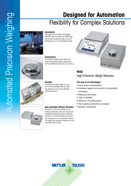
WXSHigh-Precision Weigh ModulesThe sum of all advantages • Avoid cross-contaminationwith an additional pre-load of up to 78 g.A u t o m a t e d P r e c i s i o n W e i g h i n g2A u t o m a t e d P r e c i s i o n W e i g h i n gModel Specific Weighing DataType informationWXS205WXS205DU WXS204Nominal capacity (nominal load)200 g 200 g 200 g Maximum capacity220 g 220 g 220 g Maximum capacity, fine range -111 g -Maximum preload M1)78 g 78 g 78 g Readability0.01 mg0.1 mg 0.1 mg Readability, fine range -0.01 mg-Internal adjustment333Limit Values M2)Repeatability (σ) (nominal load) ≤ M3) 0.04 mg 0.07 mg 0.1 mg Linearity deviation ≤0.15 mg 0.2 mg 0.25 mgRepeatability, fine range (σ) ≤ M3)-0.03 mg (100 g)-Eccentric load deviation (test load) ≤0.3 mg (100 g)0.3 mg (100 g)0.4 mg (100 g)Sensitivity temperature drift ≤ M4)0.3 mg/°C 0.3 mg/°C 0.3 mg/°CTypical Values M5)Repeatability (σ) (nominal load) ≤0.031 mg0.064 mg 0.08 mgRepeatability, fine range (σ) ≤-0.03 mg -Settling time ≤3 s2 s 2 sAmbient ConditionsCompensated temperature range M6)10 °C to 30 °C Operating temperature range 5 °C to 40 °C Storage temperature range -20 °C to 70 °C Relative air humidity range M6)20% to 80%Warm-up time after power-on M6)60 minutesMaximum preload on top of “preload reference” weighing pan to maintain maximum capacity. Applicable for stationary conditions within compensated temperature and relative air humidity range. σ = standard deviation (99.7 % of weighing results within ± 3 σ). Weighing tests according to OIML R76 A.5.3 at stationary condi-tions. Applicable for stable environmental conditions and optimal filter settings. Condition to meet the specified limit values.General DataElectrical connection Power supplyInput: 100–240 V AC, 50/60 Hz, 0.5 A; Output: 12 V DC, 2 ACommunication interface RS232Ethernet (optional)Maximum weight update rate92 values/s and 23 values/s G1)IP protectionModule during weighing IP30Module during cleaning G2)IP45Electronic unitIP40MaterialsWeighing pan/platform Stainless steel (1.4404 / 316L); plasticWeigh module housing Stainless steel (1.4404 / 316L)Electronic unit housingStainless steel (1.4404 / 316L)In combination with a terminal. With plastic cover mounted.Scope of DeliveryItem Description Item NumberWXSLoad cellWeighing panØ = 50 mm, without threaded holes, approx. 68.5 g Adapter weighing pan (preload reference)Ø = 36 mm, with threaded holes, approx. 10 g Electronic unit Including mounting bracket and DIN clipCable WX 90/1.5Connection cable weigh module to electronic unit (90°/1.5 m) 111 214 40Power supplyIncluding country specific power cableProduction certificate Declaration of conformity Quick guide Terminal SWT S1)Monochrome touch screen display (including 0.575 m and 2.0 m terminal cables, protective cover)111 210 57Cable terminal S1)2 m111 321 33Only with WXSS versions.3Typical ConfigurationTerminal PWTTerminal SWT incl. cable WXS Cable WX Electronic unitAccessories from METTLER TOLEDOScope of deliveryTerminal SWT incl. cable (included in WXSS orders)For more informationMETTLER TOLEDO Group Industrial DivisionLocal contact: /contactsSubject to technical changes© 01/2019 METTLER TOLEDO. All rights reserved Document No. 30313184 A MarCom Industrial/ind-WXSOrder InformationWXS Model 205205DU204Standard SI Units *Standard SI Units *Standard SI Units *No terminalWXS205S/15111 210 03WXS205SV/15111 213 03WXS205SDU/15111 210 08WXS205SDUV/15111 213 08WXS204S/15111 210 23WXS204SV/15111 213 23Monochrome terminal SWTWXSS205111 210 01WXSS205V 111 213 01WXSS205DU 111 210 06WXSS205DUV 111 213 06WXSS204111 210 21WXSS204V 111 213 21“EU” legal-for-trade version.With SWT terminal.WXSS205/M 111 212 61WXSS205DU/M 111 212 66WXSS204/M 111 212 81* Only SI units are displayed: g, mg, ctAccessoriesItemDescriptionItem number PictureCable WX 90/0.5Connection cable weigh module to electronic unit (90°/0.5 m)111 214 42Cable WX 90/5Connection cable weigh module to electronic unit (90°/5 m)111 214 41Terminal PWT Color touch screen display, multi-user functionalities 111 210 58Cable terminal 0.575 m 111 321 24Cable terminal0.945 m111 321 29Interface second RS232CAdditional RS232C interface in electronic unit111 32500Interface Ethernet Additional Ethernet interface in electronic unit 111 325 15Weighing below adapter Adapter for below weighing applications 111 21081Draft shield Glass draft shield with sliding door 111 21071。
卓先2.5P说明书

热泵热水器功能说明书名称热泵热水器编号设计卓先电子器材实业有限公司审核批准版本A0 共 10 页卓先电子器材实业有限公司自动制冷热水制热空调通风除霜除湿设定温度室内温度定时开定时关AMPM时间故障参数补水换气123456891011127℃℃-+设置开关/定时时间循环定时1234567891011显示:1、 工作模式显示;2、 开机时显示设定温度,查询时显示查询代码;3、 定时开关机显示;4、 设置时显示设置代号和参数,调定时时显示定时时间,其它时间显示时钟;5、 电辅热工作符号显示;6、 水泵工作符号显示;7、 压缩机工作符号显示;8、 正常工作时显示水温,查询时显示查询温度; 9、 换气符号显示; 10、 补水符号显示; 11、电源指示灯。
一.概述1.本控制器适用于热泵热水系统,并配有线控液晶按键操作面板,采用RS485通讯,增强抗干扰能力,加长通讯距离,减少了连接线,方便了用户的安装,正常温度使用及显示范围是—15℃—80℃,电源为220V/110V/50Hz;2.这不仅简化了操作、安装工程,同时也降低了成本。
最主要的是系统运行更科学、更合理、更可靠。
3.基本功能:1)工作模式:独立热水模式+电加热;2)可显示回水温度及设置温度,具有查询功能;3)掉电自动记忆各种参数(可选);4)具有完善的保护功能及显示;5)具有定时开关机能(实时开关);6)操作面板的温度设定范围是25℃~60℃;7)温度控制精度:1℃;8)一台压缩机控制运行;9)感温器故障自检功能;10)直观大屏幕液晶显示设计.4.电控板的控制信号1)压缩机×1:单压机系统(220V/20A);2)外风机×1:单风机(220V/7A);3)水泵×1(220V/7A);4)电加热×1(220V/20A);5)曲轴加热×1(220V/7A);6)四通阀×1(220V/7A);7)补水阀×1(220V/7A);8)旁通阀×1(220V/7A);(备用)9)温度感温控头×4(水温、外盘管、外环境、压缩机出气温度);10)操作面板通信(线控);11)保护开关×5(高/低压保护开关【常闭】、水流开关【常闭】、高/低水位开关【常闭】);二.功能说明1.上电后,液晶屏显示北京时间,2.“强制制冷水”功能,按住[开关]键10秒后进行转换,制冷→热水→制冷…。
二标车2x35使用说明书

25G/T 2×35kVA+15kVA型逆变电源使用说明书HS2.938.521SS南京华士电子科技有限公司Nanjing Huashi Electronic Scientific Co., Ltd目录一、系统简介 (3)二、主要技术参数 (3)2.1 逆变器主要技术参数 (3)2.2 逆变器控制电路技术条件 (3)2.3 冷却方式 (3)2.4 效率 (3)2.5噪音 (3)2.6防护等级 (3)三、工作原理及流程 (4)3.1 开机自检 (4)3.2工作的必要条件 (4)3.3启动工作 (4)3.4 过分相 (4)3.5逆变器故障 (4)3.6故障转换 (4)3.7关机和重新启动 (4)3.8 2×35kV A逆变器控制程序流程图 (5)四、故障处理及注意事项 (8)4.1故障定位 (8)4.2故障类别及处理方法 (8)4.3注意事项 (8)五、25G/T 2x35kV A+15kV A型逆变电源主回路元件清单 (9)六、25G/T 2x35kV A+15kV A型逆变电源外部端子特性图 (10)七、25G/T 2x35kV A+15kV A型逆变电源主回路原理图 (10)八、25G/T 2x35kV A+15kV A型逆变电源主回路元器件布置图......10. 附表一. (11)附图一 (12)附图二 (13)附图三 (15)九、整机维护与保养 (16)(一)、维护和保养前注意事项: (20)(二)、维护和保养内容: (20)(三)、维护完毕注意事项: (21)一.系统简介25G/T 2x35kVA+15kVA型逆变电源是把母线DC600V逆变成两路独立输出的三相AC380V以及隔离输出的单相AC220V,该电源主要为空调客车和相应供电制式的客车或动车组的空调设备及其它设备提供交流电源(为空调,电加热器以及其他车载AC380V及AC220V用电设备供电)。
本说明书主要阐述了该逆变电源的基本参数、构成、原理以及使用、维修注意事项等。
E205U USB CONDENSER MICROPHONE 使用手册说明书

E 205UUSB CONDENSER MICROPHONE简体中文详见P .15www .superlux .com .tw保固服务Made in chinaSuperlux 舒伯乐针对在符合使用手册上所载明之使用方法,给予自购买日期起一年的所有材质及制造质量的保证期限。
此保证期限将依据在不同国家或地区而有所调整。
请联络当地的经销商以或得更多的信息。
在有效期限内,若发现任何材质或生产质量,或是任何功能无法正常使用,Superlux 将进行维修或更换零件。
此保证条款只针对经由Superlux 所授权的代理商或经销商所卖出的产品,然而以下的状况将不在保证条款内:由于意外、错误的使用、不正当的使用、自行修改或维修,运送过程中造成的损害,不遵守说明书上所载明之使用方法、未经由Superlux 所授权的公司执行维修的动作,由非授权的经销商所提出的要求,或任何Superlux 产品其上的序号贴纸巳经无法辨识或巳经修改或被移除者。
Superlux 产品的维修只能由原厂所授权的维修中心或是授权的代理商或经销商为之。
未经授权的维修、保养或修改将无法获取相关的保证,并且排除在保证条款之外。
在保证条款下的维修保证,必须在提出当地授权代理商或经销商的销货收据下,才能获得保障。
而且必须在提出采买日期才能决定你的Superlux 产品是否在保证期限内。
要获得原厂授权的维修保固,请联络业经授权的代理商、经销商或经由电邮***********************.tw 与我们联络。
本产品符合 FCC 法规B 类型第15章的规范。
在满足以下两个条件才允许操作本产品:(1)本产品不会产生干扰,并且(2)本产品必须能够接受接收到的包括可能导致装置意外操作的任何干扰。
适合使用的场所为家庭或办公室。
国际行销和业务中国地区行销和业务********************.tw ***********************.tw******************************.tw ********************.tw+886-2-26931323System Requirements USBUSB 1.1 or 2.0, poweredRAM64MB RAM (minimum )Operating SystemMicrosoft Windows 2000 Professional EditionMicrosoft Windows XP Home/Professional Edition (service pack 1.0 or later, or use the USB audio driver update from Microsoft)Microsoft Windows Vista™ Business Edition Apple Computer Mac OS X 10.0 or later EditionApple Computer Mac OS X 10.1 or later Edition P/N: LB10E205U0102 2012 DecSAFETY PRECAUTIONSWARNINGCAUTION3Safety symbols-“WARNING” AND “CAUTION”- and messages described below are used in this manual to prevent bodily injury and property damage which could result from mishandling. Before operating your product, read this manual first and understand the safety symbols and messages so you are thoroughly aware of the potential safety hazards.WARNING: Indicates a potentially hazardous situation which, if mishandled, could result in death or serious personal injury.CAUTION: Indicates a potentially hazardous situation which, if mishandled, could result in moderate or minor personal injury, and/or property damage.Do not expose the unit to rain or an environment where it may be splashed by water or otherliquids, as doing so may result in fire or electric shock.Do not attempt to modify this product. Doing so could result in personal injury and/or productfailure. Do not subject to extreme force and do not pull on the cable or failures may result. Keep the device dry and avoid exposure to extreme temperatures and humidity.2GENERAL DESCRIPTIONFEATURESSmooth, flat frequency response Plug in and start recording, no drivers required Up to 16 bit / 48 kHz sampling Powered by USB power, no external power required Headphone output and volume control Includes pivoting stand mount, threaded adapter, and USB cable The E205U is a high quality condenser microphone with an advanced A/D and USB interface which gives you digital recording capabilities instantly with no external digital interface or software driver required. It is USB compatible with Mac, Windows, and most DAW software programs, including GarageBand. The E205U offers premium quality audio recording with ease and mobility, and with its pivoting stand mount and 9.8 ft. (3-meter) USB cable, the E205U is a valuable kit for any project studio.LAYOUTout connector: 1/8-inch (3.5mm)studio monitors.USB indicator : When it is lit up , it means the USB connection is done and E 205U get the power from USB interface .USB connector : E 205U involves a USB B -type connector , and it is allowed to connect to any device with USB interface .54Unit: mm/inchThrough optional table stand HM 6, You may put the E 205U on a table and do recording .ON A STANDBy using a microphone stand , the E 205U can be mounted on it for recording .CONNECTIONSA separated 3-meter cable with USB A -type connector allowed to be connected to a computer with USB port . Note : Make sure to use a powered USB prot .ON A TABLEUSB ConnectorMOUNTING cØ38 (Ø1.5”)QUICK START1. You can position the E 205U on an optional stand by using included accessories .2. Be sure to position the side of grille net to the sound source and keep the Superlux logo and LED indicator face thedirection of sound source.3. Plug the B type connector of the included USB cable into the USB socket on the bottom of the E 205U .4. Now , plug the other end of the USB cable into an available powered USB port on your computer .Note : Be sure to check the USB audio device driver setup for Windows and Mac OS to confirm your computer has recognized the E 205U .5. Next , launch your DAW , turn down the main output level and select the E 205U for the input .6. Set up a mono record track in your DAW .7. Now , setup the level of the E 205U and there are few ways to do this depending on your computer system . You can setthe microphone 's input level in the Sound playback in Windows or in the Sound dialog box in the System Preferences if you are using the MAC OS .8. Set level of the microphone by raising the Input level control in your DAW or system to about half way up .9. Next, put on your headphones that is connected to the headphone output of E205U, position the E205U to the soundsource then adjust the volume control until you reach a comfortable listening level.Now , follow the instructions of your DAW software to enable the track for recording and you 're ready to record .Note : if the microphone level of E 205U are too loud or not enough , please check your DAW software or refer to Troubleshooting page in this manual to adjust the level in Windows and Mac computer system :76USB AUDIO DEVICE DRIVERWindows Operating SystemsIf you encounter problems, make sure the driver was properly installed.From the Control Panel , open Sounds and Audio Devices .In the Audio tab , look for Superlux E205U in the drop -down menus for Sound playback and Sound recording.superlux E205UMACINTOSH OSX OPERATING SYSTEMSOpen the Sound Preference window from System Preferences . Select Superlux E205U from both the Input and Output tabs .98Superlux E205USuperlux E205UUSBNote : Garage Band users :open Garage Band before plugging in the microphone to automatically select the USB device .2. Now click the checkbox in the column in Setup .Thru Audio /MIDI Superlux E205USuperlux E205UUsing the Direct Monitor1.To turn direct monitoring on or off , open the Setup utility located in the folder inside the Applications folder .Audio /MIDI Utility 1110TROUBLESHOOTINGSPECIFICATIONSNote: specifications are subject to change.ACCESSORIES FURNISHEDOPTIONAL ITEMSHM 56 spider shockmount1312HM85 pivotingstand mount。
富士S205使用技巧(打印版)

富士S205使用技巧大全1、点测光怎么用?点测光是从P档开始的手动档才有的测光方式,从AUTO开始的自动档没有。
首先转到这些档,按相机最中间的那个功能键,出现调节菜单,然后用上下键调到测光处,再用左右键调到中间只有一个点的测光方式,按功能键(func)确定,然后半按快门键对准需要测光的部位到绿框内,快门保持半按,再按一下左上角那个+/-键,使得曝光锁定,然后松开快门,重新构图,最后就是按动快门。
2、什么是光圈优先与快门优先?分别在什么情况下用?我们知道,佳能A系列有光圈优先与快门优先档,他们分别用在什么情况下呢?光圈越大,则单位时间内通过的光线越多,反之则越少。
光圈的一般表示方法为字母“F+数值”,例如F5.6、F4等等。
这里需要注意的是数值越小,表示光圈越大,比如F4就要比F5.6的光圈大,并且两个相邻的光圈值之间相差两倍,也就是说F4比F5.6所通过的光线要大两倍。
相对来说快门的定义就很简单了,也就是允许光通过光圈的时间,表示的方式就是数值,例如1/30秒、1/60秒等,同样两个相邻快门之间也相差两倍。
光圈和快门的组合就形成了曝光量,在曝光量一定的情况下,这个组合不是惟一的。
例如当前测出正常的曝光组合为F5.6、1/30秒,如果将光圈增大一级也就是F4,那么此时的快门值将变为1/60,这样的组合同样也能达到正常的曝光量。
不同的组合虽然可以达到相同的曝光量,但是所拍摄出来的图片效果不同。
3、“景深”的概念。
所谓景深就是指当镜头对焦于被摄体时,被摄体及其前后的景物有一段清晰的范围,这个范围叫景深。
a、光圈优先大多用在拍人像以及风景时光圈优先就是手动定义光圈的大小,相机会根据这个光圈值确定快门速度。
由于光圈的大小直接影响着景深,因此在平常的拍摄中此模式使用最为广泛。
在拍摄人像时,我们一般采用大光圈长焦距而达到虚化背景获取较浅景深的作用,这样可以突出主体。
同时较大的光圈,也能得到较快的快门值,从而提高手持拍摄的稳定。
SaltDogg LS5 双105加喷墨液喷雾系统安装与操作手册说明书
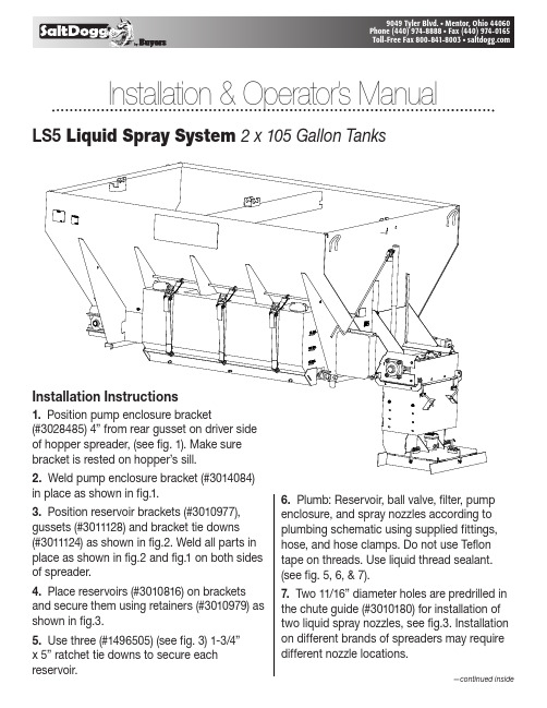
I n stal l a ti o n & Operator’s Manual LS5 Liquid Spray System 2 x 10⁵ Gallon TanksInstallation Instructions1. Position pump enclosure bracket(#3028485) 4” from rear gusset on driver sideof hopper spreader, (see fig. 1). Make surebracket is rested on hopper’s sill.2. Weld pump enclosure bracket (#3014084)in place as shown in fig.1.3. Position reservoir brackets (#3010977), gussets (#3011128) and bracket tie downs (#3011124) as shown in fig.2. Weld all parts in place as shown in fig.2 and fig.1 on both sides of spreader.4. Place reservoirs (#3010816) on brackets and secure them using retainers (#3010979) as shown in fig.3.5. Use three (#1496505) (see fig. 3) 1-3/4”x 5” ratchet tie downs to secure each reservoir.6. Plumb: Reservoir, ball valve, filter, pump enclosure, and spray nozzles according to plumbing schematic using supplied fittings, hose, and hose clamps. Do not use Teflon tape on threads. Use liquid thread sealant. (see fig. 5, 6, & 7).7. Two 11/16” diameter holes are predrilled in the chute guide (#3010180) for installation of two liquid spray nozzles, see fig.3. Installation on different brands of spreaders may require different nozzle locations.Fig. 219.026.06.7526.01.75WELD ALL AROUND BRACKETS AND GUSSETSBRACKET, TIE DOWNSWELD ALL AROUND BRACKET, TIE DOWN4" FROM GUSSETWELD BOTH SIDESWELD ALL AROUND301112830109773028485Fig. 13010816301097914965053010180Fig. 3Cab Controller Installation Instructions (Fig. 5)1. Install cab controller (#WSE1) in cab for convenient driver operation. Mounting bracket and fasteners included.2. Route 8' wire harness (#WSE24) under dash from controller (#WSE1) to truck’s fuse panel.3. Ground “black” wire from controller to truck frame or truck’s battery (not dash).4. Attach “green” wire in 8' wire harness (#WSE24) to a fused and keyed 15 Amp hot wire circuit.5. Connect main power “white” wire in 8' wire har-ness (#WSE24) to fuse box that is “hot” full time or to battery “positive”.6. Route the 25' wire harness (#WSE25) from the rear of the spreader to the cab. Plug connector on controller (#WSE1) to the connector on pump harness (#WSE25).Fig. 5 WSE1 Cab Controller front viewFig. 5 WSE1 Cab Controller back viewWSE2525' Cable ConnectorWSE248' Cable ConnectorFig. 4LS5 can be adapted for Buyers' 4 and 4.5 cubic yard spreaders.25' Harness#WSE25Fig. 6 Plumbing Dia.WSE6168WSE6065WSE33WSE33WSE333000269WSE34WSE13WSE7WSE9WSE9WSE9WSE15WSE143000269WSE7WSE15WSE14 WSE2from3010816WSE2WSE30WSE6168WSE11WSE9WSE10toWSE22Fig. 7 Nozzle AssemblyFig. 8 Filter/Valve AssemblyLiquid Spray System Routine Maintenance RESERVOIR:-Inspect fittings for leaks from cracks or looseness-Inspect filler/breather for cracks. Depressbreather to check for adequate spring pressure or binding PLUMBING:-Inspect hoses/fittings/ball valve for leaks, cracks, looseness, chafing, binding etc.FILTER :-Remove and clean filter element every 8 to 10 hours or as needed depending on how clean de-icing liquid isPUMP-PRESSURE SWITCH & ENCLOSURE:-Inspect wiring for wear and loose or corroded connections-Inspect door and gasket to prevent corrosion NOZZLES:-Inspect operation for even spray pattern. Remove and clean as needed CAB CONTROLLER:-Inspect lights, switch, and flow control knob -Inspect wire harness and connections for wear and loose or corroded connections CLEANING:-Wash with hot water and soap after each use STORAGE:-Store inside to prevent freezing-Drain liquid de-icer from tank/s and hoses when not in use for more than two days or during extremely low temperatures-RV anti-freeze or windshield washer fluid should be run through the system for several minutes to flush de-icer from the system to preventcomponent freezing especially for end of season storageLiquid Spray System Operating Instructions 1. Read all instructions before operating. Always wear hand, eye, and skin protection when working with de-icing chemicals. Make sureeveryone is standing clear of liquid spray system before operating.2. Inspect all plumbing for leaks.3. Open ball valve (#WSE10) at the reservoir.4. Make sure reservoir has adequate supply of clean de-icing liquid. Do not operate pump without liquid.5. Before turning the cab controller on, turn the black speed control knob counter clockwise until it stops to set the pump at the slowest speed.6. To energize system, turn red power button to illuminate LCD screen “on” position.7. Increase pump speed to desired liquid spray application rate by turning black knob clockwise.8. If the red low pressure warning light/alarm comes on, the reservoir is empty or the pump is off. Do not operate pump without liquid. Note: Low pressure light and alarm will sound each time system is started. This is normal and occurs until sufficient pressure is achieved to open pressure switch (turning off light/buzzer).9. Close ball valve (#WSE10) at the reservoir when not in use.Liquid Spray System Trouble Shooting GuideMotor & Pump Operate Erratically: 1,2,3,4,5 (Possible Problem)Motor runs – Pump does not: 1,2,3,4,5,6,7 (Possible Problem)Motor & Pump fail to operate: 8,9,10,11,12 (Possible Problem)POSSIBLE PROBLEM: REPAIR:1. Little or no de-icer in tank/s Fill 2. Clogged filter Clean 3. Clogged Nozzles Clean 4. Damaged suction hose Replace 5. Ruptured pump diaphragm Replace 6. Ball valve is closed at tank/s Open valve 7. Frozen parts Thaw out 8. Bad electrical connection Inspect 9. Motor failure- burned/seized Replace 10. Cab controller on-off switch not turned on Turn on 11. Bad cab controller on-off switch Replace 12. Blown fuse in cab controller or fuse panelInspect/replaceCAUTIONAlways wear hand, eye, and skin protection when working withde-icing chemicals. Use extreme care!CAUTIONAlways wear hand, eye, and skin protection when working with de-icing chemicals. Use extreme care!Bill of MaterialsLS102 1 Enclosure Assy., Wetting System, Electric WSE3 1 Pump, Agriculture Electric Diaphragm WSE4 1 Switch, Pressure N. C. WSE6065 1 Hose, 1/2" ID, 6½" WSE9 10 Clamp, HoseWSE21 3 Connector, Insulated Electrical Spring WSE22 1 EnclosureWSE18 1 Connector, Cord, 1/2", Nonmetallic WSE27 1 Nut, Barbed Wing, 1/2" – 8 Washer, Flat 1/4" SAE ZN – 4 Nut, Elastic Stop 1/4"-20 Zinc – 4 Screw, Hex HD Cap, 1/4-20 x 1¼WSE25 1 Harness, Wire with Connector 25' Power WSE20 1 Bushing, Reducer 1/2" x 1/4" WSE23 1 Barb Hose, 1/2" MPT x 1/2" HB WSE19 1 Tee, 1/2F x 1/2F x 1/2F NPT WSE29 1 Nut, ConduitWSE2 4 Nipple, Hex 3/4 x 1/2 Poly WSE7 2 Nozzle Body, BrassWSE34 2 Tee, Female Branch 1/4 x 1/4 x 1/4 WSE10 2 Valve, Ball Polypropylene WSE11 2 FilterPART NO.QTY.DESCRIPTIONWSE13 1 Elbow, Brass 1/4 NPTF x 1/4NPTF WSE14 2 Nozzle Cap WSE15 2 Rubber Nozzle– 4 Washer, Flat 1/2 x 1-3/8" OD Stainless WSE24 1 Harness, Wire with Connector 8' Power WSE30 2 Barb Hose 3/4 NPT x 1/2 HB WSE6168 1 Hose, Poly 1/2 ID x 168"3009727 1 Instructions, LS1, LS2 Electric Wetting 3010979 2 Retainer, Weldment3011044 4 Lid 5", Tank Wetting System 3028485 1 Bracket, Pump Enclosure LS4 3011124 2 Bracket, Tie Downs LS4 3011128 6 Gusset, LS4– 6 Washer, Split Lock - 1/2", SST –6 Nut-Hex, 1/2"-13 Nut, SS149650501 6 Spreader Hold Down Strap (one only) WSE1 1 Controller, Wet Spray SystemWSE33 6 Barb Hose 1/4" NPT x 1/2" I.D. Hose 3010977 6 Bracket Reservoir3010816 2 Reservoir 105 Gal. Poly 3011428 1 Instruction LS5PART NO.QTY. DESCRIPTIONRESERVOIR & COMPONENTS MAY CONTAIN HAZARDOUS MATERIAL.HANDLE WITH CARE.EQUIPMENT INSTALLERS & OPERATORS:TURN OFF ALL POWER BEFORE PERFOMING ANY SERVICE OPERATIONS.• Follow Recommended Operating Procedure.• Keep Equipment In Safe Operating Condition At All Times.• Recognize & Avoid Hazards While Operating,。
联想 IdeaPad S205 说明书

i第1章 认识您的电脑 (1)正视图 (1)左视图 (3)右视图 (4)底视图 (5)第2章 学习基本操作 (7)初次使用 (7)使用交流电源适配器和电池 (9)使用触控板 (11)使用键盘 (12)使用外接设备 (14)特殊键和按钮 (16)系统状态指示灯 (17)保护您的电脑 (18)第 3 章 使用因特网 (19)有线连接 (19)无线连接 (21)第 4 章 一键拯救系统 (26)一键拯救系统 (26)附录A 产品特殊声明 (27)“能源之星”型号信息 (27)商标 (29)索引 (30)目录1第1章 认识您的电脑- - - - - - - - - - - - - - - - - - - -注释:本手册中的插图可能与实际产品不同。
请以实物为准。
注意:•请勿将显示屏打开超过130度。
关闭显示屏时,请注意不要在显示屏和键盘之间遗留下钢笔或任何其它物件。
否则,显示屏可能会损坏。
2第1章 认识您的电脑内置摄像头使用此摄像头进行视频交流。
内置麦克风内置麦克风,有效滤除背景噪音,可用于视频会议、配音或简单的录音。
无线模块天线(仅限特定型号)内置天线确保了无线通讯的最优接收能力。
电脑显示屏带LED 背光的液晶显示屏提供了清晰明亮的图形显示。
系统状态指示灯有关详细信息,请参见第17页的“系统状态指示灯”。
电源按钮按此按钮打开电脑。
一键拯救系统按钮电脑处于关机状态时,按此按钮可打开一键拯救系统(如果安装了一键拯救系统)。
注释:有关详细信息,请参见第26页的“第 4 章 一键拯救系统”。
触控板触控板起传统鼠标的作用。
注释:有关详细信息,请参见第11页的“使用触控板”。
a b c d e f gh第1章 认识您的电脑3左视图 - - - - - - - - - - - - - - - - - - - - - - - - - - - - - - - - - - - - - - - - - - - - - - - - - - - - - - - - - - - - - - - - - - - - - - - - - - - - - - - - - - - - - - - - - - - - - - - - - - - - - - - - - - - -交流电源适配器插孔此处连接交流电源适配器。
S205B按键开关荷重曲线仪说明书

一、概要:本机台适用于各类按键、开关的『荷重-行程』曲线测试,透过计算机的分析,可精确测量待测物荷重及行程的相对应变化曲线,可准确控制测试荷重、行程、测试速度、试验次数及暂停时间等,并且可以依据同一测试物设定群组以方便比较。
试验时,所有曲线图形都自动产生,可免除旧式荷重曲线机必须移动纸笔的烦琐动作,尤其是对于较难测试之圆弧按键,更有专用之重测按钮来解决,直至试验图形满意才储存,对于操作者提高工作效率,的确有很大的帮助。
加上本机台使用伺服马达及Windows窗口控制系统,操作简单方便,且所有资料皆可储存,绝对是一部值得信赖的高性能测试仪器。
二、机台规格:最大承载测试重量 -------- 10Kgf最大测试行程 ------------ 100mm最小显示行程------------ 0.01mm、0.001mm(Option)测试速度范围 ------------ 0 ~ 100mm/min机台尺寸 ---------------- 300mm X 270mm X 500mm机台净重 ---------------- 31kgf机台电源 ----------------AC220V控制系统尺寸 ------------ 450mm X 560mm X 200mm控制系统净重 ------------ 20Kgf荷重元 ------------------ 2Kgf(精度0.2%FS)荷重元最小读值 ---------- 0.01gf荷重元治具 -------------- Φ径2、4、6、8、10mm工业计算机一组(含屏幕、打印机)三、机台各部名称说明:3-1、测试机台:(A)荷重元固定座:此固定座是用来固定荷重元之用,固定时请注意荷重元之左右水平及前后水平,以避免因荷重元有一倾斜角度而影响试验的准确度。
(B)荷重元:在测试时,用以检出测试力量的装置。
可依据试验择适合的治具Φ径固定于感测端上以方便量测。
AGA 型 1列型电气控制箱 说明书
702( 06/06/30)防水型( I P65)·压铸铝制 ø30控制元器件标配型电气控制箱。
可选择 1〜 5点标配各种规格(触点结构、电压、颜色、标记牌等)控制元器件的标准型电气控制箱。
• 也可根据用途,从品种丰富的 ø30系列的控制元器件中自由选择组装元器件,组合成各种多应用范围的控制箱。
• 除标准箱以外,还备有本体内深厚度深型。
最适合安装照明按钮开关等面板后伸出长较深的元器件。
(详细内容请查阅 705页。
)❏规格•共通最小使用负载(参考值)= 3V AC/DC · 5mA (可使用范围取决于使用条件和负载种类。
)•元器件安装孔ø30.5孔(防转加工)。
安装孔的间距为 50mm 。
•防水衬套合成塑料制,将螺丝放在衬套中,将箱子固定在墙壁上。
•接线引入装置(壁挂型)带压铸铝制引入接口的箱体。
1 〜 3点用 .........带 HNA22 G3/4(公称 22)4〜 5点用 ................带 HNA33 G1(公称 28)也可选择带电缆引入用 HNAG 型接地接口箱体。
•立杆型(直立型)立杆为普通结构用碳钢钢管( S TK ),基座为铸铁制。
喷涂漆的颜色与本体相同( 5Y7/1半抛光)。
组装元器件元器件安装孔本体接线引入装置防水垫圈不锈钢螺丝基座立杆AGA型1列型电气控制箱703 (06/06/30)AGA型1列型电气控制箱704(06/06/30)AGA型1列型电气控制箱705(06/06/30)AGA 型 1列型电气控制箱706(06/06/30) 13270重量∶约 5.6kgAGA型1列型电气控制箱707 (06/06/30)。
富士S205EXR旗舰技术说明
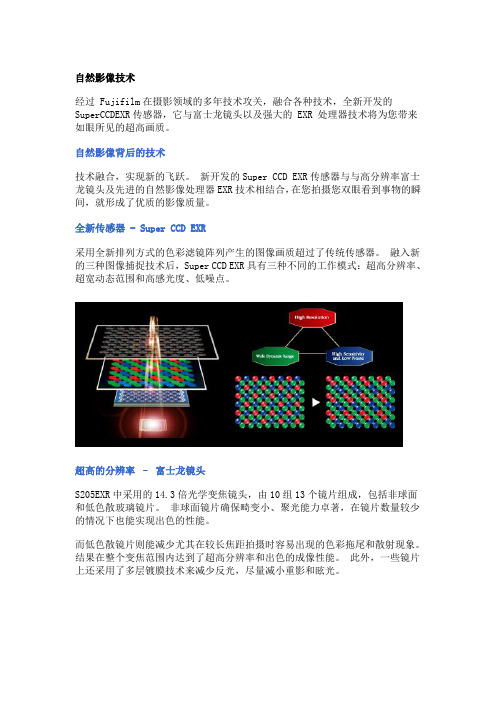
自然影像技术经过 Fujifilm在摄影领域的多年技术攻关,融合各种技术,全新开发的SuperCCDEXR传感器,它与富士龙镜头以及强大的 EXR 处理器技术将为您带来如眼所见的超高画质。
自然影像背后的技术技术融合,实现新的飞跃。
新开发的Super CCD EXR传感器与与高分辨率富士龙镜头及先进的自然影像处理器EXR技术相结合,在您拍摄您双眼看到事物的瞬间,就形成了优质的影像质量。
全新传感器 - Super CCD EXR采用全新排列方式的色彩滤镜阵列产生的图像画质超过了传统传感器。
融入新的三种图像捕捉技术后,Super CCD EXR具有三种不同的工作模式:超高分辨率、超宽动态范围和高感光度、低噪点。
超高的分辨率–富士龙镜头S205EXR中采用的14.3倍光学变焦镜头,由10组13个镜片组成,包括非球面和低色散玻璃镜片。
非球面镜片确保畸变小、聚光能力卓著,在镜片数量较少的情况下也能实现出色的性能。
而低色散镜片则能减少尤其在较长焦距拍摄时容易出现的色彩拖尾和散射现象。
结果在整个变焦范围内达到了超高分辨率和出色的成像性能。
此外,一些镜片上还采用了多层镀膜技术来减少反光,尽量减小重影和眩光。
获得超高EXR画质的图像处理技术为了获得逼真的画质,S205EXR处理器采用先进的电荷技术控制 Super CCD EXR 传感器的电荷输出。
这种方法在确保色彩更自然、分辨率更高、处理更快的同时,减少了各种形式的噪点。
该技术还使快速连拍成为可能,促成了新的多帧技术,使S205EXR 能自动将一次快门下的多张照片合并处理成特殊效果的图像。
Super CCD EXR 传感器更接近于人眼所见的成像效果,超乎您的想象。
备受赞誉的可切换式 EXR 传感器可实现理想拍摄效果,确保摄影的高分辨率、高对比度与弱光下的漂亮效果。
三种图像捕捉技术Super CCD EXR 具有超高照片质量,实现了“3合1”传感器组合:“精细捕捉技术”(高分辨率)、“像素联合技术”(高感光度、低噪点)以及“双重捕捉技术”(超宽动态范围)。
快克205焊台使用说明书
Lead Free Soldering Station 大型智能无铅电焊台高周波发热极速回温操作手册感谢您购买我们的无铅电焊台,本产品是专为无铅焊接而设计的,使用前请仔细阅读本说明书,阅读后请妥为保管,以便日后查阅。
目录注意事项……………………………………………………………………… 部件名称……………………………………………………………………… 装置和使用电焊台…………………………………………………………… 参数…………………………………………………………………………… 休眠……………………………………………………………………………选择合适的烙铁头来适应焊接要求………………………………………… 校准烙铁温度………………………………………………………………… 烙铁头的使用………………………………………………………………… 烙铁头的保养………………………………………………………………… 错误标记……………………………………………………………………… 排除故障指南………………………………………………………………… 如何检查发热器及传感器元件……………………………………………… 更换保险丝…………………………………………………………………… 规格…………………………………………………………………………… 烙铁头…………………………………………………………………………注意事项△!警告本使用说明书之“警告”和“注意”的定义如下:△!警告:滥用可能导致使用者死亡或重伤△!注意:滥用可能导致使用者受伤或对涉及物体造成实质破坏。
△!注意当电源接通时,烙铁头温度处于高温状态。
鉴于滥用可能导致灼伤或火患,请严格遵守以下事项:● 请避免本焊台的滥用,应按照操作说明使用本品。
● 切勿触及烙铁头附近的金属部份。
● 切勿在易燃物体附近使用烙铁头。
● 通知工场其他人士,烙铁头极易灼伤,可能引起危险事故。
休息时或完工后应关掉电源。