AR-510操作手册
Antari DarkFX Spot 510 IP用户手册说明书
For surface mounting
For truss mounting
6
Service and Maintenance
Important! Smoke fluid residue, dust and any excessive particle residue will degrade product performance, cause overheating and damage fixture. Damages
4
DarkFX Spot 510 IP is wired to output terminal of DarkFX Drive 4. Each output terminal can connect one DarkFX Spot 510 IP fixture.
Physical Installation Important
weight of fixture. ․ Make sure fixture installed in a well ventilated area. ․ Consider lamp replacement and routine maintenance access when selecting installation
caused by inadequate cleaning or maintenance are not covered by product warranty.
Cleaning ․ Unplug fixture from DarkFX Drive 4 before starting. ․ Use vacuum or air compressor and soft brush to remove dust on components
ABBACS510用户使用说明

低压交流传动用户手册ACS510-01 变频器(1.1...160 kW)2 ACS510 用户手册ACS510 变频器手册Industrial IT 标记及Drive IT产品名称为ABB公司所持有的注册商标。
CANopen 为CAN 组织所持有的注册商标。
ControlNet 为ControlNet 国际组织所持有的注册商标。
DeviceNet 为Open DeviceNet 供应商协会所持有的注册商标。
DRIVECOM 为DRIVECOM 用户组织所持有的注册商标。
Interbus 为Interbus Club 组织所持有的注册商标。
LonWorks 为Echelon 公司所持有的注册商标。
Metasys 为Johnson Controls 公司所持有的注册商标。
Modbus 和Modbus Plus 为施耐德公司所持有的注册商标。
Profibus 为Profibus 贸易组织所持有的注册商标。
Profibus-DP 为西门子公司所持有的注册商标。
通用手册ACS510-01 用户手册(1.1…160 kW)• 安全指南• 安装• 启动• 内置现场总线• 现场总线适配器• 诊断• 维护• 技术数据可选件手册( 现场总线适配器、I/O 扩展模块等。
手册和可选件一起发货)继电器输出扩展模块• 安装• 启动• 诊断• 技术数据© 2009 ABB 版权所有ACS510 用户手册3安全指南安全指南警告! 只允许专业技术人员安装ACS510!警告! 即使电机已经停止, 功率端子U1, V1, W1和U2, V2, W2 以及UDC+, UDC-或BRK+ , BRK- 上面依然存在危险电压!警告! 主回路电源得电后即存在危险电压。
电源断开后等候5 分钟(让中间回路电容充分放电)再打开前面板。
警告! ACS510 断电后,在继电器端子上( RO1…RO3 ) 依然可能有外部危险电压。
警告! 当两个或两个以上的变频器的控制端子并联使用时,用于控制连接的辅助电源应来自同一个单元或外部电源。
ABB变频器ACS510说明书

ABB变频器ACS510说明书ABB变频器ACS510说明书低压交流传动用户手册ACS510-01 变频器 (1.1...110 kW)ACS510 用户手册ACS510 变频器手册通用手册ACS510-01 用户手册(1.1…110 kW).安全指南.安装.启动.内置现场总线.现场总线适配器.诊断.维护.技术数据可选件手册( 现场总线适配器, I/O 扩展模块等,手册和可选件一起发货 )继电器输出扩展模块.安装.启动.诊断.技术数据IndustrialIT标记及DriveIT产品名称为ABB公司所持有的注册商标。
CANopen 为 CAN 组织所持有的注册商标。
ControlNet 为 ControlNet国际组织所持有的注册商标。
DeviceNet 为 Open DeviceNet 供应商协会所持有的注册商标。
DRIVECOM 为 DRIVECOM 用户组织所持有的注册商标。
Interbus 为 Interbus Club组织所持有的注册商标。
LonWorks 为 Echelon公司所持有的注册商标。
Metasys 为 Johnson Controls公司所持有的注册商标。
Modbus 和 Modbus Plus 为施奈德公司所持有的注册商标。
Profibus为 Profibus 贸易组织所持有的注册商标。
Profibus-DP 为西门子公司所持有的注册商标。
. 2004 ABB 版权所有ACS510 用户手册安全指南警告! 只允许专业技术人员安装 ACS510!警告! 即使电机已经停止,功率端子 U1, V1, W1和 U2, V2, W2 以及 UDC+, UDC-或BRK+ , BRK- 上面依然存在危险电压 !警告 !主回路电源得电后即存在危险电压。
电源断开后等候 5分钟(让中间回路电容充分放电)再打开前面板。
警告! ACS510断电后,在继电器端子上( RO1…RO3)依然可能有外部危险电压。
华为AR系列路由器01-01 AMI配置(AR502EG-L)(开始)

1.2.2 数据采集
电表采集
设备可以通过实时抄表、定时抄表、补抄三种方式采集电表的数据。可采集的电表数 据包括实时数据、历史数据和事件数据。其中,历史数据包括负荷曲线数据、小时数 据冻结数据、日冻结数据、月冻结数据。
息),供EDM异常分析使用,以判别表箱是正常工作中被打开还是异常打开。
1.2.3 数据存储
设备数据存储的主要作用就是把通过数据采集获取的电表数据存储到设备中,储存的 数据主要包括冻结数据和事件数据。
l 存储机制 数据记录采用循环存储机制。数据存储满后,会把最早的数据覆盖。
l 存储容量设计 最大支持电表数1024个。 数据存储中存储的数据包括事件数据和冻结数据两类: – 事件数据 事件数据分为一般和重要两类事件,来源分为终端事件和电表事件等。 一般事件,是指对客户影响不大的事件。重要事件,是指对客户影响较大的 异常事件。用户可自行配置事件的等级以区分一般事件和重要事件。
抄读任务并抄读电表存储的冻结数据。定时抄表由设ቤተ መጻሕፍቲ ባይዱ内部定时器触发。
– Step2:电表返回结果给设备。 如表1-1所示,定时任务采集的数据种类具体分为以下几种:
文档版本 01 (2018-05-18)
版权所有 © 华为技术有限公司
5
Huawei AR500&AR510&AR531&AR550&AR1500&AR2500 系 列工业路由交换一体机 配置指南-AMI(命令行)
l 补抄
补抄是针对所有定时抄表任务在执行过程中未成功抄读的数据量进行补充性抄 读。
当采集通道空闲时,允许设备对电表进行空闲补抄。设备可以轮循对每一个电表 当日需要采集但未采集成功的数据量进行补抄,这些数据量包括曲线数据冻结、 小时数据冻结、日数据冻结、月数据冻结及电表事件采集任务中未采集成功的数 据量。
AR-510操作手册

绪 言承蒙惠顾,购得AR-510打印机。
在使用本机前,请细阅这本用户手册,以便能正确使用。
并且请妥善保存这本手册,万一有不了解或故障时,这本手册会带给您很大的帮助。
AR-510打印机是得实集团与日本西铁城公司合作开发、生产的超高速24针平推式票据打印机。
AR-510采用高速打印头设计,打印速度高达188汉字/秒,打印针寿命3亿次,前后两种平推式进纸,1000万字符长寿命耐用大色带,GB18030中文大字符集硬字库及多款防改写数字、半角英数字及八款条形码打印,使AR-510在硬件方面别具特色。
在软件方面,AR-510秉承了得实系列打印机的高性能、高兼容性,可兼容所有STAR、EPSON和OKI 打印机,方便的自动撕纸功能及参数设置功能是得实打印机的特色。
打印机针调整和断针自动补偿功能是得实打印机的专利技术。
AR-510设计精美、外形精巧、功能齐全、用途广泛,是税务、银行、运输、医院、商业、POS系统等票据用户的极佳选择。
目录第1章安装打印机.....................................1-11.1开箱和检查......................................1-11.2放置打印机......................................1-21.3打印机部件......................................1-31.4安装和更换色带盒................................1-51.5打印机和主机连接................................1-81.6连接电源........................................1-91.7安装打印驱动程序...............................1-10第2章纸的安装和使用.................................2-12.1选纸............................................2-12.2调校打印头间隙..................................2-12.3装入单页纸......................................2-22.4装入链式纸......................................2-4第3章控制面板.......................................3-13.1按钮及其指示灯..................................3-13.2开机功能........................................3-43.3组合功能........................................3-7第4章参数设置.......................................4-14.1如何选择打印机参数设置..........................4-14.2如何进行参数设置................................4-24.3如何进行双向测试及纵向校正.....................4-184.4如何进行打印针自动调整设置.....................4-224.5如何进行打印针补偿设置.........................4-244.6票据通设置和使用...............................4-264.7如何进行用户调整设置...........................4-294.8如何恢复出厂参数设置...........................4-32第5章故障和保养.....................................5-15.1故障处理........................................5-15.2保养与维护......................................5-6第6章规格...........................................6-16.1打印机规格......................................6-16.2接口接头引脚....................................6-46.3字符集..........................................6-86.4控制码摘要表...................................6-146.4.1ESC/P和LQ仿真控制码摘要表..................6-146.4.2OKI仿真控制码摘要表........................6-18安全规范企业公开信息:1.售后服务请致电全国各地得实服务网点电话,或拨打:400-810-9998(手机)800-810-9998(免费)2.产品工作、待机、休眠及关闭状态的最大及最小能耗如下:产品使用状态最大能耗最小能耗工作时78W 10W待机8W 7W休眠7W 7W关闭小于0.1W 0注:只有当产品无任何外接输入电源时,才能实现零能耗。
ABB 510 说明书

低压交流传动用户手册ACS510-01 变频器 (1.1...132 kW)2ACS510 用户手册ACS510 变频器手册Industrial IT 标记及Drive IT 产品名称为ABB 公司所持有的注册商标。
CANopen 为 CAN 组织所持有的注册商标。
ControlNet 为 ControlNet 国际组织所持有的注册商标。
DeviceNet 为 Open DeviceNet 供应商协会所持有的注册商标。
DRIVECOM 为 DRIVECOM 用户组织所持有的注册商标。
Interbus 为 Interbus Club 组织所持有的注册商标。
LonWorks 为 Echelon 公司所持有的注册商标。
Metasys 为 Johnson Controls 公司所持有的注册商标。
Modbus 和 Modbus Plus 为施耐德公司所持有的注册商标。
Profibus 为 Profibus 贸易组织所持有的注册商标。
Profibus-DP 为 西门子公司所持有的注册商标。
通用手册ACS510-01 用户手册 (1.1…132 kW)•安全指南•安装•启动•内置现场总线•现场总线适配器•诊断•维护•技术数据可选件手册( 现场总线适配器, I/O 扩展模块等,手册和可选件一起发货 )继电器输出扩展模块•安装•启动•诊断•技术数据© 2007 ABB 版权所有ACS510 用户手册3安全指南警告! 只允许专业技术人员安装 ACS510!警告! 即使电机已经停止, 功率端子 U1, V1, W1和 U2, V2, W2 以及UDC+, UDC-或BRK+ , BRK- 上面依然存在危险电压!警告!主回路电源得电后即存在危险电压。
电源断开后等候5分钟(让中间回路电容充分放电)再打开前面板。
警告!ACS510断电后,在继电器端子上 ( RO1…RO3 )依然可能有外部危险电压。
警告! 当两个或两个以上的变频器的控制端子并联使用时,用于控制连接的辅助电源应来自同一个单元或外部电源。
Plantronics VOYAGER 510-USB 蓝牙耳机系统 说明书

用户指南Plantronics VoY aGEr™ 510-UsB目录包装内的物品包装内的物品3耳机(正面与侧面视图) PerSono Suite 软件 CD部件充电横向麦克风杆调整呼叫控制按钮充电连接采用 WindSmart®技术的去除噪音麦克风交流电源充电USB 充电状态指示灯配对开启/关闭耳机将耳机与蓝牙手机配对启或关闭耳机。
耳机开启之后,指示灯将闪烁蓝灯。
电池电量变低时,指示灯将闪烁红灯。
配对注:耳机与 USB 蓝牙适配器在出厂时已相互配对。
但是如果您是单独购买的 USB 蓝牙适配器,或者希望将另一部耳机用于现有的适配器,则必须对它们进行配对。
安装 PerSono SUite 软件Plantronics PerSono Suite 软件在您的蓝牙耳机与电脑上的兼容网络电话应用程序之间提供了链接。
PerSono Suite 软件使您可以通过耳机通话控制按钮,远程检测并应答/结束来自网络电话应用程序的呼叫。
此外,PerSono Suite 还提供了一些基本配置以及关于系统的状态信息。
有关详情,请参阅第 12 页。
在 /SoftphoneCompatibility 上查看 PerSono Suite 兼容性列表,了解关于网络电话兼容性的最新信息。
如果 PerSono Suite 目前不支持您的网络电话,请参阅第 12 页。
1. 插入 CD 之后,进入 PerSono Suite 主屏幕,然后单击“安装 PerSono Suite 软件”。
2. 您的网络电话可能需要您选择希望使用哪种音频设备。
有关详情,请参阅网络电话的文档。
:未检测到耳机:检测到耳机,但是没有与:检测到耳机,与:检测到耳机,与配置和状态要拨打电话,只需通过软电话应用程序拨打号码。
要应答或结束通话,请按下通话控制按钮。
在使用 PerSono Suite 时,耳机与 USB 蓝牙适配器之间的收音机链接只有在通话期间才会激活。
RNS510的使用秘籍

几个RNS510的秘籍几个RNS510的秘籍秘籍一,关闭系统:按住魔语键 + 左/右箭头RNS510的设计是无论你怎么按电源钮还是干脆拔钥匙,都无法真正得关闭系统。
所以当RNS510的系统一旦出现故障,必须强制关闭系统后再重启才能解决。
秘籍二,进工程模式:关闭系统(用“秘籍一”的方法)» 按住SETUP键 + 电源钮开机查看系统信息和参数,升级地图都会用到工程模式。
秘籍三,行驶中显示视频画面:开始播放视频» 当汽车保持在静止状态时按魔语键» 听到提示音» 按TONE键» 车辆恢复行驶状态,视频画面继续显示RNS510自带了DVD播放功能,但它非常“人性化”的一个设计是当车辆在行驶时视屏画面会被强制关闭,但音频信号会继续输出,只有当汽车保持静止状态时时视频画面才会恢复显示。
但是当我们副驾驶座上坐着的老婆孩子一定要看画面怎么办呢?这个秘籍就是解决这个问题的。
科普一下“魔语”按钮:知道的同学请直接无视,抛砖引玉期待其他秘籍补充…RNS510 怎样往硬盘里拷贝数据?送图片谢谢大家sd卡或者光盘内,机器可支持文件,在“选择”菜单中将需要拷入的文件后面的菜单按钮点开,选择“复制”即可!RNS510 系统与导航升级作业!高六的RNS510 系统与导航升级其实非常简单,特别是升级导航地图,简直是傻瓜操作!其实升级系统也是比较简单的。
升级系统的官方方法:打开导航同时按下如图2的3个按钮同时松手屏幕会黑屏此时放入系统升级的光盘需要按2次OK 升级开始大概30多分钟之后升级系统完成!系统升级过程我用魅族M8拍了部分图片!(清晰度一般,请谅解)1、3、4、6、然后再升级地图直接放入地图的光盘系统提示是否装入硬盘点“是”则开始安装如想看进度可按一下出仓键(比较简单就不上图了)大概20分钟完成地图容量1.5G左右信息点增加很多如升级完地图为白屏不要惊慌你可以开车出去逛逛我那天装完地图白屏(因为车库里封闭好搜星定不了位)开车才开出10多米 GPS开始搜星定位地图重新出现超级详实的地图定位精准!而且不会再出现地图白屏啦哈哈哈!关于mfd3高尔夫6原装rns510导航版本升级的指导写给diy原装导航DVD和需要自行安装的车主高尔夫6顶配版的原装dvd导航时RNS510(也称作MFD3),以下知识只提供给安装好并且已经解码了用户。
深圳市锐尔威视科技有限公司 REVB-A50 产品使用手册说明书

A50方案板产品使用手册深圳市锐尔威视科技有限公司2019.9.5 Ver.A目录目录硬件资源描述 (4)核心硬件资源 (4)接口资源 (4)显示驱动能力 (5)视频编解码能力 (5)底板接口资源 (5)软件资源描述 (6)提供JA VA层API源码 (6)底板硬件设计说明 (6)接口说明 (7)接口定义描述 (8)扩展模块连接说明 (11)MIPI屏 (11)LVDS屏 (12)RGB屏 (12)MIPI摄像头 (13)4G通讯模块 (13)更新固件方法 (14)USB更新 (14)TF卡更新 (16)固件修改工具使用说明 (18)安装D RAGON F ACE (18)修改开机信息 (19)第一张开机L OGO (19)第二张开机L OGO (20)开机动画和开机音乐 (20)修改系统配置 (20)修改系统属性BUILD.PROP (21)修改INIT.RC (21)修改LCD配置 (22)修改触摸配置 (22)修改屏幕旋转方向 (22)修改自启动应用 (22)串口使用说明 (23)GPIO说明 (24)硬件资源描述核心硬件资源CPU:全志A50四核主频1.5GHzGPU:Mali-400MP2PMU:AXP2231DRAM:1GB LPDDR3FLASH:8GB eMMCWIFI+BT:XR829集成Audio Codec接口资源1路USB OTG 2.0,可做HOST1路USB HOST 2.0 高速ECHI协议480Mbps1路SDIO,可接SD卡1组RGB/LVDS复用的显示屏接口1组MIPI-DSI显示屏接口1组MIPI-CSI摄像头接口1路音频Headphone2路音频Microphone1路LRADC,可做按键检测1路SPI接口1路I2S接口,用于接声卡芯片2路IIC接口,用于接CTP、G-Sensor等3路UART接口5个GPIO口复位信号输入开关机按键,支持休眠唤醒提供5组外设电源,给LCD、CTP、Camera等外设供电支持外部DC、锂电池、USB三种供电方式,自动检测支持由DC-5V和USB给电池充电PCBA尺寸:59mm*46mm引脚数量:132显示驱动能力RGB:18bit 1920*1080 5/7寸转接双8LVDSLVDS:单8 1366*760 7~15寸MIPI:4-lane 1920*1200 5~10寸视频编解码能力编码能力:1080P@60fps H.264/MJPEG解码能力:1080P@60fps H.264/MJPEG多种格式解码:Mpeg1/2, Mpeg4 SP/ASP GMC, H.263, H.264 BP/MP/HP, VP8, WMV9/VC-1等底板接口资源4个USB2.0口,2个A母座,其中一个可用于Device,2个4P-2.0插座3组TTL串口(其中1组可复用为一个SPI)1个TF卡座,支持最大64G容量TF卡1个耳机插座1个麦克风接口1个MIPI-CSI摄像头接口1个百兆以太网RJ45接口1个RGB屏接口,带电容触摸接口1个LVDS屏接口,带电容触摸接口1个MIPI屏接口,带电容触摸接口1组SPI接口(可复用为串口)1组IIC接口1组按键接口:POWER RESET LRADC5个GPIO全网通4G模块MiniPCI-E插座标准SIM卡座RTC电池座CR1220锂电池接口,支持3.7~4.2V电池DC5.5电源座,12V电源输入4P-2.54插座,12V电源输入4P-2.54插座,5V和3.3V电源输出(WIFI+BT集成在核心板上)PCBA尺寸:135mm*85mm软件资源描述搭载Android8.1系统(内核版本:Linux-4.9),系统经过锐尔威视科技深度优化定制,启动快,运行流畅不死机,已ROOT,可做带Google GMS认证的系统;支持WIFI、蓝牙、以太网、4G网络;支持RGB、LVDS、MIPI接口的屏幕;用户可由PC端的固件修改工具定制个性化固件,如修改开机图片、开机动画、开机声音、安装/卸载应用、自启动应用、更改LCD屏配置、设置屏幕旋转方向、修改机器信息等,不开放系统源码,仅提供固件,用户可直接开发APP,节省开发周期,可为项目用户定制系统。
InSPIre-510a 操作手册
3D InSPIre Solder Paste Inspection Systems三维在线焊膏检测设备Operation Manual操作手册(Sinic-Tek InSPIre-510a Series)Sinic-Tek Vision Technology Co., Ltd.思泰克光电科技有限公司Email: info@Web-Site:Page 1Copyright by Sinic-Tek Vision Technology Co., Ltd.在使用设备之前请详细阅读本说明书,并且充分理解说明书的内容后再操作。
未接受过有关本设备培训的人员禁止操作此设备。
目录一.安全注意事项........... .. (3)二.机器开关及指示灯 (6)三.机器开机操作..... .. (7)四.程序的制作 (8)4.1如何导入Gerber文件并转换 (8)4.2如何编辑检测Job程序 (8)4.3如何使用检测Job程序进行检测 (9)五.机器关机操作... . (10)六.软件主界面的介绍 (11)6.1 用户主界面 (11)6.2Gerber转换软件 (12)6.3 编程软件Peditor (14)6.4 过程控制软件SPC (21)七.本产品使用时的承诺事项 (26)Page 2Copyright by Sinic-Tek Vision Technology Co., Ltd.三.机器开机操作1.打开机器电源开关(按顺时针方向90度旋转),白色电源指示灯变亮。
2.打开电脑电源开关,在Windows桌面打开e-SPIre软件。
3.按下机器的运行开关,绿色运行指示灯变亮。
4.点击主界面上的Home ,机器将自动做初始化处理。
(如气压不正常,SMEMA信号错误,安全门未锁好等原因,机器将停止初始化) Page 7Copyright by Sinic-Tek Vision Technology Co., Ltd.四.程序的制作4.1 如何导入Gerber文件并转换成*.mdb文件4.1.1 在主界面上点击菜单下的PEdit 。
【视光精品】验光流程(尼德克基础)

• 电脑验光仪 • 综合验光仪
ARK-510A 简易操作手册
STEP1. 准备 1 开启操作者右边的电源
2 下颌接触下颌托,额头轻松地接触前额托
(上下调节下颌托,使受检者的眼角与刻度相平)
STEP2. 设定
眼角刻度
1 选择测量模式(验光/角膜曲率)
电源开关
CS:角膜尺寸,PS:瞳孔尺寸 PD:瞳孔距离
问诊
三、配镜用途 了解顾客对视力的要求
问诊
四、戴镜史 了解顾客的消费水平,戴镜的时间长短。为了将来处方的 决定。
问诊
五、旧镜使用情况:旧眼镜的视力,舒适程度。
以关心和关爱的态度进行,面对受测者要适时的加入用眼知识.
验光的三步法---是什么?
•(1) 前面是什么 •(2) 是用来做什么 •(3) 请您(如何配合)
上下运动按钮
STEP3. 操作 1 操作控制杆,将被测眼调至画面中心 2 指导受检者凝视设备中的固视灯 3 调焦
(请根据画面内各种操作记号进行调节)
4 开始测定 5 取得必需的测定次数之后,将设备拉离受检者 6 将设备移至另一只眼,开始测定
STEP4. 打印 1 按打印键打印测定结果
STEP5. 关机 1 关闭操作者右侧的电源
他觉式验光——电脑验光
话术: 现在在您面前
的是一台电脑验光仪。 是用来粗略测量你的度 数的,请您坐好,睁开 双眼放松向前看。
一、电脑操作要领:(他觉式 )
• 1、客坐椅移至正确位置.高低合适 • 2、消毒:请问你对酒精过敏吗? • 2、受测者挺胸并将双脚置于踏板上. • 3、下颌与前额自然贴紧,两眼自然平视. • 4、眼位调整,并提示受测者转动现象(控制眨眼).
验光的主要流程
帕顿510系列模块化浪涌保护器使用说明书
600 W for 1 mS
Response Time (RS-422): Clamped to + or - 6 volts after 0.5 µS,
200 Amps with a 8/20 µS pulse
Response Time (RS-232): Clamped to + or - 25 volts after 0.5 µS,
1.2 SERVICE
All warranty and non-warranty repairs must be returned freight prepaid and insured to Patton Electronics. All returns must have a Return Materials Authorization number on the outside of the shipping container. This number may be obtained from Patton Electronics Technical Service at (301) 975-1007. Packages received without an RMA number will not be accepted.
Plantronics Voyager 510 USB Bluetooth 头戴式耳机用户指南说明书

Plantronics VoYaGEr ™ 510-UsBBLUETOOTH ® HEADSET SySTEmUSER GUIDEPACKAGE CONTENTSHeadset (front and side view) PerSonoCall® software CD WELCOMEThis User Guide provides instructions on the setup and usage of the Plantronics Voyager 510 USB Bluetooth headset system. Before getting started, please review the safety booklet included in your package. For additional help, service or support information, refer to the product warranty card or visit .FEATURES CHARGINGHorizontal boom adjustmentCall control buttonCharge connectionNoise-cancelling microphone with WindSmart® technology USB chargingStatus indicator lightPAIRINGPowering headsetPairing headset with Bluetooth phoneon or off.The indicator light flashes blue when the headset is on. The indicator light will flash red when PAIRINGPairing headsetNOTE: The headset and USB Bluetooth adapter are paired to each other at the factory. However, if you have purchased a USB Bluetooth adapter separately, or if you wish to use a replacement headset with your existing adapter, the units must be paired.INSTALLING PERSONOCALL ® SOFTWAREPlantronics PerSonoCall ® software provides the link between your Bluetooth headset and compatible softphone applications on your computer. PerSonoCall software provides the ability to remotely detect and answer/end a call from your softphone application via the headset call control button.In addition, PerSonoCall provides some basic configuration and status information about the system. See page 10 for more details.Check the PerSonoCall compatibility list at /personocall for the most current information on softphone compatibility. If your softphone is not currently supported by PerSonoCall, please refer to page 14.1. With the CD inserted, go to the PerSonoCall main screen and click on “Install the PerSonoCall Software”.: No headset detected : Headset detected, no radio link to USB Bluetooth adapter : Headset detected and radio link to USB Bluetooth adapter active : Headset detected and radio link to USB Bluetooth adapter is locked onCurrent Status screen INSTALLING PERSONOCALL SOFTWARERight-click on the headset system tray icon and choose “Options”. This will bring up the PerSonoCall Basic Options and Current Status screens.Basic Options screenReplacing the ear tipRotate the microphone horizontally and vertically as illustrated, to select for left or right ear wearing. The illustration shows conversion from right to left ear wearing. Reverse the procedure to convert from left to right ear wearing.Slide the headset over and behind your ear. Press gently towards your ear for a snug fit. Adjust the microphone position so that it is directed towards your mouth.Inserting a new ear tipADJUSTING FITWearing the headsetTo make a call , press the call control button to take the softphone off the hook. You should hear a dial tone.To answer or end a call , press the call control button.When using PerSonoCall, the radio link between the headset and the USB Bluetooth adapter will only be active during a call. This is the default setting intended to preserve the battery life of the headset. However, you may wish to have the radio link active when not on a call so you can listen to other audio sources, such as streaming audio on your PC. You can lock the radio link on in two ways:• Basic Options screen—check the box for "Lock headset radio link on"—see page 10.• Right click on system tray icon—and choose "Lock radio link on".NOTE: Locking the radio link on for extended periods of time will significantly reduce the USING YOUR HEADSETAdditional featuresOnly with mobile phoneAnswering/ending/making calls with PerSonoCall on softphoneRedialling last numberTo activate last number redial, double-click the call control button. You will Switching a call from phone to headset To switch an active call from your phone to your headset, briefly press the call The Voyager 510-USB headset has multipoint technology which allows you to switch seamlessly between two audio devices. You can answer a call from either your PC-based softphone or your mobile phone by pressing the call control button. The headset must be paired to both devices and then to enable this functionality, see "Allow call control button to toggle the headset’s radio link" on the Basic Options screen on page 10.Multipoint versatilityINDICATOR LIGHTSBluetooth device Connected to headset Flashes blue USING YOUR HEADSETTo adjust the listen or speak volume of the softphone, please refer to the softphone user documentation.TROUBLESHOOTING FOR VOYAGER 510-USB• Lower the listen volume on your softphone until the distortion disappears.• If the distortion is still present, lower the listen volume control on the computer.• Adjust volume on headset. See page 16.• Speak volume is too high. Lower the speak volume on your softphone until the noise disappears. If the noise is still present, lower the microphone volume control on the computer.Sound in headset is distorted. I can hear echo in headset.I can hear too much background conversation or noise.• Check compatibility list on / personocall to ensure your softphone is compatible for remote answer and disconnect.• Headset battery needs to be charged. See page 5.• Headset is not paired to the USB Bluetooth adapter. See page 8.• When a PC goes into standby or hibernation, the USB Bluetooth adapter is no longer powered on. Ensure your PC is in an active state.• Ensure PerSonoCall software is installed My Voyager headset does not work with the softphone I am using on my PC (I cannot answer or disconnect from the headset call button).ProblemSolutionProblemSolutionTECHNICAL ASSISTANCEVisit our web site at /support for technical support including frequently asked questions, compatibility and accessibility information. The Plantronics Technical Assistance Center (TAC) is also ready to assist you on 0800 410 014.Plantronics Ltd Wootton Bassett, UK Tel: 0800 410 014Plantronics B.V. Hoofddorp, Nederland Tel: 0800 752 6876 (NL) 00800 752 687 66 (BE/LUX)Plantronics Sarl Noisy-le-Grand, France Plantronics Acoustics Italia Srl Milano, Italia Numero Verde: 800 950 934Plantronics Iberia, S.L. Madrid, España Tel: 902 415 191 +34 91 640 47 44 (ES) Tel: 800 844 517 (PT)。
510系列NVR监控录像机指南说明书

510 Series NVR Surveillance Recorder Web Interface Quick StartGuide2For maximum control and convenience, your system should be connected to the Internet via a local network router. For installation, you must be able to access this network through a personal computer.Internet connectivity allows you to use OvrC, a powerful remote maintenance service. See for details.If your surveillance system is isolated from the Internet, go to SnapAV .com and download the technical reference manual for this product, which has a chapter that steps you through installation without using the web interface.Required Equipment }The NVR and all cameras to be installed }Network connection for the NVR}Admin rights to a network computer that can access the surveillance system }Phillips screwdriver}T wo AAA batteries for the remote controlYou can acquire a PDF of the full NVR technical reference manual, hard drive installation guide, and other materials from SnapAV .com: visit the product page and click on the support tab.If you are going to install extra hard drives in the recorder, do so now before beginning installation.WARNING: This product can expose you to chemicals including cadmium, which is known to the State of California to cause cancer, and phthalates, which are known to the State of California to cause birth defects or other reproductive harm. For more information go to .Safety Tips (4)Set Up the Hardware (5)Install and Run the Luma Utility (6)Edit the Network Settings (7)Optional: Prep for Plugin-Free Browsers (8)Complete Port Forwarding. . . . . . . . . . . . . . . . 9 Start the Web Interface .................10Luma Link (10)Check the Cameras (11)Set Up Dynamic DNS (12)Camera Passwords (13)Create Users and Set Passwords (14)Calibrate the System Time (15)You’re Done! (16)What’s in the BoxAside from this guide, your package includes:}The Luma NVR}Extra screws for mounting an additional internal hard drive into your NVR }SATA cables for connecting an additional internal hard drive in your NVR }Rack ears for installing your NVR into a rack}Screws for attaching the rack ears to the NVR}USB mouse}Remote control}Power cord}Stick-on rubber feet for the unit if you will not be installing it in a rack4510 Series NVR Quick Start Guide}Handle this device with care}Do not strike or shake this device.}Do not operate this device beyond its specifiedpower source ratings.}Protect the power cord from being stepped on orpinched, particularly where it connects to thedevice and to the power outlet.}Do not drop items through the ventilation slots.f something falls inside the device, turn offthe power immediately and contact qualifiedpersonnel for service.}Do not expose this device to water or moisture.Moisture may damage the device and causeelectric shock.}T ake immediate action if the device becomeswet: turn the power off and contact qualifiedpersonnel for service.}Do not use this device in humidity above 85%.}Do not use this device near any heat sourcessuch as radiators, heat registers, stoves, or othersuch heat-generating equipment.}If mounting in a closed space, include adequateventilation. Do not block ventilation openings.}The performance and lifespan of the hard driveis affected by temperature. Use this device intemperatures ranging from 14–131 °F.}Handle the hard drive with care.}You can damage the hard drive if this deviceis moved while the hard drive is still spinning.I f you must move the device, even just toreposition it, follow the shutdown procedure inthe technical reference manual (available online)and wait at least 30 seconds before moving it.}If servicing or exchanging the hard drive, protectit from static electricity. Use a grounded staticwrist guard and mat to properly ground yourselfand the hard drive.}Do not use an electric screwdriver to remove orinstall a hard drive.}Clean this device with a dry cloth. Do not usestrong or abrasive detergents when cleaning thedevice chassis. I f dirt is hard to remove, use amild detergent and wipe gently.}Make a note of the system settings and savethem. This helps when changing the systemconfiguration or with recovery if unexpectedfailure or trouble occurs.5510 Series NVR Quick Start GuideCaution: Do not power up the NVR until these steps are complete.1. If desired, install the NVR in the rack. If not, attach the rubber feet to the bottom corners of the unit.2. Connect the mouse to the USB port on the rear panel. We suggest that you leave the front USB unused andaccessible for later use.3. If desired, connect a local monitor to the VGA or HDMI port.4. Connect your IP surveillance cameras to the camera ports. T o connect your cameras through your local network, consult the technical reference manual (available online) for additional setup.5. Connect your network cable to the Ethernet port.6. Connect the power cord and turn on the power switch.Camera(s)Optional AC Power6510 Series NVR Quick Start GuideUse the Luma Utility to locate your surveillance hardware and set up communications. This is a PC-only utility.Visit your product page at and download the Luma Utility installer from the Supporttab. Y ou must use v3.0.0.54 build 20180202 or later! Earlier versions of the utility will not work!Run the installer. You can click through and accept the defaults.Connect your PC to the network and run the Luma Utility. It searches the local network for all LumaSurveillance devices. If your NVR does not appear, ensure that the network connections are secureand that the unit is powered up, then click the Refresh button.Click on the entry for your NVR to view its details. If the NVR is inactive, use the text boxes at the lower right of the Luma utility window to activate the NVR by creating a new secure password.}Passwords cannot be longer than 16 characters. T o ensure compatibility with the local interface, passwords can only contain numbers, letters, spaces, and the following special characters: . , : - / }Use a password that is long and easy to remember. A password like parisinthespring is much more secure and easier to remember than a password like D3x^7b.7510 Series NVR Quick Start GuideT o change the network settings at a later date, consult the NVR manual.Suggested Best PracticesEnsure the Enable DHCP box is activated. In your router, reserve an IP address and assign it to the NVR’s MAC address (found on the recorder’s box, or under System Settings > System Information ). See your router’s documentation for details.Change the Server and HTTP PortsThe HTTP port defaults to 80. This port enables you to access your recorder through a web browser.The server port defaults to 8000. This port enables the Luma mobile application to access your system.For security reasons, we suggest you change your ports and record the new numbers on the back page of this guide. Consult your server or router manual for common and reserved port numbers to avoid.T o confirm changes, enter the password that you just created and then click Save.8510 Series NVR Quick Start GuideWith the update to firmware v3.4.95 build 191127, Chrome, Safari, and Microsoft Edge can view your system remotely. Port forwarding setup allows you to access the NVR from the internet for remote viewing and other operations. These settings are entered in your network router, typically in a menu called Port Forwarding or Applications and Gaming. Refer to your router manual for help.T o remotely access your recorder from a browser other than Internet Explorer, forward port 7681 on your router. This port allows you to use browsers that no longer allow plugins (Chrome, Firefox, etc.).As you cannot perform port translation, both your internal and external port must be 7681. You do not need to append this port at the end of your URL as it does not replace your HTTP port. It is simply a special port that needs to be forwarded on your router and that is the sole place the port is used. Thus, if your HTTP port is (forexample) 8042, your web address stays the same: e.g., :8042 .Find the NVR settings you need, then log in to the router and enter the new port forwarding rules.9510 Series NVR Quick Start GuideOnce you’ve finished, your device’s URL (e.g., ) gets you to the login page of your NVR, no matter where you are. If you changed your HTTP port from the default location (80), add a colon and thenew port number to the URL (e.g., :8042).Port Forward Attached CamerasIf your cameras are attached directly to your NVR and you want to access individual cameras remotely, you’ll also need to set up port forwarding for them.The cameras are accessed with the IP address of the NVR, modified by port numbers 65001 (for camera 1) through 65016 (for camera 16). Forward these ports on your router. This can also be referenced through the camera management links shown on page 11.10510 Series NVR Quick Start GuideGet the Luma Plug-InOpen your browser, type the IP address of the recorder (from page 7) into the address bar, and hit Return.Below the login window, there may be a link that reads, “Please click here to download and install the plug-in. Close the browser when installing the plug-in.” If so, download the plug-in and close all instances of your browser, including any running in the background.Install the LumaWebComponents plug-in.Restart your browser and return to your recorder’s login window.Enter admin for the user name, and the password you just created on page 6.You might get a pop-up message that asks you whether you want to run the Luma WebComponents plug-in. You must allow the plug-in to access your system.Be sure to save your recorder’s page as a favorite in your browser.LumaLinkLumaLink is our free remote access service that makes it easier than ever to set up your customer’s Luma app for remote viewing.Using point-to-point (P2P) technology to replace traditional DDNS/port forwarding, LumaLink provides you witha robust setup solution that’s efficient and convenient, while offering increased security to clients.T o use LumaLink simply add the device to your OvrC account, log in to LumaLink on your Luma mobileapplication, and refresh your device list.After log-in, your screen shows the live page, which should look similar to the illustration below. If a camera is out, check its connection to your NVR, and ensure that it is powered up.Edit Camera Settings (Optional)T o adjust camera settings, click on thesettings icon ( ). In the configurationscreen, click on Camera Management.This displays a table of all I P camerasconfigured for the NVR. In the rightmostcolumn is a link to each such IP camera.This link opens a new tab in yourbrowser for your camera’s web interfacemenu (see your camera manual fordetails). It can only be used from withinthe network.T o modify a camera, clicking on its entry to highlight the row. Click the Modify button to edit the camera. Luma cameras use the LUMA protocol; third-party cameras may require the ONVIF protocol.Reinstalling Network CamerasIf you are taking cameras that were previously attached to anetwork and plugging them directly into your NVR, you mustdo a hardware reset on the cameras. See your camera’s manualor the technical reference manual for details.This allows you to connect to yoursurveillance system from anywhere, via theInternet, using a web address that’s easy toremember.Click on Basic Network Settings > DDNS.Click the box labeled Enable DDNS,then choose a type from the DDNS Typemenu. Next, choose a server address. Werecommend WirepathDDNS. This serviceis hosted specifically for use with Lumaequipment and requires no additional setupafter following these steps.Enter your desired domain in the Domainbox. This creates a personalized serveraddress, which is shown under Device URL.If someone has already registered your desired domain, the system adds a unique ID (typically two to four digits) to your domain. If you do not like these digits, try another domain or server address.Example: If you choose the domain myhome, your system’s URL is . If someone has already claimed the myhome URL, then your system’s URL would be something like . Click Save to finalize the settings here.Note: When your ports have also been forwarded properly on your router, the Status entry changes to indicate that the DDNS status is normal (as shown in the illustration).When the Luma NVR is activated, it sets the password for all the connected camerasto match the NVR password that you created on page 6.f you add a camera manually, you must enter the camera’s password. Default passwords represent a security risk after installation. We strongly recommend that you change the password on any camera that has a default password like admin.T o add a camera manually, click on Camera Management > IP Camera.At the top of the window, click on the Modify button. This opens a dialog box that lets you enter the camera information, including:}IP address}protocol}the camera’s management port} a custom name (e.g. Front Porch)}the camera’s username and password}set Adding Method to Manual.Camera passwords cannot be longer than 31 characters. The camera password can only contain numbers and letters; no spaces or special characters.For added security, use a password that is long and easy to remember.Click on User Management.Click the Add button. Enter the new account’s user name and password. Account names can be up to 32 characters long, and can contain numbers and letters only. We recommend that you add accounts by individual users’ names, so that if someone reboots the system or erases a log, you know which user did it.Choose the account’s level. There are two levels for users: operator and user. The only difference is the default permissions they are given. You can customize permissions for each account individually. See the technical reference manual (available online) for more details.Important! T o protect your security and privacy, your device must be activated with a valid password for you to be able to view them when using LumaLink.Click on System Settings and select the Time Settings tab.Synchronize the TimeChoose your time zone. North American time zones range from GMT-10:00 (Hawaii) to GMT-03:30 (Newfoundland).By default, the system uses network time protocol (NTP) to synchronize your system to Coordinated Universal Time. We strongly recommend using NTP to keep your system well calibrated.If you want to use manual time sync, or if your system is isolated from the Internet, see the technical reference manual (available online).Disable DST if NecessaryIf you are in a location that does not observe daylight saving time, click the Enable DST checkbox to deselect it.Click Save to confirm changes.Your system is now operational. Next, you’ll want to customize your system for your customer’s needs. Using the simple web interface, you can:}Set protocols for remote computers for when they log in to the surveillance system.}Change the cameras’ frame rates to manage hard disk space.}Set a custom recording schedule.… and more!T o learn more, go to the product page at and download the technical reference manual.If you need further clarification, please email support@. For more information, instructional videos, support documentation, or ideas, visit our website and view your item’s product page at .3-Year Limited WarrantyThis Luma Surveillance™ product has a 3-Y ear Limited Warranty. This warranty includes parts and labor repairs on all components found to be defective in material or workmanship under normal conditions of use. This warranty shall not apply to products that have been abused, modified or disassembled. Products to be repaired under this warranty must be returned to SnapAV or a designated service center with prior notification and an assigned return authorization (RA) number.Copyright ©2016–2018 by SnapAV. All rights reserved. SnapAV, Luma Surveillance, Wirepath Surveillance, and all related marks and images are trademarks or registered trademarks of SnapAV. Distributing, copying, disassembling, reverse compiling, reverse engineering, or exporting the software provided for this product is expressly prohibited and in violation of international copyright law.Version 200323-0948。
转运呼吸机510的使用及流程
转运呼吸机510的使用及流程下载温馨提示:该文档是我店铺精心编制而成,希望大家下载以后,能够帮助大家解决实际的问题。
文档下载后可定制随意修改,请根据实际需要进行相应的调整和使用,谢谢!并且,本店铺为大家提供各种各样类型的实用资料,如教育随笔、日记赏析、句子摘抄、古诗大全、经典美文、话题作文、工作总结、词语解析、文案摘录、其他资料等等,如想了解不同资料格式和写法,敬请关注!Download tips: This document is carefully compiled by theeditor. I hope that after you download them,they can help yousolve practical problems. The document can be customized andmodified after downloading,please adjust and use it according toactual needs, thank you!In addition, our shop provides you with various types ofpractical materials,such as educational essays, diaryappreciation,sentence excerpts,ancient poems,classic articles,topic composition,work summary,word parsing,copy excerpts,other materials and so on,want to know different data formats andwriting methods,please pay attention!转运呼吸机 510 的使用及流程一、使用前准备1. 检查设备:检查转运呼吸机 510 的外观是否完好,各部件是否齐全,连接是否紧密。
数字式压差计操作规程
xxx有限公司testo510数字式压差计操作规程制定人/日期批准人/日期第一审核人/日期文件编号第二审核人/日期颁发部门生效日期年月日下次修订日期年月分发部门范围:适用于testo510数字式压差计的操作。
责任:QC专员及QC理化检测员对此规程负责。
程序:1.使用前准备确认电池是否有电。
基本设置设置压力单位为:Pa 。
自动关机功能:OFF, ON(如果10分钟未作操作,仪器将自动关机)。
设置方法打开仪器:持续按住按钮,直至屏幕上显示▲和标识(配置模式),屏幕上显示调整功能,当前功能的标识闪烁。
按 (▲)数次,直至所需的功能标识在屏幕上闪烁。
按()确认设置。
重复操作第2和3步骤,完成其他功能设置, 屏幕切换至测量模式。
在“+”号端连接皮托管。
2.仪器的操作打开仪器:按按钮,打开测量模式。
打开屏幕背光灯,在仪器已经打开的情况下,继续按按钮,将打开屏幕背光灯,如果10秒未作操作,屏幕背光灯将自动关闭。
仪器校零:仪器位置的改变可能导致错误的测量结果。
调零后,仪器位置不得变动。
为补偿位置变动或长期零点漂移带来的影响,每次测量前须进行调零。
调零操作仅在0~25%的量程内可以实现。
仪器只能在10hPa的量程内校零,按按钮,开始校零调。
更改屏幕视图可设置的视图菜单当前读数Hold保持功能:读数锁定Max 最大值:仪器最后一次开启或重设以来的最大读数Min 最小值:仪器最后一次开启或重设以来的最小读数Avg均值:仪器最后一次开启或重设以来的读数平均值按键数次,直至所需的视图菜单显示出来。
重设最大值/最小值:多次按,直至所需的视图显示出来。
按键,直至------显示出来。
重复第1和2个步骤,进行其余的设置。
计算风速的时间均值:数次按键,直至Hold和Avg显示出来。
屏幕显示均值计算的最终值。
持续按直至出现------ 再松开按键自动启动均值计算功能。
结束测量,按键。
屏幕显示平均值。
如果要继续均值计算,请持续按住。
缤特力510使用说明
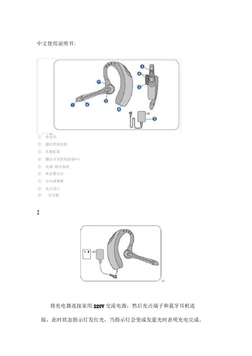
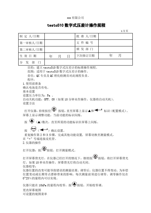
中文使用说明书:①吏克风②邇话羟制技钮③耳塞靳筒④邇话音星控制按钮+卜⑤电洒/静音按钮⑥秋态揩示灯⑦方向调整臂⑧充点端口⑨克电器I将充电器连接家用220V交流电源,然后充点端子和蓝牙耳机连接,此时状态指示灯发红光,当指示灯会变成发蓝光时表明充电完成。
耳机正常使用需要充电时间在20分钟到3小时,注意:不要在充电时使用耳机,也不要在使用过程中对耳机进行充电。
按住电源/静音按钮3秒钟以启动或关闭蓝牙耳机。
当蓝牙耳机启动时状态指示灯闪烁蓝光,当电池电力不足时指示灯闪烁红光。
皿在你使用您的蓝牙耳机之前,你必须将它和另一蓝牙设备进行对接,比如移动电话。
①启动两个蓝牙设备。
②同时按住蓝牙耳机的通话控制按钮和通话音量控制按钮的+号部位使耳机进入配对模式,当状态指示灯交替闪烁红光和蓝光时表明配对模式已经启动,可以松开按钮。
③打开您的移动电话菜单中的蓝牙搜索功能,直到屏幕上显示PLT 510, —般这个过程会在2分钟内完成。
④选择移动电话屏幕上显示的PLT 510进行下一步操作,当移动电话提示需要输入一个配对密码时输入0000。
一旦配对成功状态指示灯会闪烁蓝光,如果配对失败请继续重复以上配对步骤。
IV①接听和结束通话短按一下通话控制按钮(1秒以内)。
②使用语音拨号功能:按住通话控制按钮2秒钟时间直到您听到响声可以语音拨号。
③如果您正在用移动电话进行通话时想要转移到蓝牙耳机继续进行通话,只需短按一下通话控制按钮。
①在通话中,可以通过按通话音量控制按钮+/-对音量进行调节。
②在通话过程中短按电源/静音按钮一下,可以将麦克风静音,在静音状态下耳塞听筒会每30秒发出“滴滴”的声音两下,想要关闭静音状态只需再次短按电源/静音按钮一下。
- 1、下载文档前请自行甄别文档内容的完整性,平台不提供额外的编辑、内容补充、找答案等附加服务。
- 2、"仅部分预览"的文档,不可在线预览部分如存在完整性等问题,可反馈申请退款(可完整预览的文档不适用该条件!)。
- 3、如文档侵犯您的权益,请联系客服反馈,我们会尽快为您处理(人工客服工作时间:9:00-18:30)。
绪 言承蒙惠顾,购得AR-510打印机。
在使用本机前,请细阅这本用户手册,以便能正确使用。
并且请妥善保存这本手册,万一有不了解或故障时,这本手册会带给您很大的帮助。
AR-510打印机是得实集团与日本西铁城公司合作开发、生产的超高速24针平推式票据打印机。
AR-510采用高速打印头设计,打印速度高达188汉字/秒,打印针寿命3亿次,前后两种平推式进纸,1000万字符长寿命耐用大色带,GB18030中文大字符集硬字库及多款防改写数字、半角英数字及八款条形码打印,使AR-510在硬件方面别具特色。
在软件方面,AR-510秉承了得实系列打印机的高性能、高兼容性,可兼容所有STAR、EPSON和OKI 打印机,方便的自动撕纸功能及参数设置功能是得实打印机的特色。
打印机针调整和断针自动补偿功能是得实打印机的专利技术。
AR-510设计精美、外形精巧、功能齐全、用途广泛,是税务、银行、运输、医院、商业、POS系统等票据用户的极佳选择。
目录第1章安装打印机.....................................1-11.1开箱和检查......................................1-11.2放置打印机......................................1-21.3打印机部件......................................1-31.4安装和更换色带盒................................1-51.5打印机和主机连接................................1-81.6连接电源........................................1-91.7安装打印驱动程序...............................1-10第2章纸的安装和使用.................................2-12.1选纸............................................2-12.2调校打印头间隙..................................2-12.3装入单页纸......................................2-22.4装入链式纸......................................2-4第3章控制面板.......................................3-13.1按钮及其指示灯..................................3-13.2开机功能........................................3-43.3组合功能........................................3-7第4章参数设置.......................................4-14.1如何选择打印机参数设置..........................4-14.2如何进行参数设置................................4-24.3如何进行双向测试及纵向校正.....................4-184.4如何进行打印针自动调整设置.....................4-224.5如何进行打印针补偿设置.........................4-244.6票据通设置和使用...............................4-264.7如何进行用户调整设置...........................4-294.8如何恢复出厂参数设置...........................4-32第5章故障和保养.....................................5-15.1故障处理........................................5-15.2保养与维护......................................5-6第6章规格...........................................6-16.1打印机规格......................................6-16.2接口接头引脚....................................6-46.3字符集..........................................6-86.4控制码摘要表...................................6-146.4.1ESC/P和LQ仿真控制码摘要表..................6-146.4.2OKI仿真控制码摘要表........................6-18安全规范企业公开信息:1.售后服务请致电全国各地得实服务网点电话,或拨打:400-810-9998(手机)800-810-9998(免费)2.产品工作、待机、休眠及关闭状态的最大及最小能耗如下:产品使用状态最大能耗最小能耗工作时78W 10W待机8W 7W休眠7W 7W关闭小于0.1W 0注:只有当产品无任何外接输入电源时,才能实现零能耗。
3.如果用户需对产品性能升级或更换模块,请联系我们,我们将给您详细解答。
4.当您弃置达到使用寿命年限的针式打印机产品时,我们建议您将废弃产品返还给本公司或全国各地得实服务网点,由得实集团作统一处理,以保护生态环境。
5. 本产品能使用含50%回收纤维的打印纸进行打印。
第1章安装打印机1.1 开箱和检查打开纸箱,对照下图检查箱内部件和附件是否齐全。
如果有任何部件遗失,请与卖方联系。
注意:使用之前,请先取出打印头固定板,保留原包装盒及包装物材料以备以后使用。
*机器出厂时送纸旋钮未安装于机器上,请从缓冲泡沫上取出并安装 附件在安装打印机之前,首先要确定一个合适的地方放置打印机。
这里“合适的地方”是指:z请将打印机平放在工作台上。
z避免将打印机置于过热、过度潮湿和灰尘过多的地方。
z接上稳定电源,避免与电冰箱之类大功率或有干扰的电器同一电源。
z关掉打印机后才能拔掉插头,打印机应最好放置在接近插座的地方,便于使用。
z打印机应放置在走纸空间足够的地方。
z如果用打印机并行接口连接,确保电缆长度在2米范围内。
用RS-232C连接,可选SPC-32K转换器,连接距离可在15米以内。
要熟悉打印机部件及功能,请参阅下一页。
间隙调杆:控制打印色度,调校打印头间隙,以配合纸张厚度。
导 纸 板:调整单页纸的位置,便于打印机检查打印纸是否插入,保证正确安装。
入 纸 槽:插入单页纸。
打 印 头:24根打印针及其驱动部分组成。
面 盖:保护打印头及其它内部部件并降低噪音。
控制面板:表示打印机状态,可对打印机功能进行多种简易操作。
送纸调杆:该调杆有两个位置,向前用于链式纸,向后用于单页纸。
送纸旋钮:手动送纸。
电源开关:电源开或关。
色 带 盒:内装打印色带。
链 轮:控制链式纸移动。
电源 线: 连接打印机和电源插座。
接 口:连接计算机与打印机。
1.4 安装和更换色带盒注意:更换新色带盒之前,请先拿开旧色带盒。
安装和更换色带盒步骤如下:1、关掉打印机电源。
2、先把面盖揭起,如下图所示。
3、将间隙调杆拨至最大位置,以便打印头和打印辊之间的间隙处于最大值,即“换色带”的位置,如下图所示。
4、沿顺时针方向转动色带盒上的旋钮,确保色带已被拉紧。
5、将色带盒从机架两边的凹槽插入,使色带盒两边的卡扣卡在机架上,将色带夹在打印头和色带保护片中间,并转动色带盒上旋钮,使色带盒卡紧在机架上,如下图所示。
6、确保色带已夹在打印头和色带保护片中间,色带盒已固定在机架的适当位置上,如下图所示。
7、再次转动色带盒上旋钮,确保色带已被拉紧。
8、把面盖小心盖好。
打印机正常工作时,盖上面盖可以隔离灰尘,同时减低打印时产生的噪音,打开面盖仅是为了更换色带及进行调整。
9、将间隙调杆拨至原来的位置,以便打印头和打印辊的间隙恢复到原始状态。
1.5 打印机和主机连接使用标准并行接口电缆连接打印机和计算机,就PC或兼容计算机来说,即使用25芯D型插头连接计算机,并用另一端36芯Centronics插头与打印机相连,如果将打印机连到另外一种计算机上,请参阅接口配置。
请按如下步骤连接打印机与主机:1、关掉打印机及计算机电源。
2、按下图所示将接口电缆连到打印机上,确保插头插紧。
用接口两边的扣杆把电缆插头扣紧至听到接口电缆卡紧的响声。
3、将接口电缆另一端连到计算机上,连接步骤按主机手册指示。
注意:打印机开始工作时,确定计算机一端的接口电缆已经完全安装好。
将打印机插头插上时,请勿打开打印机电源。
如果打印机长时间不使用,请拔掉电源线。
1.6 连接电源连接电源线确保打印机及计算机关掉电源,从打印机背面将电源线另一端接到电源插座上。
开机和关机按下电源开关旁边标志的“I”处,即可打开打印机的电源。
按下电源开关旁边标志的“O”处,即可关掉打印机的电源。
1.7 安装打印驱动程序在安装打印机驱动程序之前,要把打印机与计算机正确连接好。
在Windows95/98/Me/2000/XP下安装驱动程序请按以下步骤安装打印机驱动程序:1、从“我的电脑”或“资源管理器”打开打印机文件夹。
2、在“打印机”窗口双击“添加打印机”图标。
3、在“添加打印机”向导窗口单击“下一步”按钮;开始安装打印机。
4、如果该打印机直接与计算机相连,请单击“本地打印机”;如果它与其他计算机相连,请单击“网络打印机”。
单击“下一步”按钮。
5、单击“从磁盘安装”按钮;把安装盘插入到选择好的驱动器,在“从磁盘安装”对话框输入安装的打印机驱动程序的名称。
(包括驱动器号和目录)并单击“确定”按钮。
出现“AR-510”打印机。
单击“下一步”按钮。
6、选择打印机端口;单击“下一步”按钮。
7、确定所安装的打印机是否为默认打印机后,单击“下一步”按钮。
8、确定是否打印测试页后,单击“完成”按钮。
9、安装打印机驱动程序结束。
安装完成后,所安装的打印机的图标将出现在打印机文件窗口。
检查和修改打印机驱动程序设置在开始打印之前,请检查纸张菜单和图形菜单中的打印机驱动程序设置是否适合您所希望打印的文件类型,必要时可修改设置。
完成改变后,单击“确定”按钮来应用设置,或单击“还原默认值”来恢复出厂设置。
按以下步骤来检查和修改打印机驱动程序设置:1、在桌面窗口,单击开始。