丹佛斯比例阀
样本 丹佛斯 电磁阀

波兰(Polski Rejestr Ststkow) 俄罗斯(MRS) 也可提供通过 UL 认证产品。
DKRCC.PD.BB0.B3.41 / 520H7191
参数表 技术数据
2
电磁阀,型号 EVR 2 − 40 NC/NO
制冷剂
R22/R407C、 R404A/R507 、R410A、R134a、R407A、 R23。如需使用其他 制冷剂,请洽询 Danfoss。
R404A/ R507 1.20 2.00 6.00 14.30 19.60 37.70 45.20 75.30 120.00 188.00
பைடு நூலகம்
液体和吸气名义制冷量的工况条件为:
蒸发温度 te = -10 °C 阀门前液体温度 tl = 25 °C 经过电磁阀压力降 ∆p = 0.15 bar
热气名义制冷量的工况条件为:
—
a.c./ d.c. 1/2 12 032F8095 032F1217 032F1218
—
a.c./ d.c. 5/8 16 032F8098 032F1214 032F1214
—
a.c./ d.c. 5/8 16 032F8101 032F1228 032F1228
—
a.c./ d.c. 5/8
—
d.c.
7/8
22
—
—
—
032F1274
a.c.
1 3/8 35
—
032F3267 032F3267
—
a.c./ d.c. 1 1/8
—
—
—
032F2200
a.c./ d.c. — 28
—
—
—
032F2205
丹佛斯动态压差平衡阀asv
通过先进的控制策略和优化设计,ASV在节 能环保方面表现更出色。
适应性更强
ASV适用于多种管道系统和压差范围,具有 更强的适应性。
维护更方便
ASV采用模块化设计,维护更换部件更为便 捷,降低了维护成本和时间成本。
03
CATALOGUE
ASV选型与安装指导
选型依据和建议
管道系统参数
经过ASV改造后,空调系统水力 平衡得到显著改善,室内温度分 布更加均匀,提高了人体舒适性 。
节能效果显著
通过实际运行数据对比,ASV改 造后的空调系统节能率达到20% 以上,显著降低了运行成本。
管理效率提高
ASV的智能化控制功能使得空调 系统管理更加便捷高效,减少了 人工维护成本。
05
CATALOGUE
应用范围广泛
丹佛斯动态压差平衡阀ASV可广泛应用于建筑、工业、市政等领域的水暖管道系统,为系统的稳定运行 和节能减排提供了有力保障。
未来研究方向探讨
智能化控制技术研究
多功能集成化设计
可靠性提升研究
拓展应用领域探索
随着物联网、云计算等技术的 发展,未来可以研究如何将智 能化控制技术应用于丹佛斯动 态压差平衡阀ASV,实现远程 监控、自动调节等功能。
功能
通过实时感知管道系统中的压差 变化,ASV能够自动调整阀门的 开度,从而维持稳定的压差,确 保系统的正常运行和高效能耗。
丹佛斯品牌背景
丹佛斯(Danfoss)是一家全球领先 的能源效率和环境优化解决方案提供 商,专注于为工业、商业和民用领域 提供高质量的产品和服务。
凭借多年的技术积累和市场经验,丹 佛斯在暖通空调、制冷、水处理、工 业自动化等领域拥有广泛的产品线和 解决方案。
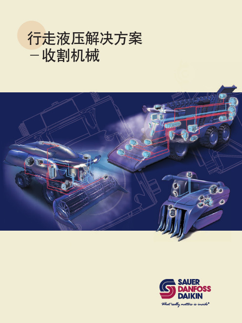
萨澳丹佛斯行走液压解决方案-联合收割机
+67㾘Ḑ
%'8/ %'8+ %'8+
/'8
᳔Ꮉय़˄0SD˅
᳔䕧ܹ䕀䗳˄USP˅
• 排量从10cc-32cc,变量泵与定量马达 • 一体式结构,结构紧凑节省安装空间 • 控制扭矩小,操作省力 • 集成补油泵 • 可选配集成过滤器 • 可集成旁通阀,用于短距离拖车 • 可集成过滤器
设计阶段
• 计算及元件选型 • 仿真及系统失效模式分析
样机验证
• 样机启动调试 • 现场真实工况测试 • 系统最优化分析及故障诊断
批量生产
• 最后检查 • 最终报告 • 相应文本整理 • 生产启动支持
转向系统
• 可应用于不同型号的联合收割机转向系统 • 转向性能客户化,且驾驶室噪音低和扭矩输入大,操作舒适 • 采用GPS技术和拉线传感器,实现自动转向控制 • 转向比可变,以适应不同工况下转向需求 • 不同排量定量泵或变量泵可选 • 优先阀可安装于不同位置 • 可实现手动紧急转向而不需紧急转向泵
HST 型号 泵排量 马达排量 输入转速
系统压力
输入功率 补油压力 重量
(最小) (额定) (最大) (额定) (最大)
产品参数表
单位 cm3/rev cm3/rev
min-1 min-1 min-1
BDU-10L 0-10 10 600 3600 3800
bar
150
bar
175
PS
5
bar
3
kg
去头 收割 清选 举升/筛选 升运 卸料 传送
系统示例
变量马达 (H1)
丹佛斯比例阀接线方法

丹佛斯比例阀接线方法嘿,朋友们!今天咱就来唠唠丹佛斯比例阀接线这档子事儿。
你说这丹佛斯比例阀啊,就像是机器世界里的小精灵,得给它接好线,它才能欢快地工作呢!那接线咋弄呢?听我慢慢道来。
首先呢,你得准备好工具,就像战士上战场得有趁手的兵器一样。
螺丝刀啊、剥线钳啊,这些可都不能少。
然后,找到比例阀上的接线端子,这就好比是找到小精灵的家。
看着那些小小的接线端子,可别小瞧它们,它们就像是电路世界的小入口,接对了路,一切都顺顺利利,接错了,那可就麻烦喽!就好像你本想去东边,结果走反了方向去了西边,能行不?把线的外皮剥开一点,露出里面的金属丝,这就像是给小精灵准备好礼物。
然后小心翼翼地把金属丝插进接线端子里,拧紧螺丝,就好像给小精灵关上家门,让它安心待在里面。
这时候你可能会问了,要是接错了咋办呀?嘿,那可就好比是走岔了路,得赶紧回头重新走啊!可不能马虎大意。
你想想看,要是接线没接好,这比例阀能好好工作吗?就像人要是腿不舒服,还能跑得快吗?所以啊,咱得认真对待,不能敷衍了事。
而且啊,在接线的过程中,还得注意安全。
电这玩意儿可不是好惹的,不小心碰到了,那可不得了。
就跟遇到一只小老虎似的,得小心应付。
接完线后,别着急,再检查检查,看看有没有松动的地方,有没有接错的地方。
就像出门前得照照镜子,看看自己穿戴整齐了没有。
总之呢,丹佛斯比例阀接线这事儿,说简单也简单,说难也难。
关键就看你用不用心,仔不仔细。
要是你认真对待,那它就能乖乖为你服务;要是你马马虎虎,那它可就没准给你闹出啥乱子来。
所以啊,朋友们,可别小瞧了这小小的接线工作,它可是关系到整个系统能不能正常运行的关键呢!大家都记住了吗?。
丹佛斯Danfoss静态平衡阀MSV-BD参数表-水力平衡

65 0.88 0.89 0.90 0.91 0.92 0.94 0.95
2)
100
1)
0.86 0.87 0.88 0.90 0.95 0.92 0.94
低于冰点 高于沸点
举例:所需流量= 30 m3/h 修正后的流量: 30 x 0.95 = 28 m3/h
阀门选型尺寸和预设定
举例: 已知最大流量 = 2.0 m3/h ∆pr = 15 kPa ∆pa = 45 kPa ∆pm =10 kPa ∆pi = ∆pa - ∆pr - ∆pm ∆pi = 45 kPa - 15 kPa - 10KPa = 20 kPa 在流量图上找到恰当的选型口径和预设定。 Q= 2.0 m3/h and ∆pi = 20 kPa 找到两条线的交点: 管道尺寸DN20,预设定值4.2-见11页 预设定也可以通过公式计算:
最大工作静压 测试静压 阀两端最大压差 最高水温 最低水温 冷却液
HEC-HB
VDB4C341 © Danfoss03/2012
3
参数表
静态平衡阀 LENO™ MSV-BD
连接
在装配阀门之前,安装人员必须保证管路系统 的清洁以及: 1.阀门可以360º转动(如果使用的是螺纹连接)。 2.阀门安装方向应与阀体水流方向箭头一致。 卸下手柄 1.将手柄调节到0/0刻度上。 2.松开设定锁(绿色)。 3.旋松螺帽。 手柄的校准 重新装配前,确保手柄设定值到0/0刻度上。 对于外螺纹的DN 15-20阀门 丹佛斯为钢管、铜管和PEX管提供了完整的一 套压紧连接件。
设计
12 8 10
14 9 6
11 7
13
1. 阀体 2. 球体 3. 球座 4. 支撑螺杆 5. 调节衬套 6. 关断衬套 7. 阀顶盖 8. 阀锥头 9. 阀锥 10. 旋转锁 11. 泄水 12. 手柄 13. 旋转测量装置 14. 测量接头
丹佛斯Danfoss动态压差平衡阀ASV参数表-水力平衡
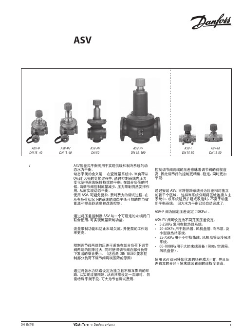
图 4 ASV用于地板采暖系统中分集水器前
ASV 阀用于地板采暖系统。为实现对每个环路的 流量限制,应将带有预设定的分集水器与 ASV-PV 阀提供的恒定压差控制配合使用。或者通过使用
具有设定功能 ASV-I 实现对整个分集水器的流量 限制。
如需不同的设定压差,ASV-PV 的设定压差具有数 个的可选范围。由于尺寸紧凑,ASV 动态压差平衡 阀易于安装于挂墙的分集水器安装盒内。
型号
备注
螺纹尾管(1 件)
焊接尾管(1 件)
连接至管道 R½ R¾ R1 R 1¼ R 1½
R2
DN 15 DN 20 DN 25 DN 32 DN 40
DN 50
注意: ASV-PV DN 50 (2½”) 和 ASV-I/M DN 50 (2¼”) 的接头口径不同。 1) 与 ASV-PV DN 50 阀配套使用 2) 与 ASV-I 和 ASV-M DN 50 配套使用。
ASV-P 阀为固定压差设定(10KPa)。
ASV-PV 阀可设定为不同范围压差设定: • 5-25KPa 常用在散热器系统, • 20-40KPa 用于散热器、风机盘管、冷吊顶、及
小型换热站系统, • 35-75KPa 用于小型换热站、风机盘管及冷吊顶
系统, • 60-100KPa 用于大的末端设备(例如:空调箱、
22
VD.A1.T8.41 © Danfoss 07/2013
DH-SMT/SI
DH-SMT/SI
VD.A1.T8.41 © Danfoss 07/2013
3
参数表 描述 / 应用 (续)
动态压差平衡阀 ASV
参数表
保温材料
图 +5 ASV 用于风机盘管系统
比例阀的工作原理

比例阀的工作原理
比例阀是一种常用的控制阀,其工作原理是通过调节流体通过阀门的截面积来实现流量的控制。
具体工作原理如下:
1. 内部结构:比例阀由阀体、阀芯和驱动器组成。
阀体内部包含进口和出口通道,以及与通道连接的阀座。
阀芯则位于阀体内部,可以在阀座上移动。
2. 运动控制:比例阀的阀芯受到外部驱动器的控制,驱动器可以通过电流或压力信号来控制阀芯的位置。
当驱动器接收到输入信号时,会相应地调整阀芯的位置。
3. 流体控制:通过调节阀芯的位置,比例阀可以控制流体通过阀门的截面积。
当阀芯离开阀座时,流体可以通过阀门的截面积增大,从而增加流量;反之,阀芯靠近阀座时,截面积减小,流量减小。
4. 反馈控制:为了确保阀门的稳定运行,比例阀通常配备反馈控制功能。
这意味着阀芯的位置可以被检测并反馈给驱动器,使其能够实时调整阀芯的位置,并保持所需的流量控制。
通过以上工作原理,比例阀可以精确地控制流体流量,广泛应用于工业自动化系统中,如液压系统、气动系统、流体控制系统等。
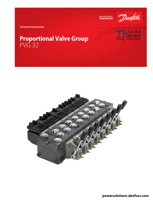
丹弗斯PVG32系列比例多路阀样本
丹弗斯PVG32系列比例多路阀样本丹弗斯(Danfoss)PVG32系列比例多路阀是一种高性能的液压控制阀,广泛应用于工程机械、农业机械、航空机械等领域。
PVG32系列比例多路阀是基于丹弗斯先进的闭环控制技术,采用比例电磁阀和先进的电子控制器,具有精确的控制能力和高可靠性。
本文将详细介绍PVG32系列比例多路阀的特点、应用领域和技术指标。
PVG32系列比例多路阀的特点:1.高精度控制:PVG32系列比例多路阀采用先进的比例电磁阀和电子控制器,可以实现精确而稳定的液压控制,满足工程机械和其他应用中对精度要求高的场景。
2.良好的可调性:PVG32系列比例多路阀具有广泛的调节范围,可以实现多种不同的流量和压力控制需求。
通过电子控制器的参数调整,可以轻松实现控制参数的改变。
3.高性能比例电磁阀:PVG32系列比例多路阀采用了先进的比例电磁阀技术,具有快速的响应速度和稳定的控制特性,能够快速实现液压控制信号的转换。
4.多种控制方式:PVG32系列比例多路阀支持多种不同的控制模式,包括手动操作、电流控制和压力控制等,满足不同工作场景的需求。
5.高可靠性:PVG32系列比例多路阀采用先进的电子控制技术和优质的材料制造,具有较高的可靠性和耐用性,适用于各种恶劣的工作环境。
PVG32系列比例多路阀的应用领域:1.工程机械:PVG32系列比例多路阀广泛应用于各种工程机械设备,如挖掘机、装载机、推土机等。
可以实现对液压系统的精确控制,提高机械设备的操作性能和效率。
2.农业机械:PVG32系列比例多路阀也适用于农业机械领域,如拖拉机、农用挖掘机等。
可以实现对农业机械设备的液压系统进行精确控制,提高农机设备的工作效率和稳定性。
3.航空机械:PVG32系列比例多路阀还可以用于航空机械领域,如飞机起落架、缝翼系统等。
可以实现对航空机械设备的液压系统进行精确控制,提高航空机械设备的安全性和可靠性。
PVG32系列比例多路阀的技术指标:1. 工作压力:最高工作压力为350 bar。
丹弗斯PVG32系列比例多路阀样本
Revision history Table of revisionsTechnical InformationPVG 32 Proportional Valve Group2 | © Danfoss | August 2017520L0344 | BC00000038en-US0802General descriptionFeatures of PVG 32...........................................................................................................................................................................5PVG modules .....................................................................................................................................................................................5PVP, pump side modules..........................................................................................................................................................5PVB, basic modules.....................................................................................................................................................................5Actuation modules.....................................................................................................................................................................6Remote control units ......................................................................................................................................................................6PVG 32 with open center PVP......................................................................................................................................................7PVG 32 with closed center PVP....................................................................................................................................................8PVG 32 sectional view.....................................................................................................................................................................9Load sensing for variable displacement pump supply.......................................................................................................9Safety in applicationControl system example..............................................................................................................................................................12Examples of wiring block diagram.....................................................................................................................................14FunctionLoad sensing controls...................................................................................................................................................................16LS control with bleed orifice (do not use with PVG valves).......................................................................................16Integral PC function.................................................................................................................................................................16Load sensing system characteristics:.................................................................................................................................16Remote pressure compensated controls..............................................................................................................................16Remote pressure compensated system characteristics:............................................................................................17Typical applications for remote pressure compensated systems:..........................................................................17PVG 32 main spool with pressure compensated control................................................................................................17Pressure compensated system characteristics..............................................................................................................18Typical applications for pressure compensated systems...........................................................................................18PVPC adapter for external pilot oil supply............................................................................................................................18PVPC with check valve for open center PVP...................................................................................................................18PVPC without check valve for open or closed center PVP.........................................................................................19PVMR, friction detent....................................................................................................................................................................21PVMF, mechanical float position lock.....................................................................................................................................21PVBS, main spools for flow control (standard)....................................................................................................................21PVBS, main spools for flow control (linear characteristic)...............................................................................................21PVBS, main spools for pressure control.................................................................................................................................22Background.................................................................................................................................................................................22Principle.......................................................................................................................................................................................22Application..................................................................................................................................................................................23Sizing.............................................................................................................................................................................................23Limitation....................................................................................................................................................................................24PVPX, electrical LS unloading valve.........................................................................................................................................24PVG 32 technical dataPVH, hydraulic actuation.............................................................................................................................................................26PVM, mechanical actuation........................................................................................................................................................26PVE, electrical actuation..............................................................................................................................................................26PVPX, electrical LS unloading valve.........................................................................................................................................29Electrical actuationElectrical control of PVG..............................................................................................................................................................30Closed loop control.......................................................................................................................................................................31PVEO...................................................................................................................................................................................................32PVEM...................................................................................................................................................................................................32PVEA, PVEH, PVES, PVEU..............................................................................................................................................................33PVEP....................................................................................................................................................................................................33PVED-CC and PVED-CX.................................................................................................................................................................33PVHC...................................................................................................................................................................................................34Technical characteristicsGeneral...............................................................................................................................................................................................36PVP, pump side module.. (36)Technical InformationPVG 32 Proportional Valve GroupContents© Danfoss | August 2017520L0344 | BC00000038en-US0802 | 3PVB, basic modules oil flow characteristics..........................................................................................................................36Pressure-compensated PVB, open center PVP ..............................................................................................................37PVB without pressure compensation, open center PVP.............................................................................................38PVB without pressure compensation, closed center PVP..........................................................................................39PVLP, shock and PVLA, suction valves...............................................................................................................................41Pressure build-up for pressure controlled spools.........................................................................................................41Pressure control spool flow characteristics..........................................................................................................................41Examples of how to use the characteristics for pressure control spools...................................................................42Characteristics for float position main spools (43)Hydraulic systemsManually actuated PVG 32 – fixed displ. pump..................................................................................................................45Electrically actuated PVG 32 – variable displ. pump.........................................................................................................46Other operating conditionsOil.........................................................................................................................................................................................................47Particle content, degree of contamination...........................................................................................................................47Filtration............................................................................................................................................................................................47DimensionsPVM, control lever positions......................................................................................................................................................50Surface treatment.. (51)Modules symbols, description and code numbersPVP, pump side modules.............................................................................................................................................................52PVB, basic modules........................................................................................................................................................................54PVLA, suction valve (fitted in PVB)...........................................................................................................................................56PVLP, shock and suction valve (fitted in PVB)......................................................................................................................56PVM, mechanical actuation........................................................................................................................................................57PVH, hydraulic actuation.............................................................................................................................................................58PVS, end plate..................................................................................................................................................................................58PVAS, assembly kit.........................................................................................................................................................................58PVPX, electrical LS unloaded valve..........................................................................................................................................58PVPC, plug for external pilot oil supply..................................................................................................................................59Module selection chartStandard FC spools........................................................................................................................................................................60Standard FC spools, hydraulic actuation...............................................................................................................................61FC spools for mechanical float position, PVMF...................................................................................................................61FC spools for friction detent, PVMR.........................................................................................................................................62FC spools with linear flow characteristic ..............................................................................................................................62Standard PC spools .......................................................................................................................................................................63Standard PC spools, hydraulic actuation...............................................................................................................................64PVB, basic valves.............................................................................................................................................................................65PVP, pump side module..............................................................................................................................................................66PVE, electrical actuation..............................................................................................................................................................68Order specificationStandard and option assembly.................................................................................................................................................70Reordering........................................................................................................................................................................................70Pressure setting limits..................................................................................................................................................................70PVG 32 specification sheet (72)Technical InformationPVG 32 Proportional Valve GroupContents4 | © Danfoss | August 2017520L0344 | BC00000038en-US0802PVG 32 is a hydraulic load sensing valve designed to give maximum flexibility. From a simple load sensing directional valve, to an advanced electrically controlled load-independent proportional valve.The PVG 32 modular system makes it possible to build up a valve group to meet requirements precisely.The compact external dimensions of the valve remain unchanged whatever combination is specified.Features of PVG 32•Load-independent flow control:‒Oil flow to an individual function is independent of the load pressure of this function‒Oil flow to one function is independent of the load pressure of other functions •Good regulation characteristics •Energy-saving•Up to 12 basic modules per valve group •Several types of connection threads •Low weight•Compact design and installationPVG modulesPVP, pump side modules•Built-in pressure relief valve •Pressure gauge connection•Versions:‒Open center version for systems with fixed displacement pumps‒Closed center version for systems with variable displacement pumps ‒Pilot oil supply for electrical actuator built into the pump side module ‒Pilot oil supply for hydraulic actuation built into the pump side module ‒Versions prepared for electrical LS unloading valve PVPXPVB, basic modules•Interchangeable spools•Depending on requirements the basic module can be supplied with:‒Integrated pressure compensator in channel P‒Load holding check valve in channel P ‒Shock/suction valves for A and B portsTechnical InformationPVG 32 Proportional Valve GroupGeneral description© Danfoss | August 2017520L0344 | BC00000038en-US0802 | 5‒LS pressure limiting valves individually adjustable for ports A and B ‒Different interchangeable spool variants‒All versions suitable for mechanical, hydraulic and electrical actuationActuation modulesThe basic module is always fitted with mechanical actuator PVM and PVMD, which can be combined with the following as required:•Electrical actuator (11 - 32 V ===):‒PVES – proportional, Super‒PVEH – proportional, High performance ‒PVEH-F – proportional high performance, Float ‒PVEA – proportional low hysteresis ‒PVEM – proportional, Medium performance ‒PVEO – ON/OFF‒PVEH-U/PVES-U – proportional, voltage control, 0-10 V ‒PVED-CC – Digital CAN controlled J1939/ISOBUS ‒PVED-CX – Digital CAN controlled CANopen X-tra safety ‒PVEP – PWM voltage controlled (11-32 V)‒PVHC – High Current actuator for PVG•PVMR, cover for Mechanical detent •PVMF, cover for Mechanical Float •PVH, cover for Hydraulic actuationRemote control units•Electrical remote control units:‒PVRE, PVRET ‒PVREL ‒PVRES ‒Prof 1‒Prof 1 CIP ‒JS120‒JS1000 Ball grip ‒JS1000 PRO grip ‒JS2000‒JS6000‒JS7000•Hydraulic remote control unit: PVRHHTechnical InformationPVG 32 Proportional Valve GroupGeneral description6 | © Danfoss | August 2017520L0344 | BC00000038en-US0802Electrical and hydraulic remote control unitsPVRE, electrical control unit, 162F…PVREL, electrical control unit, 155U…PVRH, hydraulic control unit, 155N…155N0003 155N0001155N0004 155N0005 155N0002PVG 32 with open center PVPPVG 32 with open center PVP (fixed displacement pump) and PVB with flow control spool.When the pump is started and the main spools in the individual basic modules (11) are in the neutral position, oil flows from the pump, through connection P, across the pressure adjustment spool (6) to tank.The oil flow led across the pressure adjustment spool determines the pump pressure (stand-by pressure).When one or more of the main spools are actuated, the highest load pressure is fed through the shuttle valve circuit (10) to the spring chamber behind the pressure adjustment spool (6), and completely or partially closes the connection to tank to maintain pump pressure.Pump pressure is applied to the right-hand side of the pressure adjustment spool (6).The pressure relief valve (1) will open should the load pressure exceed the set value, diverting pump flow back to tank.In a pressure-compensated basic module the compensator (14) maintains a constant pressure drop across the main spool – both when the load changes and when a module with a higher load pressure is actuated.With a non pressure-compensated basic module incorporating a load drop check valve (18) in channel P,the check valve prevents return oil flow.The basic module can be supplied without the load drop check valve in channel P for functions with over-center valves.The shock valves PVLP (13) with fixed setting and the suction valves PVLA (17) on ports A and B are used for the protection of the individual working function against overload and/or cavitation.Technical InformationPVG 32 Proportional Valve GroupGeneral description© Danfoss | August 2017520L0344 | BC00000038en-US0802 | 7An adjustable LS pressure limiting valve (12) can be built into the A and B ports of pressure-compensated basic modules to limit the pressure from the individual working functions. Please see the sectional drawing PVG 32 sectional view on page 9 below for better understanding of this example.The LS pressure limiting valves save energy compared with the shock valves PVLP:•with PVLP all the oil flow to the working function will be led across the combined shock and suctionvalves to tank if the pressure exceeds the fixed setting.•with LS pressure limiting valves an oil flow of about 2 l/min [0.5 US gal/min] will be led across the LSpressure limiting valve to tank if the pressure exceeds the valve setting.PVG 32 with closed center PVPPVG 32 with closed center PVP (variable displacement pump) and PVB with flow control spool.In the closed center version of PVP an orifice (5) and a plug (7) have been fitted instead of the plug (4).This means that the pressure adjustment spool (6) will only open to tank when the pressure in channel P exceeds the set value of the pressure relief valve (1).In load sensing systems the load pressure is led to the pump control via the LS connection (8).In the neutral position the pump load sense control sets the displacement so that leakage in the system is compensated, to maintain the set stand-by pressure.When a main spool is actuated the pump load sense control will adjust the displacement so that the set differential pressure (margin) between P and LS is maintained.The pressure relief valve (1) in PVP should be set at a pressure of approx. 30 bar [435 psi] above maximum system pressure (set on the pump or external pressure relief valve).Technical InformationPVG 32 Proportional Valve GroupGeneral description8 | © Danfoss | August 2017520L0344 | BC00000038en-US0802PVG 32 sectional viewPVPPVBPVB1. Pressure relief valve11. Main spool2. Pressure reduction valve for pilot oil supply 12. LS pressure limiting valve3. Pressure gauge connection 13. Shock and suction valve, PVLP4. Plug, open center 14. Pressure compensator5. Orifice, closed center 15. LS connection, port A6. Pressure adjustment spool 16. LS connection, port B7. Plug, closed center 17. Suction valve, PVLA8. LS connection 18. Load drop check valve9. LS signal 19. Pilot oil supply for PVE10. Shuttle valve20. Maximum oil flow adjustment screws for A/B portsLoad sensing for variable displacement pump supplyThe pump receives fluid directly from the reservoir through the inlet line. A screen in the inlet lineprotects the pump from large contaminants.Technical InformationPVG 32 Proportional Valve GroupGeneral description© Danfoss | August 2017520L0344 | BC00000038en-US0802 | 9The pump outlet feeds directional control valves such as PVG-32, hydraulic integrated circuits (HIC), and other types of control valves.The PVG valve directs and controls pump flow to cylinders, motors and other work functions. A heat exchanger cools the fluid returning from the valve. A filter cleans the fluid before it returns to the reservoir.Flow in the circuit determines the speed of the actuators. The position of the PVG valve spool determines the flow demand. A hydraulic pressure signal (LS signal) communicates demand to the pump control.The pump control monitors the pressure differential between pump outlet and the LS signal, and regulates servo pressure to control the swashplate angle. Swashplate angle determines pump flow.Actuator load determines system pressure. The pump control monitors system pressure and will decrease the swashplate angle to reduce flow if system pressure reaches the pump control setting.A secondary system relief valve in the PVG valve acts as a back-up to control system pressure.Pictorial circuit diagramTechnical InformationPVG 32 Proportional Valve GroupGeneral description10 | © Danfoss | August 2017520L0344 | BC00000038en-US0802Safety in applicationAll types of control valves (incl. proportional valves) can fail, thus the necessary protection against theserious consequences of function failure should always be built into the system. For each application anassessment should be made for the consequences of pressure failure and uncontrolled or blockedmovements. To determine the degree of protection that is required to be built into the application,system tools such an FMEA (Failure Mode and Effect Analysis) and Hazard and Risk Analysis can be used.FMEA – IEC EN 61508FMEA (Failure Mode and Effect Analysis) is a tool used for analyzing potential risks. This analyticaltechnique is utilized to define, identify, and prioritize the elimination or reduction of known and/orpotential failures from a given system before it is released for production. Please refer to the standard IECFMEA 61508.Hazard and risk analysis ISO 12100-1/14121This analysis is a tool used in new applications as it will indicate whether there are special safetyconsiderations to be met according to the machine directives EN 13849. Dependent on the determinedlevels conformity this analysis will detirmine if any extra requirements for the product design,development process, production process or maintenance, example the complete product life cycle.W WarningAll brands and all types of directional control or proportional valves, which are used in many differentoperation conditions and applications, can fail and cause serious damage.Analyze all aspects of the application. The machine builder/system integrator alone is responsible formaking the final selection of the products and assuring that all performance, safety and warningrequirements of the application are met. The process of choosing the control system and safety levels isgoverned by the machine directives EN 13849 (Safety related requirements for control systems).Control system exampleExample of a control system for manlift using PVE Fault monitoring input signals and signals from external sensors to ensure the PLUS+1® maincontrollers correct function of the manlift.Safety in applicationElectrical block diagram for the above illustrationWWarningIt is the responsibility of the equipment manufacturer that the control system incorporated in the machine is declared as being in conformity with the relevant machine directives.PVG 32 – mainly used in system with fixed displacement pumps:•PVSK, commonly used in crane application - full flow dump •PVPX, LS dump to tankPVG 100 – alternative LS dump or pilot supply disconnect:•PVPP, pilot oil supply shut off•External cartridge valve connecting LS pressure or main pressure to tank PVG 120 – pump disconnect / block for variable pumps:Safety in applicationSafety in application•PVPE, full flow dump for the PVG 120•External cartridge valve connecting LS pressure to tankExamples of wiring block diagramExample of a typical wiring block diagram using PVEH with neutral power off switch and fault monitoringoutput for hydraulic deactivation.A– Emergency stop / man present switchB– PVE Fault monitoring signalsC– Neutral signal detection.D– Hydraulic deactivationSystem Control Logic e.g. PLUS+1® for signal monitoring and triggering signal for deactivation of thehydraulic system.W WarningIt is the responsibility of the equipment manufacturer that the control system incorporated in themachine is declared as being in conformity with the relevant machine directives.。
丹佛斯电动调节阀介绍

Date
筑
龙 网
ww
w.
丹佛斯(上海)自动控制有限公司
zh
ul
on g.
DANFOSS
co
m
on g.
1、定义:阀门两端的压差为 1bar 时,阀门全开时流经阀门的流量,以 m3/h计。
co
阀门的基本概念 阀门的流通能力-kv
kv Q Δp
流量:
m
[m 3 / h]
[ bar ] Q k v
筑
龙 网
•自检: 驱动器第一次上电后会自动自检;任何时候按Reset键均可进行自检(驱动 器用于其他阀体时;手动操作以后)
ww
w.
co
1 3
•接线
SN = 公共线 SP = 电源 (-15% +10% 24Vac) Y = 阀位给定信号 = 驱动轴向伸出方向运动 = 驱动轴向收缩方向运动
X = 阀位反馈信号
co
94,85% 94,77% 94,69% 94,93% 94,69% 94,85% 94,77% 94,69% 94,93% 94,69% 94,85% 94,77% 95,69% 95,22% 95,66%
0,63 1
1,3
on g. ul zh w.
LO
1,6
2,05
2,5
3,25
4
5,15
阀权度的定义:
Δpsmax:系统的总压降
Date
筑
龙 网
ww
w.
zh
ul
on g.
p p a v100 v100 pv0 psmax
Δpv0:
阀门全关时阀上的压降
co
萨澳(SAUER DANFOSS)全系列产品介绍

转角传感器
控制手柄 (JS6000)
转向器 (OSPC LS) SASA
控制器 (PLUS+1™)
比例阀组 (PVG)
变量泵 (45系列)
CAN 总线
轮式装载机转向系统
工作系统
对于工作系统,萨澳-丹佛斯的解决方案不胜枚举。比如,我们所提供的人体工程学手柄,极大改善了操作舒
适度;利用LS技术,可以起到节能作用;不同的控制模式可供操作人员选择;零泄漏插装阀模块可选;通过
终端设备 (DP630)
摄像头 (CCC102)
传送
清选
马达
(OMH, OMP, OMS, OMV, OMR)
பைடு நூலகம்
比例阀组 (PVG32)
手柄 (JS1000)
拉线传感器
控制器 (PLUS+1™)
变量马达 (H1B)
ASC 防打滑阀
程序调试工具
前进/停止/ 后退
甜菜收割机控制系统
柱塞泵 (H1)
5
One of the Industry’s Broadest Product Portfolios
工厂位于
Nordborg 丹麦
工厂位于
Neumünster 德国
工厂位于
Shanghai 中国
工厂位于
Osaka 日本
全球网络
工厂位于
Ames, IA 美国
萨澳-丹佛斯总部 萨澳-丹佛斯工厂 萨澳-丹佛斯-大金总部 萨澳-丹佛斯-大金工厂
工厂
Älmhult, 瑞典 Ames, IA, 美国 Bielany Wroclawskie, 波兰 Bologna, 意大利 Caxias do Sul, 巴西 Dubnica nad Váhom, 斯洛伐克 Easley, SC, 美国 Freeport, IL, 美国 Kaiserslautern, 德国 Minneapolis, MN, 美国
丹福斯 Vickers KB比例阀概述说明书
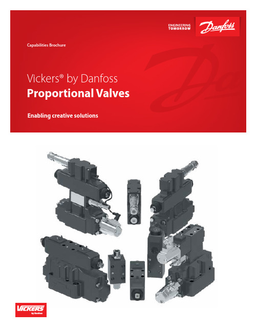
Demanding applications call for Vickers by DanfossWith a wide range of markets serviced, our KB proportional valves are enabling truly creative solutions.As technology continues to improve, so does the engineering Danfoss builds into its proportional valves. Vickers KB proportional valves are manufactured, sold, and supported throughout the world with the high quality you expect from Danfoss. 1. Control function - direction, flow, and pressure2. Performance levels - standardhigh, and servo3. Onboard electronics – with (KB model) and without (K model)4. Complete size range – D03-D10 (NG6-NG32)5. Wide variety of supportingelectronics Integrated amplifiers mean“plug and play”Integrated amplifiers are factorypreset and eliminate any adjustmentof gain, dead-band compensation,or dither required for separatecard and valve combinations. Plusthey eliminate the need for fieldadjustments and separately wired andmounted. Replacement valves can befitted without adjusting or changingthe control signals.New design means newapplicationsWith Vickers by Danfoss, KBproportional valves design engineersnow have a new generation ofintegrated valves that redefine andexpand industrial application designcapabilities. Vickers proportionalvalves are much easier to install thanprevious models using separate driveamplifiers. The only electrical inputsrequired are a power supply and acommand signal.Built to lastFor durability, you cannot beata KB proportional valve. Theamplifier is housed in a durablemetal enclosure, sealed againstenvironmental contaminates such ascutting fluid spray, water, and fluidwash down. Seven-pin electricalmating connectors are supplied asstandard. They are reliable, rugged,and provide easy access for testequipment.Consistency of quality is assured withthe KB proportional valve. Each valve/amplifier combination is tested andcalibrated as a total assembly with avariation of less than 5% from valveto valve. You can trust Vickers KBproportional valves to do the job asspecified and perform consistentlyand reliably for years.Rubber press Entertainment Primary metal Die castingProportional valve application matrixThe matrix to the right provides guidance for many industrial applications. Locate anapplication similar to yours, then read therecommended Valve Performance Level(Standard, High, or Servo Performance) atthe top and the ISO Valve Size (Size 3, 5, 7, 8,or 10) on the right side.The matrix uses “Frequency Response”as the primary determinant forvalve performance. This is not theonly parameter of importance in allapplications, but it does serve as a goodfirst reference.For example:Sawmill Setworks applications generallyrequire Servo Performance type valves. Thevalve size could be either a Size 5 or a Size 7depending upon the flow requirements of theapplication.500(1892) 400(1514) 300(1135) 200(757) 100(378) 70(265) 50(189) 40(151) 3020(76) 10(37) 7543210.7(2.6) 0.5(1.9) 0.40.3(1.1)0.2(0.76) Frequency at 90°Phase Lag (Hz) 35 7 8 10F l o w a t 1000 P S I P r e s s u r eG P M (L P M ) I S O V a l v e S i z e Valve Performance LevelPress Paper machine Machine toolCeramic pressSpecifications, features, and benefits of KB prop valvesOBE proportional valve comparisonFlow capability Frequency response GPM(US) LPM 0Hz Red fonts mean Danfoss’ product superiority over competitors.* Digital OBE valve: KBD(T)G4V, KBDG5V, KBFDG5V, KBX(C)G, KBCG, *IP65 on limited number of familitiesProportional directional valve with on-board-electronics (OBE)Proportional directional valve without on-board-electronics (Non-OBE)Amplifier (Euro card mounting)Amplifier (Din-plug mounting)Functional module (Din-rail mounting)Others Notes:A - with 2 rampsB - A plus on-board command inputsC - B plus additional 2 rampsD - C plus PID moduleE - A plus strip guidance module F- A plus CNC adaptation moduleProportional pressure relief valve familyEHST-3KBCG-6KCG-8Proportional pressure reducing valve familyKBX(C)G-6KBX(C)G-8KX(C)G-6KX(C)G-8 Proportional throttle slip-in valve family – with main stage LVDT feedbackValvistor – proportional throttle slip-in cartridge valve familyProduct and system descriptionBenefitsHigh bending speed, with precise control of bending depth, results in greater productivity. The design of the safety system blocks reduces production and maintenance costs.In order to improve productivity and quality, it is critical that the plasticizing process be precisely controlled. It requires accurate, repeatable, and smooth transition from velocity into pressure regulation. It is also imperative to achieve smooth, quick, and precise clamping movement.Product and system descriptionServo performance proportional valves K(B)S/ HDG and high performance K(B) FDG families with tailored spool design, are the answer for meeting the extremely demanding injection and clamping control requirements. They have an excellent dynamic capability of closed loop control on pressure, position, and velocity. BenefitsReduced cycle time and costs, with improved process control. One valve with a specially designed spool does all five critical controls of plasticizing, injection speed, holding pressure, decompression, worm return, and suck-back pressure. The “valve enable” feature on the KB line can be used to easily achieve interlock function.Highly accurate positioning, repeatability of machining cycles, and precise synchronization control of cylinders during the closing movement of the bending tool, are prerequisites of the hydraulic control system.By using two K(B)F/SDG4V proportional valves for small tonnage machines, or two K(B) HDG5V valves for large tonnage machines in closed loops, Vickers valves provide the solution to this very demanding application. System control blocks provide full compliance to safety regulations.Productivity is king. This transformsto the requirements of overallmachine reliability and durability,and precise control, and shortcycle time. Harsh environment isanother challenge for proportionalvalves mounted on the machines;robustness against shock,vibration, EMC, dirt, and moistureis a must.Product and systemdescriptionServo performance proportionalvalves KBS/HDG, with fullyencapsulated OBE (EN90version), provide extremelyreliable protection in conditionof vibrations and shock.Valves with zero lap spool andgrounded spool/sleeve pilotstage are characterized by theirhighdynamic performance— withlow hysteresis and high responsesensitivity— to achieve accuratepositioning control and speedcontrol.BenefitsOnboard Electronics (OBE) valvesfeature “plug and play” to savewiring hassle and tuning time. IP65 & 67 environment protectionprovide “best in industry”protection against moisture tomake sure the proportional valveswork reliably. When coupledwith a Vickers servo cylinder,the proportional valves can bemounted directly onto the cylinderto become a servo actuatorpackage.Wind power turbine control is avery demanding application thatrequires proportional valves tobe extremely reliable and durabledue to the nature of continuousproduction process. At the heartof advanced wind turbines is ahydraulic control system thatcontrols the pitch angle of theturbine blades, hence controllingthe speed and power production.Challenges are closed looppositioning control for precisepitch angle, and low and highambient temperatures in extremelyharsh environments.Product and systemdescriptionCoupled with servo cylinders,Vickers high performanceproportional valves KBFDG providea compact, rugged, and reliablepackage solution.BenefitsDigital Onboard Electronics(OBE) valves feature presetting theparameters with programming,which results better reproducibilityand repeatability. Failsafe featureprevents the equipment frombeing damaged. IP 65 and 67protection ratings mean Vickersvalves provide better resistance tomoisture than any competitors.Primary applicationsPress brake Injection molding machine Sawmill Wind power© Danfoss | Power Solutions | May 2023AD426931590930en-000101Any information, including, but not limited to information on selection of product, its application or use, product design, weight, dimensions, capacity or any other technical data in product manuals, catalogues descriptions, advertisements, etc. and whether made available in writing, orally, electronically, online or via download, shall be considered informative, and is only binding if and to the extent, explicit reference is made in a quotation or order confirmation. Danfoss cannot accept any responsibility for possible errors in catalogues, brochures, videos and other material. Danfoss reserves the right to alter its products without notice. This also applies to products ordered but not delivered provided that such alterations can be made without changes to form, fit or function of the product. All trademarks in this material are property of Danfoss A/S or Danfoss group companies. Danfoss and the Danfoss logo are trademarks of Danfoss A/S. All rights reserved.Danfoss Power Solutions, Nordborgvej 81, 6430 Nordborg, Denmark, Tel. +45 74 88 22 22, Fax +45 74 65 25 80 ,E-mail:****************。
PVG16
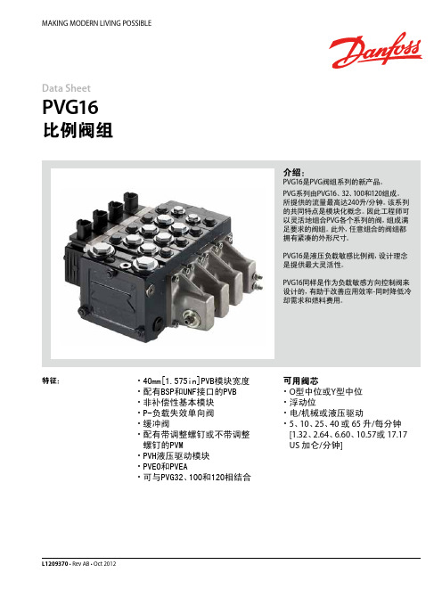
Data SheetPVG16比例阀组介绍:PVG16是PVG阀组系列的新产品。
PVG系列由PVG16、32、100和120组成。
所提供的流量最高达240升/分钟。
该系列的共同特点是模块化概念。
因此工程师可以灵活地组合PVG各个系列的阀,组成满足要求的阀组。
此外,任意组合的阀组都拥有紧凑的外形尺寸。
PVG16是液压负载敏感比例阀,设计理念是提供最大灵活性。
PVG16同样是作为负载敏感方向控制阀来设计的,有助于改善应用效率-同时降低冷却需求和燃料费用。
特征:・ 40mm[1.575in]PVB模块宽度・ 配有BSP和UNF接口的PVB・ 非补偿性基本模块・ P-负载失效单向阀・ 缓冲阀・ 配有带调整螺钉或不带调整螺钉的PVM・ PVH液压驱动模块・ PVEO和PVEA・ 可与PVG32、100和120相结合可用阀芯・ O型中位或Y型中位・ 浮动位・ 电/机械或液压驱动・ 5、10、25、40 或 65 升/每分钟 [1.32、2.64、6.60、10.57或 17.17 US 加仑/分钟] MAKING MODERN LIVING POSSIBLEL1209370 • Rev AB • Oct 2012丹佛斯动力系统(上海)有限公司中国 上海 浦东新区 金桥出口加工区 金海路1000号,22号楼 邮政编码:201206 电话:021-3418 5200 传真:021-6495 2622丹佛斯对目录、产品手册和其他出版物中可能存在的错误不承担任何责任。
丹佛斯有权不预先通知就更改其产品。
这同时也适用于已订购产品,尽管此类更改随后没有任何已认同的说明书中认为是必要的变化。
此类资料中的所有商标都归各自公司。
丹佛斯和丹佛斯标志都是丹佛斯集团的商标。
归丹佛斯版权所有。
L1209370 • Rev AB • Oct 2012 © Danfoss A/S, 2014Data SheetPVG16 比例阀组1)带PVSI 盖板。
丹佛斯电动调节阀

高效节能方案
提供全面的节能解决方案,帮助企 业优化能源利用,降低运营成本。
符合环保要求
节能性符合国家环保要求,有助于 企业实现绿色可持续发展。
04
使用与维护
使用方法
开启与关闭
在接通电源后,按下控制面板上的开启或关闭按钮,阀门即可动 作。
调节流量
通过控制面板上的调节旋钮或输入控制信号,可以调节阀门的开 度,从而控制流量。
高效节能
高效节能技术将进一步应用于电动调节阀,降低 能耗,提高能源利用效率。
3
可靠性提升
通过材料、工艺和设计的改进,提高电动调节阀 的可靠性和寿命,减少维护和更换的频率。
市场前景分析
市场需求增长
随着工业自动化程度的提高和节能减排的需 求,电动调节阀的市场需求将持续增长。
竞争格局变化
随着新技术的出现和市场需求的增长,电动调节阀 行业的竞争格局将发生变化,优质企业将获得更多 市场份额。
阀门无法动作
可能是电源故障或电机损坏,应检查电源和电机 是否正常工作。
阀门泄漏
可能是密封件老化或损坏,应更换密封件。
阀门卡死
可能是润滑不良或异物堵塞,应加注润滑油或清 除异物。
05
丹佛斯电动调节阀与其他调节阀 的比较
与气动调节阀的比较
能源效率
丹佛斯电动调节阀通常比气动调节阀更节能,因为它们不需要压缩 空气或气体,从而减少了能源消耗。
维护成本
气动调节阀需要定期更换空气过滤器和密封件,而电动调节阀的维 护成本相对较低,因为它们结构简单且部件较少。
控制精度
气动调节阀在控制精度方面可能不如电动调节阀,因为气体的压力和 流量可能会受到环境因素的影响,而电动调节阀的控制精度更高。
丹佛斯DANFOSS压力开关常见相关术语和技术参数

丹佛斯压力开关常见相关术语精度:表示设备精准程度的值,包括线性度、公差、迟滞、重复性等。
目前长野的压力开关最高精度可达到土 0.5%F.S,型号为CB33最大压力(Max.P):压力范围的最大值。
满量程(F.S):压力范围最大值和最小值的差值。
接断差(死区):是指开关设定动作值和复位值的差值,例如当设定、值为1MPa实际复位值为 0.9MPa 时,接断差为 0.1MPa。
作温度:是指仪器的内部机构、敏感元件等工作时不会发生持续变形的温度范围。
一般压力开关推荐工作温度范围为-5〜400C,若介质温度过高时,可考虑加附件虹吸管(灌状),达到降温的目的。
S.P.D.T(单刀双掷):由一个常开、一个常闭触点和一个公共端构成。
D.P.D.T(双刀双掷):由一个对称的左、右公共端,两组常开、常闭端子构成。
上限一接点(常开):压力上升到设定值时,接点动作,回路导通。
下限一接点(常闭):亚力下降到设定值时,接点动作,回路导通。
上下限两接点HL:是上限式和下限式的组合,分为两接点独立动作(双设定、双回路)和两接点同时动作(单设定、双回路)两种类型。
上限 2接点:合并了两个上限形式,分为分为两接点独立动作(双设定、双回路)和两接点同时动作(单设定、双回路)两种类型。
下限 2接点:合并了两个下限形式,分为两接点独立动作(双设定、双回路)和两接点同时动作(单设定,双回路)两种类型。
耐压:压力开关保持其正常性能所能承受的最大压力。
但是当压力开关用于过压场合时,敏感元件将会产生持续形变,这时压力设定值将变化,压力开关将不能发挥其正常性能甚至可能损坏。
IP(防护等级):是由国际电工协会(IEC)所起草,关于灯具防尘防潮特性的标准。
丹佛斯压力开关相关产品:KPS丹佛斯重工业压力开关 KP,轻工业压力开关 MBC 5100,具备船级认证的模块式紧凑型压力开关 KP, 双压力开关 CS, 用于空气和水应用压力开关 KPI, 轻工业压力开关丹佛斯温度开关有哪些技术参数1、电气参数: 1)CQC、VDE、 UL、 CUL? AC250V 50~60Hz 5A / 10A / 15A(阻性负载)2)UL AC 125V 50Hz 15A(阻性负载)2、动作温度范围:0〜24O'C(任选),温度精度:土 2 ±3 ±5 ±10'C3、回复与动作温度差:8~100C(任选)4、接线方式:插端子 250#(弯 0〜90°可选);插端子 187#(弯 0〜90°可选,厚度 0.5、 0.8mm 可选)5、使用寿命:》100000 次6、电气强度:AC 50Hz 1800V历时1min,无闪烁,无击穿7、接触电阻:w 50m Q8、绝缘电阻:w 100M Q9、接点形式:常闭型:温度上升,触点断开,温度下降,触点接通;常开型:温度上升,触点接通,温度下降,触点断开10 、外壳防护等级: IP0011、接地方式:通过温控器金属外壳与器件接地金属零件相连。
丹佛斯电磁阀 解剖图
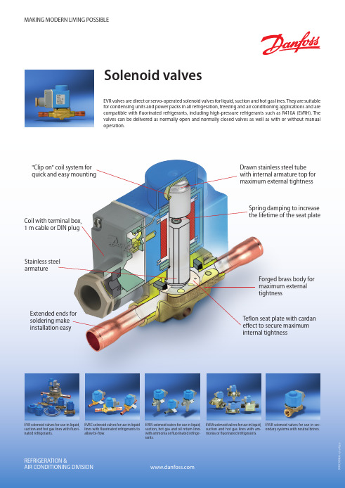
EVRA solenoid valves for use in liquid, EVSR solenoid valves for use in secsuction and hot gas lines with am- ondary systems with neutral brines. monia or fluorinated refrigerants.
EVRC solenoid valves for use in liquid lines with fluorinated refrigerants to allow bi-flow.
EVRS solenoid valves for use in liquid, suction, hot gas and oil return lines with ammonia or fluorinated refrigerants.
MAKING MODERN LIVING POSSIBLE
Solenoid valves
EVR valves are direct or servo-operated solenoid valves for liquid, suction and hot gas lines. They are suitable for condensing units and power packs in all refrigeration, freezing and air conditioning applications and are compatible with fluorinated refrigerants, including high-pressure refrigerants such as R410A (EVRH). The valves can be delivered as normally open and normally closed valves as well as with or without manual operation.
3个丹佛斯压力开关并在一起工作原理
3个丹佛斯压力开关并在一起工作原理
丹佛斯压力开关是一种常用的控制装置,可用于监测和调节液体或气体系统中
的压力。
在某些应用中,需要将多个丹佛斯压力开关连接在一起并实现协同工作。
以下是三个丹佛斯压力开关并在一起工作的基本原理:
1. 连接方式:首先,需要将三个丹佛斯压力开关正确连接在一起。
通常,每个
丹佛斯压力开关都有三个引脚,分别为正极(+)、负极(-)和输出信号(OUT)。
将它们按照正确的方式连接在一起,并确保它们的工作电压一致。
2. 差压控制:在某些应用中,需要同时监测和调节液体或气体系统中的差压。
通过将三个丹佛斯压力开关连接在一起,可以实现差压控制。
具体方法是将两个丹佛斯压力开关安装在流体系统的两个不同位置,使它们能够感知到系统的不同压力。
然后,根据差压情况,通过控制第三个丹佛斯压力开关的输出信号来调节系统的工作状态。
3. 串联控制:在某些应用中,需要同时监测和调节液体或气体系统的多个压力点。
通过将三个丹佛斯压力开关串联连接在一起,可以实现串联控制。
具体方法是将一个丹佛斯压力开关的输出信号连接到下一个丹佛斯压力开关的输入端。
这样,当第一个开关感知到压力变化并触发时,它会通过输出信号将信号传递给下一个开关,从而实现多个压力点的监测和调节。
总结起来,将三个丹佛斯压力开关并在一起工作的基本原理包括连接方式、差
压控制和串联控制。
通过合理安装和连接这些开关,可以实现复杂的压力监测和调节任务。
vickers比例阀技术参数
vickers比例阀技术参数摘要:I.简介- 简述Vickers比例阀II.技术参数- 工作压力- 控制流量- 调节范围- 响应时间- 温度范围III.应用领域- 液压传动系统- 工业自动化- 工程机械- 汽车制造IV.结论- 总结Vickers比例阀技术参数正文:I.简介Vickers比例阀是一种常用的流量控制阀门,具有结构简单、操作方便、控制精度高等特点。
它主要用于控制流体的流量和压力,以满足各种工业领域的需求。
II.技术参数1.工作压力Vickers比例阀的工作压力范围较广,一般可达100至700 bar。
这使得它能够适应各种高压、高流量的工况。
2.控制流量Vickers比例阀的控制流量能力较强,流量调节范围可达到100:1,甚至更高。
这使得它能够满足不同工况下的流量控制需求。
3.调节范围Vickers比例阀的调节范围较广,一般可达0.2至100%。
这使得它能够实现精确的控制,以满足各种工况的要求。
4.响应时间Vickers比例阀的响应时间较快,一般不超过100毫秒。
这使得它能够迅速响应工况变化,提高系统的稳定性和可靠性。
5.温度范围Vickers比例阀的温度范围较广,一般可达-40至120摄氏度。
这使得它能够适应各种温度的工况,具有较强的环境适应性。
III.应用领域1.液压传动系统Vickers比例阀广泛应用于各类液压传动系统中,如工程机械、汽车制造等领域,用于控制流量、压力等参数,提高系统的性能。
2.工业自动化在工业自动化领域,Vickers比例阀可用于控制各种流体介质,如液压油、气压等,实现自动化生产过程中的流量、压力控制。
3.工程机械在工程机械领域,Vickers比例阀可用于控制液压系统,如挖掘机、装载机等,提高机械设备的操作性能和稳定性。
4.汽车制造在汽车制造领域,Vickers比例阀可用于控制刹车系统、转向系统等,提高汽车的安全性和驾驶性能。
IV.结论综上所述,Vickers比例阀具有优良的技术参数和广泛的应用领域。
丹佛斯分集水器参数
丹佛斯分集水器参数一、引言丹佛斯分集水器是一种广泛应用于工业和环保领域的设备,它能够将固体颗粒从液体中分离出来,达到净化液体的目的。
本文将详细介绍丹佛斯分集水器的参数和应用。
二、丹佛斯分集水器参数1. 处理能力丹佛斯分集水器的处理能力是指单位时间内该设备处理的液体流量,通常以立方米/小时(m³/h)或加仑/分钟(GPM)为单位。
2. 分离效率分离效率是指丹佛斯分集水器分离固体颗粒的能力,通常以百分比表示,可以根据用户需求调整。
3. 进出口直径丹佛斯分集水器的进出口直径决定了它的液体进出口通道的尺寸,通常以毫米(mm)或英寸(inch)为单位。
4. 分离桶容积分离桶容积是指丹佛斯分集水器内部用于分离固液的空间大小,通常以升(L)或立方英尺(ft³)为单位。
分离桶容积越大,处理能力越强。
5. 进出口压力进出口压力是指丹佛斯分集水器的液体进出口处的压力要求,通常以巴(bar)或磅力/平方英寸(psi)为单位。
6. 电机功率丹佛斯分集水器需要驱动电机来运行,电机功率决定了设备的运行效率和能耗大小,通常以千瓦(kW)或马力(HP)为单位。
7. 设备尺寸设备尺寸是指丹佛斯分集水器的整体尺寸,包括长度、宽度、高度等,通常以毫米(mm)或英寸(inch)为单位。
三、丹佛斯分集水器应用1. 工业废水处理丹佛斯分集水器可以应用于工业废水处理过程中,有效地分离和去除废水中的固体颗粒,提高废水的处理效果。
2. 石油钻井液处理在石油钻井过程中,钻井液中含有大量的固体颗粒,丹佛斯分集水器可以帮助分离固体颗粒,净化钻井液,保证钻井作业的顺利进行。
3. 食品加工行业在食品加工过程中,有些流体需要去除固体颗粒,丹佛斯分集水器可以帮助实现这一目的,提高食品加工质量。
4. 污水处理在城市污水处理厂中,丹佛斯分集水器可以减少污水中的固体颗粒浓度,净化污水,降低对环境的影响。
5. 化工行业在化工生产中,一些液体需要经过分离过程,丹佛斯分集水器可以帮助去除固体颗粒,提高生产效率。
丹佛斯比例阀
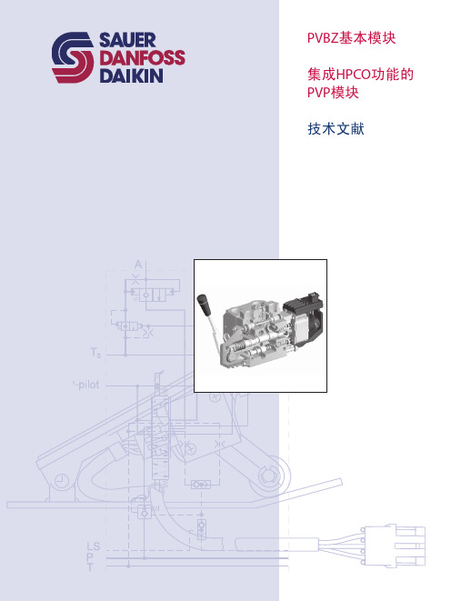
PVBZ基本模块技术文献版本修订历史目录概述 (3)剖视图 (4)功能 (5)技术参数 (6)PVP,泵侧模块-带T0口 (7)PVBZ,工作模块-带T0口 (8)PVB,工作模块-带T0口 (8)PVBZ,标准阀芯 (9)标准 FC- PVBZ阀芯 (电气和机械驱动) (10)标准 PVBZ悬浮阀芯 (电子驱动) (10)PVEH-F电气驱动 (10)PVST, 后端盖 (10)液压原理图 (11)驱动元件 (12)尺寸 (13)订购说明 PVBZ (14)订购说明 HPCO (15)© 2010 Sauer-Danfoss. 版权所有。
萨澳-丹佛斯对目录,说明书和其它出版物中可能存在的错误不负任何责任。
萨澳-丹佛斯有权不预先通知就更改其产品。
这同时也适用于已订购产品,尽管此类更改随后没有任何已认同的说明书中认为是必要的变化。
此资料中的所有商标都归属各自公司。
Sauer-Danfoss和Sauer-Danfoss标志为萨澳-丹佛斯集团商标。
2L1010371 • Rev CA • Jan 2010PVBZ基本模块技术文献PVBZ集成HPCO的PVP PVBZ模块是带有集成液控单向阀的工作模块。
PVBZ模块是为将集成了液控单向阀工作油口的泄露降到最低(低于1 cm3 [0.06 in3]每分钟)的应用而研发的。
PVBZ模块只能与本技术文献中提到的PVB工作模块和PVP泵侧模块结合使用,具有以下特征:• 集成低内泄液控单向阀• 集成热力安全阀• 标准 4/3(三位四通)阀芯• 4/4(四位四通)浮动阀芯• 阀芯可互换PVBZ(带独立回油口T0的PVB)模块是集成HPCO功能的PVG 32。
HPCO功能引导PVG 32阀组中多余的泵流通过HPCO口流到其它地方,如换向阀。
集成HPCO功能的新的PVP泵侧模块只能与本技术文献中提到的PVB、PVBZ和PVST模块配合使用,它具有以下特征:• HPCO功能• 优先保证PVG 32需要的流量• 节省油管概述3 L1010371 • Rev CA • Jan 2010PVBZ基本模块技术文献剖视图剖视图1 溢流阀2 先导油路减压阀3 压力表连接口4 堵头,开芯5 节流口,闭芯6 压力调节阀芯7 堵头,闭芯8 LS 连接口9 T0 连接口10 堵头 - 若T0内置,则移除 (仅157B5130,157B5131, 157B5330 和157B5331 )11 LS 信号12 POC先导阀13 梭阀14 液控单向阀, POC15 主阀芯16 压力补偿器17 梭针18 A和B口的最大油量调节螺钉19 PVE的先导油源20 独立回油口(T0)V310138.A4L1010371 • Rev CA • Jan 2010PVBZ基本模块技术文献功能功能当主阀芯(15)处于中位时,液控单向阀(POC)在弹簧力和工作压力的共同作用下保持关闭,工作压力经过阻尼孔作用于POC(14)的弹簧侧。
- 1、下载文档前请自行甄别文档内容的完整性,平台不提供额外的编辑、内容补充、找答案等附加服务。
- 2、"仅部分预览"的文档,不可在线预览部分如存在完整性等问题,可反馈申请退款(可完整预览的文档不适用该条件!)。
- 3、如文档侵犯您的权益,请联系客服反馈,我们会尽快为您处理(人工客服工作时间:9:00-18:30)。
PVBZ基本模块技术文献版本修订历史目录概述 (3)剖视图 (4)功能 (5)技术参数 (6)PVP,泵侧模块-带T0口 (7)PVBZ,工作模块-带T0口 (8)PVB,工作模块-带T0口 (8)PVBZ,标准阀芯 (9)标准 FC- PVBZ阀芯 (电气和机械驱动) (10)标准 PVBZ悬浮阀芯 (电子驱动) (10)PVEH-F电气驱动 (10)PVST, 后端盖 (10)液压原理图 (11)驱动元件 (12)尺寸 (13)订购说明 PVBZ (14)订购说明 HPCO (15)© 2010 Sauer-Danfoss. 版权所有。
萨澳-丹佛斯对目录,说明书和其它出版物中可能存在的错误不负任何责任。
萨澳-丹佛斯有权不预先通知就更改其产品。
这同时也适用于已订购产品,尽管此类更改随后没有任何已认同的说明书中认为是必要的变化。
此资料中的所有商标都归属各自公司。
Sauer-Danfoss和Sauer-Danfoss标志为萨澳-丹佛斯集团商标。
2L1010371 • Rev CA • Jan 2010PVBZ基本模块技术文献PVBZ集成HPCO的PVP PVBZ模块是带有集成液控单向阀的工作模块。
PVBZ模块是为将集成了液控单向阀工作油口的泄露降到最低(低于1 cm3 [0.06 in3]每分钟)的应用而研发的。
PVBZ模块只能与本技术文献中提到的PVB工作模块和PVP泵侧模块结合使用,具有以下特征:• 集成低内泄液控单向阀• 集成热力安全阀• 标准 4/3(三位四通)阀芯• 4/4(四位四通)浮动阀芯• 阀芯可互换PVBZ(带独立回油口T0的PVB)模块是集成HPCO功能的PVG 32。
HPCO功能引导PVG 32阀组中多余的泵流通过HPCO口流到其它地方,如换向阀。
集成HPCO功能的新的PVP泵侧模块只能与本技术文献中提到的PVB、PVBZ和PVST模块配合使用,它具有以下特征:• HPCO功能• 优先保证PVG 32需要的流量• 节省油管概述3 L1010371 • Rev CA • Jan 2010PVBZ基本模块技术文献剖视图剖视图1 溢流阀2 先导油路减压阀3 压力表连接口4 堵头,开芯5 节流口,闭芯6 压力调节阀芯7 堵头,闭芯8 LS 连接口9 T0 连接口10 堵头 - 若T0内置,则移除 (仅157B5130,157B5131, 157B5330 和157B5331 )11 LS 信号12 POC先导阀13 梭阀14 液控单向阀, POC15 主阀芯16 压力补偿器17 梭针18 A和B口的最大油量调节螺钉19 PVE的先导油源20 独立回油口(T0)V310138.A4L1010371 • Rev CA • Jan 2010PVBZ基本模块技术文献功能功能当主阀芯(15)处于中位时,液控单向阀(POC)在弹簧力和工作压力的共同作用下保持关闭,工作压力经过阻尼孔作用于POC(14)的弹簧侧。
当主阀芯被驱动,B口有油流出时,液压油强行打开B口的POC阀。
同时,先导油通过主阀芯到A油口侧的先导阀(12)的背面。
这保证了POC阀背面的负载压力通过座阀的独立T0口(20)释放到油箱中,从而使POC阀打开,让执行机构的回油通过主阀芯回到油箱。
对于浮动功能,两个POC阀背面的压力同时都被释放掉,POC阀打开,A和B口与油箱接通。
在某些配合3/3主阀芯和低负载压力(如提升应用)的应用中,必须通过梭针(17)强行打开POC阀。
梭针通过A侧的泵压驱动。
注意:PVM在B侧时,PVBZ模块不可选。
独立回油口T0消除了主回油路背压对POC阀的影响,从而确保了POC阀的正确功能。
因此,必须采用独立的油管,把进油联PVP的T0口(9)直接接回油箱。
集成式热力安全阀(157B6261, 157B6262, 157B6266 157B6661, 157B6662 和 157B6666)可以确保POC阀和油缸/马达间不会因为外界的热源而产生有害的高压。
热力安全阀的压力设定在276 bar [4003 psi], 最大流量为 1 l/min [0.264 US gal/min]。
注意:如果未使用独立回油口T0,那么必须移除堵头(10)。
由于157B5132, 157B5133,157B5332和157B5333没有堵头10,因此157B5132, 157B5133, 157B5332和157B5333中的T0口(9)必需接回油箱。
PVBZ只能与技术文献中提到的PVB和PVP联合使用。
当PVB,PVBZ,和带独立回油口的PVP(仅157B5140, 157B5142, 157B5340 和 157B5342)组合使用时,可能会导致带HPCO功能的PVP模块的回油背压增大。
来自PVG32 A和B口的回油必须通过PVST (157B2500和157B2520)盖板的独立回油口回油箱。
PVP 157B5140, 157B5142, 157B5340和157B5342处的T0油口必须始终连接到油箱。
参见11页的液压原理图和15页的相关规格。
5L1010371 • Rev CA • Jan 2010PVBZ基本模块技术文献最大压力P口 连续210 bar[3045 psi] A/B口210 bar[3045 psi] T口 静态/动态25 bar/40 bar[365/580 psi]额定流量P口140 l/min[37 US gal/min] A/B口,带压力补偿器100 l/min[26.4 US gal/min] A/B口,不带压力补偿器125 l/min[33 US gal/min]阀芯行程,标准± 7 mm[±0.28 in]阀芯行程,浮动阀芯比例范围± 5.5 mm[±0.22 in]浮动位置7.5 mm[±0.30 in]死区,流量控制阀芯标准阀芯± 0.8 mm[±0.03 in]最大内部泄露200 bar [2900 psi]21 mm2/s [102 SUS]A/B → T 1 cm3/min[0.06 in3/min]油温(入口油温)推荐温度30 → 60°C[86 → 140°F]最低温度-30°C[–22°F]最高温度+90°C[194°F]环境温度-30 → +60°C[–22 → +140°F]粘度工作范围12 - 75 mm2/s[65 - 347 SUS]最小粘度 4 mm2/s[39 SUS]最大粘度460 mm2/s[2128 SUS]过滤最大污染度(ISO 4406)18/16/1318/16/13技术参数技术参数6L1010371 • Rev CA • Jan 2010PVBZ基本模块技术文献模块和代码PVP, 泵侧模块416PVPX 卸荷阀, 见类别 DKMH.PK.570.C3.027L1010371 • Rev CA • Jan 2010PVBZ基本模块技术文献模块和代码PVBZ,工作模块连接: A 和 B口 G 1/2 [ 7/8 in - 14]PVBZ的密封件 157B69898L1010371 • Rev CA • Jan 2010PVBZ基本模块技术文献模块和代码PVB,工作模块连接: A 口和 B 口 G 1/2 [ 7/8 in - 14]9L1010371 • Rev CA • Jan 2010PVBZ基本模块技术文献PVBZ标准阀芯端盖板PVSTPVBZ标准FC-阀芯 (电气驱动和机械驱动) PVBZ标准浮动阀芯(电气驱动)PVEH-F电气驱动浮动阀芯与PVBZ 工作模块联合使用,仅限于 157B6266 和 157B6666 。
PVB浮动阀芯, 见DKMH.PK.570.C3.02目录标准电驱动器,见DKMH.PK.570.A2.02目录10L1010371 • Rev CA • Jan 201011L1010371 • Rev CA • Jan 2010PVBZ 基本模块技术文献液压原理图PVG32阀组带内置HPCO功能PVG32阀组带12L1010371 • Rev CA • Jan 2010PVBZ 基本模块技术文献驱动, PVEH - F驱动控制范围13L1010371 • Rev CA • Jan 2010PVBZ 基本模块技术文献尺寸尺寸V310127.A1油口连接: T0, M, PP , LS G1/4 [1/2 in - 20]14L1010371 • Rev CA • Jan 2010PVBZ 基本模块技术文献带有PVBZ 阀组PVG 32规格举例991L1865 ver. 03.2002子公司/经销商PVG 型号客户客户号应用版本号功能A-口O 157B 5133 157B 4236 p = 210bar157BB-口a 157B 3171b 157B 1 157B 6010157B 7003 13 LS A bar LS Bbar157B 4228 c 157Bba 157B 3171b 157B 22402 157B 6240 157B 7004 13 LS A bar LS Bbar157B 4734 c 157B 2240 b a 157B 3191b 157B 3 157B 6051 157B 9403 13 LS A bar LS Bbar157B 4034 c 157B b a 157B 3191b 157B 4 157B 6266 157B 9415 13 LS A bar LS Bbar157B 4338 c 157Bba 157Bb 157B 5 157B 157B 13 LS A bar LS Bbar157B c 157B b a 157B b 157B 6 157B 157B 13 LS A bar LS Bbar157B c 157B b a 157B b 157B 7 157B157B 13 LS A bar LS Bbar157B c 157B b a 157B b 157B 8 157B 157B 13 LS A bar LS Bbar 157Bc 157Bb a 157B b 157B 9 157B 157B 13 LS A bar LS Bbar157B c 157B b a 157B b 157B10 157B 157B 13 LS A bar LS Bbar157B c 157Bb备注11 157B200012 157B8004填写者日期15L1010371 • Rev CA • Jan 2010PVBZ 基本模块技术文献带有HPCO 的PVBZ 阀组PVG 32规格举例991L1865 ver. 03.2002子公司/经销商PVG 型号客户客户号应用版本号功能A-口O 157B 5142 157B4236 p = 210bar157BB-口a 157B 3171b 157B 1 157B 6010157B 7001 13 LS A bar LS Bbar157B 4901 c 157Bba 157B 3171b 157B 2 157B 6110 157B 7002 13 LS A bar LS Bbar157B 4734 c 157B b a 157B 3193b 157B 3 157B 6210 157B 7003 13 LS A bar LS Bbar157B 4034 c 157B b a 157B 3193b 157B 4 157B 6213 157B 7024 13 LS A 50 bar LS B 150bar157B 4834 c 157Bba 157Bb 157B 5 157B 157B 13 LS A bar LS Bbar157B c 157B b a 157B b 157B 6 157B 157B 13 LS A bar LS Bbar157B c 157B b a 157B b 157B 7 157B157B 13 LS A bar LS Bbar157B c 157B b a 157B b 157B 8 157B 157B 13 LS A bar LS Bbar 157Bc 157Bb a 157B b 157B 9 157B 157B 13 LS A bar LS Bbar157B c 157B b a 157B b 157B10 157B 157B 13 LS A bar LS Bbar157B c 157Bb备注11 157B250012 157B8004填写者日期L1010371 • Rev CA • Jan 2010产品系列静液压传动系统液压动力转向装置电动力转向装置电液动力转向装置闭式及开式回路轴向柱塞泵及马达齿轮泵及马达弯轴变量马达摆线马达混凝土搅拌车系统比例阀风扇驱动系统电液控制系统微控制器及软件电控操作杆和控制手柄显示器传感器。