丹佛斯电动调节阀
丹佛斯电动调节阀

丹佛斯电动调节阀1. 简介丹佛斯电动调节阀是一种用于控制流体介质的设备,采用电动执行机构作为驱动力源,以实现精确的流量调节和流体控制。
该调节阀具有调节精度高、响应速度快、可远程操作等特点,广泛应用于各行各业的工业自动化控制系统中。
2. 结构与原理2.1 结构丹佛斯电动调节阀的主要组成部分包括阀体、阀座、活塞、电动执行机构等。
•阀体:通常采用优质铸铁或不锈钢材料制成,具有良好的耐腐蚀性和密封性能。
•阀座:位于阀体内部,通过调节阀座的开度来控制流体的流量。
•活塞:负责连接阀芯和电动执行器,调节阀芯的位置和开度。
•电动执行机构:由电机和传动装置组成,通过控制电机的正反转来实现阀芯的升降,从而调节阀的开度。
2.2 原理丹佛斯电动调节阀的工作原理基于反馈控制系统。
当控制系统发送控制信号时,电动执行机构根据信号的输入来调节阀芯的位置,从而改变阀座的开度,进而调节流体的流量。
同时,通过传感器获取流体的参数,并将反馈信号发送给控制系统进行实时监测和调整,以保证流体的稳定控制。
3. 特点与优势3.1 调节精度高丹佛斯电动调节阀采用先进的控制算法和精密的执行机构,具有极高的调节精度,能够实现精确到百分之一的流量控制。
3.2 响应速度快电动执行机构具有快速响应的特点,能够在短时间内完成阀芯的升降,实现快速调节和控制。
3.3 远程操作与监控丹佛斯电动调节阀支持远程操作与监控,通过与控制系统的连接,实现远程控制和参数监测,提高了操作的便捷性和效率。
3.4 可编程性强该电动调节阀具备良好的可编程性,用户可以根据实际需求自定义控制策略和参数,以适应不同的工业流程要求。
3.5 耐腐蚀性好丹佛斯电动调节阀采用优质的阀体材料,具有良好的耐腐蚀性,可以适应多种流体介质的控制需求。
4. 应用领域丹佛斯电动调节阀广泛应用于以下领域:•石油化工:用于炼油、化工生产中的流体控制和调节。
•电力行业:用于电厂锅炉的水位控制和调节。
•冶金行业:用于冶金过程中炉温的控制和调节。
丹佛斯Danfoss静态平衡阀MSV-F2参数表-水力平衡

参数表静态平衡阀MSV-F2, PN 16/25, DN 15 - 400描述MSV-F2 为静态平衡阀。
它用在供热和制冷定流量水系统中平衡流量。
这种阀门标配阀位指示和行程限制。
阀杆罩与行程限制集成为一体。
阀门设定值可被锁定。
在测量仪器PFM3000/4000中建有该阀门流量特性数据。
阀门不含石棉。
具有关断功能主要数据:• DN 15- 400• PN 16: - 水流温度: –10 °C … 130 °C • PN 25:- 水流温度: –10 °C … 150 °C• 阀门可安装与供水管或回水管上。
MSV-F2 DN 15-150应用MSV-F2 DN 200-400在定流量系统中,MSV 阀门可保持恒定的压降。
根据预设定值,阀门可设定多种压降。
订货附件型号产品编号Rectus型快速测量接头003Z0108针式测量接头,2 件003Z0104加长型针式测量接头45 mm,2 件003Z0103针式测量接头连接件,2 件003Z0107 PFM4000测量仪器参见相关参数表型号产品编号手轮DN 15- 50003Z0179DN 65- 150003Z0180DN 200003Z0181DN 250- 300003Z0182DN 350- 400003Z0183MSV-F2 阀门 - PN 16公称直径DN 1520253240506580100125150200250300350400k vs (m 3/h ) 3.16.39.015.532.353.893.4122.3200.0304.4400.8685.6952.31380.22046.12584.6公称压力(Bar)16最大压降(Bar)1.5泄漏率 A 级:依照 ISO5208,表 5(无可见渗漏)流体介质水以及水与辅助冷却剂(如乙二醇)的混合物* ,用于闭式供暖和制冷系统流体最高温度(°C) 130连接符合 EN 1092-2 标准的法兰重量(闭式) 2.32.93.85.67.29.41721324356231354497747890阀体材料铸铁 EN-GJL 250 (GG 25)阀座密封EPDM圆锥材料CW602NCuSn5Zn5Pb5铸造不锈钢* 请向供应商确认材料与辅助冷却剂的相容性。
丹佛斯变量容积泵系列20、20-27系列零件手册说明书
MAKING MODERN LIVING POSSIBLEQuick Reference Parts ManualVariable Displacement Pump Series 20, 20-27 seriesAX00000099 en-US | 520L0910 • Rev 0203 • August23AX00000099 en-US | 520L0910• Rev 0203 • August Contents Exploded view drawing (20 thru 23 series) (4)Service parts (20 thru 23 series) (5)Exploded view drawing (24 thru 27 series) (6)Service parts (24 thru 27 series) (7)SPV2/033 (20 series) (8)SPV2/052 (21 series) (8)SPV2/070 (22 series) (8)SPV2/089 (23 series) (8)SPV2/119 (24 series) (9)SPV2/166 (25 series) (9)SPV2/227 (26 series) (9)SPV2/334 (27 series) (9)Service parts Drive shafts4AX00000099 en-US | 520L0910 • Rev 0203 • August5AX00000099 en-US | 520L0910• Rev 0203 • August Item # Discription SPV2/033 (20) SPV2/052 (21) SPV2/070 (22) SPV2/089 (23) Overhaul seal kit 9510224 9510227 9510230 9510233 1 Shaft seal kit 050088 050088 050088 0503022 O-ring 056788 (9004104-2340) 056788 (9004104-2340) 056788 (9004104-2340) 071860 (9004104-2380)3 O-ring 008821 (9004104-1290) 008821 (9004104-1290) 008821 (9004104-1290) 008979 (9004104-1360)4 Seal kit 9510022 9510022 9510022 95100215 Front bearing kit 050575 (9510251) 050575 (9510251) 050625 (9510256) 050658 (9510259)6 Swashplate, 18° 002725 9210279 9220570 95107617 Cylinder block kit 510149 593251 596890 92309738 Piston kit, set of 3 711291 (not a kit of 3) 9510408-0010 9510408-0001 9510408-0002 8 Remanufactured 711291 R9510408-0010 R9510408-0001 R9510408-00029 Slipper retainer 9200158 003210 (9210292) 003707 (9220628) 004176 (9230234) 10 Slipper ret. guide J9200124 003160 (9210219) 9220500 9230158 11 Pilot ring 002709 010678 013862 00432512 Bearing plate 002733 585885 585893 56167013 Valve plate, cw 002881 003368 003889 004333Valve plate, ccw 002899 003376 003897 00434114 Rear bearing kit 050567 (9510250) 050591 (9510253) 050617 (9510255) 050641 (9510258) 15 End cap gasket 9200088 9210204 9220425 9231081 16 Chg pump gasket, gear 9801235 9801235 9801235 9801235 gerotor with IPOR n/a 9803241* 9803241* 9803241* gerotor without IPOR n/a 9803252* 9803252* 9803252*17 O-ring 000869 (9004100-1390) 000869 (9004100-1390) 512007 (9004100-1430) 512007 (9004100-1430) 18 O-ring 000851 (9004100-1360) 000851 (9004100-1360) 512008 (9004100-1410) 512008 (9004100-1410) 19 Thrust plate 010520 003228 (9210293) 003699 (9220626) 00418420 Trunnion bearing kit 050583 (9510252) 050609 (9510254) 050633 (9510257) 050666 (9510639) prior to 88-01-xxxxx 951026021 O-ring 000927 (9004100-2260) 000935 (9004100-2280) 000943 (9004100-2300) 000950 (9004100-2320) 22 Trunnion shim kit 9510422-0001 9510422-0002 9510422-0003 9510422-0004 23 Servo piston link 589317 589317 589325 59467187-13 thru 97-23 n/a 9210620 9221367 9230787 24 Retaining ring 9006300-0050 9006300-0050 9006300-0062 9006300-006225 Pin 013904 (9004830-0001) 013904 (9004830-0001) 013680 (9004830-0002) 013680 (9004830-0002) 26 Check valve assembly 075366 (9800648) 075366 (9800648) 075366 (9800648) 075366 (9800648) 27 O-ring 056770 (9004101-0150) 056770 (9004101-0150) 056770 (9004101-0150) 056770 (9004101-0150) 28 Servo sleeve assembly 9200582 9200582 9510207 9510207 29 Servo sleeve assembly 9200583 9200583 9510350 9510350 30 Stroke limiter kit 9200515 9200515 9221078 9221078 31 Torx screw 9007276-0011 9007276-0011 9007276-0011 9007276-0011 32 Servo retainer 9200087 9200087 9220419 9220419 33 Control gasket 9803340 9803340 9803340 980334034 O-ring 001032 (9004101-0140) 001032 (9004101-0140) 001032 (9004101-0140) 001032 (9004101-0140) 35 Front cover gasket 9200076 9210201 9221528 9230124 36 Cylinder block 049155 049163 014878 01491036 Remanufactured n/a R9210576 R9221102 R9230651 37 Cylinder block assy n/a n/a 11077853 520087/P * Indicated special charge pump gaskets (item # 16) are not included in the overhaul seal kit.Service parts6AX00000099 en-US | 520L0910 • Rev 0203 • August7AX00000099 en-US | 520L0910• Rev 0203 • August Service parts Item # Discription SPV2/119 (24) SPV2/166 (25) SPV2/227 (26) SPV2/334 (27) Overhaul seal kit 9510236 9510239 9510316 9510242 1 Shaft seal kit 050302 050302 058537 0505342 O-ring 000984 (9004100-2380) 000984 (9004100-2380) 049718 (9004100-2420) 000992 (9004100-2430)3 O-ring 008979 (9004104-1360) 008979 (9004104-1360) 680892 (9004104-1440) 012187 (9004104-1490)4 Seal kit 9510021 9510021 n/a n/a5 Front bearing kit 050658 (9510259) 9510264 9510267 050732 (9510270)6 Swshplate, 18° 9240197 9250164 9260152 9270462 7 Cylinder block kit 9240641 634923 9260369 9270658 8 Piston kit, set of 3 9510408-0004 9510408-0005 9510408-0006 9510408-0009 8 Remanufactured R9510408-0004 R9510408-0005 R9510408-0006 R9510408-0009 9 Slipper retainer 9240125 9250170 9260072 9270486 10 Slipper ret. guide 9240097 005090 046243 00558711 Pilot ring 702381 634907 634915 63489912 Bearing plate 9240560 585901 9260321 58592713 Valve plate, cw 004895 651810 9260355 62232413 Valve plate, ccw 004903 628933 9260356 65196814 Rear bearing kit 050674 (9510261) 050690 (9510263) 055434 (9510266) 050724 (9510386) 15 End cap gasket 9240549 9250587 9260144 9270710 16 Chg pump gasket, gear 9801604 9801604 9801604 9801604 gerotor with IPOR 9803241* n/a n/a n/agerotor without IPOR 9803252* n/a n/a n/a17 O-ring 000901 (9004100-1510) 000901 (9004100-1510) 000919 (9004100-1560) 000919 (9004100-1560) 18 O-ring 000893 (9004100-1500) 000893 (9004100-1500) 000992 (9004100-2430) 000992 (9004100-2430) 19 Thrust plate 011015 (9240124) 005181 (9250171) 049635 (9260073) 004184 (9230235) 20 Trunnion bearing kit 050682 (9510262) 050609 (9510254) 050633 (9510257) 050666 (9510639) 21 O-ring 000968 (9004100-2340) (9004100-2280) (9004100-2300) 000950 (9004100-2320) 22 Trunnion shim kit 9510422-0005 9510422-0006 9510422-0007 9510422-0008 23 Servo piston link 9240584 9250617 9260252 9270653 24 Retaining ring 9006300-0075 9006300-0075 9006300-0087 9006300-008725 Pin 9004830-0008 9004830-0008 013680 (9004830-0002) 013680 (9004830-0002) 26 Check valve assembly 075366 (9800648) 543553 (9802028) 543553 (9802028) 543553 (9802028) 20 gpm 527887 n/a n/a n/a27 O-ring 056770 (9004101-0150) 063230 (9004101-0270) 063230 (9004101-0270) 063230 (9004101-0270) 20 gpm valve 012575 (9004105-1170) n/a n/a n/a28 Servo sleeve assembly 9510208 9510208 n/a n/a29 Servo sleeve assembly 9510351 9510351 9510331 9510331 30 Stroke limiter kit 9240326 9240326 9260185 9260185 31 Torx screw 9007276-0011 9007276-0011 9007276-0011 9007276-0011 32 Servo retainer 9240076 9240076 9270178 9270178 33 Control gasket 9803340 9803340 9803340 980334034 O-ring 001032 (9004101-0140) 001032 (9004101-0140) 001032 (9004101-0140) 001032 (9004101-0140) 35 Front cover gasket 9240070 9250158 9260145 9270175 17 Cylinder block 049171 073585 073619 07118317 Remanufactured R9240394 R9250470 R9260231 R9270495 * Indicated special charge pump gaskets (item # 16) are not included in the overhaul seal kit.8AX00000099 en-US | 520L0910 • Rev 0203 • AugustPart Number Description010827 14 tooth spline, gear charge pump707828 20 tooth spline, gear charge pump046557 21 tooth spline, M10 threaded hole, gear charge pump708073 Straight key, 3/8-24 UNF-2B threaded hole, gear charge pump 9003261-3132 Key, 5/16 x 5/16 x 2 1/2080465 14 tooth spline, gear charge pump9210663 14 tooth spline, gerotor charge pump018812 21 tooth spline, gear charge pump9210673 21 tooth spline, gerotor charge pump9210428 Tapered, gear charge pump9003310-3724 Key5000606 (9700169) Slotted nut9210538 Straight key, gear charge pump9003261-3132 Key, 5/16 x5/16 x 2 1/2144402 14 tooth spline, gear charge pump9221447 14 tooth spline, gerotor charge pump079913 (9220515) 19 tooth spline, gear charge pump9220527 20 tooth spline, 3/8-24 UNF-2B threaded hole, gear charge pump 9221475 20 tooth spline, 3/8-24 UNF-2B threaded hole, gerotor charge pump 048504 (9220417) 21 tooth spline, gear charge pump9221441 21 tooth spline, gerotor charge pump046581 (9220884) Tapered, gear charge pump9003310-3724 Key5000606 (9700169) Slotted nut039644 (9221065) Straight key, 3/8-24 UNF-2B threaded hole, gear charge pump 9003261-3132 Key, 5/16 x5/16 x 2 1/29230476 14 tooth spline, gear charge pump9230951 14 tooth spline, gerotor charge pump014985 (9230325) 21 tooth spline, gear charge pump9230968 21 tooth spline, gerotor charge pump9230173 23 tooth spline, 3/8-24 UNF-2B threaded hole, gear charge pump 9231014 23 tooth spline, 3/8-24 UNF-2B threaded hole, gerotor charge pump 9230147 27 tooth spline, 3/8-24 UNF-2B threaded hole, gear charge pump 9230445 Tapered, 1.5” nominal shaft dia., gear charge pump9003310-3724 Key5000606 (9700169) Slotted nut9230989 Tapered, 1.375” nominal shaft dia., gerotor charge pump 9003310-3724 Key5000606 (9700169) Slotted nut9230626 Straight key, 3/8-24 UNF-2B threaded hole, gear charge pump 9003261-3132 Key, 3/8 x 3/8 x 2 1/2SPV2/033 (20 series)SPV2/052 (21 series)SPV2/089 (23 series)SPV2/070 (22 series)9AX00000099 en-US | 520L0910• Rev 0203 • August Drive shaft Part Number Description 07930113 tooth spline, M14 x 2-6H tapped hole, gear charge pump 924068513 tooth spline, gerotor charge pump 04684727 tooth spline, M14 x 2-6H tapped hole, gear charge pump 9240231Tapered, gear charge pump 9003326-0005Key 9700189Slotted nut 9240713Tapered, gerotor charge pump 9003326-0005Key 9700189Slotted nut 039982Straight key, 1/2-20 UNF-2B threaded hole, gear charge pump 9003261-3732Key, 3/8 x 3/8 x 2 1/2054940 13 tooth spline, gear charge pump047894 27 tooth spline with M14 x 2-6H tapped hole, gear charge pump9250409 Straight key, 1/2-20 UNF-2B threaded hole, gear charge pump9003261-3732 Key, 3/8 x 3/8 x 2 1/29260140 13 tooth spline, gear charge pump045930 27 tooth spline, M14 x 2-6H tapped hole, gear charge pump9260176 Straight key, 1/2-20 UNF-2B threaded hole, gear charge pump9003261-5040 Key, 1/2 x 1/2 x 3 1/2077727 15 tooth spline, gear charge pump9270741 40 tooth spline, M16 tapped hole, gear charge pump561530 Straight key, 1/2-20 UNF-2B threaded hole, gear charge pump 9003261-6244 Key, 5/8 x 5/8 x 4SPV2/166 (25 series)SPV2/119 (24 series)SPV2/334 (27 series)SPV2/227 (26 series)AX00000099 en-US | 520L0910 • Rev 0203 • August1011AX00000099 en-US | 520L0910• Rev 0203 • August NotesDanfoss Power Solutions is a global manufacturer and supplier of high-quality hydraulic and electronic components. We specialize in providing state-of-the-art technology and solutions that excel in the harsh operating conditions of the mobile off-highway market. Building on our extensive applications expertise, we work closely with our customers to ensure exceptional performance for a broad range of off-highway vehicles. We help OEMs around the world speed up system development, reduce costs and bring vehicles to market faster. Danfoss – Your Strongest Partner in Mobile Hydraulics.Go to for further product information.Wherever off-highway vehicles are at work, so is Danfoss. We offer expert worldwide support for our customers, ensuring the best possible solutions for outstanding performance. And with an extensive network of Global Service Partners, we also provide comprehensive global service for all of our components. Please contact the Danfoss Power Solution representative nearest you.Products we offer:y Bent Axis Motorsy Closed Circuit Axial Piston Pumps and Motorsy Displaysy Electrohydraulic Power Steeringy Electrohydraulicsy Hydraulic Power Steeringy Integrated Systemsy Joysticks and Control Handlesy Microcontrollers and Softwarey Open Circuit Axial Piston Pumpsy Orbital Motorsy PLUS+1® GUIDEy Proportional Valvesy Sensorsy Steeringy Transit Mixer Drives Comatrol Schwarzmüller-Inverter www.schwarzmueller- Turolla Valmova Hydro-Gear Daikin-Sauer-Danfoss Local address:Danfoss can accept no responsibility for possible errors in catalogues, brochures and other printed material. Danfoss reserves the right to alter its products without notice. This also applies to products already on order provided that such alterations can be made without subsequential changes being necessary in specifications already agreed.All trademarks in this material are property of the respective companies. Danfoss and the Danfoss logotype are trademarks of Danfoss A/S. All rights reserved.Danfoss Power Solutions 22F, Block C, Yishan Rd Shanghai 200233, China Phone: +86 21 3418 5200Danfoss Power Solutions GmbH & Co. OHG Krokamp 35D-24539 Neumünster, Germany Phone: +49 4321 871 0Danfoss Power Solutions ApS Nordborgvej 81DK-6430 Nordborg, Denmark Phone: +45 7488 2222Danfoss Power Solutions US Company 2800 East 13th Street Ames, IA 50010, USA Phone: +1 515 239 6000AX00000099 en-US | 520L0910 • Rev 0203 • August © Danfoss A/S, 2015。
丹佛斯Danfoss截止阀技术手册
压力设备指令(PED) REG 过滤器符合压力设备指令中规定的欧洲标 准,并带有欧盟强制认证标识。
REG-SA 和 REG-SB 阀门 公称管径 分类目的 类别 第3条第3段 DN = < 25 毫米(1 英寸) DN32-80 毫米 (1¼ - 3 英寸) 液体组 I II III DN100 – 125 毫米(4 - 5 英寸)
R717
A B
0%
25%
50%
䕈ⱘ䕀ࡼ
100% ᠧᓔ
图6
गܟᇣᯊ
(⺙ߚ䩳) 8000 (294)
REG-SA 15-20 和 REG-SB 15-20
∆P = 2 bar (29 psi) ∆P = 1.5 bar (22 psi) ∆P = 1 bar (14 psi) ∆P = 0.5 bar (7 psi)
图2
4
REG-SA 15-20 和 REG-SB 15-20
B
A
2
3 25%
4
5 50%
6
7 75%
8
9 100%
䕈ⱘ䕀ࡼ ᠧᓔ
DKRCI.PD.KM1.A6.41 / 520H7320
© Danfoss A/S (MWA), 2015-01
REG-SA 型和 REG-SB 型手动调节阀 计算和选择(续) 流量系数
© Danfoss A/S (MWA), 2015-01
DKRCI.PD.KM1.A6.41 / 520H7320 3
REG-SA 型和 REG-SB 型手动调节阀 计算和选择 流量系数
Kv (Cv) 0.6 (0.70) 0.5 (0.58) 0.4 (0.46) 0.3 (0.35) 0.2 (0.23) 0.1 (0.12) 0
3 丹佛斯机组及主要部件介绍

Danfoss 换热机组及部件介绍丹佛斯区域能源技术部户用小型换热机组多户用小型换热机组大型换热机组中型换热机组Danfoss 机组产品全系列机组产品全系列、、多功能设计通常要考虑设计通常要考虑::机组本身热负荷参数等 机组整体结构 客户特殊需求,如布置空间、噪音等 机组所处热力系统的水力工况设计方案量体裁衣设计方案量体裁衣,,关注客户利益机组优化设计软件机组优化设计软件,,资深的专业技术人员三维三维设计设计设计,,结构紧凑结构紧凑,,优化布局优化布局,,维修方便优化的专业设计着重细节着重细节,,追求完美细微之处见真功细微之处见真功,,Danfoss 的设计细致到每个细节的设计细致到每个细节,,精益求精精益求精。
精心选择测点位置精心选择测点位置,,保证数据采集真实准确排气装置排污装置卸压装置完备的排气完备的排气、、排污及安全卸压装置排污及安全卸压装置,,保证机组稳定运行着重细节着重细节,,追求完美细微之处见真功细微之处见真功,,Danfoss 的设计细致到每个细节的设计细致到每个细节,,精益求精精益求精。
着重细节着重细节,,追求完美细微之处见真功细微之处见真功,,Danfoss 的设计细致到每个细节的设计细致到每个细节,,精益求精精益求精。
过滤器本体具有压差检测功能过滤器的精巧设计,使得压差检测功能变得简单容易恶劣水力工况下,采用压差控制装置确保机组的温度稳定调节。
机组配置80%以上是 以上是Danfoss产品 机组配置 以上是 产品Danfoss换热器Danfoss电动调节阀Danfoss ECL 控制器Danfoss温度/压力传感器Danfoss超声波热量表Danfoss球阀Danfoss变频器Grundfos水泵Danfoss板式换热器 板式换热器• 板片厚度:0.5mm • 沟槽深度:2.8~3.9mm • 板片材质:AISI304 AISI316 • 密封垫片:NBR(丁晴) EPDM(三元乙丙) • 接口尺寸:DN32~DN300 • 接口方式:螺纹连接 法兰连接Danfoss板式换热器 板式换热器方便安装的免粘接垫片 独特的定位系统一次冲压成形确 保板片精度独特的紧固螺栓设计 卓越的导流区设计Danfoss球阀 球阀• 免维护 • 阀体为整体焊接件,易打开和关闭 • 阀门关闭严密,操作轴密封严密 • 低阻力,减少水泵能耗操作轴处的密封严密 阀门关闭严密Danfoss电动调节阀 电动调节阀• 流通能力高 • 流量特性为等百分比特性,控制性能好 • 有自检阀门行程的功能, 减少调试时工作量 • 泄漏率低 • 易于安装和操作 • 可手动操作(电手动和机械手动) • 最大口径达到DN250,最高耐温可达350℃ • 可实现控制信号分割功能 • 故障自诊断功能Danfoss电动调节阀 电动调节阀驱动器功能(AME 10/20/30/15/25/35/55/85系列 系列) 驱动器功能 系列U 2V...---V Direct 0(2)V...5(6)V Proportional LOG. flow 100% Kvs Reset1 2 3 4 5 6 7 8 9---I 0V...---V Inverse Sequential 5(6)V...10V 3 point / RL LIN. flow Red. Kvs ResetDanfoss电动调节阀 电动调节阀I• 控制信号的选择 • 控制信号起点 • 正反向动作A A B A B A B AB1U1A BA BABBABABAAB B2 (0)10V4 (0)UI20mA0V...---V0V...---VInverse11112V...---V2V...---VDirectABABABABA BABA BABA BABA BABABABABABA BABAAB BA BABAAB B0 02 410 20V mA0 010 20V mA0 010 20V mA0 0DirectInverse10 20V mADanfoss电动调节阀 电动调节阀•控制信号分割功能当两个调节阀并联时Sequential 5(6)V...10V Sequential 5(6)V...10V1A B A B AB A B A AB B1---0(2)V...5(6)VABA BABABA BAB0 05 1010 20V mA0 05 100(2)V...5(6)V---10 20V mADanfoss电动调节阀 电动调节阀• 模拟量控制和三点控制合为一体 AMV,AME3 point / RL 3 point / RL6A B6ProportionalAB24VACA BABA BABABABProportional24VACA B AB A AB B0 010 20V mADanfoss电动调节阀 电动调节阀• 改变阀门特性功能线性、等百分比特性LIN. flow77A BLOG. flowABA BABA BABABABA BABAAB B0 010 20V mA0 0LOG. flowLIN. flow10 20V mADanfoss电动调节阀 电动调节阀• Kvs值限制功能DN125 Kvs=220 DN150 Kvs=320 计算Kv=270? 建议当所选调节阀的Kvs值大于计算Kv 值20%以上时应用此功能Red. Kvs81A B8100% KvsABA BABAAB B100% Kvs100% KvsRed. Kvs82% KvsABABA BABAAB B0 010 20V mA0 010 20V mADanfoss压差控制器 压差控制器压差控制器工作原理MDV压差控制器是在水系统中用来保持某两点间压 差恒定的自力式控制阀,一般由阀体,驱动膜盒, 导压管等部分组成. 其工作原理如左图所示(左图为压差控制器控 制电动调节阀两端的压差): 电动调节阀(MDV)上游的高压通过导压管引 导至控制膜盒下侧. 电动调节阀下游的压力通过外部导压管或内部 导压孔引导至控制膜盒上侧. 由压差引起的作用力与内部弹簧的作用力相互 平衡,使调节阀两端的压差保持恒定.压差控制器侧压高侧压中侧压低调节弹簧的预紧力,即可调节压差设定值.Danfoss压差控制器 压差控制器为什么使用差压控制器?• 保持电调阀两端压差恒定——保证调节阀的调节特性,使控温准确 ——减少调节阀动作次数,延长使用寿命 ——限制全开时最大流量,反之全开时近端热站 局部“抢水”(热权度小于1)• 保证电调阀在较低的压差下工作——防止电调阀两端压差超过其最大关闭压差 ——防止出现气穴现象,降低噪音Danfoss变频器 变频器FC100系列 变频器 系列• 专为水泵、风机的应用而设计制造 • 电压矢量控制模式 • 优化的谐波性能,内置双直流电抗器 • 最佳的EMC特性,内置射频干扰滤波器 • 自动能量优化功能 • 电机自适应功能 • 双通道PID调节 • 电机友好性 • 完全的自身及电机保护 • 水泵专用功能管网水力补偿功能/无流量检测功能/睡眠功能降低能源消耗 降低噪音 水泵与管道寿命长 水泄漏降至最低Danfoss ECL控制器 控制器专用于供热和暖通空调系统的控制器 – ECL200/300 1. 使用简单, 调试时只需设定即可, 勿需任何编程 2. 操作方便, 只需简单培训工人即可操作 3. 安装简便, 运行可靠性高 4. 性价比高功能强大的可编程控制器 – ECL Apex 20 1. 使用灵活, 扩展性强 2. 组网方便, 本地化的HMI界面Danfoss ECL控制器 控制器• 气候补偿 • 分时控温 • 一次网回水温度限制 • 优化控制 • 室内温度影响ECL 200/300•功能专一,使用方便简单 • 气候补偿供暖控制或生活热水恒温控制, 根据室外温度 调节供水温度,节能舒适. •分时供暖 •PI 控制,三点可控硅输出。
丹佛斯散热器恒温控制阀2

参数表RTD Inova TM型恒温阀传感器 E N 215 -1应用订货及参数RTD Inova TM3130RTD Inova TM3132RTD伊诺系列是散热器恒温阀的系列产品,适用于各种中央及独立的热水供暖系统。
RTD是气体填充的具有小型比例带的自力式比例调节型控制器。
可以保证室内温度恒定,提供一个高舒适性的环境,并可以有效地节能。
RTD伊诺系列恒温传感器包括:・ RTD Inova TM 3130:内置式传感 器并具有防冻功能,温度调节范围 6-26℃,可限制和锁定温度设定 值。
・ RTD Inova TM 3132:远程式传感 器并具有防冻功能,温度调节范围 6-26℃,可限制和锁定温度设定 值。
RTD伊诺系列恒温传感器都可与RTD系列恒温阀阀体进行组合。
传感器和阀体的连接使用既简单又坚固的镀镍结合螺帽。
防盗配件可防止私自拆卸传感器。
RTD阀体和RTD 伊诺恒温传感器连接的技术数据符合欧洲标准EN215-1。
RTD伊诺恒温传感器类型订货编号特性毛细管长度 温度范围2)RTD Inova TM 3130013L3130内置式传感器-6-26℃RTD Inova TM 3132013L3132远程式传感器0-2m1)6-26℃1)出厂时,远程式传感器的所有毛细管盘绕在传感器内,安装时只拉出所需长度的毛细管即可。
2)Xp=2K的描述是,当室温高出设定室温2℃时,阀门即关闭。
参数表RTD Inova TM型恒温阀传感器传感器选择原则内置式传感器远程式传感器传感器必须安装在能时刻正确感受室内环境温度的位置:・ 传感器不能被遮盖,如窗帘;・ 传感器不能受气流影响;・ 传感器应该水平安装。
如果竖直安装, 传感器将受到阀体和管道表面的散热 影响,导致错误动作。
・ 传感器温度调节部分应容易触及。
远程式传感器应用在内置式传感器无法正确感受环境温度的地方:・ 传感器不能被遮盖,如窗帘;・ 传感器不能受气流影响;・ 传感器应该水平安装;・ 传感器温度调节部分应容易触及。
丹佛斯-自动控制产品介绍

38
精选完整ppt课件
调节范围
39
精选完整ppt课件
ACB 插式压力控制器
40
精选完整ppt课件
ACB,即插式压力控制器
ACB 即插式压力控制器是一种小型圆盘式压力控 制器用于制冷和空调系统中。 ACB 型配有标准的 6 安培接触系统,可以自动 回复或手动回复. ACB强度高,可靠,紧凑,轻巧,防护等级高, 可以直接安装在制冷系统需要压力调节的地方.
另一种是组合式由导阀操纵的电磁阀(电磁主阀 PML)
30
精选完整ppt课件
PML电磁阀
31
精选完整ppt课件
32
精选完整ppt课件
VHV/STF 4通换向阀
33
精选完整ppt课件
34
精选完整ppt课件
电磁阀的选择:
1、它所适用的流体介质
2、基本的流动配置,例如,两通,三通,常开,常闭等
3、流体的温度和压降
MP54为固定压差设定器型,带有一个固定释放时间间隔的时间 延时继电器
MP55和MP55A为可调性压差器,而且有时间继电器盒不带时 间继电器两种类型
49
精选完整ppt课件
特点及技术参数
调节范围宽,可用于冷冻,冷藏和空气调节系统 适用于所有的常用氟化物制冷剂 接触压差小 允许电压波动 +10~-15% 最大工作压力 PB=170bar 温度补偿 时间继电器为温度补偿型 补偿范围:-
安装于制冷系统高压侧之间的旁通管路上, 高压侧直接注入到吸气管中
65
精选完整ppt课件
66
精选完整ppt课件
CPCE 能量调节阀
67
精选完整ppt课件
68
精选完整ppt课件
丹佛斯Danfoss房间温控器及电动两通阀-水力平衡

83 +-1
66 +-1
63 -+1
83 -+3
63 -+1
B 83 -+3
B
A C
图1二通阀
外形尺寸表 (单位mm)
型号 FZV-2 FZV-3 FZV-2 FZV-3 FZV-2 FZV-3
口径 1/2〞(15mm) 1/2〞(15mm) 3/4〞(20mm) 3/4〞(20mm)
1〞(25mm) 1〞(25mm)
接线端子:能够连接 2 x 1.5 mm2或1 x2.5mm2的导线 负载电流:风机:2(1)A 阀:2(1)A 外 壳:阻燃ABS材料 外形尺寸:86 × 86 × 13 mm 安装孔距:60 mm(标准) 保护等级:IP30
产品电气接线图
REND-HC2/C3
火
2230VAC 50/60Hz 零N L火 NL
报警功能:传感器出现故障,温控器关闭风机和电动阀,并显示 “ ” 以及“E 1”或“E 2”。 E1:传感器短路报警。 E2:传感器断路报警。 当 环 境 温 度 高 于 5 5 ℃ 显 示 “ H I ”, 当 温 度 低 于 0 ℃ 显 示 “ L O ” 。
产品型号及适用场合
型号
冷热工况
REND-HC2
产品功能及特点
·材质优良, 阀体采用锻压黄铜阀体,驱动器采用不锈钢基座及铝质外壳 ·技术先进, 采用全封闭单向磁滞同步电机驱动实现阀门开启 ·安全可靠, 具有弹簧复位功能,产品断电后由内置机械装备自动关闭 ·安装简便, 电动阀为常闭二通型和分流三通型,标准内螺纹连接 ·维修方便, 不需要任何工具就能简单快速地更换驱动器,无需更换整个电调阀
形式 二通 三通 二通 三通 二通 三通Fra bibliotek50Hz
丹佛斯压差控制器产品培训

负荷没有发生任何变化,调
节阀的调节动作是由于系统
变流量系统应该:
压力波动产生的。
调节阀负责能量控制,仅当负荷发生变
化时动作,而平衡阀负责压力控制,负责吸收系统的
压力波动。
4
变流量水系统常见水力失调现象分析
筑龙网
调调节节阀阀产产生生噪噪音音和和振振动动现现象象
水在流经调节阀的时候有
0.5 bar 1.13 1.77 2.83 4.45 7.07 11.31
6.32
7.75
8.94 10.00 10.95 11.83 12.65 13.42 14.14
15.81 19.36 22.36 25.00 27.39 29.58 31.62 33.54 35.36
25.30 39.53 50.60 88.54
在支路上使用压差控制器
由于系统中各支路的控制压差可能有所不 同,所以支路控制比立管控制更优; 如果每条支路上的压差都是稳定的,则终 端就会具有一个适当的压差 ; 长春广电中心项目即采用此种控制方案;
14
筑龙网
在调节阀上使用压差控制器
为了达到并保持正确的调节阀特性,并保 证精确而稳定的控制,可以采用压差控制 器来稳定控制阀两端的压差; 此方案与一体阀方案类似; 由于造价高,应用较少,但这是最佳控制 的方向。
压降
压降
压降
经过阀门的流量(m3/h)
压降
压降
压降
压降
压降
压降
0.1 bar 0.51 0.79 1.26 1.99 3.16 5.06
0.15bar 0.62 0.97 1.55 2.44 3.87 6.20
0.2 bar 0.72 1.12 1.79 2.82 4.47 7.16
丹佛斯-AKS41-ICAD-EKC347电动阀使用说明书
丹佛斯-AKS41-ICAD-EKC347电动阀使用说明书1.2、电动阀ICAD马达初始设定●按住中间的○按键几秒钟后,按▲▼键找到i10项,按下○键进入密码输入状态,再通过▲▼键找到密码值(密码为11),然后再按一下○键进行确认;●输入密码后便可以对参数进行设定了,按▲▼键找到需要设定的项,然后按○键,进入参数设定状态,通过按▲▼键设定参数值,参数设定完后,再按一下○键进行确认;设定完后电动阀会进行自动调节,发出嗡嗡的震动,且显示100%,说明设定正确。
●LED显示为当前电动阀开度。
具体参数值请按以下要求设置:注1:通过对参数i01的设置,可实现手动连续调节或自动调节两种操作模式的选择,i01=1自动调节,i01=2手动连续调节:按“上按键”增大电动阀开度,按“下按键”减小电动阀开度。
注2:通过对参数i02的设置,可实现手动开关或自动调节电动阀两种操作模式的选择,i02=1自动调节,i02=2电动阀的开关完全由旋钮开关3S1来控制,且仅有两种状态:全开或全闭。
注3:把i05的设定值改为1,这样ICAD电动阀马达会对ICM阀门进行一次自动修正,等所有设置完成后再进行该项设置。
注4:电动阀驱动器ICM的配置,请根据所选择的ICM电动阀及与之配套的ICAD驱动器型号,根据上表进行设置。
1.3、液位传感器AKS41的初始设定●打开液位传感器的旋钮盖,可以看到一个小黑色按钮及一个绿色LED指示灯;●按住按钮不放,之后上电,松开按钮,观察绿色LED指示灯闪几下:闪一下:输出信号为5毫安=R717(氨)默认设置闪两下:输出信号为6毫安=R22(氟)●若需进行设定,则再按按钮相应次数,以确定制冷剂:按一下:5毫安=R717按两下:6毫安=R22设定完毕后,用万用表测一下输出电流值是否与要求相符(测传感器2、3接线柱两端)。
二、AKS41液位传感器操作指南测量范围出厂设定:杆子的出厂时是根据R717设定的,输出4~20毫安的信号对应杆子的整量程。
丹佛斯电动调节阀介绍

Date
筑
龙 网
ww
w.
丹佛斯(上海)自动控制有限公司
zh
ul
on g.
DANFOSS
co
m
on g.
1、定义:阀门两端的压差为 1bar 时,阀门全开时流经阀门的流量,以 m3/h计。
co
阀门的基本概念 阀门的流通能力-kv
kv Q Δp
流量:
m
[m 3 / h]
[ bar ] Q k v
筑
龙 网
•自检: 驱动器第一次上电后会自动自检;任何时候按Reset键均可进行自检(驱动 器用于其他阀体时;手动操作以后)
ww
w.
co
1 3
•接线
SN = 公共线 SP = 电源 (-15% +10% 24Vac) Y = 阀位给定信号 = 驱动轴向伸出方向运动 = 驱动轴向收缩方向运动
X = 阀位反馈信号
co
94,85% 94,77% 94,69% 94,93% 94,69% 94,85% 94,77% 94,69% 94,93% 94,69% 94,85% 94,77% 95,69% 95,22% 95,66%
0,63 1
1,3
on g. ul zh w.
LO
1,6
2,05
2,5
3,25
4
5,15
阀权度的定义:
Δpsmax:系统的总压降
Date
筑
龙 网
ww
w.
zh
ul
on g.
p p a v100 v100 pv0 psmax
Δpv0:
阀门全关时阀上的压降
co
丹佛斯(Danfoss)温控阀 ORV DKRCI.PD.HP0.B9.02 → DKRCI.PD.
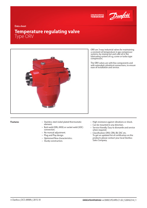
ORV are 3-way industrial valves for maintaining a constant oil temperature in gas compressor systems, by mixing hot and cold oil in the lubricating system of e.g. screw or turbo type compressors.The ORV valves are with few components and with extended cylindrical connections, to ensure ease of installation and service.Features• Stainless steel nickel plated thermostaticelement.• Butt-weld (DIN, ANSI) or socket weld (SOC)connection.• No manual adjustment.• Plug and Play design.• Optimised flow characteristics.• Sturdy construction.• High resistance against vibrations or shock.• Can be mounted in any direction.• Service friendly. Easy to dismantle and service when required.• Classification: DNV, CRN, BV, EAC etc.To get an updated list of certification on the products please contact your local Danfoss Sales Company.Technical data Oils:Applicable to all common refrigeration oils.Refrigerants:Applicable to HC, HCFC, HFC, R717 (Ammonia)and R744 (CO2).For further information please refer to installationinstruction for ORV.Temperature range:Minimum operating temperature:≥ –10°C (+14°F)Max. temperature limit based on the element temperature settings:Types Max limit43°C / 110°F77°C / 170°F49°C / 120°F82°C / 180°F60°C / 140°F93°C / 200°F77°C / 170°F110°C / 230°FPressure range:The valves are designed for a max.working pressure of 40 bar g (580 psig)Design IdentificationConnectionsAvailable with the following connections:• Butt weld DIN (EN 10220),DN 25-80 (1-3 in.)• Butt weld ANSI (B 36.10 Schedule 80),DN 25 - 40 (1 - 1½ in.)• Butt weld ANSI (B 36.10 Schedule 40),DN 50 - 80 (2 - 3 in.)• Socket Weld (ANSI B 16.11),DN 25 - 50 (1 - 2 in.)HousingMade of special, cold resistant steel approved forlow temperature operations.InstallationInstallation of the valve depends on the way itshould operate.Pressure Equipment Directive (PED)ORV valves are approved according to theEuropean standard specified in the PressureEquipment Directive and are CE marked.For further details / restrictions - see InstallationInstruction.FunctionMixing operationORV valve can work as a mixing or diverting valve. The ORV temperature regulating valve utilises the high coefficient of thermal expansion of wax to create the internal movementnecessary to have a cold and a hot inlet mixing to a common outlet. The outlet temperature will correspond to the nominal temperature of the thermostatic element.The valve house has three ports:• Port A is used for the common outlet • Port B is for the hot inlet •Port C is for the cold inletWhen the compressor unit is cold at start up, the thermostatic element will be contracted to let the full flow from port B pass until the nominal temperature (minus 5 K / 10°F ) is reached (fig. 1.1). The thermostatic element will then begin to extract to let the outlet become a mixture of hot and cold oil.When the nominal temperature is reached, the element is positioned in approximately half open position (fig. 1.2). If the temperature is reaching approximately the nominal temperature plus 5 K, the thermostatic element has been extracted to its fully open position (fig. 1.3). In this position the oil temperature will only come from the cold inlet port (C) from oil cooler.From figure 1, it can be seen how the sleeve on the element is sliding in a vertical movement. The thermostatic element is kept in position by a spring.Diverting operationDiverting operation is similar to the mixing operation. It is carried out with separation in to two of the fluid with single temperature. Due to that the temperature on the inlet is very stable fact the regulation is very smooth. The inlet temperature would correspond to the nominaltemperature of the thermostatic element.The valve house has three ports:• Port A is used for the common inlet • Port B is for the cold outlet • Port C is for the warm outletThe diverting operation otherwise is similar to the mixing operation.Application examplesExample of the system with ORV for diverting operationCapacitiesSI unitsSelection exampleOil type: Grade 68Required flow: 17 m3/hNominal oil temperature: 49°CPipe dimension: 40 mmThe upper left curve shows the viscosity of different grades of oil as a function of the temperature. The viscosity is continued into the upper right curve where the 17 m3/h must be found. The line is drawn vertically downwards into the capacity table for the ORV valve models.As shown two selections can be made:Either ORV 40 H2 with pressure drop at approx. 0.56 bar or ORV 50 H2 with pressure drop at 0.42 bar.The final selection will depend on the available pressures in the system. If the pressures are low (or can be low at certain loads) the ORV 50 H2 might be preferred. If the pressures are constantly available the pipe dimension may be taken into account and the ORV 40 H2might be preferred.CapacitiesUS unitsSelection exampleOil type: Grade 68Required flow: 75 USgal/min.Nominal oil temperature: 120°FPipe dimension: 1½”The upper left curve shows the viscosity of different grades of oil as a function of the temperature. The viscosity is continued into the upper right curve where the 75 USgal/min. must be found. The line is drawn vertically downwards into the capacity table for the ORV valve models.As shown two selections can be made:Either- ORV 1½H2 with pressure drop 8.2 psi or- ORV 2”H2 with pressure drop 6.2 psiThe final selection will depend on the available pressures in the system. If the pressures are low (or can be low at certain loads) the ORV 2" H2 might be preferred. If the pressures are constantly available the pipe dimension may be taken into account and the ORV 1½" H2might be preferred.Material specification ORV 25-80No.Part Material EN ASTM standard1Housing Steel GP240GH10213-2WCB A 2162Cover Steel GP240GH------------------------P285QH 10213-2------------------------10222-4WCB A 216------------------------A 3503Glide ring PTFE4Element*)Stainless steeland NI platedparts5Spring Steel DIN1722310270-16Gasket Non asbestos7Bolts Steel Quality 8.8ISO4017Grade 5*) The thermostatic element may look differently from one shown on the picture. All types of thermostats used by Danfoss have the same function, temperature setting and P-band.Connections DINANSISOCDimensions and weightsType codesImportant!Where products need to be certified according to specific certification societies or where higher pressures are required, the relevant information should be included at the time of ordering.Valve type ORV Oil regulating valve, high specificationNominal size in mm(valve size measured on the connection diameter)Available connections DINANSI SOC 25X X X 40X X X 50X X X65X X 80XXConnection A D SOC Butt weld connection: ANSI Butt weld connection: DIN Socket welding Valve housing3-WAY3-WAYThermostatCode no.Thermostat 43oC/110oFORV 25 and ORV 40 H1148H3466ORV 40 and ORV 50 H2148H3467ORV 65 and ORV 80 H3148H34681)Thermostat 49o C/120oFORV 25 and ORV 40 H1148H3463ORV 40 and ORV 50 H2148H3464ORV 65 and ORV 80 H3148H34651)Thermostat 60o C/140oFORV 25 and ORV 40 H1148H3469ORV 40 and ORV 50 H2148H3470ORV 65 and ORV 80 H3148H34711)Thermostat 77o C/170oFORV 25 and ORV 40 H1148H3472ORV 40 and ORV 50 H2148H3473ORV 65 and ORV 80 H3148H34741)1)For valve housing size H3 the code number includes two H2 thermostats.Complete valve housing including gasket and guide ring but without thermostat Code no.ORV 25 DIN H1148H3399ORV 25 SOC H1148H3400ORV 25 ANSI H1148H3401ORV 40 DIN H1148H3361ORV 40 DIN H2148H3402ORV 40 SOC H2148H3403OVR 40 ANSI H1148H3404ORV 40 ANSI H2148H3405ORV 50 DIN H2148H3406ORV 50 SOC H2148H3407ORV 50 ANSI H2148H3408ORV 65 DIN H3148H3409ORV 65 ANSI H3148H3410ORV 80 DIN H3148H3362ORV 80 ANSI H3148H3411ORV parts programmeExample:ORV 40 DIN H2 49°C/120°F:Thermostat element and cover gasket code number 148H3464andComplete valve housing code number 148H3402Ordering ORV valves from the parts programmePlease note:The thermostat code numbers do not include guide ring.Gasket and guide ring are included when ordering the complete valve housing but can also be ordered separately as spare parts.PartSpare parts for Code no.Gasket and guide ringORV 25 and ORV 40 H1148H3246ORV 40 and ORV 50 H2148H3247ORV 65 and ORV 80 H3148H32482)2)Including two guide rings and one gasket.ORV spare partsData sheet | Temperature regulating valve, type ORV。
丹佛斯电动调节阀

高效节能方案
提供全面的节能解决方案,帮助企 业优化能源利用,降低运营成本。
符合环保要求
节能性符合国家环保要求,有助于 企业实现绿色可持续发展。
04
使用与维护
使用方法
开启与关闭
在接通电源后,按下控制面板上的开启或关闭按钮,阀门即可动 作。
调节流量
通过控制面板上的调节旋钮或输入控制信号,可以调节阀门的开 度,从而控制流量。
高效节能
高效节能技术将进一步应用于电动调节阀,降低 能耗,提高能源利用效率。
3
可靠性提升
通过材料、工艺和设计的改进,提高电动调节阀 的可靠性和寿命,减少维护和更换的频率。
市场前景分析
市场需求增长
随着工业自动化程度的提高和节能减排的需 求,电动调节阀的市场需求将持续增长。
竞争格局变化
随着新技术的出现和市场需求的增长,电动调节阀 行业的竞争格局将发生变化,优质企业将获得更多 市场份额。
阀门无法动作
可能是电源故障或电机损坏,应检查电源和电机 是否正常工作。
阀门泄漏
可能是密封件老化或损坏,应更换密封件。
阀门卡死
可能是润滑不良或异物堵塞,应加注润滑油或清 除异物。
05
丹佛斯电动调节阀与其他调节阀 的比较
与气动调节阀的比较
能源效率
丹佛斯电动调节阀通常比气动调节阀更节能,因为它们不需要压缩 空气或气体,从而减少了能源消耗。
维护成本
气动调节阀需要定期更换空气过滤器和密封件,而电动调节阀的维 护成本相对较低,因为它们结构简单且部件较少。
控制精度
气动调节阀在控制精度方面可能不如电动调节阀,因为气体的压力和 流量可能会受到环境因素的影响,而电动调节阀的控制精度更高。
丹佛斯 ICAD电动马达操作指南
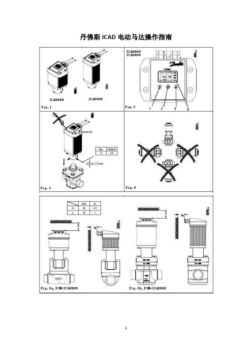
丹佛斯ICAD电动马达操作指南安装使用ICAD600和电器参数供电电源在输入/输出间具有直流隔离保护供电电压:24Vd.c.+10%/-15%负载:ICAD600:1.2A ICAD900:2.0A失效保护供应最小:19Vd.c.负载:ICAD600:1.2A ICAD900:2.0A模拟输入——电流或电压电流:0/4~20Ma负载:200Ω电压:0/2~10Vd.c.负载:10kΩ模拟输出:0/4~20mA负载:≤250Ω数字输入——可以通过无源触点提供开关量信号输入(推荐使用镀金触电的继电器)——电压输入被使用ON:接触阻抗<50ΩOFF:接触阻抗>100Ω数字输出:3位NPN开关管输出外部供电:5~24Vd.c.(相同的供电电压可以作为ICAD的供电,但请注意这将导致直流隔离保护的失效)输出负载:50 Ω负载:最大50Ma温度范围(环境):-30℃/+50℃防护等级:IP65(~NEMA4)电缆连接:两条1.8米电缆预先安装供电电缆:3芯0.34mm2(3X~22AWG) Ф4.4mm (fig.6)Ⅰ:白色(+)19~24Vd.c.失效保护供应(可选择)Ⅱ:褐色(+)24Vd.c.Ⅲ:绿色(-)24Vd.c.控制电缆:7芯0.25mm2(7X~24AWG) Ф5.2mm (fig.7)A:白色(-)数字输出一般报警B:褐色(-)数字输出 ICM全开C:绿色(-)数字输出 ICM全闭D:黄色(-)接地E:灰色(+)模拟输入0/4~20mAF:粉红色(+)模拟输入0/2~10V/数字开/关输入G:蓝色(+)模拟输出0/4~20mA电器安装ICAD600/900安装在所有ICM阀上的过程。
做好所有必要的电器连接,ICM阀的模拟或数字操作。
Fig.6■模拟操作——7线缆(A~G)模块控制。
ICM阀通过丹佛斯电器控制,型号EKC347(fig.7),或第三方电器控制(例如PLC)。
——连接模拟输入信号。
丹福斯(Danfoss)方向式阀门产品说明书
Revised 10/01/88I–3557-SWet Armature Solenoid Operated Directional ValveDG4S*-01*A-W(3)-*-50Service GuideVickers by Danfoss®Directional ValvesAX439457235961en-000101’d) (F3 Viton - 5 req’d)Model CodePrinted in U.S.A.For satisfactory service life of these components, use full ow ltration to provide uid which meets ISO cleanliness code 20/18/15 or cleane r. Selections from Danfoss OF P, OFR, and OFRS series are recommended.Danfoss Power Solutions is a global manufacturer and supplier of high-quality hydraulic and electric components. We specialize in providing state-of-the-art technology and solutions marine sector. Building on our extensive applications expertise, we work closely with you to ensure exceptional performance for a broad range of applications. We help you and other customers around the world speed up system development, reduce costs and bring vehicles and vessels to market faster.Danfoss Power Solutions – your strongest partner in mobile hydraulics and mobile Go to for further product information.outstanding performance. And with an extensive network of Global Service Partners, we also provide you with comprehensive global service for all of our components.Local address:DanfossPower Solutions GmbH & Co. OHG Krokamp 35D-24539 Neumünster, Germany Phone: +49 4321 871 0DanfossPower Solutions ApS Nordborgvej 81DK-6430 Nordborg, Denmark Phone: +45 7488 2222DanfossPower Solutions (US) Company 2800 East 13th Street Ames, IA 50010, USA Phone: +1 515 239 6000DanfossPower Solutions Trading (Shanghai) Co., Ltd.Building #22, No. 1000 Jin Hai Rd Jin Qiao, Pudong New District Shanghai, China 201206Phone: +86 21 2080 6201Danfoss can accept no responsibility for possible errors in catalogues, brochures and other printed material. Danfoss reserves the right to alter its products without notice. This also applies to productsagreed.All trademarks in this material are property of the respective companies. Danfoss and the Danfoss logotype are trademarks of Danfoss A/S. All rights reserved.© Danfoss | December 2022•Cartridge valves •DCV directional control valves•Electric converters •Electric machines •Electric motors •Gear motors •Gear pumps •Hydraulic integrated circuits (HICs)•Hydrostatic motors •Hydrostatic pumps •Orbital motors •PLUS+1® controllers •PLUS+1® displays •PLUS+1® joysticks and pedals•PLUS+1® operator interfaces•PLUS+1® sensors •PLUS+1® software •PLUS+1® software services,support and training •Position controls and sensors•PVG proportional valves •Steering components and systems •TelematicsHydro-GearDaikin-Sauer-Danfoss。
丹佛斯VF6000系列蝶阀与电动执行器说明书

3VF6000 Series Butterfly Valve and ActuatorVF6000 Series butterfly valve and VA300 actuator are designed to shutoff or regulate the flow of hot or chilled water in Heating, Ventilation and Air Conditioning (HVAC) system. This series covers models from DN50 to DN600 with either on/off or modulating output via various actuators.Actuators and valves are calibrated in the factory and are packed separately for ease of delivery and installation.Features and BenefitsOptions of Valve and ActuatorFigure 1.VF6000 Series Butterfly Valve and Actuator*Please refer to page 11 for the detailed valve and actuator combinationModel SelectionTable 1: VF6000 Series ValveTable 1: Ordering data of VF6000 Series Butterfly Valve and ActuatorTable 2: VA300 Series Actuators4SpecificationTable 3: VA300 Actuator performance summary56Table 4: Valve performanceInstallationMechanical InstallationElectric Wiring (VA300)NOTE: Ensure that the pipeline and flange faces are clean. Pipescale, metal chips, welding slag, and welding rods can obstruct disc movement and damage the disc and seat.NOTE: Wiring must be conducted by qualified technical staff.Read Installation Manual before wiring.WARNING: Risk of Electrical Shock. Disconnect the powersupply before making electrical connections. Contact with components carrying hazardous voltage can cause electrical shock and may result in severe personal injury or deathFor IP67 actuator wiring:6~12mm cable for type VA301.. 10~14mm cable for type VA302~VA310..Remove the protective cover by the screws on thecoverConduct the terminal wiring according to theinstallation manualCheck wiring again and power onTrail run the actuator and check the operationdirection and limiterPut on the protective cover again7Valve Dimension and WeightFigure 2. Valve DimensionTable 5: Valve dimension (mm) and weight (kg)VA300 Actuator Dimension02BDCN型89M9000-618-C Dimension10Table 6: Actuator Dimension*: Only On/Off Model available, no hand wheel for Model 01. Manual On/Off by using 8” wrench. Hand wheel is available for other Models of both On/Off and Modulating Control.Wiring DiagramFigure 4. Wiring diagram for On/off Actuator (Model Ended with BDC)Figure 5. Wiring diagram for Modulating Actuator (Model Ended with CDC)Figure 6. Signal Switch Over directionI/O Signal Switch OverDEFAULTControl Board Chart (Signal Switch Over Position)AC220V AC220V Input (Default)4-20mA ControlOutput (Default)4-20mA Feed back4-20mAOutput Load=250Ω4-20mAInput Resistor=250ΩN LGG123456I+I-O+O-G r o u n d i n gG r o u n d i n gI n p u t C u r r e n tV a l v e P o s i t i o n F e e d b a c k O p e S h u O p e n i n g E n C l o s i n g E n 1K P o s i t i o n F e e d b a c k P o t e n t i o m e n t e NLO p e n i n g E n d S w i t c C l o s i n g E n d S w i t cUser wiring (dashed)VF6000 Valve and VA300 Actuator match table Table7: On/Off Type SummaryTable8: Modulating Type Summary11Printed on recycled paper© 2013 Johnson Controls, Inc.PUBL-XXXX(XXXX)Johnson Controls is a global diversified technology and industrial leader serving customers in morethan 150 countries. Our 168,000 employees create quality products, services and solutions to optimize energy and operational efficiencies of buildings; lead-acid automotive batteries and advanced batteries for hybrid and electric vehicles; and interior systems for automobiles. Our commitment to sustainability dates back to our roots in 1885, with the invention of the first electric room thermostat. Through our growth strategies and by increasing market share we are committed to delivering value to shareholders and making our customers successful. In 2013, Corporate Responsibility Magazine recognized Johnson Controls as the #14 company in its annual “100 Best Corporate Citizens” list. For additional information,please visit .Johnson Controls Building Efficiency delivers products, services and solutions that increaseenergy efficiency and lower operating costs in buildings for more than one million customers. Operating from 500 branch offices in more than 150 countries, we are a leading provider of equipment, controls and services for heating, ventilating, air-conditioning, refrigeration and security systems. We have been involved in more than 500 renewable energy projects including solar, wind and geothermal technologies.Our solutions have reduced carbon dioxide emissions by 16 million metric tons and generated savings of $7.5 billion since 2000. Many of the world’s largest companies rely on us to manage 1.8 billion square feet of their commercial real estate.Asia Engineering Centre: Wuxi, ChinaShanghai Distribution Center: Shanghai, ChinaAsia Centre of Excellence in Engineering (CoEE): Beijing, China · Mumbai & Pune, India Manufacturing/Assembly: Guangzhou & Wuxi, China · Pune, IndiaThailandTel : +66 (2) 717 1260-80Fax: +66 (2) 717 0861MalaysiaTel : +60 (3) 7628 4393Fax: +60 (3) 7620 0538IndonesiaTel : +62 (21) 5366 8500Fax: +62 (21) 5366 8300AustraliaTel : +61 (2) 9805 8300Fax: +61 (2) 9889 3016New ZealandTel : +64 (9) 444 6434Fax: +64 (9) 444 2092JapanTel : +81 (3) 5738 6100Fax: +81 (3) 5738 6298China (Shanghai)Tel : +86 (21) 6276 6509Fax: +86 (21) 6277 3543SingaporeTel : +65 6748 0202Fax: +65 6284 3017KoreaTel : +82 (2) 554 5935Fax: +82 (2) 554 5739Hong KongTel : +852 2590 0012Fax: +852 2516 5648MacauTel : +853 2875 1820Fax: +853 2875 1825IndiaTel : +91 (22) 3082 2200Fax: +91 (22) 3088 1592Information contained herein including but not limited to the product design, specification or appearance is subject to change without notice. This document is for reference only, please refer to the actual product when buying.PUBL-6783(0613)。
丹佛斯小型电子膨胀阀ETS6 技术资料英文
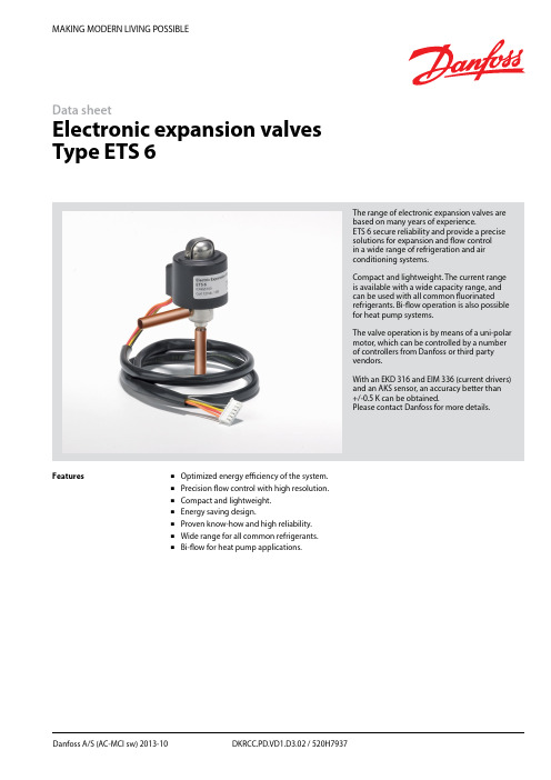
MAKING MODERN LIVING POSSIBLEDanfoss A/S (AC-MCI sw) 2013-10 DKRCC.PD.VD1.D3.02 / 520H7937Data sheetElectronic expansion valves Type ETS 6The range of electronic expansion valves are based on many years of experience.ETS 6 secure reliability and provide a precise solutions for ex p ansion and flow control in a wide range of refrigeration and air conditioning systems.Compact and lightweight. The current range is available with a wide capacity range, and can be used with all common fluorinated refrigerants. Bi-flow operation is also possible for heat pump systems.The valve operation is by means of a uni-polar motor, which can be controlled by a number of controllers from Danfoss or third party vendors.With an EKD 316 and EIM 336 (current drivers) and an AKS sensor, an accuracy better than +/-0.5 K can be obtained.Please contact Danfoss for more details.FeaturesOptimized energy efficiency of the system. Precision flow control with high resolution. Compact and lightweight. Energy saving design.Proven know-how and high reliability. Wide range for all common refrigerants. Bi-flow for heat pump applications.2DKRCC.PD.VD1.D3.02 / 520H7937Danfoss A/S (AC-MCI sw) 2013-10Data sheetElectronic Expansion Valves, type ETS 6Design/functionThe ETS 6 electronic expansion valves open and close to regulate refrigerant flow by means of a screw, whose rotating motion is transformed into linear motion. This occurs by the rotation of a magnet-needle valve assembly whichmoves when electrical signals are applied to the surrounding coil.Within the coil structure, there are different winding configurations, and the polarities arechanged by the electrical signals applied. By application of the appropriate combination of signals, in the form of pulses, the coil forces the rotor of the valve to move in a stepwise fashion.Application of multiple pulses will make the valve mechanism to move through a series of steps in the chosen direction, in order to set the valve with the required opening degree.CoilPermanent magnet motorNeedle valveValve bodyCross section diagram of ETS 6 series* Refers to refrigerant flow in cooling modeOutlet (A*)Inlet (B*)Technical dataFig. 1ApprovalsComplies with: EC PED 97/23/EC a3P3UL, RoHS and CQCRoHSData sheet Electronic Expansion Valves, type ETS 6Danfoss A/S (AC-MCI sw) 2013-10 DKRCC.PD.VD1.D3.02 / 520H79373Electrical wiringStepper motor switch sequenceThe illustration shows the JST XHP-6 connetor. The coil with JST XHP-5 is identical except that it does not have an unused pinCT=38°C, ET=5°C, SC=0°C, SH=0°C*Please contact Danfoss if higher maximum reverse pressure valve is required.1) Max. Reverse Pressure = Pressure as which the valve can still close tightly in reverse direction (from A to B see fig. 1).Valve ordering4 DKRCC.PD.VD1.D3.02 / 520H7937 Danfoss A/S (AC-MCI sw) 2013-10Data sheetElectronic Expansion Valves, type ETS 6For optimum performance, it is important to correct the evaporator capacity. In order toselect the correct size of ETS 6 you will need the following information:Refrigerant: HCFC or HFCEvaporator capacity Q e in kW or TR Evaporating temperature t e in °C or °F Condenser temperature t c in °C or °F Subcooling Δt sub in K or °F ExampleWhen selecting the valve it may be necessary to apply a correction factor to the actual evaporator capacity. This correction factor is required when system conditions are different than tableconditions. Selection also depends on having an acceptable pressure drop across the valve. In the selection table, the pressure drop in the liquid line is assumed to be zero. The following example illustrates correct selection of the valve.Refrigerant: R407CEvaporator capacity: Q e = 10 kW (2.84TR)Condensing temperature: t c = 40°C (104 °F) Evaporating temperature: t e = +10°C (50°F) Subcooling Δt sub = 10 KApplication exampleValve SelectionHeat pump components in typical system.1. Compressor.2. Controller.3. Four-way valve.4. Temperature sensor.5. Pressure transmitter.6. Cartridge pressure control.7. Evaporator.8. Condenser.9. Temperature sensor.10. Electronic expansion valve.11. Sight glass.12. Liquid line filter drier.Data sheetElectronic Expansion Valves, type ETS 6Danfoss A/S (AC-MCI sw) 2013-10 DKRCC.PD.VD1.D3.02 / 520H7937 5Step 1Determine the correction factor for subcooling Δt sub . From the correction factor table (see below) a subcooling of 10 K, R407C corresponds to a factor of 1.14.Correction factors for subcooling Δt sub .Step 2Corrected evaporator capacity isQ e (Corrected) = 10 kW/1.14 = 8.8 kW (2.5 TR)Step 3Select the appropriate capacity table, R407C, and choose the column for condensing temperature of t c = 40°C (104°F) and evaporating temperature of t e = 10°C (50°F) which will provide anequivalent or greater capacity of 8.8 kW (2.5 TR).ETS 6-18 provides 10.35 kW (2.94 TR), which is the proper selection for this example.Step 4Choose ETS 6-18:Single pack code no. 034G5026 I-pack code no. 034G5024Valve Selection (continued)Rated Capacity (kW)Correction factors for subcooling Δt subThe evaporator capacities used must be corrected if subcooling deviates from 0 K.The corrected capacity can be obtained bydividing the required evaporator capacity by the correction factor below. Selections can then bemade from the tables above.6 DKRCC.PD.VD1.D3.02 / 520H7937 Danfoss A/S (AC-MCI sw) 2013-10Data sheetElectronic Expansion Valves, type ETS 6Rated Capacity (kW)Rated Capacity (kW)Data sheetElectronic Expansion Valves, type ETS 6Danfoss A/S (AC-MCI sw) 2013-10 DKRCC.PD.VD1.D3.02 / 520H79377Rated Capacity (kW)Rated Capacity (kW)Data sheetElectronic Expansion Valves, type ETS 6Rated Capacity (kW)8 DKRCC.PD.VD1.D3.02 / 520H7937 Danfoss A/S (AC-MCI sw) 2013-10Data sheetElectronic Expansion Valves, type ETS 6Danfoss A/S (AC-MCI sw) 2013-10 DKRCC.PD.VD1.D3.02 / 520H79379Rated Capacity (TR)Rated Capacity (TR)10 DKRCC.PD.VD1.D3.02 / 520H7937 Danfoss A/S (AC-MCI sw) 2013-10Data sheetElectronic Expansion Valves, type ETS 6Rated Capacity (TR)Rated Capacity (TR)Data sheetElectronic Expansion Valves, type ETS 6Danfoss A/S (AC-MCI sw) 2013-10 DKRCC.PD.VD1.D3.02 / 520H793711Rated Capacity (TR)Rated Capacity (TR)Data sheet Electronic Expansion Valves, type ETS 6 Capacities, continuedConditionsR410 AT e: 5°CT c: 38°C Subcooling: 0°C Superheat: 0°C(B to A ref. drawing page 1)12 DKRCC.PD.VD1.D3.02 / 520H7937 Danfoss A/S (AC-MCI sw) 2013-10Data sheetElectronic Expansion Valves, type ETS 6Danfoss A/S (AC-MCI sw) 2013-10 DKRCC.PD.VD1.D3.02 / 520H7937 13DimensionsETS 6-10ETS 6-14ETS 6-25ETS 6-32ETS 6-40All dimensions in mmETS 6-18All dimensions in mmRelated Danfoss ProductsWeight: 0.16 kg (complete)。
丹佛斯 AME 435 QM 调节控制执行器 规格书说明书

1SMT/SIVD.CV.S2.02 © Danfoss 09/2014Data sheetActuator for modulating control AME 435 QMActuatorType Supply voltage Code No.AME 435 QM24 VAC/DC082H0171DescriptionAME 435 QM actuator for modulating control is used with pressure independent balancing and control valve type AB-QM from DN 40 to DN 100. The actuator has some special features:• it automatically adapts its stroke to the valve end positions which reduces commissioning timeOrdering • valve flow adjustment feature; flow can be variably-adjusted from linear to logarithmic or opposite.• the advanced design incorporates load related ‘switch-off’ to ensure that actuators and valves are not exposed to overload Main data:• Nominal voltage (AC or DC): - 24 V, 50 Hz/60 Hz • Control input signal: - 0(4)-20 mA - 0(2)-10 V • Force: 400 N • Stroke: 20 mm • Speed (selectable):- 7.5 s/mm - 15 s/mm• Max. medium temperature: 120 °C • Self calibrating • LED signalling• External RESET button • Output signal • Manual operationTechnical dataAccessories-AdapterTypefor valve’s DNfor Actuator Code No.AB-QM adapter (2st generation)40-100AME 15 QM003Z0694AB-QM adapter (1st generation)AME 435 QM065Z0313Power supply V 24 AC/DC; ±10%Power consumption running VA 4,5standby1,2Frequency Hz 50/60Control input Y V 0-10 (2-10); Ri = 95 kΩmA 0-20 (4-20); Ri = 500 ΩOutput signal X V 0-10 (2-10); RL = 650 Ω (maximal load)Closing force N 400Max. stroke mm 20Speeds/mm 7,5 or 15Max. medium temperature °C120Ambient temperature0 … 55Storage and transport temperature –40 … 70Protection class II Grade of enclosure IP 54Weightkg 0,45- marking in accordance with standardsLow Voltage Directive (LVD) 2006/95/EC: EN 60730-1, EN 60730-2-14 EMC Directive 2004/108/EC: EN 61000-6-2, EN 61000-6-32VD.CV.S2.02 © Danfoss 09/2014SMT/SIData sheetActuator for modulating control AME 435 QMInstallationMechanicalNo tool is required to mount actuator on the valve. Installation of the valve with the actuator is allowed in horizontal position or upwards. Installation downwards is not allowed.The actuator must not be installed in anexplosive atmosphere, at ambient temperature lower than 0 °C or at ambient temperature higher than 55 °C. It must not be subject to steam jets, water jets or dripping liquid as well.Note:The actuator may be rotated up to 360° withrespect to the valve stem by loosening the retaining fixture. Once the actuator is placed, retighten the fixture.ElectricalElectrical connections can be accessed by removing the actuator cover. Two cable gland entries without thread (Ø16 and combined Ø16/Ø20) are prepared for cable glands. From factory one entry is provided by rubber cable gland and the other entry is prepared for opening. Note:Cable and cable gland used must not compromise the actuator’s IP rating, and must ensure the connectors are fully strain relieved.Rubber cable gland delivered from factory does not compromise IP rating but it does not provide fully strain relieve according to LVD directive.Please observe local rules and regulations as well.Complete the mechanical and electricalinstallation, set jumper and DIP-switches, then perform the necessary checks and tests:• Apply powerNote that the actuator will now perform automatic Calibrating function • Apply the appropriate control signal and check:- SW7 setting- the actuator drives the valve over the entire stroke length The unit is now fully commissioned.CommissioningAutomatic Calibrating featureThe actuator automatically adapts its stroke to the valve end positions :- when power is applied for the first time or - afterwards by pressing the STAND BY/RESET button for 5 seconds Testing entire valve stroke lengthThe actuator can be driven to the fully-open or closed positions by connecting SN to terminals 1 or 3.The actuator must be dismantled and the elements sorted into various material groups before disposal.Disposal3VD.CV.S2.02 © Danfoss 09/2014SMT/SIData sheetActuator for modulating control AME 435 QMEqual-percentage valve-flow adjustment (SW 7 in position ON )The actuator has a special valve-flowadjustment feature called alpha value. Actuator characteristics can be, by turning the alpha knob counter clockwise (CCW), variably-adjusted from α=1 (linear) to α=0.1.Jumper/DIP switch settingJumper• U/I - Input signal type selector- U position; voltage input is selected - I position; current input is selected Factory setting: jumper is in U position.DIP switchesFactory setting: all switches are in OFF position.• SW 1: Not used• SW 2: Input signal range selector- OFF position; the input signal is in the range from 0-10 V (voltage input) or from 0-20 mA (current input)- ON position; the input signal is in the range from 2-10 V (voltage input) or from 4-20 mA (current input)• SW 3: Direct or Inverse acting selector- OFF position; the actuator is in direct acting mode (stem extracts as voltage increases)- ON position; the actuator is in inverse acting mode (stem retracts as voltage increases)If used with AB-QM valves, SW 3 is recommended to be in OFF position (factory setting).• SW 4: Fast/Slow - Speed selector- OFF position; the actuating speed is 7.5 s/mm• SW 6: Not used• SW 7: LOG/MDF - Logarithmic or modified flow through valve selector- OFF position; .........LOG (α=0.2, factory setting)- ON position; ...........MDF (initial setting: α=1, linear)Explanation:If SW 7 is in OFF position, alpha knob is not activated. Turning alpha knob will not influence α value (α=0.2).If SW 7 is in ON position, α value can be manipulated using alpha knob. MDF initial setting of alpha knob is 1, which means linear setting. Regarding alpha knob setting In order to have optimal control, linearcharacteristics of system (valve, actuator, HEX) is required. This can be assured using theright α value. Appropriate α value depends on temperatures of heating/cooling medium and controlled temperature of heated/cooled medium. Calculate α value according to the Tech Note number VNHUA102 (Setting the right α value).4VD.CV.S2.02 © Danfoss 09/2014SMT/SIData sheetActuator for modulating control AME 435 QMLed signalling/Actuator operating modesLED function indicatorThe bi-colour (green/red) LED function indicator is located on the actuator cover. It indicates the operating modes.External buttonActuator has external STAND BY/RESET button which is located next to LED indicator. By pressing on this button different operating modes are initiated:• Calibrating modePressing the STAND BY/RESET button for 5 sec. causes the actuator to start Calibrating procedure :The bi-colour LED flashes green at 1 sec.intervals during calibration procedure, which begins by extracting the stem. When the maximum force is detected (at the end valve position), the actuator then retracts thestem, until the maximum force is once again detected (on the other valve end position). The actuator will then enter to normal mode and respond to the control signal.• Positioning modeThe bi-colour LED is green and stays onduring positioning of the actuator according to the control signal • Normal modeWhen the positioning of the actuator is finished the LED flashes green every 6 seconds.• STAND BY modePressing the STAND BY/RESET button switches the actuator to STAND BY mode. The actuator keeps its last position in this mode and does not react to any control signal. This mode can be used for manual operation during the commissioning of other equipment, or for service purposes.The bi-colour LED flashes red at 2 sec. intervals.After pressing the STAND BY/RESET button again actuator switches to normal mode.5VD.CV.S2.02 © Danfoss 09/2014SMT/SIData sheetActuator for modulating control AME 435 QMManual overrideManual override is done by means of control knob on actuator housing:• Disconnect power supply or press STAND BY/RESET button• Adjust valve position using the control knob (observe the rotation direction)When manual override is not needed:• Restore power supply or press STAND BY/RESET button again Remark:When the manual override has been used, the output signal (X) is not correct until the actuator reaches its end position.Wiring 24 VAC/DC onlySP 24 VAC/DC .............. Power supply SN0 V mon Y 0-10 V ........................Input signal (2-10 V) 0-20 mA (4-20 mA)X 0-10 V ........................Output signal (2-10 V)1, 3Override input signalThe actuator can be driven to the fully-open position by connecting SN to terminal 1 or fully-closed by connecting SN to terminal 3.Signal 1 can be connected to thermostat to prevent freezing and signal 3 can be connected to thermostat to prevent overheating.Wiring length Recommended cross-sectional area of the wiring 0-50 m0.75 mm 2> 50 m1.5 mm 2Important: AME 435QM can be used only for modulating control. For 3-point control useAMV 435 (082H0162/163). It is recommend to use modulating control with AB-QM.6VD.CV.S2.02 © Danfoss 09/2014SMT/SIData sheetActuator for modulating control AME 435 QMDimensionsActuator - valve combinations7VD.CV.S2.02 © Danfoss 09/2014SMT/SIData sheet Actuator for modulating control AME 435 QM8VD.CV.S2.02Produced by Danfoss A/S © 09/2014Data sheet Actuator for modulating control AME 435 QM。
丹福斯方向控制阀值模型31920-31930用户手册说明书
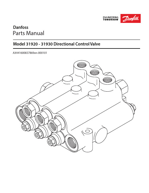
Model 31920 - 31930 Directional Control ValveDanfossParts ManualAX441600837869en-000101Parts DrawingParts ListRef. No.Description Part Number Quantity 1Body NSS12Spool NSS A/R~3O-ring16003-6102/Spool 4Bushing31900-3771/Spool5Washer16048-6131/Spool6Spring, Spool17069-141/Spool7Spacer30900-3131/Spool~8Retaining Ring16009-1051/Spool 9Spool Cap Assembly31900-5691/SpoolBreather Plug16066-4031/Spool~10Wiper Seal16074-1081/Spool 11Relief Valve Plug Assembly31900-665112Lock Nut70411-524113Lock Washer70411-521114Plug31900-6641~15O-ring16133-81†16Shim Washer - .010 inch16048-35A/RShim Washer - .015 inch16048-22A/RShim Washer - .035 inch16048-65A/R 17Relief Valve Spring 118Poppet32015-36119Standard Plug Assembly16169-1120120Standard Plug NSS121Pressure Beyond Plug Assy. (9/16-18 SAE)31900-321122Pressure Beyond Plug (9/16-18 SAE)NSS1Pressure Beyond Plug Assy. (3/4-16 SAE)31900-3411Pressure Beyond Plug (3/4-16 SAE)NSS1 23Closed Center Plug Assembly31900-319124Closed Center Plug NSS1~25O-ring16003-121~26Back-Up Ring16101-2021~27O-ring16015-21 28Check Plunger15440-171/Spool~29O-ring16015-2-902/Spool 30Seat31900-3002/Spool~31Poppet Assembly15440-3172/Spool 32Check Spring31900-5512/Spool33Seat Retaining Plug Assembly with Work Port31900-3101/Spool34Seat Retaining Plug with Work Port NSS1/Spool35Seat Retaining Plug Assembly31900-7071/Spool36Seat Retaining Plug NSS1/Spool~37Back-Up Ring16011-2122/Spool~38O-ring16003-12 - 902/SpoolSeal Repair KitsOne Spool Valves31921-927Two Spool Valves31922-926Three Spool Valves31923-929NSS Not sold separatelyA/R As required† Install the same shim thickness as removed. At least one shim is required.Refer to the table on the back page for speci c part numbers.~ Parts included in Seal Repair Kits.Handle PartsRef. No.DescriptionPart NumberQuantity Handle Kit 31900-9121/Spool 1Handle 31900-70812Handle Cover 16126-8513Handle Link Assy.30501-33114Connecting Link 30501-33215Link Plate 30501-33316Spring Clip 30501-33417Clevis Pin 31900-71118Lever Support 31900-71019Cotter Pin 16027-2031Ref. No. 17Relief Valve SpringPressure Adjustment RangePart Number 450 - 900 PSI17041-22850 - 1100 PSI 17042-171050 - 1250 PSI 17046-151200 - 1650 PSI17044-161600 - 2300 PSI (Standard)17047-312250 - 2500 PSI17049-36Information on ori ce plates is contained in the Ori ce Plate Catalog Sheet, Form 11-502.Danfoss Power Solutions is a global manufacturer and supplier of high-quality hydraulic and electric components. We specialize in providing state-of-the-art technology and solutions that excel in the harsh operating conditions of the mobile off-highway market as well as the marine sector. Building on our extensive applications expertise, we work closely with you to ensure exceptional performance for a broad range of applications. We help you and other customers around the world speed up system development, reduce costs and bring vehicles and vessels to market faster.Danfoss Power Solutions – your strongest partner in mobile hydraulics and mobile electrification.Go to for further product information.We offer you expert worldwide support for ensuring the best possible solutions foroutstanding performance. And with an extensive network of Global Service Partners, we also provide you with comprehensive global service for all of our components.Local address:DanfossPower Solutions GmbH & Co. OHG Krokamp 35D-24539 Neumünster, Germany Phone: +49 4321 871 0DanfossPower Solutions ApS Nordborgvej 81DK-6430 Nordborg, Denmark Phone: +45 7488 2222DanfossPower Solutions (US) Company 2800 East 13th Street Ames, IA 50010, USA Phone: +1 515 239 6000DanfossPower Solutions Trading (Shanghai) Co., Ltd.Building #22, No. 1000 Jin Hai Rd Jin Qiao, Pudong New District Shanghai, China 201206Phone: +86 21 2080 6201Danfoss can accept no responsibility for possible errors in catalogues, brochures and other printed material. Danfoss reserves the right to alter its products without notice. This also applies to products already on order provided that such alterations can be made without subsequent changes being necessary in specifications already agreed.All trademarks in this material are property of the respective companies. Danfoss and the Danfoss logotype are trademarks of Danfoss A/S. All rights reserved.Products we offer:•Cartridge valves •DCV directional control valves•Electric converters •Electric machines •Electric motors •Gear motors •Gear pumps •Hydraulic integrated circuits (HICs)•Hydrostatic motors •Hydrostatic pumps •Orbital motors •PLUS+1® controllers •PLUS+1® displays •PLUS+1® joysticks and pedals•PLUS+1® operator interfaces•PLUS+1® sensors •PLUS+1® software •PLUS+1® software services,support and training •Position controls and sensors•PVG proportional valves •Steering components and systems •TelematicsHydro-GearDaikin-Sauer-Danfoss。
- 1、下载文档前请自行甄别文档内容的完整性,平台不提供额外的编辑、内容补充、找答案等附加服务。
- 2、"仅部分预览"的文档,不可在线预览部分如存在完整性等问题,可反馈申请退款(可完整预览的文档不适用该条件!)。
- 3、如文档侵犯您的权益,请联系客服反馈,我们会尽快为您处理(人工客服工作时间:9:00-18:30)。
接报警装置
感器,控制器及执行机构(如
图1中的电动调节阀)。在水路
楼宇自控系统或当地控制器
系统中,电动调节阀就是最常 用的执行机构。
图1 空气处理机组的控制
电动调节阀基础知识
电动调节阀由驱动器和阀体二部分组成,根据控制器的信号的要求开大或关小阀门,对流量进行 调节,从而实现调节能量的目的。
下面是涉及电动调节阀选型和使用的一些基础知识:
值,可通过公式(3)算出阀门的压降,为水泵选型提
2.阀门串、并联时的总的 与每个阀门 值之间的关系: 阀门并联
阀门串联
公式(4):
公式(5):
公式(4)阀门并联的情况对于平时设计是非常有用的。经常有一些系统需要用到口径很大的调
节阀,如
,而这种大口径的调节阀在市场是很难买到,即使有的话,价格也非常昂贵,而且这
公式(1):
式中: --流经电调阀的流量, 。 Δ --阀前、后的压差, 。
阀门全开时的流通能力最大为 开度相对应。
,全关时为 ,其它开度位置的流通能力用 值表示,与阀门的
电动调节阀 从公式(1)可以引申出二个非常有用的公式(2)和(3):
公式(2):
公式(3):
例如:已知经过阀门的设计流量和阀门的 供依据。
任何阀门都有其固有的流量特性,其反映了阀门的相对流量与相对行程之间的关系。当阀门前后压 差固定不变时所得到的流量特性,称为阀门的理想流量特性。常见的阀门理想流量特性主要有以下四大 类,见图2所示:
电动调节阀
图2 阀门的理想流量特性
①. 直线型:单位行程变化引起的流量变化相等。小流量时流量的 变化大,不易微调与控制,配合不好时会产生振荡。
四、驱动器其它功能 1、阀位显示功能,在外部可观察到阀门的开度位置; 2、可改变阀门最大行程,使得阀门的kvs更接近设计需要; 3、阀门正反向动作设定,能够方便地满足不同工况的要求; 4、手动操作功能,确保无电状态下的正常操作; 5、驱动器具有 个步进, 使阀门定位更准确;
阀体部分:
一、阀体驱动轴密封设计为可更换型,便于维护;
②. 抛物线型:流量特性为一条二次抛物线,介于直线与等百分比 特性之间。
③. 等百分比型:同样行程在小开度时流量变化小,大开度时流量 变化大,适用于负荷变化幅度较大的系统,也称对数特性型。
④. 快开型:行程较小时,流量就比较大,随着行程的增大流量很 快达到最大。阀的有效行程< ( 为阀座直径)。行程再增 大时已不起调节作用,适用于双位控制。
二、选型表举例
已知:设计流量
,末端设备压降Δ
,
关闭压差要求不小于
,如图9所示:
1、计算法 (1)先确定阀门选型压降:根据阀权度要求,按阀权度
M
图9
进行初选,则:
计算得Δ Δ
,
(2)计算所需 值为:
(3)查第七页快速选型表选阀门,其 为 ,大于 ,满足要求。
值应大于计算出的 值:查得
的值பைடு நூலகம்
(4)校核所选阀门实际的阀权度。如果选用 为 的阀门,此时阀门全开时的实际压降为:
作为在欧洲成长起来的全球领先者,我们非常自豪的将中国作为我们的第二家乡市场。丹佛斯中国有限 公司在北京、上海、广州、天津、青岛、沈阳、成都和重庆设办事处和销售分公司,并在天津武清建有生产工 厂,正如丹佛斯集团在全球制冷、供热和空调及水控制、传动控制等行业已经建立了广泛良好的声誉,丹佛 斯在华生产和销售的所有同类产品,都始终坚持最高的国际质量标准。
这样做的好处是:
(1) 将一个大口径阀门转换成二个常规的小口径阀门,造价反而比一个大口径阀门低; (2) 二个阀门并联后,其口径较大的一个在关闭过程由于有小阀门在旁通,因此便于关闭; (3) 因为在小流量时由小阀门进行调节,因此与一个大阀门相比,提高了在小流量时的调节性能。
二、电动调节阀的理想流量特性曲线
曲线1 时间
时间 曲线2
调节阀开度
时间
图7 系统稳定时间与控制效果的关系
1 当调节阀处于开度较大时(曲线1中的a段),调节阀阀芯大幅度地动作,但盘管的散热量的变化很 小,达到所需温度的控制时间很长;
2 当阀门处于小开度时(曲线1中的b段),调节阀阀芯轻微动作,就导致盘管的散热量的变化很大,形 成震荡控制,系统需要达到稳定的时间很长。
二、特殊的特芯设计以降低噪音水平;
三、阀门的控制比大,达到 : ,即在 开度以上均具有良好的调节性能;
四、与丹佛斯驱动器相配,最小关闭压差均在
以上。
丹佛斯电动调节阀快速选型表
阀 门 阀门+驱动器
口径
型号
驱动器最大 压 降
值 关闭压差
()
压降 ()
经过阀门的流量(
压降 (bar)
压降 (bar)
压降 (bar)
出现的原因是电动调节阀两端的压降过大,尤其当阀门开度较小时,系统压降基本上都降在了阀 门上,其中在阀锥下游的压降会更大。当某点的压力下降到该点水温对应的汽化压力以下时,该点将 发生气化,产生气泡,发生“气蚀”现象,并产生刺耳的嚣叫。这种现象在调节阀压降越大、水温越 高时(主要是冬季)越容易出现。即使没有出现气蚀现象,过大的压降也会导致噪音、振动、驱动器 无法关断阀门等现象。
电动调节阀
公式(6):
图5
2、阀门实际工作流量特性:阀门的理想流量特性是在阀门两端压差保持不变,即阀权度为 时的情 况下得出的。但在实际系统中,阀门在从关到全开这个过程中,两端压差是在变化的。调节阀前后压差 随负荷变化的条件下,调节阀的相对行程与相对流量之间的关系为阀门的工作流量特性。不同的阀权度 下,电动调节阀的工作流量特性不同。图6给出了不同阀门阀权度从 到 时的流量特性曲线:
末端
末端
末端
图8 动态失调导致调节阀频繁动作
电动调节阀
解决方法:采用动态压差平衡阀可防止动态失调。用动态压差平衡阀固定电动调节阀两端或某一
支路的压差,则
,只要电动调节阀的开度不变(负荷没有发生变化)则水量不变,从而
防止了动态失调,防止了电动调节阀频繁动作而影响使用寿命。
丹佛斯电动调节阀主要技术特点
+
=
a
b
c
图4
三、阀权度和调节阀实际工作流量特性的关系
1、阀权度定义:阀门全开时阀门两端的压降与阀门全关时阀门两端的压降之比,也可近似表示为阀 门全开时阀门压降与控制回路总压降的之比,见公式(6)。从理论上说,这个值越大越好,表明阀门能 够对流量进行有效调节从而对能量输出进行有效控制。但在没有其它设施保证其阀权度时,要实现具有 较大的阀权度意味着电动调节阀上的压降要大,这又要消耗较多的水泵扬程,运行不经济,是矛盾的, 因此综合考虑一般取 为 左右(没有动态压差平衡阀时),最低不小于 。
暖通空调水系统能量控制元件
电动调节阀
舒适
食品冷链
节能
环保
-丹佛斯,精“艺”求精
公司简介
丹佛斯公司创立于1933年,1943年发明出世界上第一个散热器恒温控制器。 丹佛斯公司是一家以善于利用先进的制造技术,并关注环保问题而闻名于世的跨国集团,是制冷控制、 供热和空调及水控制,以及传动控制等领域处于世界领先地位的产品制造商和服务供应商。丹佛斯已经在 100多个国家设有国际子公司及代理商网络,在全球拥有56间质量管理控制严格的工厂,每天生产250,000 件高品质产品,180家销售机构,超过18,000位受过良好教育并充满活力的员工,向全球提供行销和服务。 对节能、舒适以及安全的承诺,是丹佛斯公司在行业内处于领先地位的坚实基础。
一、阀门的流通能力
1.定义:阀门的流通能力反映的是阀门的通过能力,其定义为阀两端的压差为 时,通过阀门 的流量,常用 来表示,见公式(1)。当阀门处于全开状态时的流通能力为阀门的最大流通能力,常用
表示。 是阀门的一个特性参数,类似电路中电阻的概念,它只与阀门的结构有关,是一个不变 的值,是厂家必须提供的阀门技术参数之一。
么大的阀门其所需的关闭压差会很大,需要用到力矩很大的驱动器,这也是很难做到的。因此很多工
程遇到这种需求时常常用电动蝶阀代替,这种做法只满足了尺寸安装的要求,而舍弃了最重要的调节
性能。
实际上遇到这种大口径阀门的需求时,通常可以用二个阀门的并联方式解决,通常二个阀门 值
按 和 的关系进行并联匹配,开动作时为先开小阀,后开大阀,关动作时先关大阀,后关小阀。
而如果电动调节阀能保证良好的阀权,处于较理想的控制曲线上(图7中曲线2)时,不论阀门处于何 种开度,系统均能迅速稳定至所需温度。
此问题的解决方法:尽可能增加阀门的阀权度(至少不小于推荐值),必要时使用动态压差平衡阀或 直接采用动态平衡型电动调节阀。
三、电动调节阀动作频繁
原因:动态失调引起电动平衡阀动作频繁。变流量系统由于部分负荷发生变化导致的电动调节阀 开度的变化引起系统压力的波动,从而引起其他负荷没发生变化的末端水量变化,造成了这部分电动 调节阀动作频繁。如图8所示,当某个末端的电动调节阀完全关闭,造成同支路其他末端两端的压差 增大,从而其他负荷没发生变化的末端的电动调节阀因为水量变化也要产生不必要的动作。
驱动器部分:
一、驱动器控制信号灵活
丹佛斯驱动器可接收 -
、-
、 - 、 - 任一种控制信号;输出信号为
或
;具有输入信号分段功能,能够用一个信号顺序控制两个电动调节阀。
二、驱动器具有行程自检功能。 驱动器第一次通电后能够自动检测阀行程的大小,并将之与相应的控制信号相对应。
三、驱动器具有安全保护功能 1、驱动器具有极限位置力敏开关,对电机起过载保护作用,能够有效地防止烧坏驱动器; 2、驱动器对于接线错误具有保护功能,不会因为接线错误损坏驱动器; 3、有信号灯对驱动器的状态进行显示,如出现的异常,可通过信号灯显示的状态上判断出来。
阀门的各种流量特性是通过不同的阀芯形状来实现的,如图3所示: