MIPI协议详细介绍PPT课件
MIPI协议详细介绍

establishing Spec.
❖ Board Members in MIPI Alliance
▪ Intel, Motorola, Nokia, NXP,Samsung, ST, TI
What is MIPI?
❖ MIPI Alliance Specification for display
▪ DCS (Display Command Set)
• DCS is a standardized command set intended for command mode display modules.
❖ D-PHY low-level protocol specifies a minimum data unit of one byte
▪ A transmitter shall send data LSB first, MSB last.
❖ D-PHY suited for mobile applications
Clock to the Slave side
❖ End-of-Transmission
▪ H Toggles differential state immediately after last payload data bit
❖ and keeps that state for a time THS-TRAIL
❖ Three main lane types
▪ Unidirectional Clock Lane ▪ Unidirectional Data Lane ▪ Bi-directional Data Lane
MIPI-DSI-Essential(MIPI协议详细介绍)演示课件

MIPI DSI EssentialTable of Contents •MIPI DSI Overview•PHY Layer–D-PHY Architecture–Global Operation •Lane Management Layer •DSI Protocol LayerMIPI DSI Overview•Serial Interface– Low Pin Count– Reduced Power Consumption•2 Types of Data Signaling–High Speed Data Transmission - 500Mbps/Lane, differential signaling–Low Power Data Transmission - 10Mbps, single ended signaling, lane 0 only •Lane-Scalable, up to 4 data lanes •Packet Based Data Transmission–DSI Protocol has ECC, CRC capability - robust data transmission–Protocol Support Multiple displays (up to 4)MIPI DSI Interface Physical Architecture■ 1 Clock Lane, unidirectional■ 1 to 4 Data Lanes■ Lane0 is bidirectional for LP data output transmission of the driver ICMIPI DSI Functional LayersTransmitter Side8-bits8-bitsLow Level ProtocolDataControlData Control Add (TX) / Extract (RX) low levelprotocol, synchronization, ECC, CRC packet headers and footers.Low Level ProtocolDataControlData Control N * 8-bitsTX: Distribute data to 1, 2, 3 or 4 lanes RX: Assembly data from 1, 2, 3 or 4 to onebyte stream 8-bits8-bitsLane Management LayerLane Management LayerReceiver SidePHY Layer Data3ControlPHY LayerControlPixel to Byte Packing FormatsDataControlPixel Control Pack / Unpack Pixels or Commandsfrom / to Byte Stream Byte to Pixel Unpacking FormatsDataControlPixel Control ApplicationPixelControlApplicationPixelControlEncode and Interpretat Data /Commands16-, 18- or 24-bit PixelsData2Data1Data0N * 8-bitsData1Data3Data3Data0High Speed Unidirectional Clock Lane 0 -High Speed bidirectional Data Lane 1 -High Speed Unidirectional Data Lane 2 -High Speed Unidirectional Data Lane 3 -High Speed Unidirectional DataPhysical Transmission / ReceptionSerializer / DeserializerByte Clock Generation / Recovery (DDR)per MIPI D-PHY SpecVideo Mode DisplayDisplay DriverHost ProcessorDisplay PanelLCD DisplayBus InterfaceBus InterfaceColor Frame BufferDisplay RefreshTiming ControlUpdate Frame BufferHS Mode Operation in Practice - LPDT to HSDTLP01LP00LP11LP Transmitter DrivingHS Transmitter DrivingHS ClockR-term OnDPDNHS Mode Operation in Practice - SOTSOTDATA000011101ClkDataBus Turn Around•Handover Bus Possession–Host to client, client to host–When host request data from client and whenhost read status of client–Client must send BTA after client's datatransmission–TE-signaling•Sequence (ex, Read Request to Client)–Host Send "Read Request" to Client -> Host sends BTA -> Client Get Bus -> Host Releases Bus ->Client sends data -> Client sends BTA -> HostGet BusBus Turn Aroundin PracticeBTAClient LPDTHost DrivingClient DrivingDPDNLane Management LayerMulti Lane Distributionand MergingDistributor Merger Function(receive)DSI Protocol LayerPacket-basedProtocol•Data Flow–Image data, Signal events, Commands ->Protocol Layer -> Packets ->Physical layer -> Packet Receive -> Interpret Packet to Image data,Signal Event, Commands–Signal Event : V-sync, H-sync.–Commands : DCS Commands•Many packets can be transferred in a transmissionECC Generation- DI - Data 0- Data 1ECCCRC Calculation- DataCRCECC Generation- DI- Word CountECCEndian Policy •Long Packet Case–LS Byte First, MS Byte LastVirtual Channel•Up to 4 peripherals possible with tagged command or blocks of data, using the Virtual Channel ID Field–DSI hub is needed, Not possible to connect many display to same bus DSI HubHost ProcessorMain Display Panel LCDDisplayBus InterfaceBusInterfaceDSIOut 1Out 2InterfaceLCD DisplayFrame BufferSub- DisplayMultiple Packets perTransmission- With EoTp- Without EoTpOnly Video ModeVideo Mode Command ModeMotorola Legacy operation for videomodeProtocol SpecificOnly Video ModeVideo Mode Command Mode Protocol SpecificPackets for DCScommands•DCS Short Write : write a single data byte to a peripheral–05h / 15h (no parameters /one parameter)–If BTA follows ACK by display or AwER•DCS Long Write / write_LUT Command, Data Type = 11 1001 (39h)–Used to send larger blocks of data to a displaymodule–DI byte, a two-byte WC, an ECC byte, followedby the DCS Command Byte, a payload of lengthPackets for DSIProtocol•Set Maximum Return Packet Size, Data Type = 11 0111 (37h)–This prevents FIFO overflow for Read packetpayload in processor, considering the case that–Memory read command can retrieve a numerous bytes of data.•Null Packet (Long), Data Type = 00 1001 (09h)– This prevents the data lane(s) going back to LP-11, with less overhead to continue HS burst.Packets forVideomode•Sync Event : generate video sync signal internally–V Sync Start(0x01), V Sync End(0x11)–H Sync Start(0x21), H Sync End(0x31)•Video Streams (Long)–RGB Video StreamsRGB Pixel Stream -16bit, 24bit24-Bit PixelData Type : 0x3E Word Count:1H Line Pixel Length x 316-Bit PixelData Type : 0x0E Word Count:1H Line Pixel Length x 2Video Streaming - Non Burst OperationVideo Streaming - BurstOperationReverseTransmissions•Occur on D0 after host has made BTA•Display is expected to reply data or at least reply ACK–ACK means everything's ok•Response Type–Tearing Effect (TEE)–Acknowledge = ACK–Acknowledge and Error Report = AwERReverse Response Data TypeLPDT Reverse Example11100001=LPDT Data type 05 =short write noparams 00010001= 0x11=SLPOUTECCBTADisplay EMEdphy table 8 : ACK =00100001 (0x84)BTA back to hostError Detect and Reporting■Error Bit MappingQnACommand ModeDisplayHost ProcessorDisplay PanelLCD DisplayBus InterfaceColor Frame BufferImage Update DataCommands & Image UpdateDataBus InterfaceDisplay ControllerPHY Layer D-PHY ArchitecturePHY Lane Configuration•Minimum Configuration–At least 1 Clock Lane, 1 Data Lane •Reverse-direction traffic uses lane 0 only–Lane 1, 2, 3 (if present)are unidirectional •Lane number fixed at design / manufacture(Module level)–No dynamic lane configuration by hostprocessor.•Transmission data Unit–One byte•Lane Module may contain–HS-TX, HS-RX, or both•If LP mode is used at command mode configuration , both host and peripheral must include LP Rx and LP Tx–Also CD needed if bi-directional in use•The LP-CD shall check for contention at least once before driving a new state on the line•Master and a Slave conceptLow power transmitter High speed receiverLow power receiverContention (=“collision”) detectionHigh speed transmitterLeast PHY Lane Configuration -Detailed ViewData lane 0CLK lane* Bi-directional but not HS reverse * LP for bi-directional* uni-directional * LP for minimum transition controlD-PHY Signal Level•2 Types of Signal Level–HSDT–LPDT LP VOH - typ 1.2V, 1.1V ~ 1.3VHS diff - typ 200mv, 140mv ~ 270mvHS comm - typ 200mv, 150mv ~ 250mvLP VOH - typ 0V, -50mV ~ 50mVLP VIL : 550mVLP VIH -typ 1.2v 0.88V ~ 1.35VHS Mode- Transmitter Receiver Structure •HS Data Transmission–While HSDT is active, Termination R is enabledR-term(ZID) : 100OhmTransmitter side Receiver sidePCB, Conn, FPCB 0V400mV 300mV100mVHS Mode - Signaling Detailed View300mv 100mv 200mv100mv200mvV diff = |V OD|■Vdiff 200mV, Vcm 200mV Typ ConditionHS Mode - Clock Transmission•HS Clock–DDR Clock Structure, 1 Clk Period : 2*UI–Clock Burst always contains an even number oftransition–Clock can also run while D0 is in LP mode(especially Videomode)•Ex) 500Mbps–Freq : 250Mhz, 1Clk Period : 4ns, IU = 2ns,HS Mode - Clockto Data•Data to Clock Timing Definition–90 Degree Phase Shift CLK to Data–The First bit of DSI Packet must be sent at arising edge of HS ClkData LaneClock LaneHSDT Signal inPracticeVo+ : typically ~300mVVCM = 200mV nomVo- : typically ~100mVVdiff(positive)LP Signaling Detailed View •Typically 1.2V•T LPX - min : 50nsLPDT Signal in Practice2T LPXtypically 1.2V DPDNPHY Layer Global OperationData Unit Of D-PHY•Minimum Data Unit is 1 Byte–Transmitter - Byte stream -> Bit stream–Receiver - Bit stream -> Byte stream•HS Lane can be differential 1 or 0•LP Lane on D0 can have four state(LP +/-)–LP00 : "Bridge", "Space"–LP01 : "HS-Rqst", "Mark-0"–LP10 : "LP-Rqst", "Mart-1"。
MIPI--协议详细的介绍
• DSI specifies a high-speed serial interface between a host processor and display module.
❖ D-PHY low-level protocol specifies a minimum data unit of one byte
▪ A transmitter shall send data LSB first, MSB last.
❖ D-PHY suited for mobile applications
• CSI specifies a high-speed serial interface between a host processor and camera module.
▪ D-PHY
• D-PHY provides the physical layer definition for DSI and CSI.
Introduction for D-PHY
❖ D-PHY describes a source synchronous, high speed, low power, low cost PHY ❖ A PHY configuration contains
▪ A Clock Lane ▪ One or more Data Lanes
What is MIPI?
❖ MIPI Alliance Specification for display
▪ DCS (Display Command Set)
• DCS is a standardized command set intended for command mode display modules.
MIPI接口协议简介
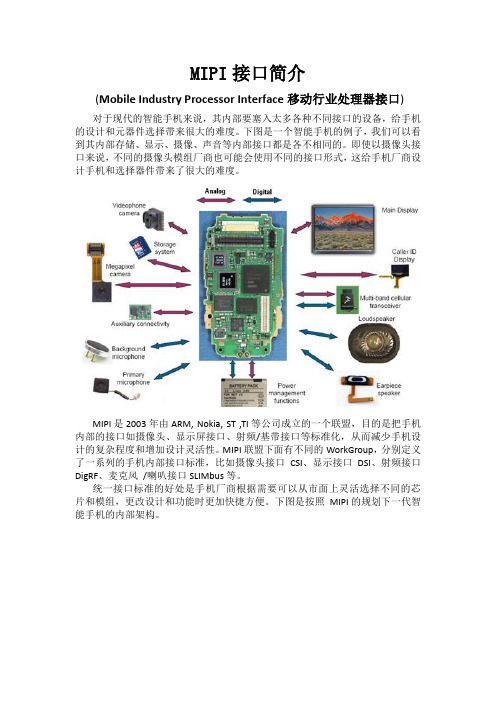
MIPI接口简介(Mobile Industry Processor Interface移动行业处理器接口)对于现代的智能手机来说,其内部要塞入太多各种不同接口的设备,给手机的设计和元器件选择带来很大的难度。
下图是一个智能手机的例子,我们可以看到其内部存储、显示、摄像、声音等内部接口都是各不相同的。
即使以摄像头接口来说,不同的摄像头模组厂商也可能会使用不同的接口形式,这给手机厂商设计手机和选择器件带来了很大的难度。
MIPI 是2003年由ARM, Nokia, ST ,TI等公司成立的一个联盟,目的是把手机内部的接口如摄像头、显示屏接口、射频/基带接口等标准化,从而减少手机设计的复杂程度和增加设计灵活性。
MIPI 联盟下面有不同的WorkGroup,分别定义了一系列的手机内部接口标准,比如摄像头接口CSI、显示接口DSI、射频接口DigRF、麦克风/喇叭接口SLIMbus等。
统一接口标准的好处是手机厂商根据需要可以从市面上灵活选择不同的芯片和模组,更改设计和功能时更加快捷方便。
下图是按照MIPI的规划下一代智能手机的内部架构。
MIPI是一个比较新的标准,其规范也在不断修改和改进,目前比较成熟的接口应用有DSI(显示接口)和CSI(摄像头接口)。
CSI/DSI分别是指其承载的是针对Camera或Display应用,都有复杂的协议结构。
以DSI为例,其协议层结构如下:CSI/DSI的物理层(Phy Layer)由专门的WorkGroup负责制定,其目前的标准是D-PHY。
D-PHY采用1对源同步的差分时钟和1~4对差分数据线来进行数据传输。
数据传输采用DDR方式,即在时钟的上下边沿都有数据传输。
D- PHY的物理层支持HS(High Speed)和LP(Low Power)两种工作模式。
HS模式下采用低压差分信号,功耗较大,但是可以传输很高的数据速率(数据速率为80M~1Gbps);LP模式下采用单端信号,数据速率很低(<10Mbps),但是相应的功耗也很低。
mipi 协议

mipi 协议MIPI协议。
MIPI(Mobile Industry Processor Interface)是一种针对移动设备的串行接口标准,旨在提高移动设备中的多媒体数据传输速度和可靠性。
MIPI联盟成立于2003年,由多家移动设备制造商和芯片厂商共同发起,包括英特尔、高通、三星、联发科等知名企业。
MIPI协议被广泛应用于智能手机、平板电脑、摄像头、显示屏等移动设备中,成为移动设备领域的重要标准之一。
MIPI协议的特点之一是高速传输。
随着移动设备中多媒体数据量的不断增加,对数据传输速度的要求也越来越高。
MIPI协议采用了一系列的高速串行接口标准,如MIPI D-PHY、C-PHY和M-PHY,以满足不同场景下的高速数据传输需求。
这些高速接口标准在保证数据传输速度的同时,也兼顾了功耗和信号完整性等方面的考量,使得移动设备在传输多媒体数据时能够保持高效、稳定的性能。
除了高速传输外,MIPI协议还注重低功耗。
移动设备作为便携式设备,对功耗的要求非常严格。
MIPI协议在设计时考虑了移动设备的功耗特性,通过采用低功耗的传输模式和优化协议设计,尽可能地降低了数据传输过程中的功耗消耗,从而延长了移动设备的续航时间。
此外,MIPI协议还支持灵活的接口配置。
移动设备中的传感器、摄像头、显示屏等组件种类繁多,不同组件对接口的要求也各不相同。
MIPI协议提供了丰富的接口配置选项,可以根据实际场景的需要选择合适的接口配置,以满足不同组件的接口需求,从而提高了移动设备的灵活性和可扩展性。
总的来说,MIPI协议作为一种面向移动设备的串行接口标准,具有高速传输、低功耗和灵活的接口配置等特点,已经成为移动设备领域的重要标准之一。
随着移动设备技术的不断发展和创新,MIPI协议也在不断完善和演进,为移动设备的性能提升和功能拓展提供了强有力的支持。
未来,随着5G、人工智能等新兴技术的广泛应用,MIPI协议将继续发挥重要作用,推动移动设备领域的发展。
MIPI__协议详细介绍

精选ppt
MIPI Development Team
2010-9-2
1
What is MIPI?
❖ MIPI stands for Mobile Industry Processor Interface ▪ MIPI Alliance is a collaboration of mobile industry leaders. ▪ Objective to promote open standards for interfaces to mobile
❖ Three main lane types
▪ Unidirectional Clock Lane ▪ Unidirectional Data Lane ▪ Bi-directional Data Lane
❖ Transmission Mode
▪ Low-Power signaling mode for control purpose:10MHz (max) ▪ High-Speed signaling mode for fast-data traffic:80Mbps ~ 1Gbps per Lane
application processors. ▪ Intends to speed deployment of new services to mobile users by
establishing Spec.
❖ Board Members in MIPI Alliance
▪ Intel, Motorola, Nokia, NXP,Samsung, ST, TI
2
What is MIPI?
❖ MIPI Alliance Specification for display
MIPIDSIEssentialMIPI协议详细介绍演示幻灯片

500Mbps/Lane, differential signaling 10Mbps, single ended signaling, lane 0 only
? Lane-Scalable, up to 4 data lanes
? Packet Based Data Transmission
– DSI Protocol has ECC, CRC capability -
TX: Distribute data to 1, 2, 3 or 4 lanes RX: Assembly data from 1, 2, 3 or 4 to one
byte stream
Physical Transmission / Reception Serializer / Deserializer
Display Refresh
Bus Interface
Display Driver
LCD Display
6
Command Mode Display
Host Processor
Image Update
Data
Bus Interface
Commands & Image Update
Data
Display Panel
containing DSI Transmitter
DSI Transmitter DataN+ DataN-
Bi-directional High Speed Data Links
Data0+ Data0-
N Data Lanes where N may be
1, 2, 3, or 4
Peripheral, e.g. a Display containing the DSI receiver
详解MIPI协议

前言 MIPI简介 MIPI联盟的MIPI DSI规范 MIPI名词解释 MIPI DSI分层结构 command和video模式 D-PHY Lane模组 Lane 全局架构 Lane电压和状态 DATA LANE操作模式 时钟LANE低功耗状态 高速数据传输 高速CLK传输 D-PHY总结 DSI CSI
MIPI (Mobile Industry Processor Interface) 是2003年由ARM, Nokia, ST ,TI等公司成立的一个联 盟,目的是把手机内部的接口如摄像头、显示屏接口、射频/基带接口等标准化,从而减少手机 设计的复杂程度和增加设计灵活性。
MIPI联盟下面有不同的WorkGroup,分别定义了一系列的手机内部接口标准,比如
Escape mode是数据Lane在LP状态下的一种特殊操作
在这种模式下,可以进入一些额外的功能:LPDT, ULPS, Trigger 数据Lane进入Escape mode模式通过LP-11→LP-10→LP-00→LP-01→LP-00 一旦进入Escape mode模式,发送端必须发送1个8-bit的命令来响应请求的动作 Escape mode 使用Spaced-One-Hot Encoding
超低功耗状态(Ultra-Low Power State)
这个状态下,lines处于空状态 (LP-00)
时钟Lane的超低功耗状态
时钟Lane通过LP-11→LP-10→LP-00进入ULPS状态 通过LP-10 → TWAKEUP →LP-11退出这种状态,最小TWAKEUP时间为1ms
高速数据传输
时序图如下
D-PHY总 结
Lane模组,Lane状态,Lane电压 Lane模组:LP-TX,LP-RX,HS-TX,HS-RX,LP-CD Lane状态:LP-00,LP-01,LP-10,LP-11,HS-0,HS-1 Line Levels(typical):LP:0-1.2V,HS:100-300mV(Swing:200mV)
MIPI协议详细介绍

MIPI协议详细介绍MIPI(Mobile Industry Processor Interface)是为移动设备设计的一种接口标准,由移动产业处理器接口工作组(Mobile Industry Processor Interface Working Group)所制定。
MIPI协议旨在提供移动设备所需的高性能、低功耗和低成本的接口解决方案。
MIPI协议的核心是一系列物理层和协议层规范。
在物理层上,MIPI 协议使用低压差分信号(Low Voltage Differential Signaling,LVDS)作为传输介质,以降低功耗和电磁干扰。
同时,MIPI协议还定义了一种叫做DSI(Display Serial Interface)的串行接口,用于连接显示器和处理器。
DSI接口支持传输图像、命令和控制信息,以及具有多种数据格式和分辨率的视频流。
在协议层上,MIPI协议提供了一系列协议规范,包括CSI(Camera Serial Interface)、RFFE(Radio Frequency Front-End)、SLIMbus (Serial Low-power Inter-chip Media Bus)、I3C(Improved Inter Integrated Circuit)等。
CSI接口用于连接摄像头和处理器,支持传输图像和控制信号。
RFFE接口用于连接射频模块和调制解调器芯片,支持传输射频频段切换和天线开关控制等功能。
SLIMbus接口用于连接多媒体芯片和音频处理器,支持音频、命令和控制信号的传输。
I3C接口是一种新兴的接口标准,旨在取代传统的I2C(Inter-Integrated Circuit)接口,提供更高的传输速率和更低的功耗。
除了物理层和协议层规范,MIPI协议还提供了一系列的软件驱动程序和API(Application Programming Interface),用于支持开发者在移动设备上使用MIPI接口的硬件功能。
MIPI协约详细介绍
DSI Layers
DCS spec DSI spec D-PHY spec
Outline
❖ D-PHY
▪ Introduction ▪ Lane Module, State and Line
levels ▪ Operating Modes
• Escape Mode
▪ System Power States ▪ Electrical Characteristics ▪ Summary
▪ Low-Power Transmitter (LP-TX) ▪ Low-Power Receiver (LP-RX) ▪ High-Speed Transmitter (HS-TX) ▪ High-Speed Receiver (HS-RX) ▪ Low-Power Contention Detector (LP-CD)
application processors. ▪ Intends to speed deployment of new services to mobile users by
establishing Spec.
❖ Board Members in MIPI Alliance
▪ Intel, Motorola, Nokia, NXP,Samsung, ST, TI
▪ DBI, DPI (Display Bus Interface, Display Pixel Interface)
• DBI:Parallel interfaces to display modules having display controllers and frame buffers.
• DPI:Parallel interfaces to display modules without on-panel display controller or frame buffer.
MIPI协议详细介绍1.
End-of-Transmission
H Toggles differential state immediately after last payload data bit
and keeps that state for a time THS-TRAIL
High-Speed Clock Transmission
A Clock Lane One or more Data Lanes
Three main lane types
Unidirectional Clock Lane Unidirectional Data Lane Bi-directional Data Lane
Transmission Mode
• Escape Mode
System Power States Electrical Characteristics Summary
Introduction for D-PHY
D-PHY describes a source synchronous, high speed, low power, low cost PHY A PHY configuration contains
Low-Power signaling mode for control purpose:10MHz (max) High-Speed signaling mode for fast-data traffic:80Mbps ~ 1Gbps per Lane
mipi协议

mipi协议1. 简介MIPI(Mobile Industry Processor Interface)协议是一种用于移动设备的串行接口协议,主要用于传输多媒体数据和控制信息。
它提供了一种高效、低功耗的通信方式,广泛应用于移动设备的摄像头、显示屏和其他传感器等模块之间的数据传输。
2. mipi协议的特点•高带宽:MIPI协议支持高速数据传输,可以满足高分辨率图像和视频的传输需求。
•低功耗:MIPI协议采用差分信号传输和低功耗时钟方案,有效降低了设备的功耗。
•灵活性:MIPI协议可以根据设备的需求进行配置,支持不同数据格式和传输速率的选择。
•可靠性:MIPI协议采用差错校验和流控制等机制,确保数据传输的可靠性。
•简化设计:MIPI协议提供了统一的接口标准,简化了设备的设计和开发过程。
3. mipi协议的应用3.1 摄像头模块MIPI协议被广泛应用于移动设备的摄像头模块。
摄像头模块通常由图像传感器、图像处理器和接口电路组成,其中接口电路使用MIPI协议进行数据传输。
使用MIPI协议可以实现高速、低功耗的图像数据传输,支持实时预览和拍照功能。
同时,MIPI协议还支持控制信息的传输,可以实现对摄像头模块的配置和控制。
3.2 显示屏模块MIPI协议也常用于移动设备的显示屏模块。
显示屏模块通常由显示驱动器、接口电路和显示屏组成,其中接口电路使用MIPI协议进行数据传输。
使用MIPI协议可以实现高分辨率、高帧率的图像显示,支持视频播放和游戏等应用场景。
同时,MIPI协议还支持触摸屏的数据传输,可以实现触摸输入功能。
3.3 其他传感器模块除了摄像头和显示屏模块,MIPI协议还被应用于其他传感器模块,如加速度计、陀螺仪和环境传感器等。
这些传感器模块可以通过MIPI协议与主控芯片进行数据通信,实现对环境、位置和姿态等信息的获取。
通过采集这些信息,可以为移动设备提供更多的功能和服务。
4. mipi协议的未来发展MIPI协议在移动设备领域的应用越来越广泛,随着移动设备的发展和需求的增加,MIPI协议也在不断演进和完善。
MIPI协议详细介绍上课讲义

▪ A transmitter shall send data LSB first, MSB last.
❖ D-PHY suited for mobile applications
Introduction for D-PHY
❖ D-PHY describes a source synchronous, high speed, low power, low cost PHY ❖ A PHY configuration contains
▪ A Clock Lane ▪ One or more Data Lanes
❖ Three main lane types
▪ Unidirectional Clock Lane
• Master:HS-TX, LP-TX • Slave:HS-RX, LP-RX
▪ Unidirectional Data Lane
• Master:HS-TX, LP-TX • Slave:HS-RX, LP-RX
▪ Bi-directional Data Lane ▪ Master, Slave:HS-TX, HS-RX,LP-TX, LP-RX, LP-CD
Universal Lane Module Architecture
Lane States and Line Levels
▪ The two LP-TX’s drive the two Lines of a Lane independently and single-ended.
▪ DSI:Display Serial Interface
MIPI协议详细介绍1
establishing Spec.
❖ Board Members in MIPI Alliance
▪ Intel, Motorola, Nokia, NXP,Samsung, ST, TI
▪ Bi-directional Data Lane ▪ Master, Slave:HS-TX, HS-RX,LP-TX, LP-RX, LP-CD
▪ DBI, DPI (Display Bus Interface, Display Pixel Interface)
• DBI:Parallel interfaces to display modules having display controllers and frame buffers.
• DPI:Parallel interfaces to display modules without on-panel display controller or frame buffer.
▪ DSI:Display Serial Interface
• A clock lane, One to four data lanes.
▪ CSI:Camera Serial Interface
Two Data Lane PHY Configuration
Lane Module
❖ PHY consists of D-PHY (Lane Module) ❖ D-PHY may contain
Introduction for D-PHY
❖ D-PHY describes a source synchronous, high speed, low power, low cost PHY ❖ A PHY configuration contains
mipi协议

mipi协议MIPI协议。
MIPI(Mobile Industry Processor Interface)是一种由移动产业处理器接口联盟(MIPI Alliance)制定的用于移动设备的接口标准。
MIPI协议旨在提供一种高效、低功耗、低成本的接口标准,以满足移动设备对于高速数据传输、低功耗和小尺寸的需求。
MIPI协议涉及到多个领域,包括显示、摄像头、传感器、存储、音频等,其标准化的接口设计使得不同供应商的芯片、模块和设备可以实现互操作性,从而降低了产品开发成本和市场推广时间。
MIPI协议的核心特点之一是其高速数据传输能力。
在移动设备中,高清视频、高分辨率图像等数据量庞大的应用越来越普及,对于数据传输速度提出了更高的要求。
MIPI协议采用了一系列的高速串行接口标准,如MIPI D-PHY、C-PHY和M-PHY,以支持从几百兆每秒到几十Gbps的数据传输速率。
这些接口标准不仅满足了当前移动设备的需求,还为未来更高分辨率、更高帧率的显示和摄像头应用提供了技术支持。
除了高速数据传输,MIPI协议还注重低功耗设计。
移动设备通常由电池供电,因此对于功耗的控制尤为重要。
MIPI协议在设计时考虑了功耗优化的需求,通过采用低电压差分信号传输、功耗管理协议等技术手段,实现了在高速数据传输的同时保持较低的功耗。
这使得移动设备可以在满足高性能需求的同时延长电池续航时间,提升用户体验。
另外,MIPI协议还关注了小尺寸、高集成度的设计。
移动设备通常对于空间的要求较高,因此需要在保证功能完整性的前提下尽量减小芯片和模块的尺寸。
MIPI协议通过采用高速串行接口、差分信号传输等技术,实现了对于接口线数的大幅度减少,从而减小了布线空间,降低了成本,并且提高了抗干扰能力。
总的来说,MIPI协议作为一种针对移动设备的接口标准,具有高速数据传输、低功耗设计、小尺寸高集成度等特点,为移动设备的设计和应用提供了技术支持。
随着移动设备对于高性能、低功耗的需求不断提升,MIPI协议也在不断演进,推出了新的接口标准和技术规范,以满足不断变化的市场需求。
MIPI DSI Essential(MIPI协议详细介绍)[优质ppt]
![MIPI DSI Essential(MIPI协议详细介绍)[优质ppt]](https://img.taocdn.com/s3/m/06070d54fab069dc51220112.png)
High Speed Unidirectional Clock Lane 0 -High Speed bidirectional Data Lane 1 -High Speed Unidirectional Data Lane 2 -High Speed Unidirectional Data Lane 3 -High Speed Unidirectional Data
Host Device, e.g. an Application Processor or Baseband Processor
containing DSI Transmitter
DSI Transmitter DataN+ DataN-
Bi-directional High Speed Data Links
MIPI DSI Interface Physical Architecture
■ 1 Clock Lane, unidirectional ■ 1 to 4 Data Lanes ■ Lane0 is bidirectional for LP data output transmission of the driver IC
Display Refresh
Bus Interface
Display r
LCD Display
6
Command Mode Display
Peripheral, e.g. a Display containing the DSI receiver
DSI Receiver DataN+ DataN-
mipi协议基础

mipi协议基础
MIPI(Mobile(Industry(Processor(Interface)协议是一种用于移动设备内部芯片之间通信的协议标准。
它主要用于连接移动设备中的摄像头、显示屏、传感器等组件与主处理器之间的高速数据传输。
MIPI(协议具有低功耗、高速、低成本等优点,因此被广泛应用于智能手机、平板电脑、相机等移动设备中。
MIPI(协议包括多个层次,其中最底层是物理层,用于定义电气信号和连接器;其次是数据链路层,用于处理数据传输和错误检测;然后是协议层,用于定义不同组件之间的通信协议。
MIPI(协议支持多种数据传输模式,如高速突发模式、低速突发模式和连续模式等,可以根据不同的应用场景选择合适的传输模式。
MIPI(协议是移动设备内部芯片之间通信的重要协议标准,它的出现大大提高了移动设备的性能和可靠性。
- 1、下载文档前请自行甄别文档内容的完整性,平台不提供额外的编辑、内容补充、找答案等附加服务。
- 2、"仅部分预览"的文档,不可在线预览部分如存在完整性等问题,可反馈申请退款(可完整预览的文档不适用该条件!)。
- 3、如文档侵犯您的权益,请联系客服反馈,我们会尽快为您处理(人工客服工作时间:9:00-18:30)。
MIPI Development Team 2010-9-2
What is MIPI?
❖ MIPI stands for Mobile Industry Processor Interface ▪ MIPI Alliance is a collaboration of mobile industry leaders. ▪ Objective to promote open standards for interfaces to mobile
❖ Three main lane types
▪ Unidirectional Clock Lane
• Master:HS-TX, LP-TX • Slave:HS-RX, LP-RX
▪ Unidirectional Data Lane
• Master:HS-TX, LP-TX • Slave:HS-RX, LP-RX
application processors. ▪ Intends to speed deployment of new services to mobile users by
establishing Spec.
❖ Board Members in MIPI Alliance
▪ Intel, Motorola, Nokia, NXP,Samsung, ST, TI
▪ DSI:Display Serial Interface
• A clock lane, One to four data lanes.
▪ CSI:Camera Serial Interface
Two Data Lane PHY Configuration
Lane Module
❖ PHY consists of D-PHY (Lane Module) ❖ D-PHY may contain
▪ DSI, CSI (Display Serial Interface, Camera Serial Interface)
• DSI specifies a high-speed serial interface between a host processor and display module.
DSI Layers
DCS spec DSI spec D-PHY spec
Outline
❖ D-PHY
▪ Introduction ▪ Lane Module, State and Line
levels ▪ Operating Modes
• Escape Mode
▪ System Power States ▪ al Characteristics ▪ Summary
▪ Bi-directional Data Lane ▪ Master, Slave:HS-TX, HS-RX,LP-TX, LP-RX, LP-CD
❖ Three main lane types
▪ Unidirectional Clock Lane ▪ Unidirectional Data Lane ▪ Bi-directional Data Lane
❖ Transmission Mode
▪ Low-Power signaling mode for control purpose:10MHz (max) ▪ High-Speed signaling mode for fast-data traffic:80Mbps ~ 1Gbps per Lane
▪ Low-Power Transmitter (LP-TX) ▪ Low-Power Receiver (LP-RX) ▪ High-Speed Transmitter (HS-TX) ▪ High-Speed Receiver (HS-RX) ▪ Low-Power Contention Detector (LP-CD)
▪ DBI, DPI (Display Bus Interface, Display Pixel Interface)
• DBI:Parallel interfaces to display modules having display controllers and frame buffers.
• DPI:Parallel interfaces to display modules without on-panel display controller or frame buffer.
Introduction for D-PHY
❖ D-PHY describes a source synchronous, high speed, low power, low cost PHY ❖ A PHY configuration contains
▪ A Clock Lane ▪ One or more Data Lanes
❖ D-PHY low-level protocol specifies a minimum data unit of one byte
▪ A transmitter shall send data LSB first, MSB last.
❖ D-PHY suited for mobile applications
What is MIPI?
❖ MIPI Alliance Specification for display
▪ DCS (Display Command Set)
• DCS is a standardized command set intended for command mode display modules.
• CSI specifies a high-speed serial interface between a host processor and camera module.
▪ D-PHY
• D-PHY provides the physical layer definition for DSI and CSI.
