可编程直流电源程序编程手册(SCPI版)V02
Keithley 36,00 Series SCPI 可编程直流电源说明书
36, 00 series SCPIProgrammable DC Power Supply© Copyright 2004 All Rights Reserved Ver2.0 /Sep 2005/DirectoryAbout your safety (3)Certification and Warranty (3)Chapter 1 Remote Operation Mode (5)Chapter 2 SCPI Order List (5)2.1 IEEE488.2 Common Order (5)2.2 SCPI Essential Order (5)2.3 Calibration Order (6)2.4 Output Order (6)2.5 Output Measure Order (6)Chapter 3 SCPI Condition Register (6)Chapter 4 SCPI Order Description (9)4.1 IEEE488.2 Common Order (9)4.2 SCPI Essential Order (10)4.3 Output Order (12)4.4 Input measurement order (13)About your safetyPease review the following safety precautions before operating our equipment.General informationThe following safety precautions should be observed before using this product and any associated instrumentations. Although some instruments and accessories would be used with non-hazardous voltages, there are situations where hazardous conditions may be present.This product is intended for use by qualified personnel who recognize shock hazards and are familiar with the safety precautions required to avoid possible injury. Read and follow all installation, operation, and maintenance information carefully before using the product. Refer to this manual for complete product specifications.If the product is used in a manner not specified, the protection provided by the product may be impaired.Before performing any maintenance, disconnect the line cord and all test cables.Protection from electric shockOperators of this instrument must be protected from electric shock at all times. The responsible body must ensure that operators are prevented access and/or insulated from every connection point. In some cases, connections must be exposed to potential human contact. Product operators in these circumstances must be trained to protect themselves from the risk of electric shock. If the circuit is capable of operating at or above 1000 volts, no conductive part of the circuit may be exposed.Definition of usersResponsible body is the individual or group responsible for the use and maintenance of equipment is operated within its specifications and operating limits, and for ensuring that operators are adequately trained.Operators use the product for its intended function. They must be trained in electrical safety procedures and proper use of the instrument. They must be protected from electric shock and contact with hazardous live circuits.Service is only to be performed by qualified service personnel.Safety symbols and termsConnect it to safety earth ground using the wire recommended in the usermanual.The symbol on an instrument indicates that the user should refer to the operatinginstructions located in the manual.High voltage dangerCertification and WarrantyCertificationWe certify that this product met its published specifications at time of shipment from the factory.WarrantyThis instrument product is warranted against defects in material and workmanship for a period of one year from date of delivery. During the warranty period we will, at its option, either repair or replace products which prove to be defective. For warranty service, with the exception of warranty options, this product must be returned to a service facility designated by us. Customer shall prepay shipping charges by (and shall pay all duty and taxes) for products returned to the supplier for warranty service. Except for products returned to customer from another country, supplier shall pay for return of products to customer.Limitation of WarrantyThe foregoing warranty shall not apply to defects resulting from improper or inadequate maintenance by the Customer, Customer-supplied software or interfacing, unauthorized modification or misuse, operation outside of the environmental specifications for the product, or improper site preparation and maintenance.Chapter 1 Remote Operation ModeE133 GPIB Communication CableThe DB9 interface connector on the rear panel of power supply is TTL voltage level; you can use the GPIB communication cable (E133) to connect the DB9 interface connector of the power supply, and then connect the GPIB interface of the E133 and computer with GPIB/IEEE 488 lineChapter 2 SCPI &RPPDQG List2.1 IEEE488.2 Common &RPPDQGV"*CLS""*ESE""*ESE?""*ESR?","*IDN?","*SRE","*SRE?","*STB?",2.2 SCPI Essential &RPPDQGVSYSTem:ERRor[:NEXT]?:VERSion?STATus:QUEStionable[:EVENt]?:CONDition?:ENABle <VALUE>:ENABle?2.3 Calibration &RPPDQGV CALibration :SECure [:STATe] {<ON|OFF>,<quoted code>} ]:STATe]? :VOLTage :LEVel {<level> } [:DATA] {<numeric value>} :CURRent :LEVel {<level> } [:DATA] {<numeric value>} :SAVe :INITital 2.4 Output &RPPDQGV OUTPut [:STATe] <b> [:STATe]? [SOURce:] VOLTage [:LEVel][:IMMediate][:AMPLitude] [:A MPLitude]? :PROTection[:LEVel] [:LEVel]? CURRent [:LEVel][:IMMediate][:AMPLitude] [:A MPLitude]?2.5 Output Measure &RPPDQGV MEASure [:SCALar] :VOLTage[:DC]? :CURRent[:DC]? :POWer[:DC]? Chapter 3 SCPI Condition RegisterYou can get the condition of power supply and read parameter from the operation register. The power supply can get the different state by 4 condition registers. These registers are status byte register, standard event register, quest condition register and operation status register. The status byte register stores the information of 3 other register. You can get each register’s meaning from the following table:B IT Signal Meaning 0 CV 23(5ation status register. The power supply is in constant voltage condition.1 CC The power supply is in constant current condition.0 1 OTUNRQuest condition registerOvertemperatureThe output of power supply is unregulated.0 2 34 57 OPCQYEDDEEXECMEPONStandard event status registerOperation of power supply is completed.Query error. Data of output array is missing.Device-dependent error. Data stored in register is missing or error occursin preliminary checkout.Execution error. Order parameter overflows or the condition is not right.Command error. Syntax or semantic error occurs when receivinginformation.Power on. It is 1when power supply is reset.3 4 5 6 7 QUESMAVESBMSSRQSOPERStatus byte registerIf a quest enable condition changes, QUES is 1.If the output array buffer storage is not empty, MAV is 1.If a standard event status enable register changes, ESB is 1.If a operation event enable register changes, OPER is 1.Structure of condition register V LV as following:Chapter 4 SCPI Order Description4.1 IEEE488.2 Common Commands*CLSThis order can clean the register as follows::Standard event status registerQuest condition registerOperation event registerStatus byte registerError codeOrder syntax:*CLSParameter:None*ESEThis order can set the parameter of standard event enable register. Setting parameter can determine which bit value of standard event register is 1 and the byte will enable ESB of status byte register is 1.Order syntax:*ESE <NRf>Parameter:0~255Reset value:Consult *PSC orderExample:*ESE 128Quest syntax:*ESE?Return parameter:<NR1>Reference order:*ESR? *PSC *STB?Bit determination of standard event enable registerBit position 7 6 5 4 3 2 1 0Bit Name PON Not used CME EXE DDE QYE Not used OPC Bit Weight 128 32 16 8 4PON Power-onCME Command error EXE Execution error DDE Device-dependent error QYE Query errorOPC Operation complete*ESR?This order can read the value of standard event status register. After executing this order, standard event status register is reset. Bit definition of standard event status register is as the same as the standard event status enable registerQuest syntax:*ESR?Parameter:NoneReturn parameter:<NR1>Reference order:*CLS *E SE *ESE?*OPC*IDN?This order can read information about power supply. The parameter it returns contains 4 segments divided by comma.Quest syntax:*IDN?Parameter:NoneReturn parameter:<AARD> segment descriptionITECH manufacturerXXXX product modeXXXXXX product serial numberVX.XX software version numberFor example:ITECH, IT6822, 6970001004, V1.54*SREThis order can set the parameter of status byte enable register. Setting parameter can determine which byte value of status byte register is 1 and the byte will enable RQS of status byte register is 1. Bit definition of status byte enable register is as the same as the status byte register.Order syntax:*SRE <NRf>Parameter:0~255Reset value:Consult *PSC orderExample:*SRE 128Quest syntax: *SRE?Return parameter:<NR1>Reference Order:*ESE *ESR? *PS C *STB?*STB?This order can read the data from status byte register. After executing this order, status byte register is reset.Quest syntax:*STB?Parameter:NoneReturn parameter:<NR1>Reference order:*CLS *ESE *ESRBit determination of standard event status enable register7 6 54 3 2 1 0PositionBitBit Name OPER RQS ESB no use QUES no use no use no use32864128BitValue4.2 SCPI Essential CommandsSYSTem:ERRor[:NEXT]?This order can get the error code and error information of the power supply.(0) No error(1) Too many numeric suffices in Command Spec(10) No Input Command to parse(14) Numeric suffix is invalid value(16) Invalid value in numeric or channel list, e.g. out of range(17) Invalid number of dimensions in a channel list(20) Parameter of type Numeric Value overflowed its storage(30) Wrong units for parameter(40) Wrong type of parameter(s)(50) Wrong number of parameters(60) Unmatched quotation mark (single/double) in parameters(65) Unmatched bracket(70) Command keywords were not recognized(80) No entry in list to retrieve (number list or channel list)(90) Too many dimensions in entry to be returned in parameters(101) Command Execution error(100) Too many command(110) Rxd error Parity(200) Error EEPROM data,Out Initial.(201) Error Calibration dataOrder syntax:SYST:ERR?Parameter:NoneReturn parameter:〈NR1〉,〈SRD〉SYSTem:VERSion?This order can query the software version.Order syntax:SYST:VERS?Parameter:NoneReturn parameter:<NR2>STATus:QUEStionable[:EVENt]?This order can read the parameter from quest event register. After executing , quest event register is reset.Quest syntax:STATus:QUEStionable[:EVENt]?Parameter:NoneReturn parameter:<NR1>Reference order:STATus:QUEStionable:ENABleBit determination of quest event registerBit Position 15 1413 12 11109 8 7 6 5 4 3 2 1 0 Bit name n.u n.u n.u n.u n.u n.u n.u n.u n.u n.u n.u n.u n.u n.u Un OT Bit Value 2 1STATus:QUEStionable:CONDition?This order can read the parameter from quest condition register. When a bit of quest condition changes, the bit value corresponding in quest event register is 1.Quest syntax:STATus:QUEStionable: CONDition?Parameter:NoneReturn parameter:<NR1>STATus:QUEStionable:ENABleThis order can set the parameter of quest event enable register. Setting parameter can determine which bit value of quest event register is 1 and the bit will enable QUES of status byte register is 1.Order syntax:STATus:QUEStionable:ENABle <NRf>Parameter:0~255Reset value:Consult *PSC orderExample:STATus:QUEStionable:ENABle 128Quest syntax:STATus:QUEStionable:ENABle?Return parameter:<NR1>Reference order:*PSCSTATus:OPERation:EVENt]?This order can read the parameter from operation event register. After executing this order, operation event register is reset.Quest syntax:STATus: OPERation [:EVENt]?Parameter:NoneReturn parameter:<NR1>Reference order:STATus: OPERation:ENABleBit determination of operation event enable registerBit Position 7 6 5 4 3 2 1 0Bit Name no use no use no use no use no use no use CC CVBit value 2 1 STATus:OPERation:CONDition?This order can read the parameter from the operation condition. When the parameter of operation condition register changes, the bit corresponding in operation event register is 1. Quest syntax:STATus: OPERation: CONDition?Parameter:NoneReturn parameter:<NR1>STATus:OPERation:ENABleThis order can set the parameter of operation even enable register. Setting parameter can determine which bit value of operation event register is 1 and the bit will enable OPER of status byte register is 1.Order syntax:STATus: OPERation:ENABle <NRf>Parameter:0~255Reset value:Consult *PSC orderExample:STATus: OPERation:ENABle 128Quest syntax:STATus: OPERation:ENABle?Return parameter:<NR1>Reference order:*PSC4.3 Output CommandsONPut[:STATe]This order can set power supply output on or off..Order syntax:ONPut[:STATe] <bool>Parameter:0|1|ON|OFF*RST value:OFFQuest syntax:ONPut:STATe?Return parameter:0|1[SOURce:]CURRent [:LEVel]This order can set current value of power supply.Order syntax:[SOURce:]CURRent [:LEVel] <NRf>Parameter:MIN TO MAX|MIN|MAXUnit:A mA*RST value: MINExample:CURR 3A,CURR 30mA,CURR MAX,CURR MIN Quest syntax:[SOURce:]CURRent [:LEVel]?Parameter:[MIN|MAX]Example:CURR?, CURR? MAX, CURR?MINReturn parameter:<NR2>[SOURce:]VOLTage[:LEVel]This order can set voltage value of power supply.Order syntax:[SOURce:]VOLTage[:LEVel] <NRf>Parameter:MIN TO MAX|MIN|MAXUnit:V mV kV*RST value:MAXQuest syntax:[SOURce:]VOLTage[:LEVel]?Parameter:[MIN|MAX]Return parameter:<NR2>[SOURce:]VOLTage:PROTection[:LEVel]This order can set voltage protection maximum level.Order syntax:[SOURce:] VOLTage:PROTection[:LEVel] <NR f> Parameter:MIN TO MAX|MIN|MAXUnit:V mV*RST value:MAXExample:VOLT:PROT 30V, VO LT PROT MAXQuest syntax:[SOURce:] VOLTage:PROTection[:LEVel]?Parameter:[MIN|MAX]Example:VOLT:PROT?, VO LT PROT? MAXReturn parameter:<NR2>4.4 Input measurement commands MEASure[:SCALar]:VOLTage[:DC]?This order can get the input voltage of power supply.Order syntax:MEASure[:SCALar]:VOLTage[:DC]?Parameter:NoneReturn parameter:〈NR2〉Return parameter unit:VExample:MEAS:VOLT?MEASure[:SCALar]:CURRent[:DC]?This order can get the input current of power supply.Order syntax:MEASure[:SCALar]:CURRent[:DC]?Parameter:NoneReturn parameter:〈NR2〉Return parameter unit:AExample:MEAS:CURR?MEASure[:SCALar]:POWer[:DC]?This order can get the input power of the power supply.Order syntax:MEASure[:SCALar]:POWer?Parameter:NoneReturn parameter:〈NR2〉Return parameter unit:WExample:MEAS:POW?Calibration orderCALibration:SECure:[STATe]Set protection mode enable or disable when calibrating the power supply.Order syntax:CALibration:SECure:[STATe ]{ON|OFF>,[<password>]}Parameter:0|1|ON|OFF, ‘5811Example:CAL:SEC 1, ‘5811; CAL:SEC OFFQuest syntax:CALibration:SECure:STATe?Parameter:NoneCALibration:VOLTage:LEVelThis order can set voltage calibration point. P1、P2、P3、P4 must be calibrated orderly. Order syntax:CALibration:VOLTage:LEVel <point>Parameter:P1|P2CALibration:VOLTage [:DATA] {<numeric value>}Return actual output voltage value of calibration point.Order syntax:CALibration:VOLTage [:DATA] <NRf>Parameter:<NRf>Example:CAL:VOLT 30.0002VCALibration:CURRent:LEVelThis order can set current calibration point. P1、P2、P3、P4 must be calibrated orderly. Order syntax:CALibration:CURRent:LEVel <point>Parameter:P1|P2CALibration:CURRent [:DATA] {<numeric value>}Return actual output current value to calibration point.Order syntax:CALibration:CURRent [:DATA] <NRf>Parameter:<NRf>Example:CAL:VOLT 3.0002A。
SCPI通信协议 直流可编程电子负载 IT8500系列说明书

SCPI通信协议直流可编程电子负载IT8500系列版权归属于艾德克斯电子(南京)有限公司本使用手册适用于下列机型的通信型号IT8511/IT8612/IT8512B/IT8513B/IT8513CIT8514B/IT8514C/IT8515B/IT8515C/IT8516B/IT8516CIT8518B/IT8518C/IT8518E/IT8518F张先生:189********固话:0755-********传真:0755-36692885目录第一章:通讯模块介绍 ................................................................. 4第二章 SCPI命令表 .....................................................................52.1 IEEE488.2 共同命令 ................................................ 5 2.2 SCPI 必备命令 .................................................... 5 2.3 标定命令 .......................................................... 6 2.4 输出设定命令 ....................................................... 6 2.5 量测命令 .......................................................... 8 2.6 接口配置命令 ....................................................... 8 2.7 触发命令 . (8)第三章 SCPI状态寄存器 (9)第四章 SCPI命令描述 .................................................................11 4.1 IEEE488.2 共同命令 ................................................ 11 4.2 SCPI 必备命令 ..................................................... 154.3 输出设定命令 ....................................................... 18 4.4 量测命令 ........................................................... 24 4.5 接口配置命令 ....................................................... 254.6 触发命令 ........................................................... 254.7 必备命令........................................................... 264.8 标定命令 ........................................................... 272张先生:189********固话:0755-********传真:0755-********通告本手册的内容如有更改,恕不另行通知。
可编程直流电源说明书

(操作手册)手册使用事项声明本手册内容如有变更,恕不另行通知。
使用产品之前请仔细阅读本手册,阅后请将手册置于产品附近,以便需要的时候取阅,产品位置变动时,请附带该产品手册。
本手册虽经认真审阅,但纰漏在所难免,如发现错误及不明之处,请联系公司客服或仪器代理商。
故本公司将不对手册内容错误或使用本手册所造成的直接、间接、突发性或继续性的损害负任何责任。
版权声明:版权归本公司所有,未经许可不得翻印、抄袭、修改本用户手册。
校验及校正声明特别声明,本手册所列的电源设备完全符合本公司一般型录上所标称的规范和特性。
本电源在出厂前已经通过本公司的厂内校验。
校验的程序和步骤是符合电子检验中心的规范和标准。
品质保证1、本公司保证所生产制造的产品均经过严格的品质确认,出厂产品质量保证期为十二个月,在此期间出现的产品制造缺陷或故障,均免费给予修复。
2、对于用户自行更改线路、功能而造成的故障或超过质量保证期的产品,视实际状况收取维修成本费,对于不可抗力造成的故障及损毁,发生故障,例如地震、水灾、暴动、或火灾等非人力可控制的因素,本公司不予免费保修服务。
安全说明在整个操作、维护以及修理本产品的过程中必须遵循本节以及手册中的安全预防措施。
不遵循这些安全预防措施,厂家声明不对用户违反此类要求的操作负责任。
安全符号1、电气符号、安全标识以及警告标识定义符号描述符号描述AC 交流电禁止DC 直流电接通电源AC/DC 交流/直流电断开电源N N 中性导体表示用同一个操作件使电源接通/断开的开关。
通常使用的按键有两个稳定位置。
PE 保护导体接地高温:表示此处温度高于人体可接受范围,勿任意接触以免人员伤害注意安全:为避免人员伤害、或对仪器的损害,操作者必须参考手册中的说明当心触电该标识提示有风险,如果不能遵照操作说明使用,可能会造成人身伤害,在未理解说明指示前,请不要进行操作。
该标识提示有风险,如果不能遵照操作说明使用,可能导致人员伤亡,此标记唤起您对程序、惯例、条件等的注意2、安全简要在对本仪器操作或维护期间必须注意下列一般性安全预防措施,若顾客无法遵守这些预防措施或本手册中任何明确的警告而造成人员伤害或机器损坏,我们将不负任何赔偿责任。
IT6800系列 直流可编程电源 用户使用手册说明书

版权归属于艾德克斯电子(南京)有限公司Ver2.0/Jan, 2010/ IT6800-603用户使用手册直流可编程电源本使用手册适用于下列机型型号 IT6821 IT6822 IT6823 IT6831 IT6832 IT6833 IT6834IT6800系列目录前面板介绍 (5)功能按键说明 (5)菜单操作 (5)VFD指示灯功能描述 (6)背面板介绍 (6)第一章 快速入门 (7)1.1 预先检查 (7)1. 验货 (7)2.接上电源线并打开电源 (7)3.系统自检 (7)1.2 输出检查 (8)输出电压检查 (8)输出电流检查 (8)1.3 如果电源供应器不能启动 (8)1.4 电源把柄的调节方法 (9)1.5 电源上架操作 (10)第二章 技术规格 (11)2.1 主要技术参数 (11)2.2 补充特性 (11)第三章 面板操作 (13)3.1 前面板操作介绍 (13)3.2 定电压设置操作 (14)3.3 定电流设置操作 (14)3.4 存取操作 (15)3.5 菜单操作 (15)电压上限设置(>MAX VOLT) (15)电源上电后输出状态设定(>INIT OUT) (15)电源上电后输出电压设定(>INIT VOLT) (15)键盘发声设置(>KEY SOUND) (15)通讯波特率设置(>BAUD RATE) (16)通讯地址设置(>ADDR) (16)功能按键密码设置(>KEY LOCK) (16)第四章 远端操作模式 (17)4.1通讯模块简介 (17)4.2 电源与PC间的通讯 (18)2安全请勿自行在仪器上安装替代零件,或执行任何未经授权的修改。
请将仪器送到本公司的维修部门进行维修,以确保其安全特性。
请参考本手册中特定的警告或注意事项信息,以避免造成人体伤害或仪器损坏。
仪器内部并无操作人员可维修的部件,需维修服务,请联络受过训练的维修人员。
UNI-T UDP5300 系列电源通信协议 (SCPI MODBUS) 使用说明书
UNI-T使用说明书UDP5300系列电源通信协议(SCPI&MODBUS)-V1.02020年8月UNI-T TECHNOLOGY(China) Co.,LtUNI-T 保证和声明版权2019 优利德科技(中国)股份有限公司商标信息UNI-T是优利德科技(中国)股份有限公司的注册商标。
声明●本公司产品受中国及其它国家和地区的专利(包括已取得的和正在申请的专利)保护。
●本公司保留改变规格及价格的权利。
●本手册提供的信息取代以往出版的所有资料。
●本手册提供的信息如有变更,恕不另行通知。
●对于本手册可能包含的错误,或因手册所提供的信息及演绎的功能以及因使用本手册而导致的任何偶然或继发的损失,UNI-T概不负责。
●未经UNI-T事先书面许可,不得影印、复制或改编本手册的任何部分。
产品认证UNI-T认证本产品符合中国国家产品标准和行业产品标准及ISO9001:2015标准和ISO14001:2015标准,并进一步认证本产品符合其它国际标准组织成员的相关标准。
联系我们如您在使用此产品或本手册的过程中有任何问题或需求,可与UNI-T联系:电子邮箱:网址:1.1 SCPI命令概述UDP5300系列可编程直流电源,支持SCPI通信协议。
SCPI 是一种用于可编程仪表的标准命令,它定义了一套通讯时的命令规则。
用于UDP5300系列电源的命令分成两大类:基本命令(IEEE-488.2公用命令集)和UDP5300系列指定的命令集。
SCPI命令均采用命令树的层次结构排列。
每个命令包含许多字符串(助记符),层与层之间以冒号分隔(:)。
在命令树顶端的命令称为“根命令”或简称“根”。
访问下次命令,必须指定一条路径。
命令树的结构如下:图中,AA表示根路径;BB,CC,DD表示根路径下的直接子路径。
EE,FF,GG 表示是子路径BB下的子路径。
HH,JJ表示是子路径DD下的子路径。
命令说明:1)[:]AA:CC 表示当前根路径为AA,访问AA下的CC。
高精度可编程直流电源原理(一)
高精度可编程直流电源原理(一)高精度可编程直流电源介绍•高精度可编程直流电源是一种可以提供稳定、可调的直流电压和电流输出的电子设备。
•它具有高精度、可编程控制、多功能等特点,广泛应用于科研实验、电子设备测试、通信设备等领域。
基本原理1.输入电源:高精度可编程直流电源通常通过交流电源(AC)输入,经过整流和滤波电路将交流电转换为直流电。
2.电压调节:通过电压调节电路,可以控制输出电压的大小。
常见的调节方式有可变电阻调节、PWM调节等。
3.电流控制:电流控制电路通过反馈机制,监测输出电流并进行调整,以达到设定的电流值。
4.保护功能:高精度可编程直流电源通常具有过压、过流、过热等保护功能,确保设备及用户的安全。
精度与分辨率1.精度:高精度可编程直流电源的精度指输出电压或电流与设定值之间的偏差程度。
精度一般用百分比或以千分比表示。
2.分辨率:分辨率指调节输出电压或电流时,能够调节的最小单位。
较高的分辨率可以提供更准确和精确的控制。
可编程性与控制方式1.可编程性:高精度可编程直流电源可以通过不同的编程方式来设定输出电压和电流的数值。
常见的编程方式有面板按键编程、PC端软件编程、通讯协议编程等。
2.控制方式:高精度可编程直流电源的控制方式包括恒压模式和恒流模式。
在恒压模式下,输出电压稳定,而在恒流模式下,输出电流稳定。
功能特点1.输出模式:高精度可编程直流电源通常支持恒压模式和恒流模式两种输出模式,可根据需求进行切换。
2.过载保护:在实际使用中,电流可能会超过设定的最大值,高精度可编程直流电源通常具有过载保护功能,确保设备安全。
3.调节速度:高精度可编程直流电源的调节速度对于某些应用场景很重要,较快的调节速度可以提高工作效率。
4.反馈机制:通过反馈电路监测输出情况,并进行调整,以保持输出的稳定性和精度。
应用领域1.科研实验:高精度可编程直流电源在科学研究中的应用广泛,例如电化学实验、材料研究等。
2.电子设备测试:在电子设备的生产和测试过程中,高精度可编程直流电源可以提供稳定的电源供应。
艾默生 24448 系列可编程交流电源用户手册说明书

用户手册Rev1.0系列可编程交流电源用户手册版权所有翻印必究如有变更恕不通知目录1.联系我们 (25)2.保修与安全信息 (26)2.1有限售后保证 (26)2.2安全 (28)2.3安全规则 (28)2.4安全标识的含义 (28)2.5安全信息 (29)2.6安全注意事项 (31)3.产品概述 (39)3.1一般说明 (39)3.2产品特点 (40)13.3功能方框图 (41)3.4操作描述 (42)3.5测量与数据 (42)3.6附件 (42)3.7远程控制扩展接口 (43)4.技术规格 (45)4.1产品型号 (45)4.2技术规格 (46)4.3外形尺寸 (55)4.4输出电压与电流曲线 (56)4.5输出电压与频率曲线 (58)4.6输出电压THD与功率 (61)24.7输出电压THD与频率曲线 (62)4.8输出电压频率与功率曲线 (62)4.9输出电压精度与频率 (65)4.10谐波幅值误差与谐波次数关系曲线 (66)4.11直流模式输出功率曲线 (69)4.12输入电压与输出功率降额曲线 (71)4.13输出过流保护延迟曲线 (71)4.14环境 (72)4.15输出降额与环境温度 (73)4.15.1音频噪声与环境温度 (74)4.15.2音频噪声与输出功率 (75)4.15.3音频噪声与输出频率 (76)34.16安规及认证 (77)5.开箱和安装 (78)5.1检查 (78)5.2搬运说明 (79)5.3检查交流输入 (80)5.4交流输入连接 (80)5.5接地要求 (83)5.5.1机壳接地 (83)5.5.2输出中点接地 (84)5.6输入开关 (85)5.7桌面使用 (86)5.8通风 (87)45.9噪声水平 (87)5.10液体防护 (88)5.11清洁 (88)5.12负载连接 (89)5.12.1输出接线和建议线径 (89)5.12.2三相Y形负载连接 (90)5.12.3三相Δ形负载连接 (92)5.12.4单相/直流负载连接 (94)5.13远端补偿连接 (96)5.14异常状况处理 (96)6.前操作面板 (97)6.1前面板布局 (97)56.2开机/关机/复位按钮及操作 (99)6.2.1待机状态指示 (99)6.2.2开机状态指示 (101)6.2.3故障状态指示 (102)6.3输出使能按钮 (103)6.3.1输出状态指示 (103)6.3.2输出时序 (104)6.3.3输出响应时间 (104)6.4菜单键 (105)6.4.1测量键(MEAS) (105)6.4.2编程键(PROG) (106)6.4.3配置键(CONF) (107)66.4.4系统键(UTIL) (108)6.5功能键 (109)6.5.1方向键 (110)6.5.2返回键 (110)6.5.3确认键(OK) (110)6.5.4翻页键 (110)6.6数字键 (111)6.6.1数字键 (111)6.6.2取消键 (111)6.6.3消除按键 (111)6.6.4回车键 (112)6.7飞梭 (112)76.7.1电压飞梭旋钮 (112)6.7.2频率飞梭旋钮 (112)7.显示屏 (113)7.1测量 (113)7.1.1测量页面 (120)7.1.2电压页面 (121)7.1.3电流页面 (124)7.1.4功率页面 (127)7.1.5谐波页面 (128)7.2配置 (131)7.2.1稳态参数页面 (131)7.2.2输出设置页面 (137)87.2.3保护设置页面 (138)7.2.4波形数据页面 (139)7.2.5校准页面 (142)7.3编程 (149)7.3.1暂态List页面 (150)7.3.2暂态Pulse页面 (155)7.3.3暂态Step页面 (159)7.3.4谐波页面 (165)7.3.5间谐波页面 (167)7.3.6编程数据页面 (171)7.3.7触发设置页面 (178)7.4系统 (180)97.4.1通讯设置页面 (180)7.4.2参数存取页面 (184)7.4.3扩展设置页面 (186)7.4.4本地设置页面 (187)7.4.5系统信息页面 (189)8.后面板 (190)8.1输入连接器 (190)8.2输出连接器 (191)8.2.1电缆尺寸 (192)8.2.2连接步骤 (193)8.3接地端子 (193)8.4线缆固定 (194)108.5远端补偿接口 (194)8.6多功能接口 (195)8.6.1触发终端 (196)9.远端控制 (199)9.1概述 (199)9.2通信规约 (199)9.2.1常用符号 (199)9.2.2参数格式 (201)9.2.3SCPI指令介绍 (202)9.2.4执行次序 (206)9.3共同指令 (206)9.4仪器指令 (209)119.4.1测量指令 (209)9.4.2编程指令 (230)9.4.3设置指令 (260)9.4.4系统指令 (302)9.4.5状态指令 (306)9.4.6输出指令 (309)9.4.7触发指令 (310)9.4.8初始化指令 (314)9.5SCPI指令树 (316)10.附录1-内置谐波示例 (324)11.附录2-编程示例 (332)11.1电压暂降示例 (332)1211.2电压短时中断示例 (339)11.3短期供电电压变化试验示例 (341)13图1断开交流电源后的交流输入滤波器剩余电压检查示意图 (35)图2PAC系列功能框图 (41)图3PAC0115~PAC0315外型尺寸图 (55)图4恒功率曲线图 (57)图5PAC0115三相模式下单相输出电压与输出功率的关系 (59)图6PAC0215三相模式下单相输出电压与输出功率的关系 (60)图7PAC0315三相模式下单相输出电压与输出功率的关系 (61)图8输出频率与输出电压THD百分比关系 (62)图9PAC0315恒功率条件下输出电压与输出电流的关系 (63)图10输出频率与输出功率关系15 u-70 u (64)图11输出频率与输出功率关系70 u-5000 u (65)图1250/60 u谐波幅值误差与次数的关系 (67)14图13400 u谐波幅值误差与频次关系 (68)图14直流恒压模式下输出电压与输出电流关系 (70)图15降额曲线—输入电压 (71)图16过流保护延迟曲线 (72)图17温度与输出功率曲线 (74)图18环境温度与噪声曲线 (75)图19输出功率与噪声曲线 (76)图20PAC包装拆解示意图 (79)图21后面板接口说明图 (82)图22输出中点接地示意图 (85)图23输入开关图 (86)图24Y形负载连接示意图 (91)15图25Δ形负载连接示意图 (93)图26单相/直流负接线示意图 (95)图27远端补偿连接示意图 (96)图28功能及区域分划图 (98)图29输入开关-开机状态 (100)图30开机/关机/复位按钮-待机状态 (100)图31开机过程示意图 (101)图32开机结束示意图 (102)图33接通状态示意图 (103)图34电源输出时序图 (104)图35测量首页面 (106)图36编程首页面 (107)16图37配置首页面 (108)图38设置首页面 (109)图39页面区域功能分布示图 (114)图40测量-测量页面 (120)图41测量-电压页面 (121)图42电压波形信息图 (122)图43测量-电流页面 (124)图44电流波形信息图 (125)图45测量-功率页面 (127)图46测量-谐波页面 (129)图47稳态参数页面 (131)图48三角波对称度波形示例 (134)17图49交流分量斜率示例 (135)图50输出摆率示例 (136)图51输出设置页面 (137)图52保护设置页面 (139)图53波形数据页面 (140)图54外部存储页面 (141)图55外部波形存储页面 (142)图56解锁校准页面 (143)图57校准页面 (144)图58校准电压零偏接线示意图 (145)图59校准电压增益接线示意图 (147)图60暂态List页面 (150)18图61暂态List页面-更多设置 (151)图62暂态Pulse-基波页面 (155)图63暂态Pulse-脉冲页面 (156)图64暂态Pulse页面-更多设置 (157)图65暂态Step-交流页面 (160)图66暂态Step-直流页面 (161)图67暂态Step-频率页面 (162)图68谐波页面 (165)图69谐波存储界面 (167)图70间谐波页面 (168)图71间谐波页面-更多设置 (169)图72编程数据-暂态List数据列表 (172)19图73编程数据-暂态Pulse数据列表 (173)图74编程数据-暂态Step数据列表 (174)图75编程数据-暂态谐波数据列表 (175)图76编程数据-间谐波数据列表 (176)图77编程数据-外部存储-暂态 (177)图78触发设置页面 (178)图79通讯设置-RS232 (180)图80通讯设置-LAN (182)图81通讯设置-USB (183)图82参数存取页面 (184)图83扩展设置页面 (187)图84本地设置页面 (188)20图85系统信息页面 (189)图86补偿线缆连接顺序及色标 (195)图87触发终端前面板功能划分 (196)图88触发终端后面板功能划分 (198)图89指令结构 (203)21表1附件名称及数量表 (43)表2PAC系列型号表 (45)表3PAC系列尺寸重量表 (46)表4技术规格总揽表 (47)表5PAC工作环境表 (73)表6测量级页面快捷键功能 (115)表7电源故障信息 (116)表8电源状态信息表 (116)表9数据栏数值颜色含义 (118)表10电压波形信息计算方法表 (122)表11电流波形信息计算方法表 (126)表12功率信息计算方法表 (127)22表13谐波显示次数与频率的关系 (129)表14谐波显示数据范围表 (130)表15波形类型与频率范围关系表 (132)表16交流(V)与工作频率范围关系表 (152)表17有效值模式说明表 (154)表18交流(V)与工作频率范围关系表 (158)表19有效值模式说明表 (159)表20有效值模式说明表 (164)表21工作频率与可设谐波次数的关系 (166)表22输出连接器连接数据限值表 (192)表23编程指令的数字格式 (201)表24可用的共同指令 (206)23表25可用的SCPI子系统指令 (209)表26触发执行指令发送方式 (233)表27谐波编程电源设置 (254)表28电源输出频率与可设谐波次数间的关系 (254)表29电源输出频率与交流电压给定范围间的关系 (266)241.联系我们地址:中国·陕西·西安新型工业园区信息大道12号邮编:710119电话:+86(029)856918708569187185691872传真:+86(029)85692080网址:邮箱:******************252.保修与安全信息2.1有限售后保证西安爱科赛博电气股份有限公司对所制造及销售的PAC产品自交货之日起一年内,保证正常使用情况下产生故障或损坏,负责免费维修。
5 第5章 虚拟仪器软件标准--02

(2)CONFigure:配置命令
CONFigure命令的一般形式为: CONFigure:< function > < parameters > [,< source list > ] 该命令完成仪器配置,其参数意义及用法与 MEASure命令一致。例如,对于数字万用表, 该命令用指定参数设置数字万用表。
信号路由选择 测量功能 格式化 数据总线
触发 信号路由选择
存储器 格式化 数据总线
信号产生
5.1.3 SCPI命令句法
SCPI程控命令标准由3部分内容组成:
第一部分“语法和样式”,描述SCPI命令的产 生规则以及基本的命令结构; 第二部分“命令标记”,主要给出SCPI要求或 可供选择的命令; 第三部分“数据交换格式”描述了一种数据采 集的标准表示方法,用于实现仪器与仪器之间 及其他应用场合中的数据交换。
5.1.4 常用SCPI命令简介
1. 常用仪器公用命令 (1)*IDN?仪器标识查询命令。每台VXI仪器都指 定了一个仪器标识代码。如对 HP1411B 模块,该 命令实际返回标识码Hewlett Packard,E1411B, 0,G.06.03。 ( 2 ) RST 复位命令。复位仪器到初始上电状态。在 仪器工作过程中,当发生程序出错或其他死机情况 时,经常需要复位仪器。一般情况下先用命令*CLS 清仪器,然后再复位。
测试应用软件 测试编程环境 仪器软面板
仪器驱动器 I/O 接口驱动软件(VISA) GPIB 其他
VXI
虚拟仪器的软件体系结构
5.2.1 VISA的结构与特点
VISA的结构模型为金字塔结构 ,如图
Hale Waihona Puke VISA的特点(1)VISA的I/O控制功能适用于各种类型仪器,包括 VXI 仪器、 GPIB 仪器和 RS-232C 接口仪器等,既可 用于VXI消息基器件,也可用于VXI寄存器基器件。
科迪欧 SPD3000X 系列可编程线性直流电源 数据手册说明书

特性与优点
三路高精度电源独立可控输出:32V/3.2A×2, 可切换 2.5V/3.3V/5V/3.2A×1,总功率 220W 最高 5 位电压和 4 位电流显示,最小分辨率 为 1mV、1mA 支持面板定时输出功能 4.3 英寸的 TFT-LCD 液晶显示屏,480 *272 高分辨率 三种输出模式:独立,串联和并联连接;支持 定时输出,波形显示和 SCPI 远程命令 100V/120V/220V/230V 兼容的设计,以满足 不同电网的需求 智能温控风扇,有效降低噪音 清晰的图形化界面,具有波形显示功能 内部 5 组系统参数保存/调取,支持数据存储 空间扩展 提供 EasyPower 上位机软件,支持 SCPI 程 控命令集和 LabView 驱动包,满足远程控制 和通信需求
输出电压 (2.5 / 3.3 / 5V) ±8%
CH3
线性调整率 ≤ 0.01%+3mV 负载调整率 ≤ 0.01%+3mV
纹波和噪声 ≤ 1mVrms(5Hz ~ 1MHz)
锁键
有
保存/调用
5组
最大输出功率
220W
4
SPD3000X 系列可编程线性直流电源
输入电源
AC 100V / 120V / 220V / 230V ±10% 50/60Hz
联系我们 深圳市鼎阳科技股份有限公司 全国免费服务热线:400-878-0807 网址:
声明 是深圳市鼎阳科技股份有限公
司的注册商标,事先未经过允许,不得以任何形式 或通过任何方式复制本手册中的任何内容。 本资料中的信息代替原先的此前所有版本。技术数 据如有变更,恕不另行通告。
产品代码 SPD3303X-E
SPD3303X
SPD3000X 系列可编程线性直流电源
欧姆龙CP系列编程手册00002
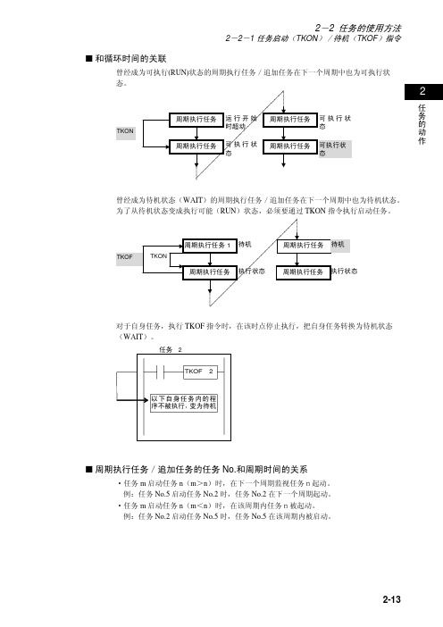
2-2-1 任务启动(TKON )/待机(TKOF )指令任务的动作■ 和循环时间的关联曾经成为可执行(RUN)状态的周期执行任务/追加任务在下一个周期中也为可执行状态。
TKON曾经成为待机状态(WAIT )的周期执行任务/追加任务在下一个周期中也为待机状态。
为了从待机状态变成执行可能(RUN )状态,必须要通过TKON 指令执行启动任务。
对于自身任务,执行TKOF 指令时,在该时点停止执行,把自身任务转换为待机状态(WAIT )。
■ 周期执行任务/追加任务的任务No.和周期时间的关系·任务m 启动任务n (m >n )时,在下一个周期监视任务n起动。
例:任务No.5启动任务No.2时,任务No.2在下一个周期起动。
·任务m 启动任务n (m <n )时,在该周期内任务n被起动。
例:任务No.2启动任务No.5时,任务No.5在该周期内被启动。
2-2-1 任务启动(TKON)/待机(TKOF)指令任务的动作·任务m使任务n(m>n)为待机时,在下一周期任务n为待机(任务n在该周期内已经执行完)。
例:任务No.5使任务No.2为待机时,任务No.2下一个周期为待机。
·任务m使任务n(m<n)为待机时,在该周期内任务n为待机。
例:任务No.2要使任务No.5为待机时,任务No.5在该周期为待机。
■任务和I/O内存的关系·在变址寄存器(IR)以及数据寄存器(DR)中有2种使用方法。
①按各个任务分别(单独)使用的方法②各任务共同使用的方法在①的方法中,在周期执行任务1中使用的IR0和在周期执行任务2中使用的IR0不相同。
在②的方法中,在周期执行任务1中使用的IR0和周期执行任务2中使用的IR0为相同。
对于变址寄存器(IR)以及数据寄存器(DR)采用①的方法还是采用②的方法由CX-Programmer进行设定。
·其它区域各任务共同使用。
比如对于在周期执行任务1中使用的接点10.00和周期执行任务2中使用的接点10.00是指同一个接点。
PRD 系列可编程直流电源用户手册说明书
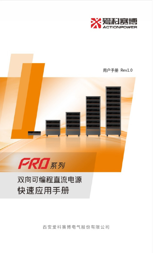
用户手册 Rev1.01 前言感谢您购买了西安爱科赛博电气股份有限公司的PRD 系列可编程直流电源。
本手册介绍了PRD的使用方法。
2安全信息在使用和操作设备前,为确保性能最佳,并避免出现危险,请认真阅读本手册不得违规操作。
3前面板PRD设计了一体化面板,将物理按键与融入面板之中,未上电状态下面板与设备完美融合。
将操作功能按使用频度、操作习惯原则分配,按键功能置于左下方,旋转功能置于右上方,极大加快了操作效率,提高了准确度,操作功能的区分同时兼顾了左手惯用及右手惯用者,使每个操作者都能得心应手。
前面板功能分区如图1所示,包括显示屏幕、厂家LOGO、外部存储接口、电源/复位按键、输出按键、左飞梭旋钮、左飞梭按键、右飞梭旋钮以及右飞梭按键。
厂家电源/图1前面板功能分区图4后面板后面板包括Anyport接口、Energy matrix接口、LAN 接口、USB接口、选配接口、SENSE接口、输出铜排正极、输出铜排负极、三相输入连接器、PE接线器、交流端断路器,如图2所示。
Anyport接口LANUSB连接器图2后面板功能分区图5源载功能PRD集电源与负载于一体,两种模式之间可无缝切换。
电源模式:PRD工作于电源模式,可为外部直流负载提供直流电压。
在此模式下,直流端是输出端。
负载模式:PRD工作于负载模式,可从外部直流源获取能量。
在此模式下,直流端是输入端。
源和负载可实现自动切换,外接负载时,工作于电源模式;外接直流源时:当PRD直流端电压大于外接直流源电压时,工作于电源模式;当PRD直流端电压小于外接直流源电压时,工作于负载模式。
例:PRD电压设置500V,外接用户设备电压设置300V,PRD此时工作在电源模式,将PRD电压设置改为200V时,PRD此时工作在负载模式。
6编程功能PRD设计了关于幅值与时间编程的功能,单功能支持多达200序列的编程,可选择多种模式来编辑电压和电流波形,通过灵活的配置参数,可编辑出所需的波形,整个编程策略均为从稳态开始,结束后再回到稳态。
Agilent E363xA系列可编程直流电源数据手册说明书

AgilentE363xA Series Programmable DC Power SuppliesData SheetReliable Power,Repeatable Results• Single and triple output• 80 W to 200 W output power • Dual range output(except E3631A)• Low noise and excellentregulation• Remote sensing(except E3631A)• Front and rear outputterminals(E3633A/34A only)• GPIB and RS-232 standard• Save and recall functions• Overvoltage protection,Overcurrent protection(except E3631A)Clean and stable powerwith programmability at an affordable priceAffordable programmable power supplies to meet your needsThe E363xA Series of programmable DC power supplies gives you the performance of the system power supplies at a decent price. All models provide clean power, excellent regula-tion and a fast transient response with built-in GPIB and RS-232 interfaces. The E363xA Series is designed to meet the requirements of the most demanding applications in R&D design verifi cations, production testing, and QA verifi cations with traditional quality and reliability which you can count on.Excellent performance you can trustWith the 0.01% load and lineregulation, the E363xA Series canmaintain a steady output when powerline and load changes occur. Thepower supplies specify both normalmode voltage/current noise andcommon mode current noise. Thelow normal mode noise specifi cationassures clean power for precisioncircuitry applications, and the lowcommon mode current provides isola-tion from power line current injection.Remote InterfaceIf you have an IEEE-488 card orRS-232 in a PC, these power supplieswill work for you. Every model comesequipped with both GPIB and RS-232as standard. All programming is donein easy-to-use SCPI (Standard Com-mands for Programmable Instruments).The user’s guide describes the processfor the fi rst-time programmers.Front Panel OperationA knob and self-guiding keypads allowyou to set the output at your desiredresolution quickly and easily. Youcan store and recall for up to threecomplete setups using the internalnon-volatile memory. The output on/off button sets the output to zero.E3631A triple-output power supplyThis famous 80-watt triple outputsupply offers three independentoutputs: 0 to 6 V/5A, 0 to +25V/1Aand 0 to –25V/1A. The 6 V output iselectrically isolated from the ±25 Vsupply to minimize any interferencebetween circuits under test. The ±25 Voutputs can be set to track each other.E3632A/33A/34A single-outputdual range power suppliesThese single output power suppliesgive you the fl exibility to select froma dual output range. The output loadis protected against overvoltageand overcurrent, which are easilymonitored and adjusted from the frontpanel and remote interface. Remotesensing is available to eliminate theerrors caused by voltage drops onthe load leads. The E3633A/34A offerfront and rear output terminals foreasy wiring.Model NumberE3631AE3632A E3633A E3634A 123DC OutputRating (0 ºC to 40 ºC)0 to +6 V,0 to 5 A0 to +25 V,0 to 1 A0 to –25 V,0 to 1 A0 to 15 V/7 A or0 to 30 V/4 A0 to 8 V/20 A or0 to 20 V/10 A0 to 25 V/7 A or0 to 50 V/ 4 ALoad Regulation± (% of output + offset)< 0.01% + 2 mV < 0.01% + 250 μALine Regulation± (% of output + offset)< 0.01% + 2 mV < 0.01% + 250 μARipple and Noise (20 Hz to 20 MHz)Normal Mode Voltage< 350 μVrms/2 mVpp< 350 μVrms/3mVpp< 500 μVrms/ 3 mVpp Normal Mode Current< 2 mArms< 500 μArms< 2 mArmsCommon Mode Current< 1.5 μArmsAccuracy1 12 Months (25 ºC + 5 ºC), ± (% output + offset)ProgrammingVoltage0.1% + 5 mV0.05% + 20 mV0.05% + 10 mVCurrent0.2% + 10 mA0.15% + 4 mA0.2% + 10 mAReadback2Voltage0.1% + 5 mV0.05% + 10 mV0.05% + 5 mVCurrent0.2% + 10 mA0.15% + 4 mA0.015% + 5 mAResolutionProgram0.5 mV/0.5 mA 1.5 mV/0.1 mA 1 mV/0.5 mA 1 mV/1 mA 3 mV/0.5 mA Readback0.5 mV/0.5 mA 1.5 mV/0.1 mA0.5 mV/0.1 mA0.5 mV/1 mA 1.5 mV/0.5 mAMeter 1 mV/1 mA10 mV/1 mA 1 mV/1 mA 1 mV/1 mA (< 10A), 10 mA (¡ 10 A) Transient Response Less than 50 μsec for output to recover to within 15 mV following a change in output current from full load to half loador vice versaCommand ProcessingTime3< 50 msec< 100 msecOVP/OCPAccuracy± (% output + offset)N/A0.5% + 0.5 V/0.5% + 0.5 AActivation Time N/A 1.5 msec, OVP ¡ 3 V/< 10 msec, OVP < 3 V and OCP <10 msec Temperature Coeffi cient per ºC (% output + offset)Voltage0.01% + 2 mV0.01% + 3 mVCurrent0.02% + 3 mA0.02% + 0.5 mA0.02% + 3 mAStability, constant load & temperature ± (% of output + offset), 8 hrsVoltage0.03% + 1 mV0.02% + 2 mV0.02% + 1 mVCurrent0.1% + 3 mA0.05% + 1 mA0.1% + 1 mARemote Sense (max.voltage in each load lead)N/A 1 V0.7 VVoltage Programming Speed, to within 1% of total excursionUp Full Load11 msec50 msec50 msec95 msec80 msecNo Load10 msec20 msec20 msec45 msec100 msec Down Full Load13 msec 45 msec45 msec30 msec30 msecNo Load200 msec400 msec400 msec450 msec450 msecE3631A/32A/33A/34A Programmable DC Power Supply Specifi cations1 Accuracy specifi cations are valid after a 1-hour warm-up and calibration at 25 ºC.2 Accuracy refers to readback over GPIB and RS-232 or front panel with respect to actual output.3 Maximum time for output to change after receipt of commands.Ordering Information E3630 Series Power Supplies E3631A 80-WattTriple Power Supply E3632A 120-WattSingle Power Supply E3633A/34A 200-Watt Single Power Supply Standard Shipped Accessories User’s & Service guide, Product Reference CD, AC power cord Power Options Opt. 0E3 230 Vac ± 10%Opt. 0EM 115 Vac ± 10%Opt. 0E9 100 Vac ± 10%Other OptionsOpt. 0L2 Extra manual sets Opt. 1CM Rackmount kit*Opt. UK6 Commercial calibration with test result data E3600A-100 Test lead kitModel Number E3631AE3632A E3633A E3634A123AC Input (47 Hz – 63 Hz)100 Vac ±10% (Opt 0E9)/115 Vac ±10% (Std)/230 Vac ±10% (0E3)Dimensions 213 x mm W x 133 mm H x 348 mm D(8.4 x 5.2 x 13.7 in)Weight 8.2 kg (18 lbs) net, 11 kg (24 lbs) shipping9.5 kg (21 lbs) net, 12 kg (26 lbs) shippingWarranty One year for E363xA series power supplies Three months for standard shipped accessoriesProduct RegulationCertifi ed to CSA 22.2 No. 231 (for E3631A), No. 1010.1 (for E3632A/33A/34A); conforms to IEC 1010-1; carries CE marks; complies with CISPR-11, Group 1, Class ARackmount Kits*Agilent E3631A/32A/33A/34A To rackmount two instruments side-by-sideLock-link Kit (P/N 5061-9694) Flange Kit (P/N 5063-9214)To rackmount one or two instruments in a sliding support shelfSupport Shelf (P/N 5063-9256) Slide Kit (P/N 1494-0015) required for support shelf* Rackmounting with 1CM or lock-link/fl ange kit requiresAgilent or customer support rails Agilent Support Rails-E3663ACLAN eXtensions for Instruments puts the power of Ethernet and the Web inside your test systems. Agilent is a founding member of the LXI consor-tium.Agilent Channel Partnersw w w /find/channelpartners Get the best of both worlds: Agilent’s measurement expertise and product breadth, combined with channel partner convenience.For more information on Agilent Tech-nologies’ products, applications or services, please contact your local Agilent office. The complete list is available at:/fi nd/contactus Americas Canada (877) 894 4414 Brazil (11) 4197 3600Mexico 01800 5064 800 United States (800) 829 4444Asia Pacifi c Australia 1 800 629 485China 800 810 0189Hong Kong 800 938 693India 1 800 112 929Japan 0120 (421) 345Korea 080 769 0800Malaysia 1 800 888 848Singapore 180****8100Taiwan 0800 047 866Other AP Countries (65) 375 8100 Europe & Middle East Belgium 32 (0) 2 404 93 40 Denmark 45 45 80 12 15Finland 358 (0) 10 855 2100France 0825 010 700**0.125 €/minuteGermany 49 (0) 7031 464 6333 Ireland 1890 924 204Israel 972-3-9288-504/544Italy39 02 92 60 8484Netherlands 31 (0) 20 547 2111Spain 34 (91) 631 3300Sweden0200-88 22 55United Kingdom 44 (0) 118 927 6201For other unlisted countries: /fi nd/contactusRevised: October 11, 2012Product specifications and descriptions in this document subject to change without notice.© Agilent Technologies, Inc. 2013Published in USA, January 4, 20135968-9726ENAgilent Advantage Services is committed to your success throughout your equip-ment’s lifetime. To keep you competi-tive, we continually invest in tools and processes that speed up calibration and repair and reduce your cost of ownership. You can also use Infoline Web Services to manage equipment and services more effectively. By sharing our measurement and service expertise, we help you create the products that change our world./quality/find/advantageservicesAdvancedTCA ® Extensions for Instrumentation and Test (AXIe) is an open standard that extends the AdvancedTCA for general purpose and semiconductor test. Agilent is a founding member of the AXIe consortium.PCI eXtensions for Instrumentation (PXI) modular instrumentationdelivers a rugged, PC-based high-per-formance measurement and automa-tion system.Quality Management SystemQuality Management Sys ISO 9001:2008DEKRA Certified /find/myagilent A personalized view into the information most relevant to you.myAgilentmy Agilent。
北京大华DH1765系列可编程直流电源用户说明书
·DH1765系列·单路可编程直流电源本系列包含产品型号DH1765-1/DH1765-2/DH1765-3/DH1765-4声明和保证版本2019 V2.2版权2019 北京大华无线电仪器有限责任公司(简称:北京大华)声明:未经北京大华事先允许和书面同意,不得以任何形式(包括书面、电子或翻译)复制本手册中的任何内容用于其它用途。
北京大华对提供、使用或应用本文档及其包含的任何信息所引起的错误或偶发或间接损失概不负责。
本手册所涉及到的产品技术信息适用于中国及其它国家和地区的专利保护。
本手册提供的信息如有变更,恕不另行通知,可以到本公司网站自行下载,网址为。
产品认证本手册所涉及产品均符合中国国家产品标准和行业产品标准及ISO9001:2015和GB/T19001-2016标准。
质量保证质量保证期:18个月我公司对提供的产品在质保期内,因产品质量而导致的故障、缺陷,免费提供保修、包换、包退服务。
我公司承诺在“三包”范围内无偿提供该产品的技术培训和技术支持。
我公司承诺我公司所提供的设备运行发生故障时,在24小时内响应。
保证限制质保服务不适用于因以下原因所造成的损坏:由于顾客本身(包括但不限于操作、储存、搬运等)或不可抗力(包括但不限于地震、火灾、雷击、渗水等)原因造成的设备损坏和故障。
安全标识以下术语可能出现在本手册中:警告警告性声明指出可能会危害操作人员生命安全的条件和行为。
以下术语可能出现在产品上:危险表示您如果进行此操作可能会立即对您造成危害。
警告表示您如果进行此操作可能会对您造成潜在的危害。
注意表示您如果进行此操作可能会对本产品或连接到本产品的其他设备造成损坏。
以下符号可能出现在产品上:高电压安全警告保护性接地端壳体接地端测量接地端安全规则怀疑产品出故障时,请勿进行操作。
如果您怀疑本产品出现故障,请联络售后维修人员进行检测。
任何维护、调整或零件更换必须由我公司维修人员执行。
为防止触电,非本公司授权人员,严禁拆开机器。
IT6300三路可编程直流电源编程与语法指南说明书

三路可编程直流电源IT6300 编程与语法指南型号:IT6322A/IT6332A/IT6333A IT6322B/IT6332B/IT6333B IT6322C/IT6332C/IT6333C版本号:V3.3声明© Itech Electronic, Co., Ltd. 2019根据国际版权法,未经Itech Electronic, Co., Ltd. 事先允许和书面同意,不得以任何形式(包括电子存储和检索或翻译为其他国家或地区语言)复制本手册中的任何内容。
手册部件号IT6300-402203版本第3版,2019 年1月28日发布Itech Electronic, Co., Ltd.商标声明Pentium是Intel Corporation在美国的注册商标。
Microsoft、Visual Studio、Windows 和MS Windows是Microsoft Corporation 在美国和/或其他国家/地区的商标。
担保本文档中包含的材料“按现状”提供,在将来版本中如有更改,恕不另行通知。
此外,在适用法律允许的最大范围内,ITECH 不承诺与本手册及其包含的任何信息相关的任何明示或暗含的保证,包括但不限于对适销和适用于某种特定用途的暗含保证。
ITECH对提供、使用或应用本文档及其包含的任何信息所引起的错误或偶发或间接损失概不负责。
如ITECH与用户之间存在其他书面协议含有与本文档材料中所包含条款冲突的保证条款,以其他书面协议中的条款为准。
技术许可本文档中描述的硬件和/或软件仅在得到许可的情况下提供并且只能根据许可进行使用或复制。
限制性权限声明美国政府限制性权限。
授权美国政府使用的软件和技术数据权限仅包括那些定制提供给最终用户的权限。
ITECH 在软件和技术数据中提供本定制商业许可时遵循FAR 12.211(技术数据)和12.212(计算机软件)以及用于国防的DFARS252.227-7015(技术数据-商业制品)和DFARS 227.7202-3(商业计算机软件或计算机软件文档中的权限)。
HCP 系列可编程直流电源 HSW 系列可编程直流电源 HSP 系列可编程直流电源 HLR 系列可编
用户手册HCP系列可编程直流电源HSW系列可编程直流电源HSP系列可编程直流电源HLR系列可编程直流电源深圳市恒惠源电子有限公司公司名称:深圳市恒惠源电子有限公司东莞市倍达仪器有限公司公司地址:深圳市龙华区大浪街道华荣路荣泰大厦1013室工厂地址:东莞市东城街道牛山社区创富工业园C栋3楼电话:*************手机:158****8208(微信)/189****4820传真:*************Q Q:29620552邮箱:**************目录安全概要 (III)第一章概述 (1)1.1 HCP系列介绍 (1)1.2HCP系列特点 (1)1.3 HSW系列介绍 (2)1.4HSW系列特点 (2)1.5 HSP系列介绍 (3)1.6HSP系列特点 (3)1.7 HLR系列介绍 (4)1.8HLR系列特点 (4)1.9 前后面板 (5)1.10 键盘描述 (6)1.11 用户界面 (7)1.12 首次使用 (8)1.12.1连接电源 (8)1.12.2通电检查 (8)1.12.3输出检查 (8)1.13 显示模式 (9)第二章操作说明 (10)2.1 数据输入 (10)2.2 恒压输出 (11)2.3 恒流输出 (12)2.4 过压/过流保护 (13)2.4.1 O.V.P (13)2.4.2 O.C.P (13)2.5 定时输出 (14)2.6 存储与调用 (17)2.7 系统功能 (19)2.7.1 接口设置 (19)2.7.2 触发设置 (20)2.7.3 系统设置 (20)2.7.4 恢复出厂设置 (22)2.8 辅助功能 (23)2.8.1 电池曲线充电功能 (23)2.9 远程感应功能 (25)2.10 远程感应功能设置(仅适用于HCP系列) (25)2.10.1使用本地感应 (25)2.10.2使用远程感应 (26)2.11 模拟量控制功能 (27)第三章远程控制 (28)3.1 RS232接口设置 (28)3.1.1 连接方式 (28)3.1.2 通讯设定 (28)3.2 RS485接口设置 (29)3.2.1 连接方式 (29)3.2.2 通讯设定 (29)3.3 SCPI编程指令集 (29)3.4 MODBUS编程指令集 (29)第四章维护 (30)4.1 定期检查 (30)4.2 保险丝的替换 (30)第五章性能指标 (31)5.1 HCP系列技术参数 (31)5.2 HSW系列技术参数 (32)5.3 HSP系列技术参数 (33)5.4 HLR系列技术参数 (35)性能指标若有变动恕不另作声明。
可编程电源2001RP说明书

Extensive Transient Control1With the addition of the remote control interface option, RP Seriesunits are capable of producing transients with a high degree of userprogrammability. Setting up transient programs is facilitated by a Win-dows™ Graphical User Interface program that allows amplitude, fre-quency and event duration to be programmed from a PC. Time resolu-tion is 1 ms (0.001 sec) with a minimum time interval ranging from 1 to40 ms, depending on the transient type. Maximum transient time inter-vals are 9999 seconds. Transient programming allows the effects ofcommon line disturbances such as voltage surges, sags, drop-outs andfrequency fluctuations on the unit under test to be evaluated.Precision MeasurementsFor bench or automated test equipment (ATE) applications, the2001RP can be ordered with the -OP1 option, offering both IEEE-488and RS232C remote control interfaces as well as extended measure-ments. These measurements are available from the front panel andover the bus. The 2001RP uses closed case calibration for both outputand measurement calibration, lowering cost of ownership.SCPI Protocol Programming CommandsAll functions of the 2001RP are programmable over the available IEEE-488 or RS232C interface. For example, the following tasks can be per-formed over the bus:•Set voltage to any level•Change frequency•Generate voltage dropouts, sags or surges•Measure TRMS current, peak current, crest factor, TRMS voltage,true power, apparent power and power factor•Recall eight complete instrument setups from non-volatile memory•Adjust current limit value•Lock the front panel to prevent operator interference•Switch between high and low voltage range•Drop output voltage at specific phase angles for specified dura-tionsApplication SoftwareWindows™ application software is included with the -OP1 option pack-age. This easy to use graphical interface program provides completecontrol over allinstrument func-tions using theRS232C orIEEE-488 inter-face. With en-hanced capa-bilities such asoutput sequenc-ing, data loggingand transientg e n e r a t i o n,many applica-tions can be ad-dressed withoutthe need to write software.to surge.frequency to change at a user specified rate.Voltage Sweep transient causes outputvoltage to change at a programmed rate.to zero for a user specified periodFree Windows™ Graphical User Interface software included withoption package OP1.Note 1: Voltage drop out transients can be programmed at random phase angles or at 0, 90, 180 and 270 degrees.tions.Remote Control OptionThe 2001RP can be ordered with option package 1 (-OP1) to add a combined RS232C and IEEE-488remote control interface. Front panel and bus measurements are included with this option.Ordering InformationModels:2001RP 2000 VA rack-mount ACSourceOptions:-AV Avionics version. Allspecifications equal to standard 2001RP with the following exceptions:•Voltage ranges:0-115 / 0-230 V RMS •Frequency range:360 - 5000 Hz •Current:17.4 / 8.7 A RMS 58 / 29 A PK•THD: 1.0+1.0/KHz %above 1 KHz •Weight:67 lbs. / 30 Kg-L22Locking knobs -LZLow output impedanceversion, All specifications equal to standard2001RP with the follow-ing exceptions:•Zo < 100 m Ω.•Voltage ranges:0-135 / 0-270 V RMS •Frequency range:16 - 500 Hz •Current:14.8 / 7.4 A RMS 49.4 / 24.7 A PK -OP1Option package 1:•Measurements•IEEE-488 / RS232C Interface and GUI soft-ware•Remote Inhibit input •Function Strobe output -SKT Universal front panel mounted output socket -RMSRack Mount SlidesSupplied with:•User and Programming Manual on CD ROM•Windows™ Graphical User Interface (with -OP1 option)•RS232C Serial Cable (with -OP1 option)Lower Power ModelsFor applications requiring less than 2000 VA of output power, mod-els 801RP and 1251RP offer lower power levels at reduced cost.These models are housed in a 3.5inch high rackmount enclosure and require even less rack height than the 2001RP . Refer to the 801RP/1251RP data sheet for details.Three Phase AC SourceFor applications requiring three phase output up to 667 VA per phase, refer to the Model 2003RP data sheetCE MarkThe 2001RP has been fully tested for compliance with all ap-plicable CE Mark requirements.Contact California Instruments:TEL: 858 677-9040FAX: 858 677-0940Email:*****************Web page: 9689 Towne Centre Drive, San Diego, CA 92121-1964(858) 677-9040FAX : (858) 677-0940© Copyright 1999-2001, California Instruments Corp.Specifications subject to change without noticePrinted in the USA.2001RPDS 03/05。
用户手册 Rev1.3 系列高精度可编程直流电源用户手册说明书
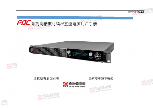
用户手册Rev1.3 系列高精度可编程直流电源用户手册版权所有翻印必究如有变更恕不通知目录1联系我们 (2)2保修和安全信息 (3)2.1有限售后保证 (3)2.2安全 (4)2.3安全规则 (4)2.4安全标识含义 (4)2.5安全信息 (5)2.6安全注意事项 (7)3产品概述 (14)3.1一般说明 (14)3.2产品特点 (18)3.3系统框图 (19)I3.4操作描述 (20)3.5附件 (20)4技术规格 (22)4.1产品型号 (22)4.2技术规格 (26)4.3外形尺寸 (37)4.4输出电压和电流曲线 (37)4.5环境 (41)4.6音频噪声与输出电流 (42)4.7音频噪声和环境温度 (43)4.8安规与认证 (44)5开箱和安装 (45)5.1检查与开箱 (45)II5.2搬运与存储 (45)5.3后面板布局 (47)5.4输入连接 (50)5.5桌面使用 (52)5.6机架安装 (53)5.7噪声水平 (54)5.8液体防护 (54)5.9清洁 (54)5.10负载连接 (55)5.10.1单负载连接(默认) (55)5.10.2多负载连接 (55)5.11远端补偿连接 (58)5.11.1单负载电压补偿 (58)III5.11.2多负载电压补偿 (59)5.12并机连接 (61)5.13串联连接 (64)5.13.1电压扩容 (65)5.13.2正负电源 (66)6面板操作与控制 (68)6.1面板布局 (68)6.2飞梭操作介绍 (72)6.2.1主界面操作 (72)6.2.2设置界面操作 (73)6.3启动方式 (75)6.3.1启动方式功能 (75)6.3.2启动方式设置 (75)IV6.3.3开机操作 (77)6.3.4关机操作 (77)6.4随动/预览 (78)6.4.1随动/预览功能 (78)6.4.2随动/预览设置 (78)6.5工作模式 (80)6.5.1恒压模式 (80)6.5.2恒流模式 (81)6.5.3恒压恒功率模式 (82)6.5.4恒流恒功率模式 (83)6.6上升下降时间设置 (84)6.7内阻 (85)6.7.1内阻功能 (85)V6.7.2前面板内阻设置 (85)6.8给定来源 (87)6.9触发功能 (89)6.9.1触发参数功能 (89)6.9.2前面板触发系统设置 (90)6.9.3前面板触发参数设置 (92)6.10保护和限制功能 (94)6.10.1故障复位 (96)6.10.2电压保护和限制 (96)6.10.3电流保护和限制 (99)6.10.4功率保护和限制 (101)6.10.5折返保护功能 (106)6.11编程功能 (107)VI6.11.1编程数据 (109)6.11.2标准编程接口 (109)6.11.3扩展编程接口 (112)6.11.4编程举例 (115)6.12键盘锁定功能 (119)6.13远程通信设置 (121)6.13.1本/远控切换功能 (121)6.13.2前面板远程通信设置 (121)6.14参数存取 (125)6.14.1参数存储和读取 (125)6.14.2保存当前参数 (126)6.14.3默认参数列表 (127)6.15计量功能 (130)VII6.16按键亮度 (133)6.17预置负载 (134)6.18并机功能 (135)6.18.1并机功能 (135)6.18.2并机数显示 (137)6.18.3从机号设置 (137)7模拟编程控制 (139)7.1简介 (139)7.2模拟编程使能 (142)7.3模拟编程信号 (143)7.4模拟电压编程输出电压和电流 (144)7.5模拟电阻编程输出电压和电流 (146)7.6输出电压和电流模拟指示 (149)VIII7.7辅助输出功能 (150)7.8电源输出使能 (152)7.9内部锁定功能 (154)7.10运行指示 (156)7.11连锁故障 (157)7.12截流指示 (159)8远端控制 (160)8.1概述 (160)8.2配置 (160)8.2.1控制方式设置 (161)8.2.2通信接口选择 (162)8.2.3地址设置 (162)8.2.4波特率设置 (163)IX8.2.5IP地址设置 (163)8.2.6端口号设置 (164)8.3RS232/RS485输入端口 (165)8.4RS485输出端口 (166)8.5RS232接线示意 (167)8.6RS485接线示意 (168)8.7USB通信端口 (169)8.8后面板LAN (170)8.8.1概述 (170)8.8.2规格 (170)8.8.3LAN远控方式配置 (172)8.8.4网络连接 (173)8.9多机控制 (176)X8.9.1概述 (176)8.9.2配置 (176)8.9.3设备握手功能 (178)8.9.4接收使能功能 (178)8.9.5全局控制功能 (178)8.10错误队列功能 (180)8.10.1概述 (180)8.10.2功能描述 (180)8.11SCPI指令概述 (182)8.12SCPI通信规约 (182)8.12.1常用符号 (182)8.12.2参数格式 (183)8.12.3SCPI指令介绍 (184)XI8.12.4执行次序 (188)8.13共同指令 (189)8.14仪器指令 (193)8.14.1测量指令 (194)8.14.2设置指令 (197)8.14.3系统指令 (218)8.14.4状态指令 (222)8.14.5输出指令 (229)8.14.6全局指令 (233)8.14.7设备指令 (236)8.14.8启动指令 (237)8.14.9触发指令 (238)8.14.10编程指令 (241)XII1联系我们地址:中国·陕西·西安新型工业园区信息大道12号邮编:710119电话:+86(029) 85691870 85691871 85691872传真:+86(029) 85692080网址:邮箱:******************22保修和安全信息2.1有限售后保证西安爱科赛博电气股份有限公司对所制造及销售的PDC产品自交货之日起一年内,保证在正常使用情况下产生的故障或损坏,负责免费维修。
KMB+K Precision程序可编程直流电源说明书
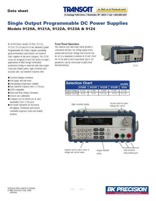
B+K Precision ®models 9120A,9121A,9122A,9123A and 9124are laboratory grade Programmable DC Power Supplies providing great performance and features not found in other supplies in this price category.The 9120series are designed to meet the needs of today’s applications in R&D design verification,production testing or university labs that require clean and reliable power,high resolution and accuracy and fast transient response time.IExcellent display resolution I Low ripple and low noiseI Outstanding temperature stabilityI Fast transient response time (<150µs)I SCPI compatibleI Front and Rear Output T erminals I Closed case calibrationI Compact size for bench use or rack mountable (2U x 1/2U size)I List mode operation for increased throughput.Download and execute command sequences from non-volatile memory91244mm sheathed safety banana jacksOutput ON/OFF switchEncoder knob for quick analog style controlNumeric keys for direct entry of voltage and current valuesHigh resolution displayFront Panel OperationThe numeric keys and rotary knob provide a convenient interface for setting output levels quickly and precisely.Voltage and Current can be set to a maximum resolution of 0.5mV (2mV for 9124)and 0.1mA respectively.Up to 50parameters can be stored and recalled from internal memory.Data sheetTechnical data subject to change ©B&K Precision Corp.2008v031609Single Output Programmable DC Power SuppliesModels 9120A, 9121A, 9122A, 9123A & 9124DVM and m ΩmeterUser accessible fuseT emperature controlled cooling fan Serial interface connector for RS232 or USB communication.(USB communication cable is optional).Model 9123A also supports control via GPIB interface.Remote Sense and digital port functionalityThe 9120 series uses 4mm sheathed banana jacks that accept sheathed or shrouded banana plugs and meet the latest international safety standards.Extra FeaturesThe 9120 series’ digital port offers a variety of configurations. The port can operate in Digital I/O,external Trigger and DFI/RI (Discrete FaultIndicator/Remote Inhibit) mode. The RI feature can be used for turning several power supplies On/Off simultaneously. External triggering can be used in combination with List mode.The included Application Software supports front panel emulation and allows users to generate simple test sequences without the need to write source code.Additionally, the power supply comes with a built-in 51/2 digit DVM and high resolution milliohm meter supporting 4 wire measurements.Remote InterfaceThe power supplies can be remotely controlled from any PC with USB or RS232 interface, allowing the user to program and monitor all parameters through easy to use SCPI commands.The power supplies come with a RS232 to TTL serial converter cable. A USB to serial converter cable is available as option. Additionally, model 9123A can be controlled via GPIB interface and includes a GPIB to TTL conversion adapter cable.2Single Output Programmable DC Power Supplies Models 9120A, 9121A, 9122A, 9123A & 9124。
创新可靠电源系列可编程电源EMEA-第2版说明书
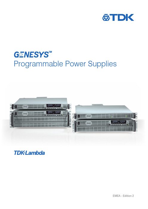
Programmable Power SuppliesEMEA - Edition 2Smallest and lightest product on the market + Highest power density on the market Versatile communication protocols+High functionality + Simplifies control Speeds up test times The family of programmable power supplies setsa new standard for flexible, reliable, AC-DC power systems in OEM, Industrial and Laboratory applications.The next generation has arrived. And it´s small and mighty.2Specifications• 1.7-5kW in 1U• 10kW in 2U / 15kW in 3U• W ide Range of popular worldwide AC inputs: G5kW - G15kW: 3Ø (208, 400 & 480Vac), Wide range 3Ø 480Vac (342~528Vac) G1.7kW: 1Ø (85~265Vac)• O utput Voltage up to 600V, Current up to 1500A • 5 year warrantyApplications• T est & Measurement systems, Component Device Testing, Manufacturing and process control • S emiconductor Processing & Burn-In,Aerospace & Satellite Testing, Medical Imaging, Green Technology•A TE, Automotive, Automation, Laser diodes, Battery simulation• H igher power systems can be configured with up to four 5kW units. Each unit is 1U with zero space between them (zero stack)•O EM Designers have a wide variety of inputs and outputs from which to select depending on application and locationFeaturesGeneral• 1U benchtop and 19 Inch standard rack package • C onstant voltage/constant current operation modes/constant power (CP) Limit • Internal Resistance SimulationControl interfaces• H igh resolution 16 bit ADCs & DACs • R• I • I ntegrated Anybus CompactCom interface platform •C ommunications compatible with Z+ and Genesys TM Programming• A rbitrary Waveform Generator with Auto-Triggering (store up to 100 steps into four internal memory cells) • S lew-Rate Control (V/I)• T wo user programmable output control pins (open drain) to activate external devices• E asy auto-configuration for parallel systems up to 20kW • S afe or Auto re-start and last settings memoryEnvironmental• F an speed profile controlled by ambient temperature and load •E fficiency up to 92% Mechanical• H igh contrast, wide viewing angle LCD display with brightness and dimming control • B lank front panel option • F ront Panel dust filter optionFind out more at: /genesysplus31. Input Power ON/OFF Switch2. Air Intake allows zero stacking for maximum system flexibility and power density3. Reliable Detent Encoders for settings and Menu navigation4. High Contrast/Brightness display with wide viewing angle, 16 segment LCD5. Function/Status LEDs: Active modes and function indicators6. Pushbuttons allow flexible user configuration1. Isolated Analogue Programming, Monitoring and other control connector (DB26 Female)2. USB Interface connector (Type B)3. RS-232/RS-485 IN/OUT Remote Digital Interface (RJ-45 type) for Multi-Drop connection5. Auto paralleling Bus connectors (mini I/O type) for connecting Master unit-to-Slave and slave unti-to-slave unit6. Remote/Local Output Voltage Sense Connections (spring cage)7. O utput Connections: Rugged busbars (shown) for models up to and including 100V Output;Plug connector: PHOENIX CONTACT IPC 5/4-STF-7.62 for models with Outputs >100V8. G 5kW Input: 208, 400 & 480Vac Three Phase, 50/60Hz (Model shown)AC Input Plug Connector: PHOENIX CONTACT Power Combicon PC 5/4-STCL1-7.62 Series with strain relief G1.7kW Input: 85~265Vac, Single Phase, 50/60HzAC Input Plug Connector: PHOENIX CONTACT Power Combicon PC 5/3-STCL1-7.62 Series with strain relief 9. Optional Interface Position for IEEE 488.2 SCPI or Anybus Interface10. Exhaust air assures reliable operation when units are zero stacked1 1. Functional Ground connection (M4x8mm stud)12345671011891234653Panel DescriptionFront Panel GENESYS+™ G (1.7-5kW) NEWRear Panel GENESYS+™ G (1.7-5kW) NEW4Front Panel GENESYS+™ GSP (10kW) NEWRear Panel GENESYS+™ GSP (10kW) NEW 51. Input Power ON/OFF Switch2. Air Intake allows zero stacking for maximum system flexibility and power density3. Reliable Detent Encoders for settings and Menu navigation4. High Contrast/Brightness display with wide viewing angle, 16 segment LCD5. Function/Status LEDs: Active modes and function indicators6. Pushbuttons allow flexible user configuration12346531. Isolated Analogue Programming, Monitoring and other control connector (DB26 Female)2. USB Interface connector (Type B)3. RS-232/RS-485 IN/OUT Remote Digital Interface (RJ-45 type) for Multi-Drop connection5. Auto paralleling Bus connectors (mini I/O type) for connecting Master unit-to-Slave and slave unit-to-slave unit6. Remote/Local Output Voltage Sense Connections (spring cage)7. O utput Connections: Rugged busbars (shown) for models up to and including 100V Output;Plug connector: PHOENIX CONTACT DFK-IPC 16/4-STF-10.16 for models with Outputs >100V 8. I nput: 208, 400 & 480Vac Three Phase, 50/60HzAC Input Plug Connector: PHOENIX CONTACT DFK-IPC 16/4-STF-10.16 with strain relief 9. Optional Interface Position for IEEE 488.2 SCPI or Anybus Interface 10. E xhaust air assures reliable operation when zero stacked11. Functional Ground connection (M4x8mm stud)1102345678911Front Panel GENESYS+™ GSP (15kW)NEWRear Panel GENESYS+™ GSP (15kW) NEW61. Input Power ON/OFF Switch2. Air Intake allows zero stacking for maximum system flexibility and power density3.Reliable Detent Encoders for settings and Menu navigation 4. High Contrast/Brightness display with wide viewing angle, 16 segment LCD 5. Function/Status LEDs: Active modes and function indicators 6.Pushbuttons allow flexible user configuration 1. Isolated Analogue Programming, Monitoring and other control connector (DB26 Female) 2. USB Interface connector (Type B)3. RS-232/RS-485 IN/OUT Remote Digital Interface (RJ-45 type) for Multi-Drop connection 5. Auto paralleling Bus connectors (mini I/O type) for connecting Master unit-to-Slave and slave unit-to-slave unit 6. Remote/Local Output Voltage Sense Connections (spring cage)7. O utput Connections: Rugged busbars for models up to and including 100V Output;Plug connector: PHOENIX CONTACT DFK-IPC 16/4-STF-10.16 for models with Outputs >100V (shown) 8. I nput: 208, 400 & 480Vac Three Phase, 50/60 HzAC Input Plug Connector: PHOENIX CONTACT DFK-PC 16/4-ST-10.16 with strain relief 9. Optional Interface Position for IEEE 488.2 SCPI or Anybus Interface10. Exhaust air assures reliable operation when zero stacked11. Functional Ground connection (M4x8mm stud)12346531102345678911AUTO-start SAFE-start Indicator FOLDbackVoltageCurrentIndicatorPower SupplyAddress &Power IndicatorRemote Communication Active,RS-232/-485, USB, LAN, OPT(GPIB, Anybus, etc…)LFP (Locked Front Panel)TRIGger Active Memory–Cell (Sequence)Front Panel Display MENU/CONTROL buttonsGENESYS+™ G&GSP Series Blank Front PanelA Blank Front Panel is available for applications where the front panel display and controls are not required and only remote interface (digital/analogue) is needed.The Blank Front Panel option has all the standard product functions and features except the display. The power supply can bec ontrolled via the rear panel Remote digital interface (LAN, USB, RS-232/RS-485) or via the remote Isolated Analogue interface.GENESYS+™ Parallel and Series ConfigurationsParallel operation – Master/Slave• A uto paralleling Scalable Master-Slave Operation• A ctive current sharing allows up to four identical units to be connected •T otal Real Current is programmed, measured and reported by the Master • U p to four supplies operate as oneScalable Power SystemsFactory assembly and test available for two and three unit systems 10kW/15kW. Parallel kit available for four unit systems 20kW. Order P/N: G/P - 4UGSP 10kW in 2U GSP 15kW in 3USeries operationTwo units may be connected in series to increase the output voltage or to provide bipolar output.(Max. 600V to Chassis Ground).Standard Unit - Zero stacked up to 4 units Standard & Blank - Zero stacked up to 4 units8POWER (LED)1Graphical User InterfaceAdvanced “Virtual Front Panel” allows programming and monitoring units with or without front panel display.GUI Waveform Profile generatorUser Interface• Control and monitor up-to 31 units with “Address” bar •F ront panel set-up menu control (PROGram, SYSTem, CONFIguration, PROTection and COMMunication)• Informative “Parameters” status bar • Individual unit and Global command control • Data logging including errors, events and recovery • R ealtime Graph and Waveform creator, store/load sequence•S olar array mode - calculate MPP (Max Peak Power) for solar array• R egisters View: Operation Status, Fault, Event Status, ENABLE and INTERLOCK signals• Remote communication state LOC, REM, LLO • Programmed signals 1&2 9Technical Specifications:Unit with Air Filter Assembly Installed• Derating (enviromental)• Operating Temperature• F or all models (except 10V): 0°C to +40°C For 10V model: 0°C to +30°C, derate 5A/°C for 30°C < TA < +40°C • Altitude• F or all modells (except 10V): derate 2°C/100m or 2% of load/100m (above 2000m)• F or 10V model: derate 1°C/100m or 2% of load/100m (above 2000m)Air Filter Assembly Components Standard Unit (P/N: G-AFK)• Air Filter Cover (two pieces)• S lide Button #1 (two locations:near AC ON/OFF switch and near left-hand side of front panel display)• S lide Button #2 (one location: right-hand side of front panel display)• Filter foam (two pieces)GENESYS+™ Front Panel Air Filter AssemblyFront panel dust cover is available for dusty air environment applications. Dust cover is removable snap-in filter (for easy maintenance)Part Number (for standard unit): G-AFKPart Number (for unit with blank front panel): GB-AFKFor GSP 10kW/15kW series order part number: GSP10kW-AFK / GSP15kW-AFKAir Filter KitFilter Foam Technical Specifications• Material: reticulated polyurethane foam • Thickness: 4.0mm • Porosity: 30ppi• Operating Temperature Range: 0°C to +60°C • Storage Temperature Range: -40°C to +85°C • Humidity: 95% RHBlank Front Panel Unit (P/N: GB-AFK)• Air Filter Cover (one piece)• Slide Button #1 (two locations)• Filter foam (one piece)10RS-485 LinkLAN, USB,RS-232/RS-485, IEEE, AnybusRS-485 LinkMulti-Drop Remote Programming via Communication InterfaceStandard Built-in LAN, USB, RS-232 & RS-485 allows “Multi-Drop” daisy-chain control of up to 31 Power supplies on the same communication bus. Can be Daisy chained via built-in RS-485 Interface.• First unit is LAN, USB, RS-232, RS-485, etc.• All other untis use RS-485 daisy chain with linking cable.GENESYS+™ Family Output Voltage and CurrentAC Input RangeProduct SummaryModel Output Voltage [Vdc]Output Current [A]OutputPower [W]AccessoriesAccessories will be sent separatly from the Power Supply packing, according to order.1. S erial Communication cable – RS-232/RS-485 cable is used to connect the power supply to the Host PC.Mode PC Connector Power Supply Connector Communication Cable P/N RS-232DB-9F RJ-45Shielded L=2m GEN/232-9RS-485DB-9FRJ-45Shielded L=2mGEN/485-92. S erial Link cable (included with the power supply) Daisy-chain up to 31 GENESYS+™ power supplies.Mode Power Supply Connector Communication Cable P/N RS-485RJ-45Shielded L=50cmGEN/RJ453. B us Paralleling cable Connectors CablesP/N 2013595-1 (TYCO)Shielded L=11cmG/P4. U ser Manual Printed User ManualG/MModels GENESYS+™ G (1.7kW) NEWProduct Code-10-170--Series NameOutput Voltage (0~10V)Output Current (0~170A)Interface OptionsAccessories OptionsAC Input (All Models) P/N: 1Ø, 85~265Vac- Accessories Options P/N:Printed User ManualM (User Manual & GUI on CD as Standard)Bus Paralleling CablePModel Output Voltage [Vdc]Output Current [A]Output Power [W]Model Output Voltage [Vdc]Output Current [A]Output Power [W]AccessoriesAccessories will be sent separatly from the Power Supply packing, according to order.1. S erial Communication cable – RS-232/RS-485 cable is used to connect the power supply to the Host PC.Mode PC Connector Power Supply Connector Communication Cable P/N RS-232DB-9F RJ-45Shielded L=2m GEN/232-9RS-485DB-9FRJ-45Shielded L=2mGEN/485-92. S erial Link cable (included with the power supply) Daisy-chain up to 31 GENESYS+™ power supplies.Mode Power Supply Connector Communication Cable P/N RS-485RJ-45Shielded L=50cmGEN/RJ453. B us Paralleling cable Connectors CablesP/N 2013595-1 (TYCO)Shielded L=11cmG/P4. U ser Manual Printed User Manual G/M5. P arallel Kit: 20kWBusBar Parallel Kit for 20 kW operation (5kW Models where Vout up to 100V)G/P-4U Models GENESYS+™ G (5kW)Product Code-10-500---Series NameOutput Voltage (0~10V)Output Current (0~500A)Interface OptionsAC Input OptionsAccessories OptionsAC Input OptionsP/N: Three Phase 170~265Vac 3P208 Three Phase 342~460Vac 3P400 Three Phase 342~528Vac3P480 Accessories Options P/N:Printed User ManualM (User Manual & GUI on CD as Standard)Bus Paralleling CablePModel Output Voltage [Vdc]Output Current [A]Output Power [kW]Model Output Voltage [Vdc]Output Current [A]Output Power [kW]Model Output Voltage [Vdc]Output Current [A]Output Power [kW]Model Output Voltage [Vdc]Output Current [A]Output Power [kW]Models GENESYS+™ GSP (10kW) NEWModels GENESYS+™ GSP (15kW)AC Input Options:P/N: Three Phase 170~265Vac 3P208 Three Phase 342~460Vac 3P400 Three Phase 342~528Vac3P480 Accessories Options: P/N:Printed User ManualM (User Manual & GUI on CD as Standard)Bus Paralleling CablePSpecifications Specifications GENESYS+™ G (1.7kW)*1: Minimum voltage is guaranteed to maximum 0.1% of rated output voltage.*2: Minimum current is guaranteed to maximum 0.2% of rated output current.*3: For cases where conformance to various safety standards (UL, IEC, etc…) is required, to be described as 100-240Vac (50/60Hz).*4: Signal and control ports interface cables length: Less than 3m, DC output power port cables length: Less than 30m. *5: Not including EMI filter inrush current, less than 0.2mS.*6: 85~132Vac or 170~265Vac. Constant load.*7: From No-Load to Full-Load, constant input voltage. Measured at the sensing point in Remote Sense.*8: For 10V~150V models: Measured with JEITA RC-9131C (1:1) probe. For 300~600V model: Measured with 100:1 probe.*9: For load voltage change, equal to the unit voltage rating, constant input voltage.*10: The maximum voltage on the power supply terminals must not exceed the rated voltage.*11: From 10% to 90% or 90% to 10% of Rated Output Voltage, with rated, resistive load.*12: From 90% to 10% of Rated Output Voltage.*13: F or 10V model, the ripple is measured at 2V and rated output current.For other models, the ripple is measured at 10% of rated output voltage. B.W 5Hz~1MHz.*14: T he Constant Current programming, readback and monitoring accuracy do not includethe warm-up and Load regulation thermal drift.*15: Measured at the sensing point.*16: Maximum ambient temperature for IEEE option is 40°C.*1: Minimum voltage is guaranteed to maximum 0.1% of rated output voltage.*2: Minimum current is guaranteed to maximum 0.2% of rated output current.*3: Derate 5A/1°C above 40°C.*4: F or cases where conformance to various safety standards (UL, IEC, etc...) is required, to be described as 190-240Vac (50/60Hz) for 3-Phase 200V models, 380~415Vac (50/60Hz) for 3-Phase 400V models and 380~480Vac (50/60Hz) for 3-Phase models.*5: 3-Phase 200V models: At 200Vac input voltage, 3-Phase 400/480V: At 380Vac input voltage. With rated output power.*6: Not including EMI filter inrush current, less than 0.2mS.*7: 3-Phase 200V models: 170~265Vac, 3-Phase 400V models: 342~460Vac, 3-Phase 480V models: 342~528Vac. Constant load. *8: From No-Load to Full-Load, constant input voltage. Measured at the sensing point in Remote Sense.*9: For 10V~150V models: Measured with JEITA RC-9131C (1:1) probe. For 300~600V model: Measured with 100:1 probe.*10: The maximum voltage on the power supply terminals must not exceed the rated voltage.*11: From 10% to 90% or 90% to 10% of Rated Output Voltage, with rated, resistive load.*12: From 90% to 10% of Rated Output Voltage.*13: For load voltage change, equal to the unit voltage rating, constant input voltage.*14: F or 10V model the ripple is measured at 2V and rated output current.For other models, the ripple is measured at 10% of rated output voltage. B.W. 5Hz~1MHz.*15: T he Constant Current programming, readback and monitoring accuracy do not include the warm-up and Load regulation thermal drift.*16: Measured at the sensing point.*17: For 10V model Ta derating 2°C/100m.*18: S ignal and control ports interface cables length: Less than 3m,DC output power port cables length: Less than 30m.*19: Max. ambient temperature for using IEEE is 40°C.*20: For 10V model only: Max. output current for using IEEE is 400A up to 40°C and 450A up to 30°C.Specifications GENESYS+™ GSP (10/15kW)21*1: Minimum voltage is guaranteed to maximum 0.1% of rated output voltage.*2: Minimum current is guaranteed to maximum 0.2% of rated output current.*3: Derate 10A/1°C above 40°C. *4: F or cases where conformance to various safety standards (UL, IEC, etc...) is required, to be described as 190-240Vac (50/60Hz) for 3-Phase 200V models, 380~415Vac (50/60Hz) for 3-Phase 400V models and 380~480Vac (50/60Hz) for 3-Phase 480V models.*5: 3-Phase 200V models: At 200Vac input voltage, 3-Phase 400/480V: At 380Vac input voltage. With rated output power.*6: Not including EMI filter inrush current, less than 0.2mS.*7: 3-Phase 200V models: 170~265Vac, 3-Phase 400V models: 342~460Vac, 3-Phase 480V models: 342~528Vac. Constant load.*8: From No-Load to Full-Load, constant input voltage. Measured at the sensing point in Remote Sense.*9: For 10V~150V models: Measured with JEITA RC-9131C (1:1) probe. For 300~600V model: Measured with 100:1 probe.*10: The maximum voltage on the power supply terminals must not exceed the rated voltage.*11: From 10% to 90% or 90% to 10% of Rated Output Voltage, with rated, resistive load.*12: From 90% to 10% of Rated Output Voltage.*13: For load voltage change, equal to the unit voltage rating, constant input voltage.*14: F or 10V model the ripple is measured at 2V and rated output current.For other models, the ripple is measured at 10% of rated output voltage. B.W. 5Hz~1MHz. *15: T he Constant Current programming, readback and monitoring accuracydo not include the warm-up and Load regulation thermal drift.*16: Measured at the sensing point.*17: For 10V model Ta derating 2°C/100m.*18: S ignal and control ports interface cables length:Less than 3m, DC output power port cables length: Less than 30m. *19: Max. ambient temperature for using IEEE is 40°C.*20: F or 10V model only: Max. output current for using IEEE is 800A up to 40°C and900A up to 30°C (GSP10kW); 1200A up to 40°C and 1350A up to 30°C (GSP15kW)Outline Drawing GENESYS+™ G (1.7/5kW)Outline Drawings22Outline Drawing GENESYS+™ G (1.7/5kW)(Models 150V/300V/600V)23Outline Drawing GENESYS+™ GB (1.7/5kW)24Outline Drawing GENESYS+™ GSP (10kW)25Outline Drawing GENESYS+™ GSP (15kW)26Outline Drawing GENESYS+™ Air Filter Kit2710_2018 l a m _108459W h i l s t T D K -L a m b d a t r i e s t o e n s u r e t h a t t h e i n f o r m a t i o n c o n t a i n e d i n t h i s C a t a l o g u e i s a c c u r a t e i t d o e s n o t a c c e p t l i a b i l i t y f o r a n y i n a c c u r a c i e s . I n e x c e p t i o n a l c i r c u m s t a n c e s T D K -L a m b d a r e s e r v e s t h e r i g h t , w i t h o u t n o t i c e o r l i a b i l i t y , t o w i t h d r a w p r o d u c t s o r a l t e r s p e c i f i c a t i o n s a t a n y t i m e .Get in contact to find the best solution to your application.DISTRAME S.A. - Parc du Grand Troyes - Quartier Europe Centrale - 40, rue de Vienne - 10300 SAINTE-SAVINE Tél. : +33 (0)3 25 71 2583-Fax:+33(0)325712898-E-mail:******************************:www.distrame.fr。
PPCL编程手册范本
西门子楼宇科技现场控制器控制程序 (PPCL) 基本概论及指令说明(Powers Process Control Language, PPCL)第2.0版2001/5/22修订1.基本概论1.1现场控制器控制程序(Powers Process Control Language, PPCL)现场控制器 DDC 会经由一组顺序之指令,执行系统的控制及能源管理。
PPCL 是由各种型态的指令所构成,每一行指令皆根据一特殊的格式,来执行一特殊的任务。
PPCL 是根据已建立在数据库内的系统监控点,以及事先定义的特殊逻辑点与变量来运作的。
这些特殊逻辑点具有一特定保留的点名称,并且是常驻于控制器的通讯控制卡(Line Card)内。
1.2PPCL 程序程序是一组告诉计算机如何处理指令的信息集。
而 PPCL 程序包含的每一行指令,控制器会以一行接一行(Step-by-step)的方式来处理这些程序。
1.3 PPCL 程序的操作原理PPCL 运作时,会对一组程序中每一行程序不断地执行,但每一次只执行一行程序,然后再执行下一行程序。
在最后一行程序执行完毕后(最后一行程序为行号数最大的程序),控制器会回到程序的第一行,继续执行程序。
当每一行程序被执行时,若该行程序具有监控点,则控制器会审视系统监控点数据库,若有需要,监控点亦会被控制,而各监控点最后的数值或状况会被应用。
换言之,每一行程序所使用的数值或状况亦为各监控点最后的数值或状况, 而若参考之监控点为输出点,则该点最后被控制的状况或数值,会被程序参考,这个意思表示,在 PPCL 程序执行的过程中,一特定监控点的数值或状况可能会改变很多次,或者没有改变。
任何未被解析的 PPCL 程序,皆不会被执行。
而所谓的未被解析的 PPCL 程序是指,该行程序或内所包含的系统监控点,没有被定义,或没有出现在网络上。
PPCL 程序内含有失效(Failed)或操作者除能(Operator Disabled)监控点时之运作:当一 PPCL 程序内所含之监控点,其操作状态为失效或已被操作者除能时,该行 PPCL 程序仍会被执行,而所用监控点的数值或状态,为该点尚未失效或被操作者除能前的最后一已知数值或状态。
