丹佛斯FC-300变频器说明书
丹佛斯变频器FC300的使用

三号线变频器FC300的使用2012年6月24日三号线变频器FC300的使用 (1)一、安装 (3)1、变频器的安装 (3)2、电气安装图 (4)3、最终设置与测试 (4)4、维修注意事项 (5)二、编程 (6)1、本地控制面板上编程 (6)2、FC 300软件对话 (7)三、常见问题的解决 (8)1、警告/报警信息 (8)2、常见报警故障 (8)3、Live zero error(断线故障) (9)一、安装1、变频器的安装1. 使用附件包中的螺钉和垫圈将去耦板固定到FC 300的底部。
2. 将电动机电缆连接到端子96 (U)、97 (V)、98 (W) 上。
3. 使用附件包中的螺钉连接去耦板上的接地线(端子99)。
4. 将端子96 (U)、97 (V)、98 (W) 和电动机电缆插入标有MOTOR(电动机)的端子。
5. 使用附件包中的螺钉和垫圈将屏蔽电缆固定到去耦板上。
2、电气安装图注:控制电缆必须带有屏蔽/铠装。
3、最终设置与测试要对设置进行测试并且确保FC 300 运行,请执行以下步骤。
步骤1. 找到电动机铭牌。
步骤2. 在该列表中输入电动机铭牌数据。
1. 电动机功率[kW] 参数1-202. 电动机电压参数1-223. 电动机频率参数1-234. 电动机电流参数1-245. 电动机额定转速参数1-25步骤3. 启动自动电动机调整,AMA建议运行AMA 以确保获得最佳性能。
AMA 会测量来自图表(相当于电动机模型)的数据。
1. 启动FC 300,并激活AMA 参数1-29。
2. 选择是运行完整的还是精简的AMA。
如果安装了LC 滤波器,则只能运行精简的AMA。
3. 按[OK](确认)键。
显示器显示"Press hand to start"(按手动键开始)。
4. 按[Hand on](手动)键。
位于显示器底部的进度条表明是否正在运行AMA。
步骤4. 设置速度极限和加减速时间根据需要设置速度和加减速时间极限。
丹佛斯FC300变频一般设置
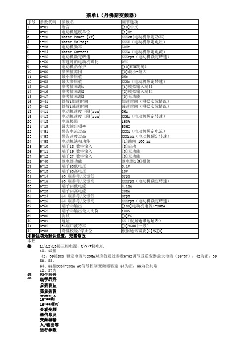
接线:12、18接启动信号常开点,18为1(高电平)时变频器启动
50、53、55接电位器,50为10V、 53为调节,55为公共端
12、37为安全停止功能,不能拆除
提示:绝不能将电源接至U\V\W端子,否则将损坏变频器
端子54开关拨至I(电流)位置
参数设置前必须熟悉控制原理图,部分参数应根据设计需要作相应调整
如参数设置错乱不易查找,可通过14-22项执行初始化操作恢复出厂设置,再行设置
15-**和16-**项可查看变频器信息及变频器输入/输出等运行参数L1\L2\L3接三相电源,U\V\W接电机
42、39接DCS 额定电流与20MA对应值通过参数6-52调节或逆变器最大电流(16-37),42为正,3954、55接DCS4-20mA AO信号控制变频器转速 54为正,55为公共端
菜单1(丹佛斯变频器)。
VLT Automation Drive FC 300(大功率型)操作手册说明书

端子位置 - 机架规格 F2 和 F4端子位置 - 整流器(F1、F2、F3 和 F4)(大功率型)操作手册3 如何安装3端子位置 – 选件机柜(F3 和 F4)3端子位置 – 带断路器/模壳开关的选件机柜(F3 和 F4)3.2.6冷却和气流冷却可以用不同方式实现冷却:在设备底部和顶部使用冷却道;使设备后部内外通风;或使用组合方式冷却。
风道冷却对于安装在 Rittal TS8 机箱中并利用自身风扇对暗道进行强制冷却的 IP00/机架机架式变频器,我们提供了一种优化安装的专用选件。
从机箱顶部排出的空气可以但却不会通过管道输送出设备,这样暗道损失的热量便不会在控制室内散逸,从而降低了设备的空气调节要求。
有关详细信息,请参阅 Rittal 机箱风管冷却套件的安装。
背部冷却暗道中的空气还可以从 Rittal TS8 机箱背部吸入和排出。
这提供了这样一种解决方案,其中暗道可以将设备中的空气排出并回收散逸到设备外部的热损失,从而降低了空气调节要求。
注意为了排出变频器暗道未涵盖的热量以及安装在机箱内的其它组件所产生的任何附加热量,在机箱上需要配备一个门装风扇。
为了选择适当的风扇,首先必须计算所要求的总气流量。
一些机箱厂商提供了相关的计算软件(如 Rittal Therm 软件)。
如果 VLT 是机箱内的唯一产热组件,则在 45 摄氏度的环境温度下所要求的最低气流量为:D3 和 D4 变频器为 391 m 3/h (230 cfm)。
在 45 摄氏度的环境温度下,E2 变频器所要求的最低流量为 782 m 3/h (460 cfm)。
气流必须保证散热片上有充足的气流。
以下是相关的流量。
表 3.3: 散热片气流注意以下原因将导致风扇转动:1.AMA 2.直流夹持3.预励磁4.直流制动5.超出额定电流的 60%6.超出特定的散热片温度(取决于功率大小)。
风扇一旦启动,至少将转动 10 分钟。
(大功率型)操作手册3 如何安装3外部风道如果在 Rittal 机柜外部添加了额外风道,则必须计算风道中的压降。
VLT AutomationDrive FC 300 变频器操作说明书

VLT®AutomationDrive FC 300 操作說明書目錄目錄1 如何閱讀操作說明書3認證4符號4縮寫52 安全說明及一般警告7高電壓7避免意外啟動8FC 300的安全停機8安全停機安裝,僅限 - FC 302 (且 FC 301 的機架大小為 A1)10IT 主電源103 如何安裝11機械安裝14電氣安裝16主電源連接與接地17馬達連接20保險絲23電氣安裝、控制端子27連接範例28電氣安裝,控制電纜線30開關 S201、S202 和 S80132其他連接35機械煞車控制35馬達熱保護35如何將電腦連接到變頻器36FC 300 PC 軟體364 如何進行程式設定37圖形化與與數值化 LCP37如何在圖形化 LCP 上進行程式設定37如何在數值化 LCP 操作控制器上進行程式設定38快速設定表單40基本設定參數43參數清單615 一般規格896 疑難排解95警告/警報訊息95索引1021 如何閱讀操作說明書VLT®AutomationDrive FC 300 操作說明書1VLT®AutomationDrive FC 300 操作說明書 1 如何閱讀操作說明書1如何閱讀操作說明書1VLT AutomationDrive操作說明書軟體版本:5.0x這些操作說明書適用於所有使用 5.0x 軟體版本的 VLT AutomationDrive 變頻器。
軟體版本號碼可以從參數 15-43 軟體版本上取得。
1.1.1如何閱讀操作說明書VLT AutomationDrive 可提供高效能的電氣馬達轉軸效能。
要正確使用,請仔細閱讀本手冊。
錯誤操作變頻器可能導致變頻器或相關設備操作異常、減低壽命或造成其他故障。
本操作說明書將協助您開始使用、安裝、進行程式設定和解決 VLT AutomationDrive.的問題。
VLT AutomationDrive 包含兩種轉軸效能等級。
丹佛斯变频器说明书
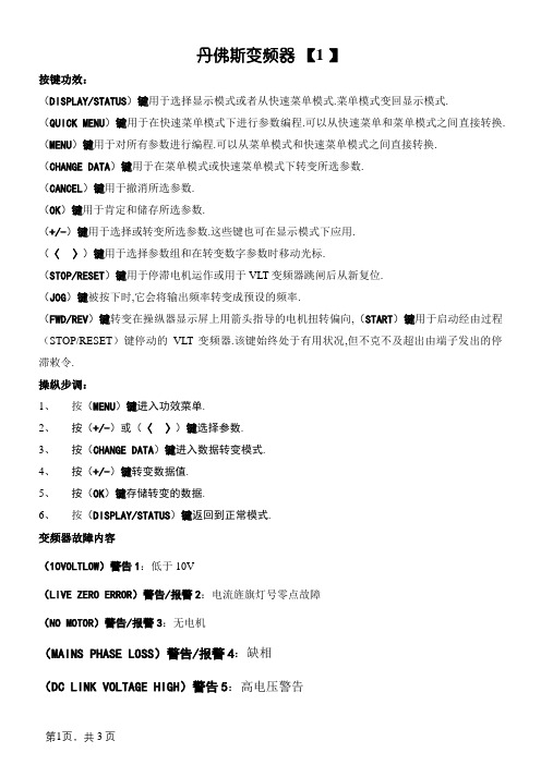
丹佛斯变频器【1 】按键功效:(DISPLAY/STATUS)键用于选择显示模式或者从快速菜单模式.菜单模式变回显示模式.(QUICK MENU)键用于在快速菜单模式下进行参数编程.可以从快速菜单和菜单模式之间直接转换. (MENU)键用于对所有参数进行编程.可以从菜单模式和快速菜单模式之间直接转换.(CHANGE DATA)键用于在菜单模式或快速菜单模式下转变所选参数.(CANCEL)键用于撤消所选参数.(OK)键用于肯定和储存所选参数.(+/-)键用于选择或转变所选参数.这些键也可在显示模式下应用.(〈〉)键用于选择参数组和在转变数字参数时移动光标.(STOP/RESET)键用于停滞电机运作或用于VLT变频器跳闸后从新复位.(JOG)键被按下时,它会将输出频率转变成预设的频率.(FWD/REV)键转变在操纵器显示屏上用箭头指导的电机扭转偏向,(START)键用于启动经由过程(STOP/RESET)键停动的VLT变频器.该键始终处于有用状况,但不克不及超出由端子发出的停滞敕令.操纵步调:1、按(MENU)键进入功效菜单.2、按(+/-)或(〈〉)键选择参数.3、按(CHANGE DATA)键进入数据转变模式.4、按(+/-)键转变数据值.5、按(OK)键存储转变的数据.6、按(DISPLAY/STATUS)键返回到正常模式.变频器故障内容(10VOLTLOW)警告1:低于10V(LIVE ZERO ERROR)警告/报警2:电流旌旗灯号零点故障(NO MOTOR)警告/报警3:无电机(MAINS PHASE LOSS)警告/报警4:缺相(DC LINK VOLTAGE HIGH)警告5:高电压警告(DC LINK VOLTAGELOW)警告6:低电压警告(DC LINK OVERVOLT)警告7:过电压(DC LINK UNDERVOLT)警告/报警8:欠电压(INVERTER TIME)警告/报警9:逆变器过载(MOTOR TIME)警告/报警10:电机温渡过高(MOTOR THERMISTOR)警告/报警11:电机过热(热敏电阻)(TORQUE LIMIT)警告/报警12:过转矩极限(OVERCURRENT)警告/报警13:过电流(EARTH FAULT)报警14:接地电流(SWITCH MODE FAULT)报警15:载波模式故障(CURR.SHORT CIRCUIT)报警16:短路(STD BUSTIMEOUT)警告/报警17:尺度总线无旌旗灯号(HPFB BUS TIMEOUT)警告/报警18:HPFB总线无旌旗灯号(EE ERROR POWER CARD)警告19:电源卡EEPROM故障(EE ERROR CTRL CARD)警告20:掌握卡EEPROM故障(AUTO MOTOR ADAPT OK)报警21:主动适配正常(BRAKE TEST FAILED)警告和报警22:制动核查中的故障(BRAKE RESISTOR FAULT)警告23:制动电阻故障(BRAKE PWR WARN 100%)警告24:制动电阻率100%(BRAKE IGBT FAULT)警告25:制动晶体管故障(HEAT SINK OVER TEMP)警告26:散热器温渡过高(MISSING MOT.PHASEU)报警27:电机U相缺掉(MISSING MOT.PHASE V)报警28:电机V相缺掉(MISSING MOT.PHASE W)报警29:电机W相缺掉(QUICK DISCHARGE NOT OK)报警30:快速放电不正常。
丹佛斯变频器FC使用说明定稿版
丹佛斯变频器F C使用说明HUA system office room 【HUA16H-TTMS2A-HUAS8Q8-HUAH1688】使用说明一、FC360的功能二、FC360本机面板使用HandON从出厂设定开始(未接控制线),首先,按【Off Reset】键使变频器处于停止状态,设定参数5-12改为【0】,退出到Status状态,这时,还是【Off Reset】键上的灯亮,按【OK】键,面板中心显示4位数值,设定手动频率,上下键增减,右键可窜位,设定好后,按【Hand on】键计开始运行,运行过程中直接按键改变数值则立即更改输出。
按【Off Reset】键停止。
设定的频率值将保持,再次按【Hand on】键,将从运行最后的设定值。
三、FC360参数设定方法:通用的参数设定方法:首先,按【Off Reset】键使变频器处于停止状态,按【MENU】键显示OM1状态此时在按一次【MENU】键则进入菜单1模式,按上键或下键可以修改参数组号,按【OK】进入此参数组,按上下键找到你需要改的参数号,按【OK】键该设定参数值闪烁,按上下键修改参数值(功能代码),若按【ok】键保存此次修改的参数。
若按【back】键则取消修改。
四、参数初始化修改参数14-22设定为2(初始化),然后从新上电,此时报警为A80,按【Off Reset】键复位后红色报警等已灭,但显示窗口仍有A80报警显示,变频器需再次从新上电。
五、参数复制到LCP面板。
修改参数0-50参数,当0-50,设为【1】所有参数到LCP,从变频器拷贝参数到面板,等待完成。
设为[2]则把面板中参数拷贝到变频器,从LCP传所有参数。
完成后参数自动改为【0】。
六、使用同步电机的设定步骤按下表设定:1、首先,设定1-00,1-01,1-10,及1-24,1-25,1-26(按电机铭牌)2、电机自学习AMA,设定1-29,为【1】,按OK键,按【Hand on】键,等待,经过一段时间,会显示“按【OK】键完成AMA”,按下【OK】键完成。
Danfoss VLT FC 300变频器设计指南说明书
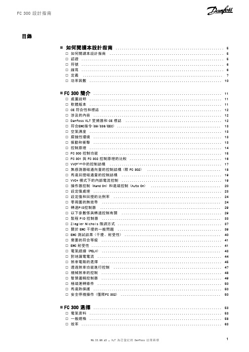
目錄!如何閱讀本設計指南 (5)"如何閱讀本設計指南 (5)"認證 (5)"符號 (6)"縮寫 (6)"定義 (7)"功率因數 (10)!FC300簡介 (11)"處置說明 (11)"軟體版本 (11)"CE符合性和標誌 (12)"涉及的內容 (12)"Danfoss VLT變頻器和CE標誌 (12)"符合EMC指令(89/336/EEC) (13)"空氣濕度 (13)"腐蝕性環境 (13)"振動和衝擊 (13)"控制原理 (14)"FC300控制功能 (15)"FC301與FC302控制原理的比較 (16)"VVC plus中的控制結構 (17)"無感測器磁通向量的控制結構(限FC302) (18)"馬達回授磁通量的控制結構 (19)"VVC+模式下的內部電流控制 (19)"操作器控制(Hand On)和遠端控制(Auto On) (20)"設定值處理 (23)"設定值和回授的比例率 (24)"零周圍的無效帶 (24)"轉速PID控制器 (29)"以下參數係與轉速控制有關 (29)"製程PID控制器 (33)"Ziegler Nichols微調方式 (37)"關於EMC干擾的一般問題 (39)"EMC測試結果(干擾、耐受性) (40)"需要的符合等級 (41)"EMC耐受性 (41)"電氣絕緣(PELV) (43)"對地漏電電流 (44)"煞車電阻的選擇 (45)"透過煞車功能進行控制 (47)"機械煞車的控制 (48)"智慧邏輯控制器 (49)"極端運轉條件 (50)"馬達熱保護 (50)"安全停機操作(僅限FC302) (50)!FC300選擇 (53)"電氣資料 (53)"一般規格 (58)"效率 (63)"噪音 (64)"馬達尖峰電壓 (64)"根據環境溫度降低額定值-數據在≤7.5kW時有效 (65)"根據氣壓降低額定值 (65)"低速運行時降低額定值 (65)"為安裝長的馬達纜線或大橫截面積的馬達纜線降低額定值 (65)"與溫度相關的載波頻率 (66)"機械尺寸 (67)"選項和配件 (68)"在插槽B中的安裝選項模組 (68)"一般用途輸入輸出模組MCB101 (68)"編碼器選配裝置MCB102 (70)"解析器選項MCB103 (71)"繼電器選配裝置MCB105 (73)"24V備用電源選項MCB107(選項D) (76)"煞車電阻器 (77)"LCP遠端安裝組件 (77)"IP21/IP4X/TYPE1外殼組件 (77)"IP21/Type1外殼組件 (77)"LC濾波器 (78)!如何訂購 (79)"變頻器訂貨代碼查詢軟體 (79)"訂購單類型代碼 (79)"訂購編號 (81)!如何安裝 (87)"機械安裝 (87)"配件包≤7.5kW (87)"機械安裝的安全要求 (89)"現場安裝 (89)"電氣安裝 (90)"移除額外電纜的擋板 (90)"主電源連接與接地 (90)"馬達連接 (92)"馬達電纜線 (94)"馬達電纜線的電氣安裝 (94)"保險絲 (95)"控制端子的進手 (97)"控制端子(FC301) (97)"電氣安裝、控制端子 (98)"基本配線範例 (98)"電氣安裝,控制電纜線 (99)"開關S201、S202和S801 (100)"最終的設定及測試 (101)"安全停機安裝(僅限FC302) (103)"安全停機試運轉測試 (104)"其他連接 (105)"負載共償 (105)"負載共償電纜線的安裝 (105)"煞車連接選項 (105)"繼電器連接 (106)"繼電器輸出 (107)"馬達並聯 (108)"馬達轉動方向 (108)"馬達熱保護 (108)"煞車電纜線的安裝 (108)"RS485總線的連接 (109)"如何將一部個人電腦連接至FC300 (109)"FC300Software Dialogue (110)"高電壓測試 (111)"安全接地的連接 (111)"電氣安裝-EMC預防措施 (111)"使用符合EMC規範的電纜線 (113)"有遮罩/有保護層的控制電纜線的接地 (114)"主電源干擾/諧波 (115)"殘餘電流器 (115)!應用範例 (117)"啟動/停機 (117)"脈衝啟動/停機 (117)"電位器設定值 (118)"編碼器連接 (118)"編碼器轉向 (118)"閉迴路變頻器系統 (119)"轉矩極限和停機的程式設定 (120)"馬達自動調諧(AMA) (120)"Smart Logic Control程式設定 (121)!如何進行程式設定 (123)"圖形化和數值化FC300LCP操作控制器 (123)"如何在圖形化LCP操作控制器上編寫程式 (123)"參數設定的快速傳輸 (126)"顯示模式 (127)"顯示模式-讀數選擇 (127)"參數設定 (128)"Quick Menu(快速表單)鍵功能 (128)"主設定表單模式 (129)"參數選擇 (130)"更改數據 (130)"更改文字值 (130)"更改一組數字型數據值 (131)"數字型數據值的無段可變式更改 (131)"以步進方式更改資料值 (132)"讀取和程式設定索引參數 (132)"如何在數值化LCP操作控制器上進行程式設定 (133)"操作器控制按鍵 (134)"初始化成為出廠設定 (135)"參數選擇-FC300 (136)"參數:操作和顯示 (137)"參數:負載和馬達 (144)"參數:煞車 (154)"參數:設定值/加減速 (157)"參數:限制/警告 (165)"參數:數位輸入/輸出 (169)"參數:類比輸入/輸出 (179)"參數:控制器 (184)"參數:通訊和選項 (187)"參數:Profibus (191)"參數:CAN Fieldbus (196)"智慧邏輯控制器 (200)"特殊功能 (209)"變頻器資訊 (212)"數據讀出 (217)"馬達回授選項 (222)"參數清單 (224)"協議 (241)"電報通信 (241)"電報結構 (241)"數據字元(位元組) (243)"製程字組 (248)"與FC描述檔對應的控制字組(CTW) (249)"根據FC描述檔對應的狀態字組(STW) (252)"根據PROFIdrive描述檔的控制字組(CTW) (254)"根據PROFIdrive描述檔對應的狀態字組(STW) (257)"串列通訊設定值 (259)"目前的輸出頻率 (260)"範例1:控制變頻器和讀取參數 (260)"範例2:僅用於控制變頻器 (261)"讀取參數的說明元素 (261)"其他文字 (266)!疑難排解 (267)"警告/警報訊息 (267)!Index (273)"如何閱讀本設計指南本設計指南將介紹有關FC300的所有內容。
FC300操作说明书

4 分钟 15 分钟 20 分钟 40 分钟 20 分钟 30 分钟
FC 300 操作说明 软件版本: 4.8x
这些操作说明适用于软件版本为 4.8x 的所有 FC 300 变频器。 通过参数 15-43 可以查看软件版本号。
2.1.1. 高压
当变频器与主电源连接时,它将带有危险电压。如果电动机或变频器的安装或操作不当,则可能导致设备损坏甚至严重的人员伤亡。因 此,必须遵守本手册中的规定以及相关的国家和地方条例和安全规定。
1. 如何阅读这些操作说明
AC
1
AWG
A
AMA
ILIM
°C
DC
D-TYPE
EMC
ETR
FC
g
Hz
kHz
LCP
m
mH
mA
ms
min
MCT
nF
Nm
IM,N
fM,N
PM,N
UM,N
par.
PELV
PCB
IINV
RPM
s
TLIM
V
MG.33.AA.41 - VLT® 是 Danfoss 的注册商标
5
2. 安全说明和一般警告
2
VLT®AutomationDrive FC 300 操作 说明
6
MG.33.AA.41 - VLT® 是 Danfoss 的注册商标
VLT®AutomationDrive FC 300 操作 说明
2. 安全说明和一般警告
2. 安全说明和一般警告
2
含电子元件的设备不能同生活垃圾一起处理。 您必须按照地方和现行法规将其与电气和电子废弃物一同回收处理。
第 6 章,疑难解答,帮助您解决在使用 FC 300 的过程中可能出现的问题。
丹佛斯起重和提升应用手册

7
飞轮矩的折算同起升机构。再根据式算出需要变频器提供的最大转矩大小。行走机构与提升 机构不同之处在于行走机构运行的时间长,惯量大,这就决定了行走机构的动态转矩在总转矩中 占有的比例要远大于起升机构,如果以总的转矩大小来选择变频器,可能会造成变频器容量的浪 费,而且运行机构安全性要求也没有起升机构高,完全可以将求得的变频器最大电流再除以变频 器的过载倍数来选择变频器大小,同以电机为标准的选型类似,当加速时间在 5min 之内大于 1min 时,就按照:
1
FC300 系列变频器起重和提升应用手册
丹佛斯(上海)自动控制有限公司 李 亮
一、起重和提升应用简介
起重和提升是国民经济中广泛应用的机械类型,涉及到工业,特别是重工业的方方面面,在 冶金、港口、采矿、造船、汽车等领域有着大量的应用需求。
起重和提升行业的控制在早期主要是以简单的电气和机械控制为主,随着电力电子技术和计 算机技术的发展,目前已经逐渐过渡到以“PLC+变频器”控制方式。其运行有如下特点:
佛斯 FC300 系列变频器就是这样一款高性能矢量型变频器。其控制方式有 4 种方式可选:U / f
控制,VVC+电压矢量,磁通矢量开环,磁通矢量闭环。平移机构由于其惯量较大,负载变化
相对较小,基本上属于阻力性负载,故大多采用U / f 开环控制方式。对于大车行走,往往还能
采用一台变频器同时驱动几台电动机的工作。起升机构由于惯量较小,负载变化从空载到满载变 化大,属于位能性负载。为了获得快速的动态响应,实现转矩的快速调节,获得理想的动态性能, 通常采用矢量控制方式。对于丹佛斯变频器,一般的起升应用采用磁通矢量开环的方式即可满足 要求,对于调速比较大或需要定位的吊装设备,使用丹佛斯变频器可以采用磁通矢量闭环的方式 以获得低速甚至是零速时稳定的转矩输出,获得良好的机械特性。
FC300系列操作手册

放电时间!
未打开变频器电源时,变频器直流回路的电容器可能仍有 电。为了避免出现电气事故,应断开交流主电源、所有永磁 电动机、所有远程直流回路电源,包括备份电池、UPS,以 及与其它变频器的直流回路连接。请等电容器完全放电后, 再执行维护或修理作业。等待时间详见放电时间表。如果 在切断电源后不等待规定的时间就执行维护或修理作业,将 可能导致死亡或严重伤害。
输出功率
• 为实现有效的操作和控制,输
入电源、内部处理、输出和电 动机电流都会受到监测
• 系统还会监测并执行用户界面
命令和外部命令
• 可以实现状态输出和控制
表 1.3 图 1.3 图例
6
MG33AM41 - VLT® 是 Danfoss 的注册商标
简介
VLT® AutomationDrive 操作 手册
表 1.2 图 1.2 的图例
11 继电器 2(04、05、06) 12 吊环 13 安装槽 14 接地线夹 (PE) 15 电缆应力消除/PE 接地 16 制动端子(-81、+82) 17 负载共享端子(直流总线)(-88、+89) 18 电动机输出端子 96 (U)、97 (V)、98 (W) 19 主电源输入端子 91 (L1)、92 (L2)、93 (L3)
2 安装
2.1 安装场址检查清单 2.2 变频器和电动机安装前检查清单 2.3 机械安装
2.3.1 冷却 2.3.2 起吊 2.3.3 安装 2.3.4 紧固力矩 2.4 电气安装 2.4.1 要求 2.4.2 接地要求 2.4.2.1 漏电电流 (>3.5 mA) 2.4.2.2 使用屏蔽电缆接地 2.4.3 电动机连接 2.4.4 交流主电源接线 2.4.5 控制线路 2.4.5.1 访问 2.4.5.2 控制端子类型 2.4.5.3 控制端子的接线 2.4.5.4 使用屏蔽型控制电缆 2.4.5.5 控制端子功能 2.4.5.6 跳线端子 12 和 27 2.4.5.7 端子 53 和 54 开关 2.4.5.8 机械制动控制 2.4.6 串行通讯 2.5 安全停止 2.5.1 端子 37 安全停止功能 2.5.2 安全停止试运行
Danfoss FC 300 設計指南说明书

目錄如何閱讀本設計指南5如何閱讀本設計指南5認證5符號6縮寫6定義7FC 300 簡介11安全預防措施11安全預防措施11處置說明12軟體版本12控制原理15FC 300 控制功能15FC 301 與 FC 302 控制原理的比較15VVC plus 中的控制結構16無感測器磁通向量的控制結構 (限 FC 302)16馬達回授 磁通量控制結構。
17VVC plus模式下的內部電流控制18操作器控制 (Hand On) 和外部控制 (Auto On)18設定值處理19設定值和回授的比例率20零值附近的無效帶22轉速 PID 控制26以下的參數係與轉速控制有關26製程 PID 控制器27Ziegler Nichols 微調方式31馬達電纜線必須符合 EMC 規定33EMC 耐受性34對地漏電電流35煞車電阻的選擇35機械煞車控制37起重應用機械煞車38FC 300 的安全停機 功能40安全停機安裝 (僅限 FC 302 與 FC 301 - A1 外殼)41安全停機試運行測試42電氣資料43電氣資料43一般規格49效率53噪音54馬達尖峰電壓54馬達尖峰電壓54降低額定值的目的55自動調諧以確保執行成效57如何訂購59變頻器訂貨代碼查詢軟體59訂購單類型代碼59訂購代碼61如何安裝67機械尺寸67機械安裝69配件包69電氣安裝72敲下額外電纜線的擋板72主電源連接 與接地73馬達連接74保險絲76控制端子的進手78控制端子78電氣安裝、控制端子79基本配線範例79電氣安裝, 控制電纜線80馬達電纜線81開關 S201、S202 和 S80182最終的設定及測試82其他連接84繼電器連接85繼電器輸出85馬達並聯86馬達熱保護87如何將一部個人電腦連接至 FC 30087 FC 300 Software Dialog88殘餘電流器92應用範例93啟動/停機93脈衝啟動/停機93電位器設定值94編碼器連接94編碼器轉向94閉迴路變頻器系統95轉矩極限和停機的程式設定95 Smart Logic Control 程式設定96選項和配件99選項和配件99在插槽 B 中的選項模組的安裝99一般用途輸入輸出模組 MCB 10199編碼器選項 MCB 102101解析器選項 MCB 103102繼電器選項 MCB 10510424 V 備份選項 MCB 107 (選項 D)107IP 21/IP 4X/ TYPE 1 外殼組件108正弦波濾波器109RS 485 安裝與設置111 RS 485 安裝與設置111 FC 協議概述113網路配置113 FC 協議訊息框結構 - FC 300113範例118 Danfoss FC 控制描述檔119疑難排解127狀態訊息 - FC 300 DG127警告/警報訊息127索引134如何閱讀本設計指南本設計指南將介紹有關 FC 300 的所有內容。
丹佛斯VLT AutomationDrive FC 300操作说明
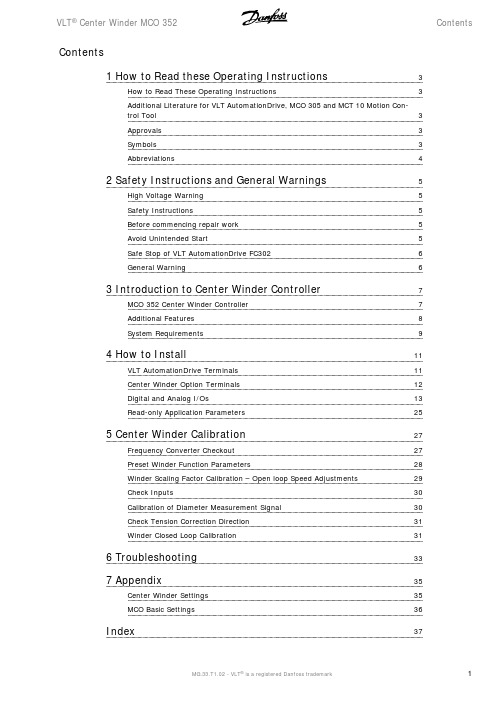
VLT® Center Winder MCO 352Contents Contents1 How to Read these Operating Instructions3How to Read These Operating Instructions3Additional Literature for VLT AutomationDrive, MCO 305 and MCT 10 Motion Con-trol Tool3Approvals3Symbols3Abbreviations42 Safety Instructions and General Warnings5High Voltage Warning5Safety Instructions5Before commencing repair work5Avoid Unintended Start5Safe Stop of VLT AutomationDrive FC3026General Warning63 Introduction to Center Winder Controller7MCO 352 Center Winder Controller7Additional Features8System Requirements94 How to Install11VLT AutomationDrive Terminals11Center Winder Option Terminals12Digital and Analog I/Os13Read-only Application Parameters255 Center Winder Calibration27Frequency Converter Checkout27Preset Winder Function Parameters28Winder Scaling Factor Calibration – Open loop Speed Adjustments29Check Inputs30Calibration of Diameter Measurement Signal30Check Tension Correction Direction31Winder Closed Loop Calibration316 Troubleshooting337 Appendix35Center Winder Settings35MCO Basic Settings36 Index371 How to Read these Operating Instructions VLT® Center Winder MCO 352 111.1.1How to Read These Operating InstructionsThese Operating Instructions will help you get started, program, and troubleshoot your Center Winder Option. Please read these operating instructions in full and, in order to be able to work with the system safely and professionally, particularly observe the hints and cautionary remarks.Chapter How to Read these Operating Instructions introduces the manual and informs you about the approvals, symbols, and abbreviations used in this literature.Chapter Safety Instructions and General Warnings entails instructions on how to handle the Center Winder Controller correctly.Chapter Introduction to Center Winder Controller informs you in general about center winders and different methods of rewinding and unwinding.Chapter How to Install informs you how to start up the Center Winder Option. This section includes the description of the terminals and the parameters.Chapter Center Winder Calibration informs how to calibrate the winder. Detailed instructions on how to proceed can be found in this section.Chapter Troubleshooting assists you in solving problems that may occur when installing and using the Center Winder Controller.Chapter Appendix provides information about parameters in clearly arranged lists. Please see the Parameter Reference in the MCO 305 Design Guide for more details.1.2.1Additional Literature for VLT AutomationDrive, MCO 305 and MCT 10 Motion Control ToolThe MCO 305 Operating Instructions provide the necessary information for build-in, set-up, and optimize the controller.The VLT AutomationDrive FC 300 Operating Instructions provide the necessary information for getting the drive up and running.The VLT AutomationDrive FC 300 Design Guide entails all technical information about the drive and customer design and applications.The VLT AutomationDrive FC 300 MCT 10 Operating Instructions provide information for installation and use of the software on a PC.Danfoss Drives technical literature is also available online at /drives.1.3.1Approvals1.4.1SymbolsSymbols used in this Operating Instructions.NB!Indicates something to be noted by the reader.Indicates a general warning.VLT ® Center Winder MCO 352 1 How to Read these Operating Instructions 1Indicates a high-voltage warning.∗Indicates default setting1.5.1Abbreviations1 How to Read these Operating Instructions VLT ® Center Winder MCO 35212VLT Center Winder MCO352Operating InstructionsSoftware version: 1.xxThese Operating Instructions can be used for the VLT Center Winder MCO352 with all FC 300 frequency converters with software version 4.9x.The software version of FC 300 can be read in parameter 15-43.2.2.1High Voltage WarningThe voltage of the VLT AutomationDrive is dangerous whenever the converter is connected to mains. Incorrect fitting of the motor or the VLT Automa-tionDrive may cause damage to the equipment, serious injury or death. Consequently, it is essential to comply with the instructions in this manual as wellas local and national rules and safety regulations.2.2.2Safety Instructions•Make sure the VLT AutomationDrive is properly connected to earth.•Do not remove mains plugs or motor plugs while the VLT AutomationDrive is connected to mains.•Protect users against supply voltage.•Protect the motor against overloading according to national and local regulations.Motor overload protection is not included in the default settings. To add this function, set par. 1-90 Motor thermal protection to value ETR trip or ETR warning.For the North American market: ETR functions provide class 20 motor overload protection, in accordance with NEC.The earth leakage current exceeds 3.5 mA.The [OFF] key is not a safety switch. It does not disconnect the VLT AutomationDrive from mains.2.2.3Before commencing repair work1.Disconnect VLT AutomationDrive from mains.2.Disconnect DC bus terminals 88 and 89.3.Wait at least 4 minutes.4.Remove motor plugs.2.2.4Avoid Unintended StartWhile VLT AutomationDrive is connected to mains, the motor can be started/stopped using digital commands, bus commands, references or via the LCP. Disconnect the VLT AutomationDrive from mains whenever personal safety considerations make it necessary to avoid unintended start.To avoid unintended start, always activate the [OFF] key before changing parameters. Unless terminal 37 is turned off, an electronic fault, temporary overload, a fault in the mains supply, or lost motor connection may cause a stopped motor to start.VLT® Center Winder MCO 352 2 Safety Instructions and General Warnings22.2.5Safe Stop of VLT AutomationDrive FC302The VLT AutomationDrive FC 302 can perform the Designated Safety Function Uncontrolled Stopping by removal of power (as defined by draft IEC 61800-5-2) or Stop Category 0 (as defined in EN 60204-1). It is designed and approved suitable for the requirements of Safety Category 3 in EN 954-1.This functionality is called Safe Stop. In order to install and use the Safe Stop function in accordance with the requirements of Safety Category 3 in EN 954-1, the related information and instructions of the VLT AutomationDrive FC 300 Design Guide MG.33.BX.YY must be followed! The information and instructions of the Operating Instructions are not sufficient for a correct and safe use of the Safe Stop functionality!2.2.6General Warning2 Safety Instructions and General WarningsVLT ® Center Winder MCO 352233.1.1MCO 352 Center Winder ControllerThe MCO 352 Center Winder Controller uses the speed winder method with a diameter calculation and either a load cell or dancer feedback. Below is a simplified block diagram of a tension controlled winder system. The system would be identical if a dancer were used except that the Taper Function block would have a 0/4-20 mA output used to load the dancer air cylinder proportional to the tapered tension set point. The drive is fed an open loop speed reference based on the calculated diameter of the roll. This signal is summed with a signal generated by a PID amplifier comparing the actual tension feedback with a tapered tension set point. The tapered tension set point is actually the tension set point modified based on the roll diameter and the taper set point. Taper generally reduces the tension set point hyperbolically with a change in diameter. The PID amplifier output is also reduced with increasing diameter since the same change in reference will have a larger surface speed change as the roll increases in diameter. Ideally, the open loop reference signal is scaled at core so that the surface speed of the core matches line speed. The diameter value is calculated by the ratio of line speed verse winder speed.Roll diameter = core diameter (Line speed Winder speed )This calculation needs to be updated fairly quickly since the roll can change diameter very quickly when near the core. If the true diameter changes faster than the diameter is calculated, the open loop reference speed will lag too far behind the required speed and the tension PID will need to make up toomuch of the difference.The Tension PID updates every 30 ms and should be updated at least 3 times faster than the diameter calculation. This is because the tension PID block must be allowed to stabilize system tension before a new diameter is calculated, since the calculated diameter is used by both the open-loop reference and as an input to the tension PID block.VLT ® Center Winder MCO 352 3 Introduction to Center Winder Controller 33.1.2Additional Features Several features have been included to increase the overall stability of the winder and to increase control and monitoring of the winding process.•Acceleration Feed-Forward: The Winder block diagram includes an acceleration feed-forward function that allows a shift in the tension/taper setpoint based on changes in line speed. This provides a tension boost during initial acceleration to help compensate for system inertia.•Tension-Taper Set-Point Ramp: The tapered tension set point generator will integrate any changes to the tension or taper set points over multipleprogram scans. A parameter is provided to increase or decrease response time.•Diameter Calculator Limiter: The diameter calculator includes a similar integration technique. A maximum rate of diameter change can be adjusted by parameter. In addition, the calculated diameter is restricted from moving in the wrong direction to only 20 % of the rate applied to the expected change in diameter. For example, if the station is rewinding a roll, the diameter is not expected to reduce in diameter.•Diameter Calculator Minimum Speed: There is also a minimum speed requirement to enable the diameter calculator. At low speeds, the line andwinder speeds may not have enough resolution to accurately calculate diameter. A parameter is provided to define a minimum line speed required for the diameter calculator to function. Until that speed is reached, the diameter value will not change.•Programmable Analog Inputs: The VLT AutomationDrive has two analog inputs. Inputs 53 and 54 are analog inputs with a voltage range of ±10VDC or a current range of 0/4-20mA. Use DIP-switch S201/S202 to select configuration. The source of the tension and taper set-points can be adjusted by either analog input or parameter setting. The tension feedback and initial diameter measurement can only use analog inputs.Parameters are provided to select the source of each input. Care must be taken not to program a single input for more than one function.•Initial Diameter Measurement: In many winding applications there are very few variations in starting core diameter or initial roll size. A choiceof three programmable starting diameters can be programmed and logically selected. For applications where the starting diameter can vary regularly, the Winder will allow the initial diameter to be measured through an analog input signal. Scaling parameters are provided to set the analog level at core and at full roll. This function assumes a linear change in the diameter measurement signal.•End of Roll Detection: An output is provided to indicate a diameter limit. For rewinding applications, the diameter limit occurs when the calculateddiameter exceeds a set limit. For unwinding applications, the diameter limit occurs when the calculated diameter is less than the set limit. The station will continue to run after a diameter limit is detected. This output can be used to stop the line for a roll change.•Tension Limit Detector: The Winder includes a tension limit detection (TLD) feature. This feature allows the Winder to trip if a low-tension orhigh-tension feedback exists for a period of time. The trip delay includes a normal running delay as well as a secondary starting delay.3 Introduction to Center Winder ControllerVLT ® Center Winder MCO 35233.2.1System RequirementsThe center winder system has some minimum requirements for proper operation.•Frequency converter: VLT AutomationDrive with VLT Center Winder MCO 352. It is also recommended that the drive have dynamic brakingoption capabilities to allow a quick stop of a large roll.•Winder motor: The motor needs to be inverter duty with a wide speed range (>100:1). The motor should be geared or belted so that top motorspeed at core does not exceed 4500 RPM. Generally, the motor maximum constant horsepower speed will be the limiting factor.•Winder Encoder: The winder encoder needs to be mounted on the winder motor. The encoder must have a differential, quadrature TTL/5VDC output. The encoder PPR should be selected such that the channel frequency is as close to 400 kHz at the winder motor top speed.•Line Encoder: The line speed encoder output circuitry needs to be the same as the winder encoder. Again, the encoder PPR should selectedsuch that the channel frequency is as close to 400 kHz at the maximum line speed.•Tension Feedback: The tension feedback is required from either a load cell or dancer. If load cells are used they need to be calibrated for aeither a 0-20 mA or 0-10 V signal from zero to maximum tension. If a dancer is used the calibration should be 0-20mA/0-10V from bottom to top of the dancer movement.•Logic Inputs: The digital inputs for tension on, over/under etc. are 24 VDC, sinking inputs. The drive has a 24VDC/200mA supply available if drycontacts are used. Logic commands can also be sent to the drive serial port. Note that a third party HMI/operator display such as EXOR or Red Lion can be used in place of the digital inputs. It is possible to serially access logic parameters through the VLT AutomationDrive USB or RS485port.•Tension and Taper set-points: The tension and taper set-points are available on the display of the drive as parameters and can also be accessedserially through the VLT AutomationDrive USB or RS485 port. These set points can also be set using any unused 0-20mA/0-10VDC drive input,using an analog signal or potentiometerMaximum Winder Motor speed 4500 RPM Tension Loop Scan Time 30 ms TLD Time Resolution 25 ms Quick Stop Scan time 1 ms Coast Scan Time <1 ms Tension Loop Response Time 25 ms Line encoder frequency 100 kHz - 410 kHz Winder Encoder frequency 100 kHz – 410 kHz Winder Speed resolution ±16384 qc counts @ 4500 RPM Digital inputs 24 VDC, sinking Digital outputs 24 VDC, sourcing Analog Tension & taper set points 0-10 VDC, 0-20 mADC, 1000 count resolution Load cell or dancer feedback 0-10 VDC, 0-20 mADC, 1000 count resolutionVLT ® Center Winder MCO 3523 Introduction to Center Winder Controller34 How to Install VLT® Center Winder MCO 352 444.1.1VLT AutomationDrive TerminalsThe VLT AutomationDrive control card contains input and output logic terminals used by the Winder Option. The Winder Option does not assign a functionto all of the inputs and outputs on the control card. The terminals required for proper Winder operation are discussed in this manual. See the VLT AutomationDrive Operating Instructions for further details.4 53 Multifunction input 154 Multifunction input 255 A/I commonInputs27 Quick Stop37 Safe StopRelay 1Running on tensionRelay 2ReadyAnalog Outputs42 Taper Tension SetpointSupply Voltage50 10 V DC max. load 15 mA4.1.2Center Winder Option TerminalsThe figure below shows the five green terminal strips on the MCO 305 Option Card. The 24V supply on the digital input and output terminal strips areinternally connected to the VLT AutomationDrive +24V supply available at terminals 12 & 13. The COM is connected to VLT AutomationDrive terminal39. An external 24 VDC power supply can be used. See the MCO 305 Instruction Manual for details on setting MCO Supplied by external 24 VDC (parameter33-85). The isolated 5V/400mA and 8V/250mA encoder supply is generated on the MCO 305 Card from the 24 V power supply.is always used for winder/unwinder speedX564is always used for line speedX57 Digital InputsI1 Over/under windingI2 Winder jog reverseI3 Winder jog forwardI4 Partial roll selectI5 Tension on/off (reset)I6 Material selectI7 Core selectI8 Diameter resetX59 Digital OutputsO1 End of roll indicatorO2 TLD indicatorO3 Running on tensionO4 Ready4.2Digital and Analog I/Os4.2.1MCO 352 I/OOption:Function:Determines whether the winder will operate for over or under winding. The motor direction will needto change depending on whether the material is wrapping over or under the winder core. The di-rection selected will also affect the jog directions.NB!This input is scanned only when tension is OFF.Option:Function:Jogs winder in the reverse winding direction at the speed programmed in par. 19-07 (Winder JogSpeed).NB!This input is scanned only when tension is OFF.Option:Function:Jogs winder in Forward winding direction at the speed programmed in par. 19-07 (Winder JogSpeed).NB!This input is scanned only when tension is OFF.Option:Function:Selects new setting in parameter 19-04 as the preset starting diameter when the Diameter Reset(Input 8) is energized, rather than using one of the two preset core diameters. If the initial diameteris to be measured by an analog signal, this input must be held ON along with the correct setting inparameters 19-13 to 19-16.NB!This input is scanned only when tension is OFF.4Option:Function:Turns the tension controller ON and OFF. This input should be energized while the line is at zerospeed. The core will be released when this input is not energized. This input is also used to resetfault conditions.Option:Function:Selects the Material Type (PAPER/POLY). Different material types such as paper verses poly requiredifferent Tension loop PID settings and Speed loop proportional gain settings. Changing this inputtoggles the values in parameters 19-41 to 19-50. If the PID parameter values are changed this inputmust be switch to initiate saving the new values.NB!This input is scanned only when tension is OFF and when the material selection is to be made by digital input (see par. 19-23).Option:Function:Selects one of two preset core sizes set in parameters 19-05 and 19-06. Core 1 = OFF, Core 2 =ON. This input is checked when the Diameter Reset (Input 8) in energized and the partial roll select(Input 4) is not energized. If unwinding, Core 2 can be used as an alternate initial roll diameter, butCore 1 must always be set for the smallest core diameter used.NB!This input is scanned only when tension is OFF.Option:Function:Resets diameter to a new value. If the New Diameter Set (Input 4) is energized, the partial corediameter value set in parameter 19-04 is used, otherwise the diameter is reset to core1 or core2values based on Core Select (Input 7).NB!This input is scanned only when tension is OFF.4.2.2VLT I/OOption:Function:Terminal 27 must be closed for the drive to run. If this input is opened while running, the frequencyconverter will ramp to a stop at a rate set by the Quick Stop Deceleration time (parameter 3-81).4Option:Function:Terminal 37 must be closed for the frequency converter to run. If this input is opened while runningthe frequency converter will coast to a stop.Option:Function:This output turns ON to indicate that the diameter has reached the value programmed in parameter19-12. This output turns OFF when Diameter is reset (Input 8) to a value in normal operating range.Option:Function:This output is turned ON when the Tension Limit Detector has sensed that tension has been out ofrange as set in parameters 19-08 and 19-09 for the number of scans set in parameter 19-10. ATension Limit results in a Winder fault. Turning the tension OFF resets this fault and the output.Option:Function:This output is turned ON when the winder is regulating tension. The output is turned OFF whentension is switched off or if there is a station fault. Turning the tension OFF resets this fault and theoutput.Option:Function:This output is turned ON when the station is ready to run. The output turns OFF if there is a TLDfault, an FC Alarm, an MCO 305 Error, Commanded Quick Stop, or Commanded Coast. Note: Outputs5-8 are not used.Option:Function:This relay output (01, 02, 03) is energized when the winder is regulating tension. The relay outputis de-energized when tension is switched off or if there is a station fault.NB!Parameter 5-40 must be set for MCO controlled [51] for this function to work as described.Option:Function:This relay output (04, 05, 06) is energized when the station is ready to run. The relay will de-energizeon a TLD fault, an FC Alarm, an MCO 305 Error, Quick Stop, or Coast.4NB!Parameter 5-40 must be set for MCO controlled (51) for this function to work as described.4.2.3Analog InputsParameters 19-14, 19-19 to 19-21 allow setting the two analog inputs from the VLT AutomationDrive for any of the following.•Tension Set Point •Taper Set Point •Tension Feedback •Initial Diameter measurement Option:Function:This analog input functions according to the setting of parameter 19-19 to 19-21. Use DIP-switchS201 to select a current (0-20 mA) or a voltage (-10 V to 10 V) configuration.Option:Function:This analog input functions according to the setting of parameter 19-19 – 19-21. Use DIP-switch S201 to select a current (0-20mA) or a voltage (-10 V to 10 V) configuration.Option:Function:This terminal is the common for the two analog inputs 53/54.Option:Function:This terminal is a supply of +10V/30 mA for the analog inputs.Option:Function:When a Dancer system is used, the calculated Tapered Tension Set Point should control the loadingof the dancer air cylinder. This 0/4-20mA output can be used as input for the I-P transducer regu-lating the load on the dancer air cylinder. Parameter 6-50 must be set for either OPTION 0-20 mAor OPTION 4-20 mA.NB!If using a dancer, the Taper set point will have no affect if this output is not used to control the dancer air cylinder.Option:Function:This terminal is used as a common for the analog output signals.44.3.1ParametersOption:Function:Sets the station as either a rewinder or unwinder.[0] *Rewinder[1]UnwinderRange:Function:0 [0-1000]1000 = 100.0% of full tension. Full tension is the point at which the load cell or dancer producesa 20 mA or 10 V signal.Sets the desired running tension. Note that the taper setting will affect the actual tension on theweb. If a dancer system is used, this value sets the dancer running position which would normallybe 500 or center of movement. This parameter is only active if par. 19-19 is set to 0.Range:Function:0 [-1100 – 1100]The Taper set-point is used to change the tension set-point as the diameter increases. The resultof the taper function is called the tapered tension set-point. The tapered tension set-point is alwaysequal to the tension set-point at core. This parameter is only active if parameter 19-20 is set to avalue of 0. A value of 0 = no taper or the tapered tension set-point will always be equal to thetension set-point. A value of 1000 is 100.0 % taper or each time the diameter doubles from corethe tapered tension set-point will be decreased to 50 % of the previous value. Negative tapers arealso possible.NB!Taper is not required in unwinding applications. For unwinding applications, leave this parameter set to 0.19-04 Partial Roll Diameter ValueRange:Function:5000 [5000 – 100000]4This parameter is intended to preset the diameter when a partial roll is loaded on the rewinder. IfInput 4 is ON when the diameter is reset with Input 8, the diameter will be preset to the valueprogrammed in this parameter. For unwinding applications, this parameter can be used to set thefull roll diameter.Range:Function:5000* [5000 – 100000]100000 = 100 % of full roll, see parameter 19-04.This parameter is programmed with the main core value to be used on the winder. This parametermust be set for the smallest core diameter for both rewind and unwind applications.NB!Note: Parameter 19-05 must be less than parameter 19-06.Range:Function:5000* [5000 – 100000]100000 = 100 % of full roll, see Parameter 19-04.This parameter allows programming a secondary core diameter if rewinding or a secondary full rolldiameter if unwinding.NB!Parameter 19-05 must be less than parameter 19-06.Range:Function:0%* [0 – 100%]Winder jog speed 100 = 100 % of the speed set in parameter 3-03 (MAX REFERENCE RPM).This parameter sets the winder jog speed percentage. This speed is used for both forward andreverse jogging. The jog ramp is fixed at 4 seconds.NB!Diameter is not taken into account to determine surface jog speed.Range:Function:0* [-200 – 2000]1000 = 100.0 % tension.This parameter is the low limit for the Tension Limit Detector.NB!Setting the value to -200 will disable the low tension limit trip.4NB!If the tension detection reaches the TLD Low Limit for more than TLD Timer (par. 19-10), output 2 is turned on and a trip is forced. Range:Function:0* [0 – 2200]1000 = 100.0 % tension.This parameter is the high limit for the Tension Limit Detector.NB!Setting the value to 2200 will disable the high tension limit trip.NB!If the tension detection reaches the TLD High Limit for more than TLD Timer (par. 19-10), output 2 is turned on and a trip is forced.Range:Function:1* [1 – 200]Each program scan is approx 25 ms.Sets the number of consecutive program scans that the tension must exceed the high or low tensionlimit before the Tension Limit Output will be energized and the station coasts to a stop. This functionis only active when tension is on.Range:Function:0* [-500 – 0]Each program scan is approx 25 ms.When tension is first turned on, the tension limit timer can be preset to a negative value to allowtime for the winder to stabilize web tension. As soon as the tension moves within the low and hightension limits, the TLD function begins operating normally. This function can be useful during a quickmachine start with a slack web. This function is only active when tension is on.Range:Function:0* [-100 – 100000]100,000 = 100 % of full rollWhen the calculated roll diameter reaches the set diameter, digital output 1 will turn ON to indicatethe end of the roll. This indicates a full roll when rewinding and an empty roll when unwinding.NB!The station will not stop automatically when the end of roll is detected.4Option:Function:It is possible to connect a roll diameter sensor to one of the frequency converter's analog inputs.This signal can be used to have the controller use a measured initial diameter, rather than a diametersize set by parameter. This is particularly useful in applications where non-uniform roll sizes are thenorm.[0] *Set diameter when diameter reset Parameters 19-04 to 19-06 set the diameter when the diameter is reset.[1]Set diameter based on analog signal The frequency converter sets the diameter based on an analog signal. The diameter can only bereset when the tension is OFF.4Option:Function:This parameter sets the analog input used for diameter measurement.[1]Input 53 (0-10 VDC or 0-20 mA)[2]Input 54 (0-10 VDC or 0-20 mA)Range:Function:0* [-1100 – 1100]If a signal of 1.50 V results from measuring the smallest core, set this parameter to 150.This parameter sets the analog input signal reading at the smallest core used. The value needs tobe multiplied by 100 to allow maximum resolution.Range:Function:0 [-1111 – 2111]If a signal of 9.50 V results from measuring the full roll, set this parameter to 950.This parameter sets the analog input signal reading at the largest roll size used. The value needsto be multiplied by 100 to allow maximum resolution.Option:Function:This parameter sets the source of the tension set-point.[0] *Parameter 19-02[1]Input 53 (0-10 VDC or 0-20 mA)[2]Input 54 (0-10 VDC or 0-20 mA)Option:Function:This parameter sets the source of the taper set-point.[0] *Parameter 19-03[1]Input 53 (0-10VDC or 0-20mA)[2]Input 54 (0-10VDC or 0-20mA)Option:Function:Sets analog input used for tension feedback.[1] *Input 53 (0-10 VDC or 0-20 mA)[2]Input 54 (0-10 VDC or 0-20 mA)。
FC300 操作说明书(MG33A143)
VLT® AutomationDrive FC 300
FC 300 操作說明書
目錄
如何閱讀操作說明 ........................................................ 3
認可 ...................................................................... 4 符號 ...................................................................... 5 縮寫 ...................................................................... 5
供透過 DeviceNet Fieldbus 控制、監控和規劃傳動裝置的必要資訊。 - VLT AutomationDrive FC 300 MCT 10 Operating Instructions (VLT AutomationDrive FC 300 MCT 10 作業說明) 提供在電
腦上安裝和使用軟體的資訊。 Danfoss Drives 技術文獻也可在 /drives 網站上找到。 認可
「疑難排解」的分頁符號。
FC 300 300 Operating Instructions (VLT AutomationDrive FC 300 作業說明) 提供啟動和運轉
傳動裝置的必要資訊。 - VLT AutomationDrive FC 300 Design Guide (VLT AutomationDrive FC 300 設計指南) 詳細說明關於傳動裝置及客戶
丹佛斯FC300系列变频器参数讲解
0-03 Regional Settings Value:
* International
[0]
US
[1]
Select International [0] to set par.1-20 Motor Power units to kW and the default value of par. 1-23 Motor Frequency to 50 Hz. Select US [1] to set par.1-21 Motor Power units to HP and the default value of par. 1-23 Motor Frequency to 60 Hz.
Array Number Array Value
0 RPM
0.00 A
1(1)
References
3-1*
References
3-10 Preset Ref. [0] 0,00%
Array Parameter or or
Array Input
0 RPM
0.00 A
1(1)
References
3-1*
vlt?automationdrive1danfossdrivesas2参数表?安装?编程?参数0操作和显示1负载和电机2制动3参考值加减速4限制警告5数字输入输出6模拟输入输出7pid控制器13智能逻辑控制器14特殊功能15变频器信息16数据读出17编码器?警告warning和报警alarm?选件和附件danfossdrivesas3installationmechanicalinstallationdanfossdrivesas4installationmechanicalinstallationdanfossdrivesas5外壳类型mechanicalinstallationdanfossdrivesas6installationelectricalinstallation强电端子?电机端子?电源端子?制动及负载共享?继电器?lc滤波器?外部24v供电danfossdrivesas7installationelectricalinstallationcontrolteminalsdanfossdrivesas8installationelectricalinstallationtensionspringtechnology?接线?拆线?连接danfossdrivesas9installationelectricalinstallationcontrolterminaldiagramdanfossdrivesas10installationelectricalinstallationdanfossdrivesas11installationelectricalinstallation?关开关s201s202ands801开关s201a53s202a54用来选择5354端子的电流020ma或电压输入10to10v开关s801buster
FC-300操作手册19p

经典资料,WORD 文档,可编辑修改,欢迎下载交流。
一、功能简介
1、全程语音提示功能:所有本地或远程操作、报警信息、事件记录查看等都有 语音提示。 2、用户界面:液晶图文显示操作步骤、工作状态、报警流程,使用直观方便。 3、三十二个无线防区:每个无线防区都可自动学习对码,也可通过键盘手动输 入地址编码,本产品主机兼容我公司出品的任何一款无线探测器,便于用户扩充 无线防区。 4、八个有线防区:通过末端电阻配接,实现常开、常闭报警。 5、与其它无线配套产品对码:主机最多可学习八个遥控器、多个无线门铃、任 意个单向无线警号。 6、防区可编程:产品出厂时设置了每个防区的警情类型。用户可根据实际需要 通过编程重新修改防区类型。 7、无线防区对码:无线探测器、遥控器与主机之间采用学习式自动注册或从键 盘手动输入对码, 每个防区/遥控器可分别进行对码或清除对码, 也可整体清除。 8、接警电话号码:可设置 2 个接警中心电话号码和 1 个免费布防号码、1 个免费 撤防号码,4 个普通语音接警电话号码。 9、时钟:内置全自动日历时钟,可与当地时间设置一致。 10、事件记录查询功能:可记录和翻查 120 条不同报警信息的相关内容。如防拆 报警、探测器报警、电话掉线、布防、撤防、电池欠压等发生的时间等,也可查
经典资料,WORD 文档,可编辑修改,欢迎下载交流。
分享一个苹果,各得一个苹果,分享一种思想,各得两种思想。分享是件快乐的事件,乐于分享的人,事业更容易成功。
经典资料,WORD 文档 试 手 册
FC-300 操作说明
经典资料,WORD 文档,可编辑修改,欢迎下载交流。
经典资料,WORD 文档,可编辑修改,欢迎下载交流。
2)依照托架上的螺丝孔位,在墙上打孔,然后将托架固定在墙上。
FC300系列变频器
用量 配置方式
1
外置
1
外置
1
外置
1
外置
1
外置
1
外置
1
外置
1
外置
1
外置
1
外置
1
外置
1
外置
1
外置
1
外置
1
外置
1
外置
制动电阻
规格 用量
100W /150Ω 1 400W/100Ω 1 600W/100Ω 1 800W/100Ω 1 800W/100Ω 1 100W /750Ω 1 100W /750Ω 1 260W/400Ω 1 260W/250Ω 1 260W/200Ω 1 390W/150Ω 1 520W/150Ω 1 780W/100Ω 1 1040W/75Ω 1 1560W/75Ω 1 4800W/40Ω 1
额定 4.0 6.3 8.2 12 14.5
电流 A 输 电压 V 三相 380V±15% 入
频率 50/60Hz
HZ
额定 2.7 4.2 5.5 8.0 9.5
电流 A
电压 V 三相 0-380V 输 出 频 率 0-1000Hz
HZ
过载 200% 立即过流
保护 150%一分钟.
5.5 7.5 11 15 18.5 5.5 7.5 11 15 18.5 19 25 33 46 52
5
第二章 安装和接线
本章为产品的基本“安装和接线”,使用前请仔细阅读本章的注意事项。 2.1 机箱结构和尺寸
FC300 机箱外形图如下:
FC300 塑壳机箱外形图如下: 6
FC300 列变频器的外形尺寸如下表:
变频器型号
安装尺寸 W(mm) H(mm)
FC300 接线及参数设置
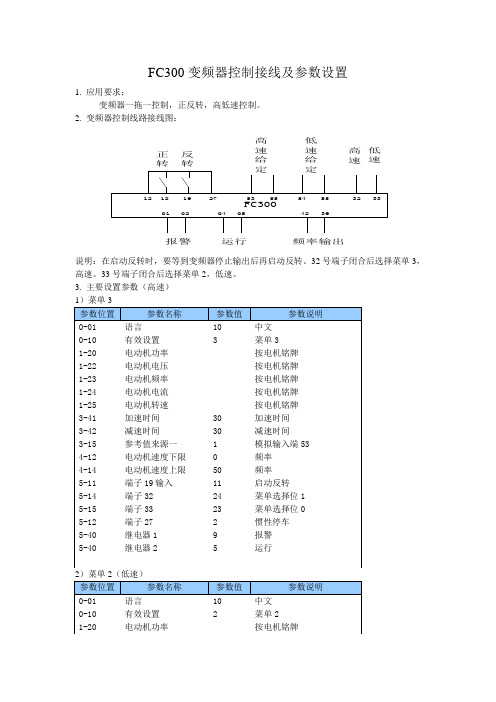
FC300变频器控制接线及参数设置1. 应用要求:变频器一拖一控制,正反转,高低速控制。
2. 变频器控制线路接线图:394201频率输出运行0219275553123332F C 300高速给定正转04报警05185554低速给定反转高速低速说明:在启动反转时,要等到变频器停止输出后再启动反转。
32号端子闭合后选择菜单3,高速。
33号端子闭合后选择菜单2,低速。
3. 主要设置参数(高速)1-22 电动机电压按电机铭牌1-23 电动机频率按电机铭牌1-24 电动机电流按电机铭牌1-25 电动机转速按电机铭牌3-41 加速时间30 加速时间3-42 减速时间30 减速时间3-16 参考值来源2 2 模拟输入端544-12 电动机速度下限0 频率4-14 电动机速度上限50 频率5-11 端子19输入11 启动反转5-14 端子32 24 菜单选择位15-15 端子33 23 菜单选择位05-12 端子27 2 惯性停车5-40 继电器1 9 报警5-40 继电器2 5 运行3)最后把参数0-10的参数设置为9,多重菜单。
4. 要在菜单3,和菜单2里把参数都设置一遍,最后把0-10的参数设置为多重菜单,运行前可闭合32,33号端子,观察一下菜单有无变化,可在面板上看到菜单的变化。
5. 运行时先按一下变频器控制面板的AUTO ON 键,然后才能启动变频器运行。
注:4-10设置为双向,5-11也应改为双向。
另外,由于端子32、33的转换为非无扰切换,所有在菜单的切换过程中会跳转到其他的菜单,比如菜单1,此时就应该在菜单1中也设置5-14和5-15这两个参数。
- 1、下载文档前请自行甄别文档内容的完整性,平台不提供额外的编辑、内容补充、找答案等附加服务。
- 2、"仅部分预览"的文档,不可在线预览部分如存在完整性等问题,可反馈申请退款(可完整预览的文档不适用该条件!)。
- 3、如文档侵犯您的权益,请联系客服反馈,我们会尽快为您处理(人工客服工作时间:9:00-18:30)。
目录
如何阅读这些操作说明 ................................................... 3
认证 ...................................................................... 4 符号 ...................................................................... 5 省略用语 .................................................................. 5
"一般规格"内容的页面标识。
第 6 章,疑难解答,帮助您解决在 FC 300 使用中可能出 现的问题。
"疑难解答"内容的页面标识。
FC 300 的现有资料 - VLT AutomationDrive FC 300 Operating Instructions(VLT AutomationDrive FC 300 操作说明)提供了安装和运行该
第 1 章,如何阅读这些操作说明,简单介绍了本指南,并 且说明了本文中使用的认证、符号和省略用语。
第 2 章,安全说明和一般警告,详细介绍了如何正确操 作 FC 300。
"如何阅读这些操作说明"内容的页面标识。
第 3 章,如何安装,指导您完成机械安装和技术安装。
"安全说明和一般警告"内容的页面标识。
安全说明和一般警告 ...................................................... 7
高压警告 .................................................................. 7 安全说明 .................................................................. 7 避免无意启动 .............................................................. 7
变频器所需要的信息。 - VLT AutomationDrive FC 300 Design Guide(VLT AutomationDrive FC 300 设计指南)详细介绍了有关该变频器和用户设
计以及应用的所有技术信息。 - VLT AutomationDrive FC 300 Profibus Operating Instructions(VLT AutomationDrive FC 300 Profibus 操作说明),
提供了通过 Profibus 现场总线来控制、监测和对该变频器编程的所需信息。 - VLT AutomationDrive FC 300 DeviceNet Operating Instructions(VLT AutomationDrive FC 300 DeviceNet 操作说明),
提供了通过 DeviceNet 现场总线来控制、监测和对该变频器编程的所需信息。 - VLT AutomationDrive FC 300 MCT 10 Operating Instructions(VLT AutomationDrive FC 300 MCT 10 操作说明),提
"如何安装"内容的页面标识
MG.33.A1.41 - VLT 是 Danfoss 的 注 册 商 标
3
FC 300 操作手册
如何阅读这些操作说明
第 4 章,如何编程,介绍了如何通过本地控制面板来操 作 FC 300 以及对其编程。
"如何编程"内容的页面标识。
第 5 章,一般规格,详细介绍了有关 FC 300 的技术数据。
如何编程 ................................................................... 23
本地控制面板 .............................................................. 23 如何在本地控制面板上编程 .................................................. 23 快速传输参数设置 .......................................................... 24 如何将 PC 连接到 FC 300 ........................................................ 25 FC 300软件对话 ............................................................. 26 连接示例 .................................................................. 26 启动/停止 ................................................................. 26 脉冲启动/停止 ............................................................. 26 加速/减速 ................................................................. 26 电位计参照值 .............................................................. 27 两线传感器的连接。 ........................................................ 27 操作和显示 ................................................................ 28 负载和电动机 .............................................................. 29 参照值和极限 .............................................................. 30 参数列表 .................................................................. 31
供了在 PC 上安装和使用该软件的信息。 您也可以通过联机方式从 /drives 获取 Danfoss Drives 技术资料。 认证
警告/报警信息 ............................................................. 51
2
MG.33.A1.41 - VLT 是 Danfoss 的 注 册 商 标
FC 300 操作手册
如何阅读这些操作说明
如何阅读这些操作说明 这些操作说明有助于您迅速了解和安装 VLT AutomationDrive FC 300 以及对它进行编程和疑难解答。 FC 300 提供了两种主轴性能水平。FC 301 提供了从分级速度 (U/f) 到 VVC+ 的性能,而 FC 302 提供了从分级速度 (U/f) 到伺服的性能。 这些操作说明同时涵盖了 FC 301 和 FC 302。在同时适用于两个系列的信息中,我们会使用 FC 300。否则,我们会明 确指出是 FC 301 还是 FC 302。
MG.33.A1.41 - VLT 是 Danfoss 的 注 册 商 标
1
FC 300 操作手册
一般规格 ................................................................... 45 疑难解答 ................................................................... 51
如何安装 ................................................................... 9
如何开始 .................................................................. 9 附件包 ....Байду номын сангаас.................................................................. 10 机械安装 .................................................................. 10 电气安装 .................................................................. 11 连接主电源和接地 .......................................................... 11 电动机连接 ................................................................ 12 电动机电缆 ................................................................ 13 访问控制端子 .............................................................. 14 电气安装,控制端子 ........................................................ 14 MCT 10 设置软件 ............................................................ 15 电气安装,控制电缆 ........................................................ 16 开关 S201、S202 和 S801 ........................................................ 17 紧固力矩 .................................................................. 17 最终设置与测试 ............................................................ 18 其他连接 .................................................................. 19 24 V 备用选件 .............................................................. 19 负载分配 .................................................................. 20 制动连接选件 .............................................................. 20 继电器连接 ................................................................ 21 机械制动控制 .............................................................. 22 电动机热保护 .............................................................. 22
