三星陶瓷电容规格书
低中高压瓷片陶瓷电容器资料规格书
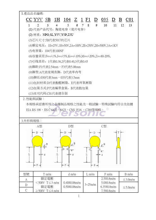
4.0
9.0
5.0 / 7.5
4.0
10.0
5.0 / 7.5
4.0
11.0
5.0 / 7.5
4.0
12.0
5.0 / 7.5
4.0
13.0
5.0 / 7.5
4.0
14.0
5.0 / 7.5
4.0
15.0
5.0 / 7.5
4.0
16.0
5.0 / 7.5
4.0
17.0
5.0 / 7.5
4.0
6.0
5.0 / 7.5
3. Stable capacitance change over the specified temperature.
Product Type
3. ( S - C ) 682PF ~ 224PF measured at 1KHz±10%, 0.1V rms, 25℃
Temp. Range
- 25 ℃ to + 85 ℃
Taping (Radial) -- Lead Spaciபைடு நூலகம்g F = 2.5 / 5.0 / 6.35 / 7.5 ± 0.8
D
s
s
D
H1 Ho
I
P P2
P1
Do Po
b
F
W2 d
W1 Wo w
t
P H1
P2 P1 Ho
Do
I
Po
W2 W1 Wo
s
s
F
d w
t
H1 Ho
I
Straoghe
≦7.0%
≦7.0%
+22% ~ -56% +22% ~ -82%
三星电容规格书

三星电容规格书三星电容规格书是指描述三星电容器性能、特征和使用方法的文档。
该文档的目的是为用户提供关于使用和选择三星电容器的详细信息。
以下是一些常见的参考内容,包括电容器的基本概念、规格、参数、应用建议等。
1. 电容器的基本概念:电容器是一种能够存储电能的被动元件,由两个导体板(电极)和介质组成。
介质可以是电解质、陶瓷、聚合物等。
电容器的主要功能是存储、释放电荷以及滤波和耦合。
2. 电容器的规格说明:规格说明包括电容器的容量、额定电压、尺寸、温度特性等。
容量是电容器存储电荷的能力,通常以法拉(F)为单位。
额定电压是电容器能够承受的最大电压,过高的电压可能导致电容器损坏。
尺寸是指电容器的外观尺寸,通常以长度、宽度和高度表示。
温度特性是指电容器在不同温度下的电容值变化情况。
3. 电容器的参数:电容器的参数包括ESR(等效串联电阻)、ESL(等效串联电感)、Q值、ES(等效串联电阻)、DF(损耗因子)等。
ESR是电容器在交流电路中的等效串联电阻,通常以欧姆(Ω)为单位。
ESL是电容器电极之间的等效串联电感,通常以纳亨(νH)为单位。
Q值是电容器的品质因数,表示其内部损耗的程度。
ES是电容器的等效串联电阻,通常用于表示电容器的交流特性。
DF是电容器的损耗因子,表示电容器内部的能量损耗。
4. 电容器的应用建议:电容器广泛应用于各种电子设备和电路中,如电源管理、通信设备、储存器、调光器、电动机驱动器等。
对于不同的应用场景,选择合适的电容器非常重要。
一般来说,对于高频应用,陶瓷电容器是一个不错的选择;对于高容量和高温度应用,聚合物电容器是一个不错的选择;对于高电压和高频应用,铝电解电容器是一个不错的选择。
以上是关于三星电容器规格书的一些参考内容。
根据具体的产品型号和应用需求,还会有更多详细的规格和参数说明。
在选择和使用电容器时,用户应该仔细阅读和理解规格书,以确保正确选择和合理使用电容器,从而提高电路的性能和可靠性。
三星0603 22uf电容规格书

在这篇文章中,我将会为你撰写一篇有关三星0603 22uf电容规格书的文章。
我会对这个主题进行全面评估,并按照深度和广度的要求展开讨论,以便让你更深入地理解这个话题。
1. 介绍三星0603 22uf电容规格书1.1 什么是三星0603 22uf电容?三星0603 22uf电容是一种电子元件,常用于电子设备的电路中,用于存储电荷和调节电流。
1.2 什么是规格书?规格书是对产品的详细说明和规格参数的文档,用于指导产品的使用和生产。
2. 分析三星0603 22uf电容的规格书2.1 尺寸和外观三星0603 22uf电容的尺寸和外观特征,包括尺寸、形状、外壳材料等。
2.2 电气参数电容的额定电压、容量、误差、温度特性等电气参数的详细规格。
2.3 使用说明三星0603 22uf电容的使用注意事项和建议,以及常见问题和解决方法。
3. 个人观点和理解在这部分,我会共享我个人对三星0603 22uf电容规格书的理解和体会,包括在实际应用中的经验和认识。
总结和回顾部分将对文章进行一个全面、深刻和灵活的总结,以便你能够更全面地了解这个主题。
希望这篇文章能够帮你更深入地理解三星0603 22uf电容规格书,并对其有一个清晰的认识。
文章将符合知识的文章格式,使用序号标注,并在内容中多次提及指定的主题文字。
文章总字数将超过3000字,不包括字数统计。
希望这篇文章能够满足你的需求,让你对三星0603 22uf电容规格书有一个清晰的认识和深入的理解。
三星0603 22uf电容规格书是一份非常重要的文档,它包含了关于这种电容器的详细规格参数以及使用说明。
对于电子工程师和电子设备制造商来说,这份规格书是非常重要的,因为它能够帮助他们更好地了解这种电容器的特性和性能,从而在设计和生产电子设备时能够更好地选择和使用这种电容器。
让我们来介绍一下三星0603 22uf电容。
这种电容器是一种SMD贴片电容器,尺寸为0603,容量为22uf。
三星电容编码识别
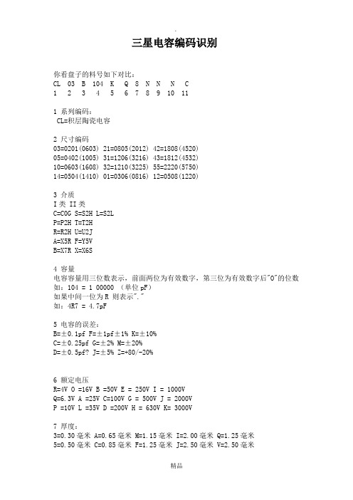
三星电容编码识别你看盘子的料号如下对比:CL 03 B 104 K Q 8 N N N C1 2 3 4 5 6 7 8 9 10 111 系列编码:CL=积层陶瓷电容2 尺寸编码03=0201(0603) 21=0805(2012) 42=1808(4520)05=0402(1005) 31=1206(3216) 43=1812(4532)10=0603(1608) 32=1210(3225) 55=2220(5750)14=0504(1410) 01=0306(0816) 12=0508(1220)3 介质I类 II类C=C0G S=S2H L=S2LP=P2H T=T2HR=R2H U=U2JA=X5R F=Y5VB=X7R X=X6S4 容量电容容量用三位数表示,前面两位为有效数字,第三位为有效数字后"O"的位数如:104 = 1 00000 (单位pF)如果中间一位为R 则表示"."如:4R7 = 4.7pF5 电容的误差:B=±0.1pf F=±1pf±1% K=±10%C=±0.25pf G=±2% M=±20%D=±0.5pf? J=±5% Z=+80/-20%6 额定电压R=4V O =16V B =50V E = 250V I = 1000VQ=6.3V A =25V C=100V G = 500V J = 2000VP =10V L =35V D =200V H = 630V K= 3000V7 厚度:3=0.30毫米 A=0.65毫米 M=1.15毫米 I=2.00毫米 Q=1.25毫米5=0.50毫米 C=0.85毫米 F=1.25毫米 J=2.50毫米 V=2.50毫米8=0.80毫米 D=1.00毫米 H=1.60毫米 L=3.20毫米8 内电极A=常规产品钯/银/镍屏蔽/锡 100%N=常规产品镍/铜/镍屏蔽/锡 100%G=常规产品铜/铜/镍屏蔽/锡 100%L=低侧面产品镍/铜/镍屏蔽/锡 100%9 产品编码A =阵列(2-元素) L =LICCB =阵列(4-元素) N =常规P =自动 C=高频10 特殊编码11 包装编码B=散装 O=纸版箱料带,10英寸料盘 E=压花纸版箱,7英寸料盘P=散装箱 D=纸版箱料带,13英寸料盘(10000ea) F=压花纸版箱,13英寸料盘C=纸版箱料带,7英寸料盘 L=纸版箱料带,13英寸料盘(15,000ea) S=压花纸版箱,10英寸料盘如有侵权请联系告知删除,感谢你们的配合!。
三星规格书(中文版)
ƚƚƚ
7.电容厚度编码:
3 = 0.30 עA = 0.65 עM = 1.15ע 5 = 0.50 עC = 0.85 עF = 1.25ע 8 = 0.80 עD = 1.00 עH = 1.60ע
I = 2.00ע J = 2.50ע L= 3.20ע
July 2006
MUTLAYER CERAMIC CAPACITORS
The specification and designs contained herein may be subject to change without notice.
QS 9000/ISO 9001
Registered by BSI to QS 9000 or ISO 9001 under BSI’s accreditation by UKAS for Certification. Registration NO : FM25309(2002. 2. 28)
6.Low ESL Capacitors
Packaging Specification
67
Reliability Test Condition
71
1.Appearance
2.Insulation Resistance
3.Withstanding Voltage
4.Capacitance
5.Q Factor / Tan Ҝ
Q = 1.25*ע V = 2.50*ע
8.电容内电极 / 端子 / 电镀编码:
A=常规产品 钯/银/镍屏蔽/锡 100% N=常规产品 镍/铜/镍屏蔽/锡 100% G=常规产品 铜/铜/镍屏蔽/锡 100% L=低侧面产品 镍/铜/镍屏蔽/锡 100%
三星钽电容规格书SCS系列
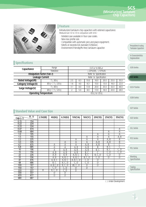
ESR ( ) +25 100KHz Max.
1.2 8.0 6.0 6.0 4.0 3.5 4.0 3.5 4.0 3.5 2.0 3.5 1.8 1.8 1.6 2.0 0.8 1.6 0.8 1.2 0.8 0.5 0.6 0.9 0.7 0.6 8.0 6.0 6.0 4.0 3.5 4.0 3.5 2.0 3.5 2.0 3.0 1.8 2.0 1.3 1.6 3.5 1.2 0.8 0.8 0.8 0.8 1.3 0.9 0.6 0.7 0.5 0.3
Dissipation Factor (Tan ) Leakage Current T 85 Rated Voltage(VR) 85 T 125 Category Voltage(V) Surge Voltage(V)
85 T 85 T 125
SCS Series 25.0 16.0 32.0 20.0 35.0 22.0 44.0 28.0
Precautions in using Tantalum Capacitors 4 Characteristics Explanation
Specifications
Capacitance
Range Tolerance 0.47 to 680 20%(M), 10%(K) Refer to Specification Refer to Specification 16.0 20.0 10.0 10.0 13.0 6.3 20.0 25.0 13.0 13.0 16.0 8.0 -55 to 125 SCN Series
三星电容规格书

三星电容规格书三星电容规格书是指三星集团所生产的电容器产品的详细规格说明书。
下面将为您介绍三星电容规格书中常见的内容。
一、产品介绍三星电容规格书的第一部分是产品的介绍。
这部分通常包括产品名称、型号、外观尺寸、重量等基本信息。
同时,还会介绍产品的应用领域,例如通信设备、电子产品、汽车电子、医疗设备等,并解释为什么该产品适用于该领域。
二、产品特性三星电容规格书的第二部分是产品的特性介绍。
这部分通常包括电容器的电气特性和机械特性。
电气特性包括容量、精度、短时升温性能、稳定性等参数的介绍。
机械特性则包括外观特征、封装形式、连接方式等信息。
此外,还会介绍产品的工作温度范围、湿度条件等环境要求。
三、性能曲线和测试方法三星电容规格书的第三部分是性能曲线和测试方法。
这部分通常会给出电容器在不同工作电压、频率下的电容值曲线图和电阻值曲线图,并解释测试方法和测试条件。
这样用户就可以根据自己的需求选择合适的电容器。
四、质量保证和可靠性三星电容规格书的第四部分是质量保证和可靠性的介绍。
这部分通常包括产品的质量认证情况,如ISO 9001认证、ISO 14001认证等。
同时还会介绍产品的可靠性指标,如寿命、抗震动、抗湿热等性能。
此外,还会介绍三星公司的技术和质量管理体系,以确保产品的可靠性和稳定性。
五、包装和运输三星电容规格书的最后一部分是产品的包装和运输说明。
这部分通常会介绍产品的包装方式、包装材料、包装数量等信息,以及产品的运输方式、运输温度范围等要求。
同时还会提供产品的标签和批次号等信息,方便用户在使用和追溯过程中进行识别。
总结通过三星电容规格书,用户可以了解三星电容器产品的各种规格和性能指标,以便根据自己的需求选择合适的产品。
对于使用三星电容器的客户来说,这份规格书是非常重要的参考资料,它能够帮助用户了解产品的特性、性能以及质量保证等方面的信息,从而使用户能够更好地使用和维护产品。
三星贴片电容规格书08[1]
![三星贴片电容规格书08[1]](https://img.taocdn.com/s3/m/6ed147f0ba0d4a7302763a40.png)
QS 9000/ISO 9001
Registered by BSI to QS 9000 or ISO 9001 under BSI’s accreditation by UKAS for Certification. Registration NO : FM25309(2002. 2. 28) WE WILL PROVIDE A CUSTOMER WITH HIGH RELIABLE PRODUCTS AND SERVICES
�
Asia sales office
Shanghai Office Rm 1408 Shanghai international trade center No 2200 Yan an(W) RD Shanghai China 200335 Te l:86 - 21- 6270 - 4168(274) E-mail:dennis.cha@
Shenzhen Office Rm 4501, 45 /F, New World Center, Yitian Road, Futian District, Shenzhen, China 518026 Te l:86 - 755 - 8608- 5581 E-mail:jackson.xian@ Qingdao Office Rm 1201. Growne Plaza Qingdao; 76XiangGangZhong Rd, Qingdao;266071 P.R. China Te l:86 - 532 - 5779102 E-mail:zhengguo.cui@ HongKong Office Suite 4511, Two int’l Finance Centre, 8 Finance Street, Central, Hongkong Te l:852 - 2862 - 6350 E-mail:vinsent.chou@ Singapore Office 3 Church Street Samsung Hub #23-02 Singapore 049483 Te l: (65)6833 - 3228 E-mail:winson.yeong@ Thai Office Wellgrow Industrial Estate, 93 Moo 5 T. Bangsamak, A.Bangpakong Chachoengsao 24180 Thailand Te l:66 - 38 - 562 - 026 E-mail:sbimm@ Taiwan Office 399 9F - 1, Ruey Kuang Rd., Neihu, Taipei, Taiwan Te l:886 - 2 - 2656 - 8356 E-mail:kevin0130.wang@
三星电容规格书

三星电容规格书1. 引言本规格书旨在介绍三星电容的详细规格和特性。
三星电容是一种高质量、可靠性强的电子元件,广泛应用于各种电路和设备中。
本文将从技术参数、材料特性、封装形式以及应用领域等方面对三星电容进行全面介绍。
2. 技术参数2.1 电容值三星电容提供多种不同的电容值,范围从几皮法到数百微法。
具体的电容值取决于产品型号和系列。
2.2 额定电压每个三星电容都有一个额定电压,表示其能够承受的最大工作电压。
额定电压可以从几伏到数百伏不等。
2.3 容差三星电容的容差指标表明了其实际值与标称值之间的允许偏差范围。
常见的容差包括±5%、±10%等。
2.4 工作温度范围三星电容适用于不同的工作温度范围,常见的工作温度范围包括-40℃至+85℃、-55℃至+125℃等。
2.5 极性部分三星电容是极性电容,需要按照正确的极性连接。
而非极性电容则不受极性限制。
3. 材料特性3.1 介质材料三星电容的介质材料通常采用高质量的聚合物或陶瓷材料。
这些材料具有良好的绝缘性能和稳定性,以确保电容的长期可靠运行。
3.2 极板材料三星电容的极板通常采用优质金属,如铝或钽。
这些金属具有良好的导电性和耐腐蚀性,以确保电容在工作中能够提供稳定可靠的电流传输。
3.3 封装材料三星电容的封装材料通常采用环保型塑料或金属外壳。
这些封装材料具有良好的机械强度和耐高温特性,以保护内部元件并提供稳定的外部连接。
4. 封装形式4.1 表面贴装型(SMD)三星电容可提供表面贴装型封装,方便在PCB上进行自动化焊接。
常见的封装形式有0805、1206、1210等,具体尺寸取决于电容的电容值和额定电压。
4.2 插件型三星电容也可提供插件型封装,适用于手工焊接或特殊应用场景。
插件型封装通常具有引脚,可直接插入PCB或插座中。
5. 应用领域5.1 通信设备三星电容广泛应用于各种通信设备,如手机、无线路由器、基站等。
其高质量和稳定性能确保了通信设备的可靠运行和优秀的信号传输质量。
贴片电容型对照表三星国巨风华选型替代必备
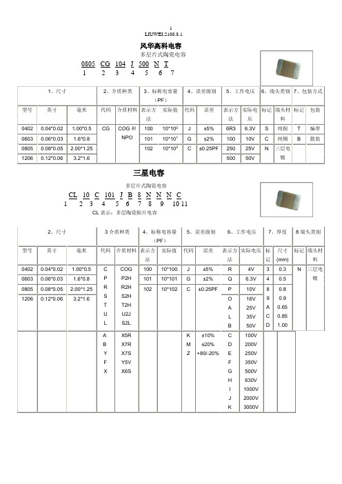
风华高科电容多层片式陶瓷电容0805 CG 104 J 500 N T1 2 3 4 5 6 71、尺寸2、介质种类3、标称电容量(PF)4、误差级别5、工作电压6、端头类别7、包装方式型号英寸毫米代码介质材料表示方法实际值代码误差表示方法实际电压标记端头材料标记包装0402 0.04*0.02 1.00*0.5 CG COG和NPO 100 10*100J ±5% 6R3 6.3V S 纯银T 编带0603 0.06*0.03 1.6*0.8 101 10*101G ±2% 100 10V C 纯铜 B 散装0805 0.08*0.05 2.00*1.25 102 10*102 C ±0.25PF 250 25V N 三层电镀1206 0.12*0.06 3.2*1.6 500 50V三星电容多层片式陶瓷电容CL 10 C 101 J B 8 N N N C1 2 3 4 5 6 7 8 9 10 11CL表示:多层陶瓷贴片电容2、尺寸3介质种类4、标称电容量(PF)5、误差级别6、工作电压7、厚度8端头类别型号英寸毫米代码介质材料表示方法实际值代码误差表示方法实际电压标记尺寸(mm)标记端头材料0402 0.04*0.02 1.00*0.5 CPRSTUL COGP2HR2HS2HT2HU2JS2L100 10*100 J ±5% R 4V 3 0.3 N 三层电镀0603 0.06*0.03 1.6*0.8 101 10*101 G ±2% Q 6.3V 4 0.50805 0.08*0.05 2.00*1.25 102 10*102 C ±0.25PF P 10V 89ACD0.8 0.9 0.650.851.001206 0.12*0.06 3.2*1.6 OALB 16V 25V 35V 50VAB Y F X X5RX7RX7SY5VX6SKMZ±10%±20%+80/-20%CDEFGHIJK100V200V250V350V500V630V1000V2000V3000V国巨(YAGEO)电容多层片式陶瓷电容CC ×××× × ×NPO ×BN ×××1 2 3 4 51、尺寸2、误差精度3、包装形式4、实际电压值5、标称电容量型号英制型号公制代码误差表示方法实际值代码电压代码实际值0201 0603 BCDFGJ±0.1PF±0.25PF±0.5PF±1%±2%±5%R 纸卷盘7inch 7 16V 100 10*1000402 1005 K 吸塑卷盘7inch 8 25V 101 10*101 0603 1608 P 纸卷盘13inch 9 50V 102 10*102 0805 2012 F 吸塑卷盘13inch1206 3216 C 散装1210 32251812 4532TDK贴片电容型号TDK贴片电容的参数识别C 2012 X7R 1H 104 K T系列名称体积材料电压容量误差包装0603=0201 CH 0J=6.3V C=0.25 T=卷带1005=0402 COG 1A=10V D=0.5 B=袋装1608=0603 JB 1C=16V J=5%2012=0805 JF 1E=25V K=10%3216=1206 X7R 1H=50V M=20%3225=1210 X5R 2A=100V Z=+80-20%4532=1812 Y5V 2E=250V5650=2220 2J=630V4520=1808 3A=1KV3D=2KV3F=3KV。
三星电容命名规则
规格说明:CL=积层陶瓷电容03=0201(0603) 21=0805(2012) 42=1808(4520)05=0402(1005) 31=1206(3216) 43=1812(4532)10=0603(1608) 32=1210(3225) 55=2220(5750)14=0504(1410) 01=0306(0816) 12=0508(1220)电容容量用三位数表示,前面两位为有效数字,第三位为有效数字后"O"的位数如:105 = 10 00000 (单位pF)如果中间一位为R 则表示"."如:3R3 = 3.3pFA=常规产品 钯/银/镍屏蔽/锡 100% N=常规产品 镍/铜/镍屏蔽/锡100%G=常规产品 铜/铜/镍屏蔽/锡 100% L=低侧面产品 镍/铜/镍屏蔽/锡 100%A =阵列(2-元素) L =LICCB =阵列(4-元素) N =常规 P =自动 C=高频预留的用途第1页规格事例:I类符号EIA编码工作温度范围(℃)温度系数范围(ppm/℃)C C0G -55~+125 0±30P P2H -55~+125 -150±60R R2H -55~+125 -220±60S S2H -55~+125 -330±60T T2H -55~+125 -470±60U U2J -55~+125 -750±120L S2L -55~+125 -1000~+350II类符号EIA编码工作温度范围(℃)电容变化(?C%)A X5R -55~+85 ±15B X7R -55~+125 ±15X X6S -55~+105 ±22F Y5V -30~+85 -82~+22**系列TC电容步骤***第2页外型尺寸:特征.尺寸的大小从:从0402到2220;.PCB高可靠公差和高速自动芯片更换;.大电容范围;.大温度补偿和电压范围:从COG到Y5V和从6.3V到50V;.高可靠性性能;.高电阻端子金属;.表面贴装组件的带料和料盘尺寸表示图(值见下表)鈀 MLCC(MLCC=A鈀零件编码第12号).I类电容<10pF(I类。
三星SMT电容规格书
■INTRODUCTIONMLCC(Multilayer Ceramic Capacitor)is SMD(Surface Mounted Device)type capacitor that is used in wide ranges of capacitance.MLCC is paid more attentions than other capacitors due to the better frequency characteristics,higher reliability,higher withstanding voltage and so on.MLCC is made of many layers of ceramic and inner electrodes like sandwich.Pd was used for inner electrodes.But the price of Pd was skyrocketed and Pd was replaced by the BME(Base Metal Electrode),which reduced the total cost of MLCC.This inner electrode is connected to outer termination for surface mounting,which is composed of three layers,Cu or Ag layer,Ni plating layer,and SnPb or Sn plating layer.Most of MLCCs become Pb free by the environmental issue at present.MLCC is divided into two classes.Class I(C0G,etc)is the temperature compensating type.It hasa small TCC(Temperature Coefficient of Capacitance)and a better frequency performance.Therefore,it is used in RF applications such as cellular phone,tuner,and so on.Class II(X7R, X5R,Y5V,etc)is the high dielectric constant type,which is used in general electronic circuit.Especially high capacitance MLCC is replacing other capacitors(Tantalum and Aluminum capacitor)due to the low ESR(Equivalent Series Resistance)value.■FEATURE AND APPLICATION●Feature-Miniature Size-Wide Capacitance and Voltage Range-Highly Reliable Performance-Tape&Reel for Surface Mount Assembly-Low ESR-High Q at High Frequencies-Stable Temperature Dependence of Capacitance●Application-High Frequency Circuit(Tuner,VCO,PAM etc)-General Power Supply Circuit(SMPS etc)-DC-DC Converter-General Electronic Circuit■STRUCTURE■APPEARANCE AND DIMENSIONDIMENSION(mm)CODE EIA CODEL W T(MAX)BW 0302010.6±0.030.3±0.030.3±0.030.15±0.05050402 1.0±0.050.5±0.050.5±0.050.2+0.15/-0.1 100603 1.6±0.10.8±0.10.8±0.10.3±0.2210805 2.0±0.1 1.25±0.1 1.25±0.10.5+0.2/-0.3 311206 3.2±0.2 1.6±0.2 1.6±0.20.5+0.2/-0.3 321210 3.2±0.3 2.5±0.2 2.5±0.20.6±0.3431812 4.5±0.4 3.2±0.3 3.2±0.30.8±0.3552220 5.7±0.4 5.0±0.4 3.2±0.3 1.0±0.3■PREVIOUS PART NUMBERINGSymbol EIA Code TemperatureCoefficient(PPM/℃)※TemperatureCharacteristicsOperationTemperature RangeC C0G(CH)0±30C Δ-55~+125℃P P2H -150±60P ΔR R2H -220±60R ΔS S2H -330±60S ΔT T2H -470±60T ΔU U2J -750±120U ΔLS2L+350~-1000SL▶CLASS Ⅰ(Temperature Compensation)TemperatureCharacteristicsbelow 2.0pF 2.2~3.9pF above 4.0pFabove 10pFC ΔC0G C0G C0G C0G P Δ-P2J P2H P2H R Δ-R2J R2H R2H S Δ-S2J S2HS2H T Δ-T2J T2H T2H U Δ-U2JU2JU2JSymbol EIA Code Capacitance Change(ΔC :%)OperationTemperature RangeA X5R ±15-55~+85℃B X7R ±15-55~+125℃FY5V+22~-82-30~+85℃▶CLASS Ⅱ(High Dielectric Constant)SAMSUNG Multilayer Ceramic Capacitor Type(Size)Capacitance Temperature Characteristics Nominal Capacitance Capacitance Tolerance Rated Voltage Thickness Option Packaging Type CAPACITANCE TEMPERATURE CHARACTERISTICS ※Temperature Characteristics ☞K :±250PPM/℃J :±120PPM/℃H :±60PPM/℃G :±30PPM/℃●●●●●●●●●Temperature CharacteristicsSymbol Tolerance Applicable Capacitance &RangeC0G(NPO)or T.C SeriesB ±0.1pF 0.5~3pF C±0.25pF 0.5~10pF D ±0.5pF F ±1pF 6~10pFG ±2%E-24Series for over 10pF J ±5%K±10%A(X5R)B(X7R)J ±5%E-12SeriesK ±10%M ±20%F(Y5V)Z-20%~+80%E-6Series CAPACITANCE TOLERANCE The nominal capacitance value is expressed in pico-Farad(pF)and identified by three-digit number,first two digits represent significant figures and last digit specifies the number of zeros to follow.For values below 1pF,the letter "R"is used as the decimal point and the last digit becomes significant.example)100:10×10o =10pF 102:10×102=1000pF020:2×10o =2pF1R5:1.5pFNOMINAL CAPACITANCE ●●※Please consult us for special tolerances.RATED VOLTAGE ●PACKAGING TYPE THICKNESS OPTION Symbol Description of the CodeN Standard thickness (please refer to standard thickness table on next page)A Thinner than standard thickness B Thicker than standard thicknessC Standard Thickness High Q (Low `D.F `)D Sn-100%(High-Q)ESn-100%(General)※Please Consult us for other termination type.●●Series Capacitance StepE-3 1.02.24.7E-6 1.01.52.23.34.76.8E-12 1.0 1.2 1.5 1.8 2.2 2.7 3.3 3.9 4.7 5.6 6.88.2E-241.0 1.2 1.5 1.82.2 2.73.3 3.94.75.66.88.21.11.31.62.02.43.03.64.35.16.27.59.1※Standard Capacitance is "Each step ×10n "▶STANDARD CAPACITANCE STEP■NEW PART NUMBERING●PRODUCT ABBREVIATION Symbol Product AbbreviationCLSAMSUNG Multilayer Ceramic Capacitor●SIZE(mm)Symbol Size(mm)Length Width 030.60.305 1.00.510 1.60.821 2.0 1.231 3.2 1.632 3.2 2.543 4.5 3.2555.75.0SAMSUNG Multilayer Ceramic Capacitor Size(mm)Capacitance Temperature Characteristic Nominal Capacitance Capacitance Tolerance Rated Voltage Thickness Option Product &Plating Method Samsung Control Code Reserved For Future Use Packaging Type ●●●●●●●●●●●●CAPACITANCE TEMPERATURE CHARACTERISTICSymbol Temperature Characteristics Temperature RangeCClassⅠCOG C△0±30(ppm/℃)-55~+125℃P P2H P△-150±60R R2H R△-220±60S S2H S△-330±60T T2H T△-470±60U U2J U△-750±60L S2L S△+350~-1000AClassⅡX5R X5R±15%-55~+85℃B X7R X7R±15%-55~+125℃F Y5V Y5V+22~-82%-30~+85℃※Temperature CharacteristicTemperatureCharacteristicsBelow2.0pF 2.2~3.9pF Above4.0pF Above10pF CΔC0G C0G C0G C0GPΔ-P2J P2H P2HRΔ-R2J R2H R2HSΔ-S2J S2H S2HTΔ-T2J T2H T2HUΔ-U2J U2J U2JJ:±120PPM/℃,H:±60PPM/℃,G:±30PPM/℃●NOMINAL CAPACITANCENominal capacitance is identified by3digits.The first and second digits identify the first and second significant figures of the capacitance. The third digit identifies the multiplier.'R'identifies a decimal point.●ExampleSymbol Nominal Capacitance1R5 1.5pF10310,000pF,10nF,0.01μF104100,000pF,100nF,0.1μF●CAPACITANCE TOLERANCE Symbol Tolerance Nominal CapacitanceA ±0.05pF Less than 10pF (Including 10pF)B ±0.1pFC ±0.25pFD ±0.5pF F ±1pF F ±1%More than 10pF G ±2%J ±5%K ±10%M ±20%Z+80,-20%●RATEDVOLTAGE●THICKNESS OPTIONType Symbol Thickness(T)Spec 060330.30±0.03 100550.50±0.05 160880.80±0.102012A0.65±0.10 C0.85F 1.25±0.103216C0.85±0.15 F 1.25±0.15 H 1.6±0.203225F 1.25±0.20H 1.6I 2.0J 2.54532F 1.25±0.20H 1.6I 2.0J 2.5L 3.2±0.305750F 1.25±0.20H 1.6I 2.0J 2.5L 3.2±0.30●PRODUCT&PLATING METHODSymbol Electrode Termination Plating TypeA Pd Ag Sn_100%N Ni Cu Sn_100%G Cu Cu Sn_100%●SAMSUNG CONTROL CODE●RESERVED FOR FUTURE USESymbol Description of the codeN Reserved for future use●PACKAGING TYPE▶CAPACITANCE vs CHIP THICKNESS STANDARDDescription0603(0201)1005(0402)1608(0603)2012Type (0805)3216Type (1206)3225Type (1210)4532Type (1812)5750Type (2220)Dimension (mm)L0.6±0.03 1.0±0.05 1.6±0.1 2.0±0.13.2±0.153.2±0.2 3.2±0.34.5±0.45.7±0.4W 0.3±0.030.5±0.050.8±0.1 1.25±0.1 1.6±0.15 1.6±0.22.5±0.23.2±0.3 5.0±0.4T0.3±0.030.5~±0.050.8±0.10.65±0.10.85±0.11.25±0.10.85±0.15 1.25±0.15 1.6±0.21.25±0.2 1.6±0.22.0±0.22.5±0.21.25±0.21.6±0.22.0±0.22.5±0.21.6±0.22.0±0.22.5±0.2C A P ACIT A N CER A N G E (p F )SL 50V -0.5~2400.5~10000.5~10001100~15001600~27000.5~27003000~56006200~8200-----------C,TC (Except SL,UJ)25V 0.5~470.5~2200.5~1000--3300~82001500~36003900~68007500~10000-----100000-----50V -0.5~1800.5~10000.5~560620~10001100~33000.5~22002400~4700-560~1000011000~2200024000~47000-1000~1300015000~2200024000~4700062000~680004300093000130000C A P A C I T A N C E R A N G E (n F )A (X5R)6.3V 102202200--10000--10000---22000---47000--4700010V101001000--2200--4700~10000---22000------4700016V -47330~470--1000--4700---6800~10000-------25V --------------------50V- 6.8~10------------------B (X7R)6.3V 0.1~1047~100470~1000--1000--6800~10000---22000-------10V0.1~1033~100220~470220~270330~470560~1000-1000~330047001500~220033003900~4700----22000---16V0.1~110~33100~22068~200220~330390~1000330~6801000~15002200~33001500~220033003900~4700---2200----25V -4.7~1047~10039~6882~100150~470100~330470~620680~1000680~150018002200---1000---1000050V -0.22~4.70.22~1000.22~3947~1002201~150220390~1000 2.2~680820~1000--10~1000-----3300~4700F (Y5V)6.3V10~100-2200--10000-----47000--------10V -220~330100~1000--4700-470010000~22000---22000------10000016V -10~220100~100010~680820~10001200~22001000~22002700~4700100003300~68001000015000---22000----25V -10~3322~33010~220270~470560~1000470~10001200~22002700~33001000~33004700~10000-----10000---50V - 2.2~102.2~1002.2~6882~150180~100010~470560~1000-100~1000------10000---■PACKAGING●CARDBOARD PAPER TAPESymbol W F E P1P2P0D tABTypeD i m e n s i o n038.0±0.3 3.5±0.05 1.75±0.12.0±0.052.0±0.05 4.0±0.1Φ1.5+0.1/-00.37±0.030.38±0.030.68±0.03050.6±0.050.65+0.05/-0.1 1.15+0.05/-0.110 4.0±0.11.1MAX1.1±0.21.9±0.221 1.6±0.22.4±0.2312.0±0.23.6±0.2unit :mm●EMBOSSED PLASTIC TAPE●TAPING SIZE●REEL DIMENSIONSymbol A B CDEWtR7"Reel φ178±2.0min.φ50φ13±0.521±0.82.0±0.510±1.50.8±0.21.013"Reelφ330±2.0min.φ70unit :mmSymbol Cardboard Paper TapeEmbossed Plastic Tape7"Reel 4000200013"Reel15000-unit :pcsSize 05(0402)10(0603)21(0805)T ≤0.85mm T ≥1.0mm Quantity 50,00010,000~15,000*10,0005,000●BULK CASE PACKAGING-Bulk case packaging can reduce the stock space and transportation costs.-The bulk feeding system can increase the productivity.-It can eliminate the componentsloss.Symbol A B T C D E Dimension 6.8±0.18.8±0.112±0.1 1.5+0.1/-02+0/-0.14.7±0.1Symbol F W G H L I Dimension31.5+0.2/-036+0/-0.219±0.357±0.35110±0.75±0.35●QUANTITY*Option■CHARACTERISTIC MAP●CLASSⅠTemperature Characteristics Size VoltageCapacitance Range(㎊)SL,UJ05 (0402)50V10 (0603)50V21 (0805)50V31 (1206)50VC(COG)& TC Series03(0201)25V05(0402)25V50V10(0603)25V50V21(0805)25V50V31(1206)25V50V 32(1210)50V100V43(1812)25V50V55(2220)50V101001000100001000001000000100000001000000000.5240270082001000100010000150033004700100018022047820033001800047005604700068000100010000013000043000●CLASSⅡ,A(X5R)Temperature Characteristics Size Voltage Capacitance Range(㎊)A(X5R)0603(0201)6.3V10V1005(0402)6.3V10V16V50V1608(0603)6.3V10V16V2012(0805)6.3V10V16V3216(1206)6.3V10V16V3225(1210)6.3V10V16V4532(1812) 6.3V5750(2220)6.3V10V101001000100001000001000000100000001000000001000010000010000100000004700000220000002200000100000004700000220000004700000047000100006800100000022000001000000470000330000100000001000000068000004700000047000000220000●CLASSⅡ,B(X7R)Temperature Characteristics Size VoltageCapacitance Range(㎊)B(X7R)03(0201)6.3V10V16V05(0402)6.3V10V16V25V50V10(0603)6.3V10V16V25V50V21(0805)6.3V10V16V25V50V31(1206)6.3V10V16V 25V50V10100100010000100000100000010000000100000000100000470004700000470000100000100000047000022000010000003300000100000010000001001000010000000100000100000100100001001000680000033000100003300010000470047002204700002200002200001000004700022022000010000006800039000220100000033000010000010000001000●CLASSⅡ,B(X7R)Temperature Characteristics Size VoltageCapacitance Range(㎊)B(X7R)32(1210)6.3V10V16V25V50V43(1812)10V16V25V50V55(2220)25V50V1010010001000010000010000001000000010000000022000000100000010000470000015000002200000010000001000000047000003300000470000015000002200000680000100000022002200000●CLASSⅡ,F(Y5V)Temperature Characteristics Size VoltageCapacitance Range(㎊)F(Y5V)03(0201) 6.3V05(0402)10V16V25V50V10(0603)6.3V10V16V25V50V21(0805)6.3V10V16V25V50V31(1206)10V16V 25V50V32(1210)6.3V10V16V25V50V43(1812)16V25V50V55(2220)10V330000330001000022000010000220010000003300001000001000002200022001000000220000010000100002200000047000001000000033000001000000100000047000010000470000010000001500000033000001000000100000100000002200000010000220000100000001000000010000000022000001000000010000010000100000010000010000002200470000002200000010100100010000100000100000010000000100000000■RELIABILITY TEST DATANO ITEM PERFORMANCE TEST CONDITION 1APPEARANCE NO ABNORMAL EXTERIOR APPEARANCE THROUGH MICROSCOPE(×10)2INSULATIONRESISTANCE10,000㏁OR500㏁∙㎌PRODUCT WHICHEVER ISSMALLER(RATED VOLTAGE IS BELOW16V:10,000㏁OR100㏁∙㎌)RATED VOLTAGE SHALL BE APPLIED.MEASUREMENT TIME IS60~120RATED VOLTAGETIME60SEC.3WITHSTANDINGVOLTAGENO DIELECTRIC BREAKDOWN ORMECHANICAL BREAKDOWNCLASSⅠ:300%OF THE RATED VOLTAGE FOR1~5SEC,CLASSⅡ:250%OF THE RATED VOLTAGE FOR1~5SECIS APPLIED WITH LESS THAN50㎃CURRENT4CAPACITANCECLASSⅠWITHIN THE SPECIFIEDTOLERANCECAPACITANCE FREQUENCY VOLTAGE1,000㎊ANDBELOW1㎒±10%0.5~5VrmsMORE THAN1,000㎊1㎑±10%CLASSⅡWITHIN THE SPECIFIEDTOLERANCECAPACITANCE FREQUENCY VOLTAGE10㎌AND BELOW1㎑±10% 1.0±0.2VrmsMORE THAN10㎌120㎐±20%0.5±0.1Vrms5Q CLASSⅠOVER30㎊:Q≥1,000LESS THAN30㎊:Q≥400+20C(C:CAPACITANCE)CAPACITANCE FREQUENCY VOLTAGE1,000㎊ANDBELOW1㎒±10%0.5~5VrmsMORE THAN1,000㎊1㎑±10%6TanδCLASSⅡ1.CHAR:B2.CHAR:FCAPACITANCE FREQUENCY VOLTAGE10㎌AND BELOW1㎑±10% 1.0±0.2VrmsMORE THAN10㎌120㎐±20%0.5±0.1Vrms RATED VOLTAGE DF SPEC6.3V0.05max10V0.05max16V0.035max25V0.025max50V이상0.025max6.3V10V16V25V50V1005-0.125max0.09max(C<220nF)0.125max(C≥220nF)0.05max0.05max16080.16max0.125max0.09max0.05max(C≤100nF)0.07max(C>100nF)0.05max20120.16max0.125max0.09max0.07max0.05max32160.16max0.125max0.09max0.07max0.05max32250.16max0.125max0.09max0.07max(C≤6.8㎌)0.09max(C>6.8㎌)0.05max45320.16max0.16max0.09max--57500.125max---*THE INITIAL VALUE OF HIGH DIELECTRIC CONSTANT SERIES SHALL BE MEASUREDAFTER THE HEAT TREATMENT OF150+0/-10℃,1Hr AND SITTING OF48±4hr AT ROOM TEMPERATURE&ROOM HUMIDITY.NO ITEM PERFORMANCE TEST CONDITION14HUMIDITY(STEADYSTATE)APPEARANCE NO MECHANICAL DAMAGE SHALL OCCUR TEMPERATURE:40±2℃RELATIVE HUMIDITY:90~95%RHTEST TIME:500+12/-0Hr.MEASURE AT ROOM TEMPERATUREAFTER COOLING FORCLASSⅠ:24±2Hr.CLASSⅡ:48±4Hr.CAPACITANCECHARACTERISTIC CAPACITANCE CHANGECLASSⅠWITHIN±5%OR±0.5㎊WHICHEVERIS LARGERCLASSⅡA,B WITHIN±12.5%F WITHIN±30%QCLASSⅠ30㎊AND OVER:Q≥35010~30㎊:Q≥275+2.5×CLESS THAN10pF:Q≥200+10×CTanδCLASSⅡINSULATIONRESISTANCEMINIMUM INSULATION RESISTANCE:1,000㏁OR50㏁∙㎌PRODUCT WHICHEVER ISSMALLER15MOISTURERESISTANCEAPPEARANCE NO MECHANICAL DAMAGE SHALL OCCUR APPLIED VOLTAGE:RATED VOLTAGETEMPERATURE:40±2℃RELATIVE HUMIDITY:90~95%RHTEST TIME:500+12/-0Hr.CURRENT APPLIED:50㎃MAX.<INITIAL MEASUREMENT>CLASSⅡSHOULD BE MEASUREDINITIAL VALUE AFTER BE HEAT-TREATEDFOR1HR IN150℃+0/-10℃AND BE LEFTFOR48±4HR AT ROOM TEMPERATURE.<LATTER MEASUREMENT>CLASSⅠSHOULD BE MEASURED AFTERLEFT FOR24±2HRS IN ROOMTEMPERATURE AND HUMIDITY.CLASSⅡSHOULD BE MEASUREDLATTER VALUE AFTER BEHEAT-TREATED FOR1HR IN150℃+0/-10℃AND BE LEFT FOR48±4HR AT ROOMTEMPERATURE.CAPACITANCECHARACTERISTIC CAPACITANCE CHANGECLASSⅠWITHIN±7.5%OR±0.75㎊WHICHEVERIS LARGERCLASSⅡA,B WITHIN±12.5%FWITHIN±30%WITHIN+30~-40%1005C>0.47μF1608C>1.0μF2012C>4.7μF3216C>10.0μF3225C>22.0μF4532C>47.0μFQCLASSⅠ30㎊AND OVER:Q≥20030㎊AND BELOW:Q≥100+10/3×CTanδCLASSⅡINSULATIONRESISTANCEMINIMUM INSULATION RESISTANCE:500㏁OR25㏁∙㎌PRODUCT,WHICHEVER IS SMALLER.CHAR.25VANDOVER16V10V 6.3V4VA,B0.050.05MAX0.05MAX0.075MAX0.1MAXF0.075MAX0.1MAX(C〈1.0㎌)0.125MAX(C≥1.0㎌)0.15MAX0.195MAX0.25MAXCHAR.25VANDOVER16V10V 6.3V4VA,B0.05MAX0.05MAX0.05MAX0.075MAX0.1MAXF0.075MAX0.1MAX(C〈1.0㎌)0.125MAX(C≥1.0㎌)0.15MAX0.195MAX0.25MAX6.3VTanδ0.125MAX*ConditionCLASSⅡ(A,B)1005C≥0.22㎌1608C≥2.2㎌2012C≥4.7㎌3216C≥10.0㎌3225C≥22.0㎌4532C≥47.0㎌5750C≥100.0㎌6.3V Tanδ0.125MAX*ConditionCLASSⅡ(A,B)1005C≥0.22㎌1608C≥2.2㎌2012C≥4.7㎌3216C≥10.0㎌3225C≥22.0㎌4532C≥47.0㎌5750C≥100.0㎌NO ITEM PERFORMANCE TEST CONDITION16HIGHTEMPERATURERESISTANCEAPPEARANCE NO MECHANICAL DAMAGE SHALL OCCURAPPLIED VOLTAGE:150%,200%OF RATED VOLTAGETEST TIME:1000+48/-0Hr.CURRENT APPLIED:50㎃MAX.<INITIAL MEASUREMENT>CLASSⅡSHOULD BE MEASURED INITIALVALUE AFTER BE HEAT-TREATED FOR1HR IN150℃+0/-10℃AND BE LEFT FOR48±4HR AT ROOM TEMPERATURE.<LATTER MEASUREMENT>CLASSⅠSHOULD BE MEASURED AFTERLEFT FOR24±2HRS IN ROOMTEMPERATURE AND HUMIDITY.CLASSⅡSHOULD BE MEASURED LATTERVALUE AFTER BE HEAT-TREATED FOR1HR IN150℃+0/-10℃AND BE LEFT FOR48±4HR AT ROOM TEMPERATURE.(TWICE OF RATED VOLTAGE WILL BEAPPLIED TO ALL SERIES BUT ABOVE)**HOWEVER,A/B는1005C≥0.22㎌SEE(FIG.3)CAPACITANCECHARACTERISTIC CAP.CHANGECLASSⅠWITHIN±3%OR±0.3㎊,WHICHEVER IS LARGERCLASSⅡA,B WITHIN±12.5%FWITHIN±30%WITHIN+30~40%1005C>0.47μF1608C>1.0μF2012C>4.7μF3216C>10.0μF3225C>22.0μF4532C>47.0μFQCLASSⅠ30㎊AND OVER:Q≥35010~30㎊:Q≥275+2.5×CLESS THAN10㎊:Q≥200+10×CTanδCLASSⅡINSULATIONRESISTANCEMINIMUM INSULATION RESISTANCE:1,000㏁OR50㏁∙㎌PRODUCTWHICHEVER IS SMALLER17TEMPERATURECYCLEAPPEARANCE NO MECHANICAL DAMAGE SHALL OCCUR CAPACITORS SHALL BE SUBJECTEDTO FIVE CYCLES OF THETEMPERATURE CYCLE AS FOLLOWINGSTEP TEMP.(℃)TIME(MIN)1MIN.RATEDTEMP.+0/-3302252~33MAX.RATEDTEMP.+3/-0304252~3MEASURE AT ROOM TEMPERATUREAFTER COOLING FORCLASSⅠ:24±2Hr.CLASSⅡ:48±4Hr.CAPACITANCECHARACTERISTIC CAP.CHANGECLASSⅠWITHIN±2.5%OR±0.25㎊WHICHEVER ISLARGERCLASSⅡA,B WITHIN±7.5%F WITHIN±20%QCLASSⅠ30㎊AND OVER:Q≥1000LESS THAN30㎊:Q≥400+20×CTanδCLASSⅡTO SATISFY THE SPECIFIEDINITIAL VALUEINSULATIONRESISTANCETO SATISFY THE SPECIFIEDINITIAL VALUECHAR.25VANDOVER16V10V 6.3V4VA,B0.05MAX0.05MAX0.05MAX0.075MAX0.1MAXF0.075MAX0.1MAX(C<1.0㎌)0.125MAX(C≥1.0㎌)0.15MAX0.195MAX0.25MAXCHAR.TEMP.CLASSⅠ125±3℃CLASSⅡA85±3℃B125±3℃F85±3℃*150%Authorization ConditionsCLASSⅡ(A,B,F)1005C>0.47μF1608C≥2.2㎌2012C≥4.7㎌3216C≥10.0㎌3225C≥22.0㎌4532C≥47.0㎌5750C≥100.0㎌■CHARACTERISTIC GRAPH▶CAPACITANCE CHANGE -AGING▶CAPACITANCE -DC VOLTAGE CHARACTERISTICS▶CAPACITANCE -TEMPERATURE CHARACTERISTICS●ELECTRICAL CHARACTERISTICS■APPLICATION MANUAL●Storage Condition▶Storage EnvironmentThe electrical characteristics of MLCCs were degraded by the environment of high temperature or humidity.Therefore,the MLCCs shall be stored in the ambient temperature and the relative humidity of less than40℃and70%,respectively.Guaranteed storage period is within6months from the outgoing date of delivery.▶Corrosive GasesSince the solderability of the end termination in MLCC was degraded by a chemical atmosphere such as chlorine,acid or sulfide gases,MLCCs must be avoid from these gases.▶Temperature FluctuationsSince dew condensation may occur by the differences in temperature when the MLCCs are taken out of storage,it is important to maintain the temperature-controlled environment.●Design of Land PatternWhen designing printed circuit boards,the shape and size of the lands must allow for theproper amount of solder on the capacitor.The amount of solder at the end terminations has a direct effect on the crack.The crack in MLCC will be easily occurred by the tensile stress which was due to too much amount of solder.In contrast,if too little solder is applied,the termination strength will be e the following illustrations as guidelines for proper land design.Recommendation of Land Shape and Size●AdhesivesWhen flow soldering the MLCCs,apply the adhesive in accordance with the following conditions.▶Requirements for AdhesivesThey must have enough adhesion,so that,the chips will not fall off or move during thehandling of the circuit board.They must maintain their adhesive strength when exposed to soldering temperature.They should not spread or run when applied to the circuit board.They should harden quickly.They should not corrode the circuit board or chip material.They should be a good insulator.They should be non-toxic,and not produce harmful gases,nor be harmful when touched.▶Application MethodIt is important to use the proper amount of adhesive.Too little and much adhesive will cause poor adhesion and overflow into the land,respectively.▶Adhesive hardening CharacteristicsTo prevent oxidation of the terminations,the adhesive must harden at160℃or less,within2minutes or less.●Mounting▶Mounting Head PressureExcessive pressure will cause crack to MLCCs.The pressure of nozzle will be300g maximum during mounting.▶Bending StressWhen double-sided circuit boards are used,MLCCs first are mounted and soldered onto one side of the board.When the MLCCs are mounted onto the other side,it is important to support the board as shown in the illustration.If the circuit board is not supported,the crack occur to the ready-installed MLCCs by the bending stress.●FluxAlthough the solderability increased by the highly-activated flux,increase of activity in flux may also degrade the insulation of the chip capacitors.To avoid such degradation,it is recommended that a mildly activated rosin flux(less than0.2%chlorine)be used.●SolderingSince a multilayer ceramic chip capacitor comes into direct contact with melted solder during soldering,it is exposed to potentially mechanical stress caused by the sudden temperature change.The capacitor may also be subject to silver migration,and to contamination by the flux.Because of these factors,soldering technique is critical.▶Soldering MethodsMethodClassificationReflow soldering-Overall heating-Infrared rays -Hot plate-VPS(vapor phase)-Local heating-Air heater -Laser-Light beamFlow soldering-Single wave -Double wave-*We recommend the reflow soldering method.▶Soldering ProfileTo avoid crack problem by sudden temperature change,follow the temperature profile in the adjacentgraph.30025020015010050℃Reflow Soldering 30025020015010050℃60~120sec 3~4secFlow Soldering▶Manual SolderingManual soldering can pose a great risk of creating thermal cracks in chip capacitors.The hotsoldering iron tip comes into direct contact with the end terminations,and operator's carelessnessmay cause the tip of the soldering iron to come into direct contact with the ceramic body of the capacitor.Therefore the soldering iron must be handled carefully,and close attention must be paid to the selection of the soldering iron tip and to temperature control of the tip.▶Amount ofSolder▶CoolingNatural cooling using air is recommended.If the chips are dipped into solvent for cleaning, the temperature difference(△T)must be less than100℃6-6.CleaningIf rosin flux is used,cleaning usually is unnecessary.When strongly activated flux is used, chlorine in the flux may dissolve into some types of cleaning fluids,thereby affecting the chip capacitors.This means that the cleaning fluid must be carefully selected,and should always be new.▶Notes for Separating Multiple,Shared PC Boards.A multi-PC board is separated into many individual circuit boards after soldering has been completed.If the board is bent or distorted at the time of separation,cracks may occur in the chip capacitors.Carefully choose a separation method that minimizes the bending of the circuit board.■CROSS REFERENCEP/N COMPANY SAMSUNG AVX JOHANSON KEMET KYOCERA MURATA NOVACAP PANASONIC ROHMTAIYO-YUDENTDK VITRAMON①COMPANY MODEL(MLCC)CL--C CM GRM-ECJ MCH MK C VJ②SIZE (EIA/JIS)0201(0603)03---0333-Z-0630603-0402(1005)050402R0704020536040201510510050402 0603(1608)100603R14060310539060311810716080603 0805(2012)210805R1508052140080522121220120805 1206(3216)311206R181********-6120633131632161206 1210(3225)321210S4112103242-2121043232532251210 1808(4520)421808R29180842-1808---45201808 1812(4532)431812S4318124343-21812-4343245321812 2220(5750)55--22205544-12221--5505650-③TEMPERATURE CHARACTERISTIC COG(NPO)C A N G CG COG/CH N C A C COG/CH A P2H(N150)P S--P P2H-P-P PH-R2H(N220)R1--R R2H-R-R RH-S2H(N330)S3--S S2H-S-S SH-T2H(N470)T O--T T2H-T-T TH-U2J(N750)U Z--U U2J-U UJ U UJ-S2L L Y--SL SL-G SL SL SL-X7R B C W R(X)X7R X7R B B C BJ X7R(B)Y(X) Z5U E E Z U-Z5U Z-E-Z5U U Y5V F G Y V Y5V Y5V Y F F F Y5V-④NOMINAL CAPACITANCE EX)103=10,000㎊221=220㎊225=2,200,000㎊=2.2㎌1R5=1.5㎊010=1㎊⑤CAPACITANCE TOLERANCE B:±0.1㎊C:±0.25㎊D:±0.5㎊F:±1%G:±2%J:±5%K:±10%M:±20%Z:-20~+80%⑥RATED VOLTAGE6.3V Q6-906 6.3-0J-J0J-10V P Z10081010-1A4L1A-16V O Y160416161601C3E1C J 25V A3250325252501E2T1E X 50V B5500550505001H5U1H A 100V C110111*********A1-2A B 200V D220122002002012D---C 250V E V--250250251---2E-500V G7501-500500501----E 630V H---630630----2J-1000V I A102-10001K102---3A G 2000V J G202-20002K202---3D-3000V K H302-30003K302---3F H 4000V-J-4000-402-----⑦TERMINATIONNICKEL BARRIER N T V C A(GRM)N-(MCH)--X Ag/Pd P1--B(GR)P-(MC)--F⑧PACKAGEBULK(VINYL)B9(NONE)-B PB*X-B B B PAPER TAPING C2,4T,R-T,L PT T E,V,W K,L T T C,P PLASTIC TAPING E1,3E,U-H,N PT-F,Y P,Q T-T,R BULK CASE P7--C PC-C C--G。
贴片电容型对照表三星国巨风华选型替代必备

贴片电容型对照表三星国巨风华选型替代必备 SANY标准化小组 #QS8QHH-HHGX8Q8-GNHHJ8-HHMHGN#风华高科电容多层片式陶瓷电容0805CG104J500NT 1 23 4 5 6 71、尺寸2、介质种类3、标称电容量(PF )4、误差级别5、工作电压6、端头类别7、包装方式型号 英寸 毫米 代码 介质材料 表示方法实际值 代码 误差表示方法 实际电压 标记 端头材料标记 包装 0402 * * CG COG 和NPO 100 10*100J ±5%6R3 S 纯银 T 编带0603 * * 101 10*101G ±2%100 10V C 纯铜 B 散装0805 * * 102 10*102C ±250 25V N 三层电镀 1206**500 50V三星电容多层片式陶瓷电容CL10C101JB8NNNC 1 234 5 6 7 8 9 10 11CL 表示:多层陶瓷贴片电容2、尺寸3介质种类4、标称电容量(PF )5、误差级别6、工作电压7、厚度8端头类别型号 英寸 毫米 代码 介质材料 表示方法实际值 代码 误差表示方法 实际电压 标记 尺寸(mm) 标记 端头材料 0402 * * C P R S T U L COG P2H R2H S2H T2H U2J S2L 100 10*100 J ±5% R 4V 3N 三层电镀 0603 * * 101 10*101 G ±2% Q 40805 * * 102 10*102 C ± P 10V 89 A C D1206**O A L B 16V25V35V50VA ?B ? Y F XX5R X7R X7S Y5V X6SK M Z±10% ±20% +80/-20% C D E F G H I J K 100V200V 250V350V 500V 630V 1000V 2000V 3000V多层片式陶瓷电容CC ×××××× NPO × BN ×××123 45TDK型号TDK贴片电容的参数识别C 2012 X7R 1H 104 K T系列名称体积材料电压容量误差包装0603=0201 CH 0J= C= T=卷带1005=0402 COG 1A=10V D= B=袋装1608=0603 JB 1C=16V J=5%2012=0805 JF 1E=25V K=10%3216=1206 X7R 1H=50V M=20%3225=1210 X5R 2A=100V Z=+80-20% 4532=1812 Y5V 2E=250V5650=2220 2J=630V4520=1808 3A=1KV3D=2KV3F=3KV。
三星电子多层陶瓷电容商品说明书

● Supplier : Samsung Electro-Mechanics CL10B103KA8WPNC● Product : Multi-layer Ceramic CapacitorCAP, 10㎋, 25V, ± 10%, X7R, 0603● AEC-Q200 QualifiedA. Dimension● DimensionB. Samsung Part NumberCL 10B K A 8W P N C ①②③⑤⑥⑦⑧⑨⑩⑪①Series Samsung Multi-layer Ceramic Capacitor ②Size (inch code)L :1.60±0.10 mm W :0.80±0.10 mm ③Dielectric ⑧Inner electrode Ni, Open Mode Design ④Capacitance ㎋Termination Metal-Epoxy ⑤Capacitance ± 10%Plating Sn 100% (Pb Free)tolerance ⑨Product Automotive ⑥Rated Voltage V⑩Special code Normal⑦Thickness0.80±0.10 mm⑪PackagingCardboard Type, 7" ReelTest items High Temperature Appearance : No abnormal exterior appearance Unpowered,1,**********************ExposureCapacitance Change Within ±10 %Measurement at 24±2hrs after test conclusion Tan δ :0.03 max.IR :More than 10,000 ㏁ or 500 ㏁×㎌Initial Measurement 2* Whichever is smallerFinal Measurement 3*Temperature Cycling Appearance : No abnormal exterior appearance1,000CyclesCapacitance Change Within ±10 %Initial Measurement 2* Tan δ :0.03 max.Final Measurement 3*IR :More than 10,000 ㏁ or 500 ㏁×㎌Measurement at 24±2hrs after test conclusionWhichever is smaller1 cycle condition : -55+0/-3℃(30±3min) → Room Temp. (1min)→ 125+3/-0℃(30±3min) → Room Temp. (1min)Destructive Physical No Defects or abnormalities Per EIA 469Analysis Humidity BiasAppearance : No abnormal exterior appearance 1,000hrs 85℃/85%RH, Rated Voltage and 1.3~1.5V,Capacitance Change Within ±12.5 %Add 100kohm resistor Tan δ :0.035 max.Initial Measurement 2* IR :More than 500 ㏁ or 25 ㏁×㎌Final Measurement 4*Whichever is smallerMeasurement at 24±2hrs after test conclusion The charge/discharge current is less than 50mA.High Temperature Appearance : No abnormal exterior appearance 1,000hrs @ 125℃, 200% Rated Voltage,Operating LifeCapacitance Change Within ±12.5 %Initial Measurement 2* Tan δ :0.035 max.Final Measurement 4*IR :More than 1,000 ㏁ or 50 ㏁×㎌Measurement at 24±2hrs after test conclusion Whichever is smallerThe charge/discharge current is less than 50mA.Specification of Automotive MLCC (Reference sheet)103L W T ● Samsung P/N :● Description :0.30±0.20 mmBWSize 0603 inch 1.60±0.10 mm 0.80±0.10 mm 0.80±0.10 mm X7R PerformanceTest condition25④060310External VisualNo abnormal exterior appearance Microscope (´10)Physical Dimensions Within the specified dimensions Using The calipersMechanical ShockAppearance : No abnormal exterior appearance Three shocks in each direction should be applied along Capacitance Change Within ±10 % 3 mutually perpendicular axes of the test specimen (18 shocks)Tan δ, IR :Initial spec.Initial Measurement 2* Final Measurement 5*VibrationAppearance : No abnormal exterior appearance 5g's for 20min., 12cycles each of 3 orientations,Capacitance Change Within ±10 %Use 8"×5" PCB 0.031" Thick 7 secure points on one long side Tan δ, IR :Initial spec.and 2 secure points at corners of opposite sides. Parts mounted within 2" from any secure point. Test from 10~2,000㎐.Initial Measurement 2* Final Measurement 5*Resistance to Appearance : No abnormal exterior appearance preheating : 150℃ for 60~120 sec.Solder HeatCapacitance Change Within ±10 %Solder pot : 260±5℃, 10±1sec.Tan δ, IR :Initial spec.Initial Measurement 2* Final Measurement 3*ESDAppearance : No abnormal exterior appearance AEC-Q200-002 or ISO/DIS10605Capacitance Change Within ±10 %Initial Measurement 2* Tan δ, IR :Initial spec.Final Measurement 4*Solderability95% of the terminations is to be soldered a) Preheat at 155℃ for 4 hours, Immerse in solder for 5s at 245±5℃evenly and continuouslyb) Steam aging for 8 hours, Immerse in solder for 5s at 245±5℃c) Steam aging for 8 hours, Immerse in solder for 120s at 260±5℃solder : a solution ethanol and rosinElectrical Capacitance : Within specified tolerance *A capacitor prior to measuring the capacitance is heat treated at CharacterizationTan δ :0.025 max.150 +0/-10℃ for 1hour and maintained in ambient air for 24±2 hours IR(25℃) :More than 10,000 ㏁ or 500 ㏁×㎌The Capacitance / D.F. should be measured at 25℃,Whichever is smaller1 ㎑ ± 10%,1 ± 0.2 VrmsIR(125℃) More than 1,000 ㏁ or 10 ㏁×㎌I.R. should be measured with a DC voltage not exceeding Whichever is smallerRated Voltage @25℃, @125℃ for 60~120 sec.Dielectric StrengthDielectric Strength : 250% of the rated voltage for 1~5 seconds Board FlexAppearance : No abnormal exterior appearance Bending to the limit,3 ㎜ for 60 seconds 1*Capacitance Change Within ±10 %Initial Measurement 2*Final Measurement 5*Terminal Appearance : No abnormal exterior appearance 10 N, for 60 sec.Strength(SMD)Capacitance Change Within ±10 %Initial Measurement 2* Final Measurement 5*Beam Load Destruction value should be exceed 20 NBeam speed :0.5±0.05 ㎜/secTemperature X7RCharacteristicsFrom -55 ℃ to 125 ℃, Capacitance change should be within ±15%Reflow ( Reflow Peak Temperature : 260 +0/-5℃, 30sec. ), Meet IPC/JEDEC J-STD-020 D Standard*1 : The figure indicates typical specification. Please refer to individual specifications.*2 : Initial measurement : Perform a heat treatment at 150 +0/-10℃ for one hour after soldering process. and then let sit for 24±2 hours at room temperature. Perform the initial measurement.*3 : Final measurement : Let sit for 24±2 hours at room temperature after test conclusion, then measure.*4 : Final measurement : Perform a heat treatment at 150 +0/-10℃ for one hour after soldering process. and then let sit for 24±2 hours at room temperature. Perform the initial measurement.*5 : Final measurement : Let measure within 24 hours at room temperature after test conclusion.Product specifications included in the specifications are effective as of March 1, 2013. Please be advised that they are standard product specifications for reference only.We may change, modify or discontinue the product specifications without notice at any time. So, you need to approve the product specifications before placing an order.Should you have any question regarding the product specifications, please contact our sales personnel or application engineers.0.5msHalf sine4.7m/secPerformance Test conditionPeak value Duration Wave Velocity 1,500G● Disclaimer & Limitation of Use and ApplicationThe products listed in this Specification sheet are NOT designed and manufactured for any use and applications set forth below.Please note that any misuse of the products deviating from products specifications or information provided in this Spec sheet may cause serious property damages or personal injury.We will NOT be liable for any damages resulting from any misuse of the products, specifically including using the products for high reliability applications as listed below.If you have any questions regarding this 'Limitation of Use and Application', you should first contact our sales personnel or application engineers.① Aerospace/Aviation equipment② Medical equipment③ Military equipment④ Disaster prevention/crime prevention equipment⑤ Power plant control equipment⑥ Atomic energy-related equipment⑦ Undersea equipment⑧ Traffic signal equipment⑨ Data-processing equipment⑩ Electric heating apparatus, burning equipment⑪ Safety equipment⑫ Any other applications with the same as or similar complexity or reliability to the applications。
CL03A104KQ3NNNC中文资料
物料编号:CL03A104KQ3NNNC的详细参数_易容网
MLCC即是多层陶瓷电容片式,是电子信息产品不可或缺的基本组件之一。
我国MLCC的生产起步在80年代初,行业早期主要是在外资企业的带动下发展起来的,近年来国内企业在技术上实现突破,行业国产化成效显著,并推动了MLCC产量迅速增长。
目前,MLCC的应用领域已从手机、电脑、电视机等消费电子领域,逐步拓展到新能源发电、新能源汽车、节能灯具、轨道交通、直流输变电、三网融合、高清电视、机顶盒、手机电视等多个行业。
对于这个悄悄活跃在人们生活中的元件你又知道多少呢.
本次易容网为大家推荐比较常用的MLCC三星品牌的料号
CL03A104KQ3NNNC的相关参数
易容网是深圳市易容信息技术有限公司独自研发的全球最大的MLCC搜索采购服务网站,2014年创立于深圳市南山区,全国首家电子元器件行业电容元件的搜索引擎及o2o商务服务平台。
易容网()现已建成全球最大的MLCC电容搜索引擎数据库,包含全球25家电容生产厂商超过28万组MLCC产品数据,用户可根据行业应用、物料编号、规格参数等信息快速的找到所有相关的MLCC电容数据。
易容网在搜索服务的前提下还提供村田、TDK、国巨、太阳诱电、风华高科等常见品牌产品的o2o商务服务,让企业客户实现询价、报价、在线订单、出库、实时物流、签收、账期服务等在线一站式商务服务体验。
三星元器件说明
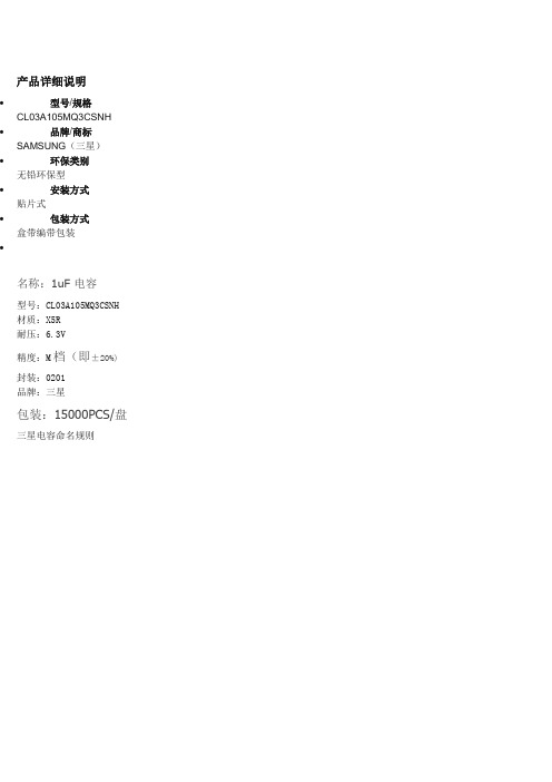
产品详细说明
∙型号/规格
CL03A105MQ3CSNH
∙品牌/商标SAMSUNG(三星)
∙环保类别
无铅环保型
∙安装方式
贴片式
∙包装方式
盒带编带包装
∙
名称:1uF 电容
型号:CL03A105MQ3CSNH 材质:X5R
耐压:6.3V
精度:M档(即±20%)封装:0201
品牌:三星
包装:15000PCS/盘三星电容命名规则
三星电容尺寸图
深圳市港丰源电子有限公司,是三星电子元器件一级代理商专业从事代理与经销SMD电子元器件,主营贴片电容,贴片电阻,钽电容,是以提供技术支持和售后维护为一体的电子元器件服务型公司。
在贴片电容行业积累了丰富的经验与技术,目前拥有各级员工几百余名,拥有一批高素质的管理团队和服务队伍。
代理的産品贴片电容渗透到各個电子行业:移动通信系统及终端(手机),数码电子产品(MP3,P-DVD,GPS,蓝牙)等工业品,家电,监控安防,医疗及军用设备。
公司拥有2000平方米的物流仓储基地,月庫存约10亿支的各品牌元器件,通过现化的物流操作模式从深圳仓储物流中心转送到全国各地客戶手中。
诚信待客:专业、诚信、优秀的产品代理商。
首选的品代理商,您滿意的代理商港丰源电子。
完善服务:为方便客戶的咨询与采购,我们提供了一站式电子元器件订购平台
欢迎新老客戶咨询洽谈!。
三星电容全系列规格书
March 2009MULTILAYERCERAMIC CAPACITORSAll information indicated in this catalog is as of March. 2009The specifications and designs contained herein may be subject to change without notice.Passive components Sales OfficeHead Office206, Cheomdansaneop Road,Youngtong-gu,Suwon, Kyonggi Province 443-743, KoreaEuropeTel:+82-31-210-6328E-mail:james.pyun@ AmericaTel:+82-31-210-6794E-mail:randy.kim@ AsiaTel:+82-31-210-5348E-mail:koogi@ DomesticTel:+82-31-210-3757E-mail:southjoy@Manufacturing SiteSuwon Plant (Korea)206 Cheomdansaneop Road, Youngtong -gu,Suwon, Kyonggi Province 443-743, KoreaTel:+82-31-210-6794E-mail:randy.kim@ Busan Plant (Korea)1623-2, Songjeong -dong,Kangseo -gu, Busan 618-270, Korea Tel:+82-51-970-7671E-mail:kyc.kweon@ Tianjin Plant (China)27, Heiniucheng -Road, Hexi District,Tianjin, China 300210Tel:+86-22-2830-3333(3450)E-mail:gk.ryu@ Philippines Plant (Philippines)Calamba Premiere International Park, Batino, Calamba, Laguna, Manila Tel:+63-2-809-2873E-mail:ksj1445@Asia sales officeShanghai OfficeRm 1408 Shanghai international trade center No 2200 Yan an (W )RD Shanghai China 200335Te l:86-21-6270-4168(274)E-mail:dennis.cha@ Shenzhen OfficeRm 4501, 45/F, New World Center,Yitian Road, Futian District,Shenzhen, China 518026Te l:86-755-8608-5581E-mail:jackson.xian@ Qingdao OfficeRm 1201. Growne Plaza Qingdao;76XiangGangZhong Rd, Qingdao;266071P.R. ChinaTe l:86-532-5779102E-mail:zhengguo.cui@ HongKong OfficeSuite 4511, Two int’l Finance Centre,8 Finance Street, Central, Hongkong Te l:852-2862-6350E-mail:vinsent.chou@ Singapore Office3 Church Street Samsung Hub #23-02 Singapore 049483Te l:(65)6833-3228E-mail:winson.yeong@ Thai OfficeWellgrow Industrial Estate,93 Moo 5 T. Bangsamak, A.Bangpakong Chachoengsao 24180 Thailand Te l:66-38-562-026E-mail:sbimm@ Taiwan Office399 9F -1, Ruey Kuang Rd., Neihu, Taipei, TaiwanTe l:886-2-2656-8356E-mail:kevin0130.wang@America sales officeIrvine Office3345 Michelson Drive,Suite 350,Irvine, CA 92612Tel:1-949-797-8047E-mail:sh386.kim@Europe sales officeFrankfurt Office Samsung hausAm Kronberger Hang 6D-65824 Schwalbach/Ts.Tel:49-6196-66-7255FAX:49-(0)6196-66-7755E-mail:frank.goebel@ Hungary OfficeH2310, Szigetszentmiklos, Leshegy u.2-4, HungaryTel:36-24-551-148E-mail:jun21c.lee@Domestic DistributorsKORCHIP INC#219-8 Gasan -dong, Gumchun -gu,Seoul, KoreaTel:+82-2-838-5588E-mail:hjh0064@ CHUNG HAN#16-96 Hangang -lo 3, Youngsan -Gu,Seoul, KoreaTel:+82-2-718-3322E-mail:bu1230choi@ SAMTDaekyung Bldg.,Daechi-Dong,Gangnam -Gu, Seoul, Korea Tel:+82-2-3458-9000E-mail:info@ CHUNGMAC#53-5 Wonhyolo3 Youngsan -gu, Seoul, KoreaTel:+82-2-716-6428~9E-mail:webmaster@anycam.co.kr APEXINTRoom #905. C -dong Woorimlion ,s,Valley 371-28, Gasan-dong,Guemcheon-Gu, Seoul, Korea Tel:+82-2-2026-2610(2)E-mail:info@apexint.co.krWe, Samsung, declare that our component MLCC is produced in accordance with EU RoHS directive.1.RoHS Compliance and restriction of BrThe following restricted materials are not used in packaging materials as well as products in compliance with the law and restriction.- Cd, Pb, Hg, Cr+6, As, Br and the compounds, PCB, asbestos- Bromic materials : PBBs, PBBOs, PBDO, PBDE, PBB2.No use of materials breaking Ozone layerThe following ODS materials are not used in our fabrication process.- ODS material : Freon, Haron, 1-1-1 TCE, CCl4, HCFCIf you want more detailed Information,Please Visit Samsung Electro-mechanics Website CONTENTSPart NumberingSystem4628353950525558627983GeneralCapacitorsUltra HighCapacitorsSuper SmallCapacitorsHigh VoltageCapacitorsCamera StrobeCircuit CapacitorsArray TypeCapacitorsLow ESLCapacitorsApplication Manualfor Surface MountingPackagingSpecificationPremium Capacitorsfor AutomotiveApplicationsReliability TestConditionPart Numbering SystemFeature Capacitance Table (General Capacitors)GeneralCapacitorsCapacitance Table (General Capacitors)Capacitance Table (General Capacitors)GeneralCapacitorsCapacitance Table (General Capacitors)Capacitance Table (General Capacitors)GeneralCapacitorsCapacitance Table (General Capacitors)Capacitance Table (General Capacitors)GeneralCapacitorsProduct Line Up (General Capacitors)Product Line Up (General Capacitors)GeneralCapacitorsCL10 R82CB8ANNCL10 010CB8ANNCL10 1R2CB8ANNCL10 1R5CB8ANNCL10 1R8CB8ANNCL10 020CB8ANNCL10 2R2CB8ANNCL10 2R7CB8ANNCL10 030CB8ANNCL10 3R3CB8ANNCL10 3R9CB8ANNCL10 040CB8ANNCL10 4R7CB8ANNCL10 050DB8ANNCL10 5R6DB8ANNCL10 060DB8ANNCL10 6R8DB8ANNCL10 070DB8ANNCL10 080DB8ANNCL10 8R2DB8ANNCL10 090DB8ANNCL10 100JB8NNNCL10 100J B8ANNCL10 120JB8NNNCL10 120JB8ANNCL10 150JB8NNNCL10 150JB8ANNCL10 180JB8NNNCL10 180J B8ANNCL10 220JB8NNNCL10 220JB8ANNCL10 270JB8NNNCL10 270JB8ANNCL10 330JB8NNNCL10 330JB8ANN0.821.001.201.501.802.002.202.703.003.303.904.004.705.005.606.006.807.008.008.209.0010101212151518182222272733330.25pF0.25pF0.25pF0.25pF0.25pF0.25pF0.25pF0.25pF0.25pF0.25pF0.25pF0.25pF0.25pF0.5pF0.5pF0.5pF0.5pF0.5pF0.5pF0.5pF0.5pF5%5%5%5%5%5%5%5%5%5%5%5%5%5%50505050505050505050505050505050505050505050505050505050505050505050500.900.900.900.900.900.900.900.900.900.900.900.900.900.900.900.900.900.900.900.900.900.900.900.900.900.900.900.900.900.900.900.900.900.900.90Part NumberThicknessMax. (mm)RatedVoltage(Vdc)CapacitanceToleranceCapacitance(pF)C P R S T U LSize L W (1.6 0.8mm)C0G P2H R2H S2H T2H U2J S2LCL10 390JB8NNNCL10 390JB8ANNCL10 470JB8NNNCL10 470JB8ANNCL10 560JB8NNNCL10 560JB8ANNCL10 680JB8NNNCL10 680JB8ANNCL10 820JB8NNNCL10 820JB8ANNCL10 101JB8NNNCL10 101JB8ANNCL10 121JB8NNNCL10 121JB8ANNCL10 151JB8NNNCL10 151JB8ANNCL10 181JB8NNNCL10 181JB8ANNCL10 221JB8NNNCL10 221JB8ANNCL10 271JB8NNNCL10 271JB8ANNCL10 331JB8NNNCL10 331JB8ANNCL10 391JB8NNNCL10 471JB8NNNCL10 471JB8ANNCL10 561JB8NNNCL10 681JB8NNNCL10 681JB8ANNCL10 821JB8NNNCL10 102JB8NNNCL10 122JB8NNNCL10 222JB8NNNCL10 332JA8NNN3939474756566868828210010012012015015018018022022027027033033039047047056068068082010001200220033005%5%5%5%5%5%5%5%5%5%5%5%5%5%5%5%5%5%5%5%5%5%5%5%5%5%5%5%5%5%5%5%5%5%5%50505050505050505050505050505050505050505050505050505050505050505050250.900.900.900.900.900.900.900.900.900.900.900.900.900.900.900.900.900.900.900.900.900.900.900.900.900.900.900.900.900.900.900.900.900.900.90Part NumberThicknessMax. (mm)RatedVoltage(Vdc)CapacitanceToleranceCapacitance(pF)C P R S T U LSize L W (1.6 0.8mm)C0G P2H R2H S2H T2H U2J S2LProduct Line Up (General Capacitors)Product Line Up (General Capacitors)GeneralCapacitorsCL21 560JBANNNCL21 680JBANNNCL21 820JBANNNCL21 101JBANNNCL21 101JBAANNCL21 121JBANNNCL21 151JBANNNCL21 181JBANNNCL21 221JBANNNCL21 271JBANNNCL21 331JBANNNCL21 331JBAANNCL21 391JBANNNCL21 471JBANNNCL21 471JBAANNCL21 561JBANNNCL21 821JBCNNNCL21 821JBAANNCL21 102JBCNNNCL21 122JBFNNNCL21 152JBFNNNCL21 182JBFNNNCL21 222JBFNNNCL21 332JAFNNNCL21 332JBFNNNCL21 392JBFNNNCL21 472JAFNNNCL21 472JBFNNNCL21 562JBFNNNCL21 103JBFNNN56688210010012015018022027033033039047047056082082010001200150018002200330033003900470047005600100005%5%5%5%5%5%5%5%5%5%5%5%5%5%5%5%5%5%5%5%5%5%5%5%5%5%5%5%5%5%5050505050505050505050505050505050505050505050255050255050500.750.750.750.750.750.750.750.750.750.750.750.750.750.750.750.750.950.750.951.351.351.351.351.351.351.351.351.351.351.35Part NumberThicknessMax. (mm)RatedVoltage(Vdc)CapacitanceToleranceCapacitance(pF)C P R S T U LSize L W (2.0 1.25mm)C0G P2H R2H S2H T2H U2J S2LCL21 R47CBAANNCL21 0R5CBAANNCL21 R68CBAANNCL21 R82CBAANNCL21 010CBAANNCL21 1R2CBAANNCL21 1R5CBAANNCL21 1R8CBAANNCL21 020CBAANNCL21 2R2CBAANNCL21 2R7CBAANNCL21 030CBAANNCL21 3R3CBAANNCL21 3R9CBAANNCL21 040CBAANNCL21 4R7CBAANNCL21 050DBAANNCL21 5R6DBAANNCL21 060DBAANNCL21 6R8DBAANNCL21 070DBAANNCL21 080DBAANNCL21 8R2DBAANNCL21 090DBAANNCL21 100JBANNNCL21 100J BAANNCL21 120JBANNNCL21 120J BAANNCL21 150JBANNNCL21 180J BANNNCL21 220JBANNNCL21 270JBANNNCL21 330JBANNNCL21 390JBANNNCL21 470JBANNN0.470.500.680.821.001.201.501.802.002.202.703.003.303.904.004.705.005.606.006.807.008.008.209.0010101212151822273339470.25pF0.25pF0.25pF0.25pF0.25pF0.25pF0.25pF0.25pF0.25pF0.25pF0.25pF0.25pF0.25pF0.25pF0.25pF0.25pF0.5pF0.5pF0.5pF0.5pF0.5pF0.5pF0.5pF0.5pF5%5%5%5%5%5%5%5%5%5%5%50505050505050505050505050505050505050505050505050505050505050505050500.750.750.750.750.750.750.750.750.750.750.750.750.750.750.750.750.750.750.750.750.750.750.750.750.750.750.750.750.750.750.750.750.750.750.75Part NumberThicknessMax. (mm)RatedVoltage(Vdc)CapacitanceToleranceCapacitance(pF)C P R S T U LSize L W (2.0 1.25mm)C0G P2H R2H S2H T2H U2J S2LProduct Line Up (General Capacitors)Product Line Up (General Capacitors)GeneralCapacitorsProduct Line Up (General Capacitors)Product Line Up (General Capacitors)GeneralCapacitorsProduct Line Up (General Capacitors)Product Line Up (General Capacitors)GeneralCapacitorsProduct Line Up (General Capacitors)Product Line Up (General Capacitors)GeneralCapacitorsProduct Line Up (General Capacitors)Product Line Up (General Capacitors)GeneralCapacitorsUltra HighCapacitorsCapacitance Table (Ultra High Capacitors)Capacitance Table (Ultra High Capacitors)Ultra HighCapacitorsCL10F225ZP8NNNCL21F106ZPFNNNCL31F226ZPHNNNCL32F226ZPJNNNCL05F105ZQ5NNNCL10F475ZQ8NNNCL32F107ZQJNNNY5V(EIA)Y5V(EIA)Y5V(EIA)Y5V(EIA)Y5V(EIA)Y5V(EIA)Y5V(EIA)2.21022221.04.710080%/-20%80%/-20%80%/-20%80%/-20%80%/-20%80%/-20%80%/-20%101010106.36.36.30.901.351.802.700.550.902.70-82~+22%(-30~+85 )-82~+22%(-30~+85 )-82~+22%(-30~+85 )-82~+22%(-30~+85 )-82~+22%(-30~+85 )-82~+22%(-30~+85 )-82~+22%(-30~+85 )1.60 0.802.00 1.253.20 1.603.20 2.501.00 0.501.60 0.803.20 2.50Part NumberThicknessMax. (mm)RatedVoltage(Vdc)CapacitanceToleranceCapacitanceTCCodeTemperatureCharacteristicsSize L W(mm)mark means packaging code. If you want to learn the code or quantity in detail, please see p 81.Small chip size03 Series(C0G) MLCC shows very low ESR valae.02 and 03 Series are suited to only reflow soldering02 and 03 Series are suited to miniature RF module,portable equipment and high frequency circuitVCO, Tuner, RF ModuleMCM ModuleMobile phone, Wireless LAN, Note PCFor using special purpose like Military, Medical, Aviation, Automobile device should be following a special specification.FeatureApplicationStructure and DimensionsCodeEIACode L W T BWDimension(mm)0.3 0.030.3 0.030.6 0.0302010.15 0.05030.2 0.020.2 0.020.4 0.02010050.07~0.1402CL21X106KAYNNNCL31X106KAHNNNCL21X106KOYNNNCL21X106KPCLNNCL05X105KQ5NNNCL10X105KQ8NNNCL21X225KQFNNNCL21X475KQFNNNCL10X106KQ8NNNCL21X106KQQNNNCL31X106KQHNNNCL21X226KQQNNNCL21X106KRCLNNCL31B475KAHNNNCL31B106KAHNNNCL31B475KOHNNNCL31B106KOHNNNCL21B225KQFNNNCL21B225KPFNNNCL21B106KQQNNNCL31B106KQHNNNCL32B226KQJNNNX6S(EIA)X6S(EIA)X6S(EIA)X6S(EIA)X6S(EIA)X6S(EIA)X6S(EIA)X6S(EIA)X5R(EIA)X6S(EIA)X6S(EIA)X6S(EIA)X6S(EIA)X7R(EIA)X7R(EIA)X7R(EIA)X7R(EIA)X7R(EIA)X7R(EIA)X7R(EIA)X7R(EIA)X7R(EIA)101010101.01.02.24.710101022104.7104.7102.22.210102210%10%10%10%10%10%10%10%10%10%10%10%10%10%10%10%10%10%10%10%10%10%252516106.36.36.36.36.36.36.36.342525161610106.36.36.31.451.801.450.950.550.901.351.350.901.401.801.400.951.801.801.801.801.351.351.351.802.7022%(-55~+105 )22%(-55~+105 )22%(-55~+105 )22%(-55~+105 )22%(-55~+105 )22%(-55~+105 )22%(-55~+105 )22%(-55~+105 )15%(-55~+85 )22%(-55~+105 )22%(-55~+105 )22%(-55~+105 )22%(-55~+105 )15%(-55~+125 )15%(-55~+125 )15%(-55~+125 )15%(-55~+125 )15%(-55~+125 )15%(-55~+125 )15%(-55~+125 )15%(-55~+125 )15%(-55~+125 )2.00 1.253.20 1.602.00 1.252.00 1.251.00 0.501.60 0.802.00 1.252.00 1.251.60 0.802.00 1.253.20 1.602.00 1.252.00 1.253.20 1.603.20 1.603.20 1.603.20 1.602.00 1.252.00 1.252.00 1.253.20 1.603.20 2.50Part NumberThicknessMax. (mm)RatedVoltage(Vdc)CapacitanceToleranceCapacitanceTCCodeTemperatureCharacteristicsSize L W(mm)Product Line Up (Ultra High Capacitors)Super SmallCapacitorsSuper Small CapacitorsProduct Line Up (Super Small Size Capacitors)FeatureHigh VoltageCapacitorsHigh Voltage CapacitorsCapacitance Table (High Voltage Capacitors)Capacitance Table (High Voltage Capacitors)High VoltageCapacitorsCapacitance Table (High Voltage Capacitors)Product Line Up (High Voltage Capacitors)High VoltageCapacitorsProduct Line Up (High Voltage Capacitors)Product Line Up (High Voltage Capacitors)High VoltageCapacitorsCL31B222KGFNNNCL31B332KGFNNNCL31B472KGFNNNCL31B682KGFNNNCL31B103KGFNNNCL32B153KGFNNNCL32B223KGFNNNCL43B473KGFNNNCL43B104KG INNNCL21B153KEFNNNCL31B473KEHNNNCL32B104KE J NNNCL43B474KE JNNNCL21B221KDCNNNCL21B331KDCNNNCL31B471KDCNNNCL21B102KDCNNNCL21B222KDCNNNCL31B222KDCNNNCL21B472KDCNNNCL31B472KDCNNNCL21B103KDCNNNCL31B153KDCNNNCL31B223KDCNNNCL31B333KDFNNNCL31B473KDFNNNCL32B473KDHNNNCL31B104KDHNNNCL43B104KDFNNNCL21B221KCANNNCL21B471KCANNNCL10B102KC8NNNCL21B102KCANNNCL21B222KCANNNCL21B332KCANNNX7R(EIA)X7R(EIA)X7R(EIA)X7R(EIA)X7R(EIA)X7R(EIA)X7R(EIA)X7R(EIA)X7R(EIA)X7R(EIA)X7R(EIA)X7R(EIA)X7R(EIA)X7R(EIA)X7R(EIA)X7R(EIA)X7R(EIA)X7R(EIA)X7R(EIA)X7R(EIA)X7R(EIA)X7R(EIA)X7R(EIA)X7R(EIA)X7R(EIA)X7R(EIA)X7R(EIA)X7R(EIA)X7R(EIA)X7R(EIA)X7R(EIA)X7R(EIA)X7R(EIA)X7R(EIA)X7R(EIA)2.23.34.76.81015224710015471004700.220.330.471.02.22.24.74.71015223347471001000.220.471.01.02.23.310%10%10%10%10%10%10%10%10%10%10%10%10%10%10%10%10%10%10%10%10%10%10%10%10%10%10%10%10%10%10%10%10%10%10%5005005005005005005005005002502502502502002002002002002002002002002002002002002002002001001001001001001001.351.351.351.351.351.351.351.352.201.351.802.802.801.001.001.001.001.001.001.001.001.001.001.001.351.351.801.801.350.750.750.900.750.750.7515%(-55~+125 )15%(-55~+125 )15%(-55~+125 )15%(-55~+125 )15%(-55~+125 )15%(-55~+125 )15%(-55~+125 )15%(-55~+125 )15%(-55~+125 )15%(-55~+125 )15%(-55~+125 )15%(-55~+125 )15%(-55~+125 )15%(-55~+125 )15%(-55~+125 )15%(-55~+125 )15%(-55~+125 )15%(-55~+125 )15%(-55~+125 )15%(-55~+125 )15%(-55~+125 )15%(-55~+125 )15%(-55~+125 )15%(-55~+125 )15%(-55~+125 )15%(-55~+125 )15%(-55~+125 )15%(-55~+125 )15%(-55~+125 )15%(-55~+125 )15%(-55~+125 )15%(-55~+125 )15%(-55~+125 )15%(-55~+125 )15%(-55~+125 )3.20 1.603.20 1.603.20 1.603.20 1.603.20 1.603.20 2.503.20 2.504.50 3.204.50 3.202.00 1.253.20 1.603.20 2.504.50 3.202.00 1.252.00 1.253.20 1.602.00 1.252.00 1.253.20 1.602.00 1.253.20 1.602.00 1.253.20 1.603.20 1.603.20 1.603.20 1.603.20 2.503.20 1.604.50 3.202.00 1.252.00 1.251.60 0.802.00 1.252.00 1.252.00 1.25Part NumberThicknessMax. (mm)RatedVoltage(Vdc)CapacitanceToleranceCapacitanceTCCodeTemperatureCharacteristicsSize L W(mm)Product Line Up (High Voltage Capacitors)Product Line Up (High Voltage Capacitors)CL10B472KC8NNNCL21B472KCANNNCL21B682KCANNNCL10B103KC8NNNCL21B103KCANNNCL32B103KCFNNNCL21B153KCCNNNCL31B153KCCNNNCL21B223KCFNNNCL31B223KCCNNNCL31B333KCCNNNCL21B473KCFNNNCL31B473KCCNNNCL31B104KCFNNNCL31B154KCHNNNCL32B154KCFNNNCL32B224KCHNNNCL43B224KCFNNNCL32B334KCHNNNCL43B334KCFNNNCL32B474KCI NNNCL43B474KCHNNNCL31B105KCHNNNCL32B105KCJNNNCL43B105KCJNNNCL55B105KCHNNNX7R(EIA)X7R(EIA)X7R(EIA)X7R(EIA)X7R(EIA)X7R(EIA)X7R(EIA)X7R(EIA)X7R(EIA)X7R(EIA)X7R(EIA)X7R(EIA)X7R(EIA)X7R(EIA)X7R(EIA)X7R(EIA)X7R(EIA)X7R(EIA)X7R(EIA)X7R(EIA)X7R(EIA)X7R(EIA)X7R(EIA)X7R(EIA)X7R(EIA)X7R(EIA)4.74.76.8101010151522223347471001501502202203303304704701.01.01.01.010%10%10%10%10%10%10%10%10%10%10%10%10%10%10%10%10%10%10%10%10%10%10%10%10%10%1001001001001001001001001001001001001001001001001001001001001001001001001001000.900.750.750.900.751.351.001.001.351.001.001.351.001.351.801.351.801.351.801.352.201.801.802.802.801.8015%(-55~+125 )15%(-55~+125 )15%(-55~+125 )15%(-55~+125 )15%(-55~+125 )15%(-55~+125 )15%(-55~+125 )15%(-55~+125 )15%(-55~+125 )15%(-55~+125 )15%(-55~+125 )15%(-55~+125 )15%(-55~+125 )15%(-55~+125 )15%(-55~+125 )15%(-55~+125 )15%(-55~+125 )15%(-55~+125 )15%(-55~+125 )15%(-55~+125 )15%(-55~+125 )15%(-55~+125 )15%(-55~+125 )15%(-55~+125 )15%(-55~+125 )15%(-55~+125 )1.60 0.802.00 1.252.00 1.251.60 0.802.00 1.253.20 2.502.00 1.253.20 1.602.00 1.503.20 1.603.20 1.602.00 1.253.20 1.603.20 1.603.20 1.603.20 2.503.20 2.504.50 3.203.20 2.504.50 3.203.20 2.504.50 3.203.20 1.603.20 2.504.50 3.205.70 5.00Part NumberThicknessMax. (mm)RatedVoltage(Vdc)CapacitanceToleranceCapacitanceTCCodeTemperatureCharacteristicsSize L W(mm)mark means packaging code. If you want to learn the code or quantity in detail, please see p 81.High VoltageCapacitorsCodeEIACodeL W T BWDimension(mm)0.85(0.15)1.10(0.15)1.60(0.20)0.500.3/-0.33.200.20 1.600.20120631Suitable for the trigger of the flash circuitHighly reliable performanceSuperior in bias characteristicsSoft termination with a Ni/Sn plated overcoatStrobe Circuit FeatureApplicationStructure and DimensionCapacitance Table (Camera Strobe Circuit Capacitors)Camera StrobeCircuit CapacitorsFeature Capacitance TableArray TypeCapacito rsProduct Line Up (Array Type Capacitors)FeatureLow ESLCapacitorsCapacitance Table (Low ESL Capacitors)Product Line Up (Low ESL Capacitors)Low ESL CapacitorsReliability TestConditionReliability Test ConditionPremium Capacitors for Automotive ApplicationsPart Numbering System (Automotive Capacitors)Premium Capacitorsfor AutomotiveApplicationsFeatureCapacitance Table (Automotive Capacitors)Premium Capacitorsfor AutomotiveApplicationsProduct Line Up (Automotive Capacitors)Product Line Up (Automotive Capacitors)Premium Capacitorsfor AutomotiveApplicationsProduct Line Up (Automotive Capacitors)CL21C221JC6*PN CL21C331JC6*PN CL21C471JCC *PN CL21C681JCC *PN CL21C102JCC *PN CL21C102JCF *PN CL21C122JBC *PN CL21C152JBC *PN CL21C182JBC *PN CL21C222JBC *PN CL21C272JBC *PN CL21C332JBC *PN CL21C392JBC *PN CL21C472JBC *PN CL21C562JBC *PN CL21C122JBF *PN CL21C152JBF *PN CL21C182JBF *PN CL21C222JBF *PN CL21C272JBF *PN CL21C332JBF *PN CL21C392JBF *PN CL21C472JBF *PN CL21C562JBF *PN CL21C682JBF *PN CL21C822JBF *PN CL21C103JBF *PNC0G(EIA)C0G(EIA)C0G(EIA)C0G(EIA)C0G(EIA)C0G(EIA)C0G(EIA)C0G(EIA)C0G(EIA)C0G(EIA)C0G(EIA)C0G(EIA)C0G(EIA)C0G(EIA)C0G(EIA)C0G(EIA)C0G(EIA)C0G(EIA)C0G(EIA)C0G(EIA)C0G(EIA)C0G(EIA)C0G(EIA)C0G(EIA)C0G(EIA)C0G(EIA)C0G(EIA))220 330 470680 1.0 1.0 1.21.5 1.82.2 2.73.3 3.94.75.6 1.2 1.5 1.8 2.2 2.7 3.3 3.9 4.7 5.66.8 8.2 10.05% 5% 5% 5% 5% 5% 5% 5% 5% 5% 5% 5% 5% 5% 5% 5% 5% 5% 5% 5% 5% 5% 5% 5% 5% 5% 5%1001001001001001005050505050505050505050505050505050505050500.700.700.950.950.951.350.950.950.950.950.950.950.950.950.951.351.351.351.351.351.351.351.351.351.351.351.3530ppm/ (-55~+125 ) 30ppm/ (-55~+125 ) 30ppm/ (-55~+125 ) 30ppm/ (-55~+125 ) 30ppm/ (-55~+125 ) 30ppm/ (-55~+125 ) 30ppm/ (-55~+125 ) 30ppm/ (-55~+125 ) 30ppm/ (-55~+125 ) 30ppm/ (-55~+125 ) 30ppm/ (-55~+125 ) 30ppm/ (-55~+125 ) 30ppm/ (-55~+125 ) 30ppm/ (-55~+125 ) 30ppm/ (-55~+125 ) 30ppm/ (-55~+125 ) 30ppm/ (-55~+125 ) 30ppm/ (-55~+125 ) 30ppm/ (-55~+125 ) 30ppm/ (-55~+125 ) 30ppm/ (-55~+125 ) 30ppm/ (-55~+125 ) 30ppm/ (-55~+125 ) 30ppm/ (-55~+125 ) 30ppm/ (-55~+125 ) 30ppm/ (-55~+125 )30ppm/ (-55~+125 )2.00 1.252.00 1.252.00 1.252.00 1.252.00 1.252.00 1.252.00 1.252.00 1.252.00 1.252.00 1.252.00 1.252.00 1.252.00 1.252.00 1.252.00 1.252.00 1.252.00 1.252.00 1.252.00 1.252.00 1.252.00 1.252.00 1.252.00 1.252.00 1.252.00 1.252.00 1.252.00 1.25Part Number Thickness Max. (mm)RatedVoltage (Vdc)Capacitance Tolerance CapacitanceTC CodeTemperature CharacteristicsSize L W(mm)Premium Capacitors for Automotive Applications Capacitance Table (Automotive Capacitors)*mark means design code. If you want more information , Please check with our sales representatives or product engineers. mark means packaging code. If you want to learn the code or quantity in detail, please see p 81.CL10B473KO8*PN CL10B683KO8*PN CL10B104KO8*PN CL10B103KA8*PN CL10B153KA8*PN CL10B223KA8*PN CL10B333KA8*PN CL10B473KA8*PN CL10B683KA8*PN CL10B104KA8*PN CL10B102KB8*PN CL10B152KB8*PN CL10B222KB8*PN CL10B332KB8*PN CL10B472KB8*PN CL10B682KB8*PN CL10B103KB8*PN CL10B153KB8*PN CL10B223KB8*PN CL10B333KB8*PN CL10B473KB8*PN CL10B683KB8*PN CL10B104KB8*PN CL10B102KC8*PN CL10B152KC8*PN CL10B222KC8*PN CL10B332KC8*PN CL10B472KC8*PN CL10B682KC8*PN CL10B103KC8*PN CL10B221KC8*PN CL10B331KC8*PN CL10B471KC8*PNCapacitance Product Line Up (Automotive Capacitors)Part Number ThicknessMax. (mm)0.900.900.900.900.900.900.900.900.900.900.900.900.900.900.900.900.900.900.900.900.900.900.900.900.900.900.900.900.900.900.900.900.90Capacitance Tolerance Size L W (mm)RatedVoltage(Vdc)Temperature CharacteristicsTC Code10% 10% 10% 10% 10% 10% 10% 10% 10% 10% 10% 10% 10% 10% 10% 10% 10% 10% 10% 10% 10% 10% 10% 10% 10% 10% 10% 10% 10% 10% 10% 10% 10%47 68 100 10 15 22 33 47 68 100 1.0 1.5 2.2 3.3 4.7 6.8 10 15 22 33 47 68 100 1.0 1.5 2.2 3.3 4.7 6.8 10 220 330 4701.60 0.801.60 0.801.60 0.801.60 0.801.60 0.801.60 0.801.60 0.801.60 0.801.60 0.801.60 0.801.60 0.801.60 0.801.60 0.801.60 0.801.60 0.801.60 0.801.60 0.801.60 0.801.60 0.801.60 0.801.60 0.801.60 0.801.60 0.801.60 0.801.60 0.801.60 0.801.60 0.801.60 0.801.60 0.801.60 0.801.60 0.801.60 0.801.60 0.80X7R(EIA)X7R(EIA)X7R(EIA)X7R(EIA)X7R(EIA)X7R(EIA)X7R(EIA)X7R(EIA)X7R(EIA)X7R(EIA)X7R(EIA)X7R(EIA)X7R(EIA)X7R(EIA)X7R(EIA)X7R(EIA)X7R(EIA)X7R(EIA)X7R(EIA)X7R(EIA)X7R(EIA)X7R(EIA)X7R(EIA)X7R(EIA)X7R(EIA)X7R(EIA)X7R(EIA)X7R(EIA)X7R(EIA)X7R(EIA)X7R(EIA)X7R(EIA)X7R(EIA)15%(-55~+125 ) 15%(-55~+125 ) 15%(-55~+125 ) 15%(-55~+125 ) 15%(-55~+125 ) 15%(-55~+125 ) 15%(-55~+125 ) 15%(-55~+125 ) 15%(-55~+125 ) 15%(-55~+125 ) 15%(-55~+125 ) 15%(-55~+125 ) 15%(-55~+125 ) 15%(-55~+125 ) 15%(-55~+125 ) 15%(-55~+125 ) 15%(-55~+125 ) 15%(-55~+125 ) 15%(-55~+125 ) 15%(-55~+125 ) 15%(-55~+125 ) 15%(-55~+125 ) 15%(-55~+125 ) 15%(-55~+125 ) 15%(-55~+125 ) 15%(-55~+125 ) 15%(-55~+125 ) 15%(-55~+125 ) 15%(-55~+125 ) 15%(-55~+125 ) 15%(-55~+125 ) 15%(-55~+125 ) 15%(-55~+125 )1616162525252525252550505050505050505050505050100100100100100100100100100100Premium Capacitors for Automotive Applications CL10B681KC8*PN CL21B104KOC *PN CL21B154KOF *PN CL21B224KOF *PN CL21B334KOF *PN CL21B474KOF *PN CL21B473KAC *PN CL21B683KAC *PN CL21B104KAC *PN CL21B154KAF *PN CL21B224KAF *PN CL21B334KAF *PN CL21B474KAF *PN CL21B102KB6*PN CL21B152KB6*PN CL21B222KB6*PN CL21B332KB6*PN CL21B472KB6*PN CL21B682KB6*PN CL21B103KB6*PN CL21B153KB6*PN CL21B223KB6*PN CL21B333KBC *PN CL21B473KBC *PN CL21B683KBC *PN CL21B104KBC *PN CL21B104KBF *PN CL21B154KBF *PN CL21B224KBF *PN CL21B334KBF *PN CL21B474KBF *PN CL21B102KC6*PN CL21B152KC6*PNCapacitance Product Line Up (Automotive Capacitors)Part Number ThicknessMax. (mm)0.900.951.351.351.351.350.950.950.951.351.351.351.350.700.700.700.700.700.700.700.700.700.950.950.950.951.351.351.351.351.350.700.70Capacitance Tolerance Size L W (mm)RatedVoltage(Vdc)Temperature CharacteristicsTC Code10% 10% 10% 10% 10% 10% 10% 10% 10% 10% 10% 10% 10% 10% 10% 10% 10% 10% 10% 10% 10% 10% 10% 10% 10% 10% 10% 10% 10% 10% 10% 10% 10%680 100 150 220 330 470 47 68 100 150 220 330 470 1.0 1.5 2.2 3.3 4.7 6.8 10 15 22 33 47 68 100 100 150 220 330 470 1.0 1.51.60 0.802.00 1.252.00 1.252.00 1.252.00 1.252.00 1.252.00 1.252.00 1.252.00 1.252.00 1.252.00 1.252.00 1.252.00 1.252.00 1.252.00 1.252.00 1.252.00 1.252.00 1.252.00 1.252.00 1.252.00 1.252.00 1.252.00 1.252.00 1.252.00 1.252.00 1.252.00 1.252.00 1.252.00 1.252.00 1.252.00 1.252.00 1.252.00 1.25X7R(EIA)X7R(EIA)X7R(EIA)X7R(EIA)X7R(EIA)X7R(EIA)X7R(EIA)X7R(EIA)X7R(EIA)X7R(EIA)X7R(EIA)X7R(EIA)X7R(EIA)X7R(EIA)X7R(EIA)X7R(EIA)X7R(EIA)X7R(EIA)X7R(EIA)X7R(EIA)X7R(EIA)X7R(EIA)X7R(EIA)X7R(EIA)X7R(EIA)X7R(EIA)X7R(EIA)X7R(EIA)X7R(EIA)X7R(EIA)X7R(EIA)X7R(EIA)X7R(EIA)15%(-55~+125 ) 15%(-55~+125 ) 15%(-55~+125 ) 15%(-55~+125 ) 15%(-55~+125 ) 15%(-55~+125 ) 15%(-55~+125 ) 15%(-55~+125 ) 15%(-55~+125 ) 15%(-55~+125 ) 15%(-55~+125 ) 15%(-55~+125 ) 15%(-55~+125 ) 15%(-55~+125 ) 15%(-55~+125 ) 15%(-55~+125 ) 15%(-55~+125 ) 15%(-55~+125 ) 15%(-55~+125 ) 15%(-55~+125 ) 15%(-55~+125 ) 15%(-55~+125 ) 15%(-55~+125 ) 15%(-55~+125 ) 15%(-55~+125 ) 15%(-55~+125 ) 15%(-55~+125 ) 15%(-55~+125 ) 15%(-55~+125 ) 15%(-55~+125 ) 15%(-55~+125 ) 15%(-55~+125 ) 15%(-55~+125 )100161616161625252525252525505050505050505050505050505050505050100100*mark means design code. If you want more information , Please check with our sales representatives or product engineers. mark means packaging code. If you want to learn the code or quantity in detail, please see p 81.*mark means design code. If you want more information , Please check with our sales representatives or product engineers. mark means packaging code. If you want to learn the code or quantity in detail, please see p 81.。
三星0603 22uf电容规格书
三星0603 22uf电容规格书三星0603 22uf电容规格书的解读与应用一、引言在现代电子产品中,电容作为一种重要的被动元件,在电路中扮演着储存电荷、滤波、耦合等重要作用。
而三星0603 22uf电容规格书作为电容的一种,其规格书所包含的信息对于电子工程师和电子爱好者来说是至关重要的。
在本篇文章中,我们将深度解读三星0603 22uf电容规格书的内容,并探讨其在电路设计和应用中的重要性。
二、三星0603 22uf电容规格书的解读1. 产品型号:三星0603 22uf电容规格书所指代的产品型号为0603,22uf。
其中,0603代表了电容的封装尺寸,而22uf则代表了电容的容量大小。
理解这一点对于正确选型和应用至关重要。
2. 规格参数:在规格书中,通常包含了电容的电压值、容差、温度特性等重要参数。
在选型过程中,需要根据具体的电路要求和环境条件来选择合适的规格参数,以确保电路稳定性和性能。
3. 使用注意事项:在规格书中,也会包含一些使用注意事项和贮存条件,这些信息对于保证电容性能和寿命至关重要。
在使用和贮存过程中需要严格按照规格书要求进行操作。
三、三星0603 22uf电容在电路设计和应用中的重要性作为一种常见的电容型号,三星0603 22uf电容在电路设计和应用中扮演着重要的角色。
由于其封装尺寸小巧,适合于电子产品的迷你化设计,因此在手机、平板等智能设备中得到了广泛应用。
22uf的较大容量可以满足一些对电荷储存和稳压要求较高的电路,例如稳压电路、滤波电路等。
在电子产品设计中,正确选用和应用三星0603 22uf电容对于提高电路性能和稳定性具有重要意义。
四、对三星0603 22uf电容的个人观点和理解在我看来,三星0603 22uf电容作为一种电子元件,其规格书所包含的信息对于电子工程师和电子爱好者来说是非常重要的。
通过深入了解其规格书的内容,可以更好地应用于实际电路设计中,并确保电路工作的稳定性和性能。
SAMSUNG三星贴装电容标称说明
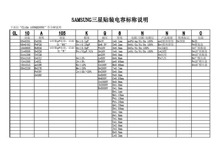
CL 10A105KQ8NNN C层 层 03=020引C=C精用B=±0封引pF 耐=4V 引=0封引高高A=P量层Ag层Ni层脚n下引00包A=2 N= B=05=0402P=P2留C=±0封25pF 纸=排封3V 2=0封2高高N=Ni层Cu层Ni层脚n下引00包B=4 P= 引0=0排03耐=耐2留D=±0封5pF P=引0V 3=0封3高高用=Cu层Ni层脚n下引00包C= 纸 C=7作 2引=0星05脚=脚2留F=±V引pF,V引包精=引排V 4=0封4高高称=Ni层Cu层Ni层脚n下引00包称=称盘CC 0=引3作 3引=引20排T=T2留A=25V 5=0封5高高N= D=引3作 32=引2引0U=U2J 用=±2包称=35V 排=0封排高高P=特=7作 42=引星0星称=脚2称J=±5包B=50V A=0封排5高高F=引3作 43=引星引2A=X5耐K=±引0包C=引00V B=0封排排高高脚=引0作55=2220B=X7耐M=±20包D=200V 7=0封7高高F=Y5V Z=±星0层-20包特=250V 星=0封星高高X=X排脚用=500V N=0封星高高留=排30V C=0封星5高高盘=引000V 9=0封9高高J=2000V D=引封0高高K=3000V精=引封0高高特=引封引高高M=引封引5高高P=引封引5高高F=引封25高高纸=引封25高高脚=引封35高高用=引封4高高留=引封排高高T=引封排高高U=引封星高高盘=2封0高高J=2封5高高K=3封0高高称=3封2高高脚AM脚UN用脚AM脚UN用C称引0A下引05K纸星NNNC引 pF耐02 pF耐。
- 1、下载文档前请自行甄别文档内容的完整性,平台不提供额外的编辑、内容补充、找答案等附加服务。
- 2、"仅部分预览"的文档,不可在线预览部分如存在完整性等问题,可反馈申请退款(可完整预览的文档不适用该条件!)。
- 3、如文档侵犯您的权益,请联系客服反馈,我们会尽快为您处理(人工客服工作时间:9:00-18:30)。
1.0
1.0
1.5
1.0 1.2 1.5 1.8
1.0 1.2 1.5 1.8
1.1 1.3 1.6 2.0
Capacitance Step
2.2
2.2
3.3
2.2 2.7 3.3 3.9
2.2 2.7 3.3 3.9
Symbol D G I J K
Rated Voltage(Vdc) 200V 500V 1000V 2000V 3000V
Multilayer Ceramic Capacitor
●7 THICKNESS OPTION
Symbol N A B C D E
Description of the Code Standard thickness (please refer to standard thickness table on next page) Thinner than standard thickness Thicker than standard thickness Standard Thickness High Q ( Low ` D.F ` ) Sn-100% (High-Q) Sn-100% (General)
● Application - High Frequency Circuit(Tuner, VCO, PAM etc) - General Power Supply Circuit(SMPS etc) - DC-DC Converter - General Electronic Circuit
Capacitance Change (ΔC : %)
± 15 ± 15
+22 ~ -82
Operation Temperature Range
-55 ~ +85℃ -55 ~ +125℃ -30 ~ +85℃
Multilayer Ceramic Capacitor
●4 NOMINAL CAPACITANCE
www.cdindustries.hk
Multilayer Ceramic Capacitor
■ PREVIOUS PART NUMBERING
CL 10 C 101 J B N C ●1 ●2 ●3 ●4 ●5 ●6 ●7 ●8
●1 SAMSUNG Multilayer Ceramic Capacitor ●2 Type(Size) ●3 Capacitance Temperature Characteristics ●4 Nominal Capacitance ●5 Capacitance Tolerance ●6 Rated Voltage ●7 Thickness Option ●8 Packaging Type
※ Please Consult us for other termination type.
●8 PACKAGING TYPE
Symbol B P C D E
Packaging Bulk
Cassette Paper Tape, 7" Reel Paper Tape, 13" Reel Embossed Tape, 7" Reel
example) 100 : 10 × 10o = 10pF 102 : 10 × 102 = 1000pF 020 : 2 × 10o = 2pF 1R5 : 1.5pF
●5 CAPACITANCE TOLERANCE
Temperature Characteristics
Symbol
Tolerance
above 10pF
C0G P2H R2H S2H T2H U2J
☞ K : ±250 PPM/℃ J : ±120 PPM/℃ H : ±60 PPM/℃ G : ±30 PPM/℃
▶ CLASS Ⅱ(High Dielectric Constant)
Symbol
A B F
EIA Code
X5R X7R Y5V
Applicable Capacitance & Range 0.5 ~ 3pF 0.5 ~ 10pF 6 ~ 10pF
E-24 Series for over 10pF
E-12 Series E-6 Series
●6 RATED VOLTAGE
Symbol Q P O A B C
Rated Voltage(Vdc) 6.3V 10V 16V 25V 50V 100V
0.5 ± 0.05
0.5 ± 0.05
0.8 ± 0.1
0.8 ± 0.1
1.25 ± 0.1
1.25± 0.1
1.6 ± 0.2
1.6 ± 0.2
2.5 ± 0.2
2.5 ± 0.2
3.2 ± 0.3
3.2 ± 0.3
5.0 ± 0.4
3.2 ± 0.3
BW 0.15±0.05 0.2+0.15/-0.1 0.3 ± 0.2 0.5+0.2/-0.3 0.5+0.2/-0.3 0.6 ± 0.3 0.8 ± 0.3 1.0 ± 0.3
■ FEATURE AND APPLICATION
● Feature - Miniature Size - Wide Capacitance and Voltage Range - Highly Reliable Performance - Tape & Reel for Surface Mount Assembly - Low ESR - High Q at High Frequencies - Stable Temperature Dependence of Capacitance
Symbol F L O S
Packaging Embossed Tape, 13" Reel
Paper 13" Reel Paper 10" Reel Embossed Tape, 10" Reel
▶ STANDARD CAPACITANCE STEP
Series E- 3 E- 6 E-12
E-24
●3 CAPACITANCE TEMPERATURE CHARACTERISTICS
▶ CLASS Ⅰ(Temperature Compensation)
Symbol
C P R S T U L
EIA Code
C0G(CH) P2H R2H S2H T2H U2J S2L
Temperature Coefficient(PPM/℃)
The nominal capacitance value is expressed in pico-Farad(pF) and identified by threedigit number, first two digits represent significant figures and last digit specifies the number of zeros to follow. For values below 1pF, the letter "R" is used as the decimal point and the last digit becomes Байду номын сангаасignificant.
0 ± 30 -150 ± 60 -220 ± 60 -330 ± 60 -470 ± 60 -750 ± 120
+350 ~ -1000
※ Temperature Characteristics
CΔ PΔ RΔ SΔ TΔ UΔ
SL
Operation Temperature Range
-55 ~ +125℃
Multilayer Ceramic Capacitor
■ STRUCTURE
Multilayer Ceramic Capacitor
■ APPEARANCE AND DIMENSION
L
T
W
BW
CODE EIA CODE
03
0201
05
0402
10
0603
21
0805
Multilayer Ceramic Capacitor
三星积层陶瓷电容规书
Multilayer Ceramic Capacitor
■ INTRODUCTION
MLCC(Multilayer Ceramic Capacitor) is SMD(Surface Mounted Device) type capacitor that is used in wide ranges of capacitance. MLCC is paid more attentions than other capacitors due to the better frequency characteristics, higher reliability, higher withstanding voltage and so on. MLCC is made of many layers of ceramic and inner electrodes like sandwich. Pd was used for inner electrodes. But the price of Pd was skyrocketed and Pd was replaced by the BME(Base Metal Electrode), which reduced the total cost of MLCC. This inner electrode is connected to outer termination for surface mounting, which is composed of three layers, Cu or Ag layer, Ni plating layer, and SnPb or Sn plating layer. Most of MLCCs become Pb free by the environmental issue at present. MLCC is divided into two classes. Class I(C0G, etc) is the temperature compensating type. It has a small TCC(Temperature Coefficient of Capacitance) and a better frequency performance. Therefore, it is used in RF applications such as cellular phone, tuner, and so on. Class II(X7R, X5R, Y5V, etc) is the high dielectric constant type, which is used in general electronic circuit. Especially high capacitance MLCC is replacing other capacitors (Tantalum and Aluminum capacitor) due to the low ESR(Equivalent Series Resistance) value.
