FANUC AI伺服电机规格
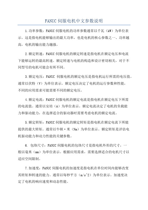
发那科FANCI_αi伺服电机型号参数

Motor ModelαiF 1/5000αiF 2/5000αiF 4/4000αiF 8/3000αiF 12/3000Rated output(kw)0.50.75 1.4 1.63Stalling torque(Nm)124812Max.speed(r/min)50005000500030003000Rotor intertia(kgm 2)0.000310.000530.00140.00260.0062Driver(αi SV)80SpecificationA06B-0202-Bxyz A06B-0205-Bxyz A06B-0223-Bxyz A06B-0227-Bxyz A06B-0243-Bxyz Motor ModelαiF 22/3000αiF 30/3000αiF 40/3000Rated output(kw)476Stalling torque(Nm)223038Max.speed(r/min)300030003000Rotor intertia(kgm 2)0.0120.0170.022Driver(αi SV)80Specification A06B-0247-Bxyz A06B-0253-Bxyz A06B-0257-Bxyz Note 2:Straight shaft with key way3:Taper shaft,with breakA06B-0257-Bxyz x :0:Taper shaft1:Straight shaft1: with Fan (only for aiF 40)2: with High-Torque Brake *14:Straight shaft,with break5:Straight shaft with key way,with breaky :0: standardz :0:Pulsecoder aiA10001:Pulsecoder aiI10002:Pulsecoder aiA160003: with High-Torque Brake , with Fan *1*1): "x" should be from 3 to 5αiF 伺服电机简明规格参数20401609533000αiF 40/3000i with fan 0.022FANUC伺服电机按驱动电压可分为高压电机(400VHV)和低压电机(200V);按产品系列可以分αi系列和βiS系列两大类;这两大系列伺服电机又依次可以分为αiF、αiS、αiF(HV)、αiS(HV)和βiS、βiS(HV)等子类。
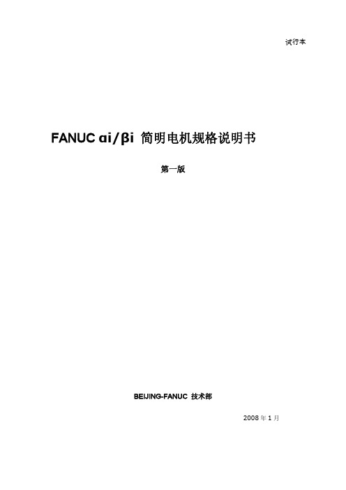
FANUC SERVO MOTOR ais系列(性能参数)

ModelSpecification A06B-0212-B 䂔0䂔(*) The values are the standard values at 20㷄 and the tolerance is ±10%.The speed-torque characteristics very depending on the type of software, parameter setting,and input voltage of the digital servo software. (The above figures show average values.)@2/5000*sModelSpecification A06B-0215-B 䂔0䂔(*) The values are the standard values at 20㷄 and the tolerance is ±10%.The speed-torque characteristics very depending on the type of software, parameter setting,and input voltage of the digital servo software. (The above figures show average values.)@4/5000*sModelSpecification A06B-0235-B 䂔0䂔(*) The values are the standard values at 20㷄 and the tolerance is ±10%.The speed-torque characteristics very depending on the type of software, parameter setting,and input voltage of the digital servo software. (The above figures show average values.)@8/4000*sModelSpecification A06B-0238-B 䂔0䂔(*) The values are the standard values at 20㷄 and the tolerance is ±10%.The speed-torque characteristics very depending on the type of software, parameter setting,and input voltage of the digital servo software. (The above figures show average values.)@12/4000*sModelSpecification A06B-0265-B 䂔0䂔(*) The values are the standard values at 20㷄 and the tolerance is ±10%.The speed-torque characteristics very depending on the type of software, parameter setting,and input voltage of the digital servo software. (The above figures show average values.)@22/4000*sModelSpecification A06B-0268-B 䂔0䂔(*) The values are the standard values at 20㷄 and the tolerance is ±10%.The speed-torque characteristics very depending on the type of software, parameter setting,and input voltage of the digital servo software. (The above figures show average values.)@30/4000*sModelSpecification A06B-0272-B 䂔0䂔(*) The values are the standard values at 20㷄 and the tolerance is ±10%.The speed-torque characteristics very depending on the type of software, parameter setting,and input voltage of the digital servo software. (The above figures show average values.)@40/4000*sModelSpecification A06B-0275-B 䂔0䂔(*) The values are the standard values at 20㷄 and the tolerance is ±10%.The speed-torque characteristics very depending on the type of software, parameter setting,and input voltage of the digital servo software. (The above figures show average values.)@50/3000*sModelSpecification A06B-0275-B 䂔1䂔(*) The values are the standard values at 20㷄 and the tolerance is ±10%.The speed-torque characteristics very depending on the type of software, parameter setting,and input voltage of the digital servo software. (The above figures show average values.)@50/3000*s 䌷䌩䌴䌨䌆䌁䌎ModelSpecification A06B-0285-B 䂔0䂔(*) The values are the standard values at 20㷄 and the tolerance is ±10%.The speed-torque characteristics very depending on the type of software, parameter setting,and input voltage of the digital servo software. (The above figures show average values.)@100/2500*sB-65262EN/03 F ANUC AC SERVO MOTOR αi S SERIES 3.SPECIFICATIONS AND CHARACTERISTICSModelSpecification A06B-0288-B 䂔0䂔(*) The values are the standard values at 20㷄 and the tolerance is ±10%.The speed-torque characteristics very depending on the type of software, parameter setting,and input voltage of the digital servo software. (The above figures show average values.)@200/2500*s3.SPECIFICATIONS AND CHARACTERISTICS F ANUC AC SERVO MOTOR αi S SERIES B -65262EN/03ModelSpecification A06B-0292-B 䂔1䂔(*) The values are the standard values at 20㷄 and the tolerance is ±10%.The speed-torque characteristics very depending on the type of software, parameter setting,and input voltage of the digital servo software. (The above figures show average values.)@300/2000*sB-65262EN/03 F ANUC AC SERVO MOTOR αi S SERIES 3.SPECIFICATIONS AND CHARACTERISTICSModelSpecification A06B-0295-B 䂔1䂔(*) The values are the standard values at 20㷄 and the tolerance is ±10%.The speed-torque characteristics very depending on the type of software, parameter setting,and input voltage of the digital servo software. (The above figures show average values.)@500/2000*s。
FANUCai主轴电机参数表

FANUCai主轴电机参数表FANUC ai 主轴电机参数表1. Type of applied documentsi series PARAMETER MANUALαName FANUC AC SPINDLE MOTORSpec. No./Ver. B-65280EN/012. Summary of ChangeGroupName / Outline New, AddCorrect, Del ApplicableDateBasicFunctionOptionalFunctionUnitMaintenancePartsNoticeCorrectionAnotherTable of parameters for each motor model has been added.Add 2001.12i series spindleα motor Table of parameters for each motor model(1) OutlineiαFor series spindle motor , this manual describes the table of parameters for each motor model and model code. (2) Procedure for spindle parameter initializationPerform automatic spindle parameter initialization by following the procedure below.<1> Set the model code for the desired motor for automatic parameter initialization.In case that there is no model code, set model code 300 (or 400 when the speed range switching function is used) for automatic parameter initialization, then manually change the parameter data according to the table of parameter for each model.Parameter no. Settings15i 16i3133 4133 Model code<2> Set the relevant parameter to 1 to enable automatic spindle parameter initialization.Parameter no. Settings15i 16i- 4019#7 15607#0 - 0NoteThis bit is reset to its original value after automatic parameter intialization.<3> Turn the CNC off/on and the spindle parameters specified with the model code are automatically initialized.<4> In case that there is no model code, manually change the parameter data according to the table of parameter for each model.<5> Set the detector-related parameters according to the configuration of the detector.<6> Turn the CNC and SPM off/on again.Motor model name3/10000iα2/10000i α1.5/10000i α1/10000i α 12/7000iα8/8000i αApplicable amplifier SPM-2.2i SPM-5.5i SPM-5.5i SPM-5.5i SPM-11i SPM-15iModel code (applicable software) 302 (9D50/D) 304 (9D50/D) 306 (9D50/D) 308 (9D50/D) 312 (9D50/D) 314 (9D50/D) Output specificationsParameter No. 1.5/2.2 kW3000/10000 min-1 1.1/3.7 kW1500/10000 min-1 2.2/3.7 kW1500/10000 min-1 3.7/5.5 kW1500/10000 min-1 7.5/11 kW1500/8000 min-1 11/15 kW1500/7000 min-1FS15i FS16i3007 4007 00000000 00000000 00000000 00000000 00000000 000000003008 4008 00000000 00000000 00000000 00000000 00000000 000000003009 4009 00000000 00000000 00000000 00000000 00000000 000000003010 4010 00000000 00000000 00000000 00000000 00000000 000000003011 4011 00011001 00011001 00011001 00011001 00011010 000110103012 4012 10000010 10000010 10000010 10000010 10000010 100000103013 4013 00001100 00001100 00001100 00001100 00001100 000011003019 4019 00000100 00000100 00000100 00000100 00000100 00000100 3020 4020 10000 10000 10000 10000 8000 70003039 4039 0 0 0 0 0 03080 4080 8380*1 8565*1 7770*1 6065*1 75 703083 4083 30 30 30 30 30 303100 4100 3100 1650 1550 1600 1600 1500 3101 4101 100 100 100 100 100 1003102 4102 3557 2767 2567 1967 1656 1500 3103 4103 87*1 60*1 68*1 75*1 0 03104 4104 6000 6000 6000 7000 8000 7000 3105 4105 0 0 0 0 0 03106 4106 6000 6000 6000 7000 8000 7000 3107 4107 0 0 0 0 0 03108 4108 0 0 0 0 0 03109 4109 25 25 25 25 25 253110 4110 690 563 474 475 503 5953111 4111 102 217 175 200 170 1733112 4112 200 200 200 19400 200 200 3113 4113 2100 1635 1192 1077 790 311 3114 4114 17920 0 0 0 19200 230403115 4115 100 100 100 100 100 1003116 4116 10018 9598 9300 7950 8118 5000 3117 4117 90 90 90 28250 90 903118 4118 100 100 100 110 100 1003119 4119 5 5 8 5 12 313120 4120 0 0 0 0 0 03124 4124 0 0 0 0 0 03127 4127 176 404 202 178 176 1643128 4128 0 115 90 0 117 03129 4129 0 0 0 0 0 03130 4130 25700 25700 25700 25700 25700 257003134 4134 110 110 110 110 130 1303169 4169 0 0 0 0 0 0Maximum output at acceleration(for PSM selection) 2.64 kW2.87 kW*1 4.44 kW6.7 kW*1 4.44 kW6.4 kW*1 6.6 kW7.9 kW*1 13.2 kW18.0 kW(*1) If you set these parameters, maximum output at acceleration is larger and acceleration time is shorter. Motor model name2/15000iα40/6000i α30/6000i α22/7000i α15/7000i αApplicable amplifier SPM-22i SPM-26i SPM-45i SPM-45i SPM-22iModel code (applicable software) 316 (9D50/D) 320 (9D50/D) - - 307 (9D50/D)Output specificationsParameter No. 15/18.5 kW1500/7000 min-1 22/26 kW1500/7000 min-1 30/37 kW1150/6000 min-1 37/45 kW1500/6000 min-1 2.2/3.7 kW3000/15000 min-1FS15i FS16i3007 4007 00000000 00000000 00000000 00000000 000000003008 4008 00000000 00000000 00000000 00000000 000000003009 4009 00000000 00000000 00000000 00000000 000000003010 4010 00000000 00000000 00000000 00000000 000000003011 4011 00011010 00011010 00011010 00011010 000110013012 4012 10000010 10000010 10000010 10000000 100000103013 4013 01010000 01010000 00011000 00011000 01010000 3019 4019 00000100 00000100 00000100 00000100 00000100 3020 4020 7000 7000 6000 6000 150003039 4039 0 0 0 0 03080 4080 20555 80 77 80 121223083 4083 30 30 30 30 103100 4100 1500 1500 1387 1740 32003101 4101 95 95 100 100 453102 4102 1710 1756 1387 1740 64323103 4103 0 0 0 0 923104 4104 5500 4500 6000 3000 30003105 4105 0 0 0 0 03106 4106 5500 4500 6000 3000 30003107 4107 0 0 0 0 03108 4108 0 0 0 0 03109 4109 25 25 25 25 253110 4110 794 924 1145 970 5883111 4111 243 252 286 286 1753112 4112 200 200 200 200 2003113 4113 304 290 189 190 18003114 4114 23040 0 20480 23040 03115 4115 100 100 100 100 1003116 4116 5177 5564 6071 6128 165643117 4117 90 29530 90 90 903118 4118 100 110 100 100 1003119 4119 31 29 51 48 23120 4120 0 0 0 0 03124 4124 0 0 0 0 03127 4127 148 142 148 146 2023128 4128 105 105 0 0 853129 4129 0 0 0 0 03130 4130 25700 25700 25700 25700 257003134 4134 130 130 130 130 1103169 4169 0 0 0 0 0Maximum output at acceleration(for PSM selection) 22.2 kW31.2 kW44.4 kW54.0 kW20.0 kW6/12000iαMotor model name α22/10000i αα30/6000i 50/6000i Applicable amplifier SPM-11i SPM-26i SPM-22i SPM-26i Model code (applicable software) 401 - - -Output specificationsParameter No. Low 5.5/7.5 kW1500/12000 min-1High 5.5/7.5 kW4000/12000 min-1 Low 22/26 kW1500/10000 min-1High 22/26 kW4000/10000 min-1 Low 11/18.5 kW400/1500 min-1High 15/18.5 kW575/6000 min-1 Low 22/30 kW575/1500 min-1High 22/30 kW1200/6000 min-1FS15i FS16i3007 4007 00000000 00000000 00000000 00000000 3008 4008 00000000 00000000 00000000 00000000 3009 4009 00000000 00000000 00000000 00000000 3010 4010 00000000 00000000 00000000 00000000 3011 4011 00011010 00011010 00011010 00011010 3012 4012 10000010 10000010 10000010 10000010 3013 4013 00001100 01010000 01010000 01010000 3019 4019 00000100 00000100 00000100 00000100 3020 4020 12000 10000 6000 60003023 4023 333 *2 400 96 2003039 4039 0 0 0 03080 4080 82 75 19280 753083 4083 30 30 30 303093 4093 164 142 202 1643100 4100 4000 4000 590 11073101 4101 81 83 100 1003102 4102 4561 3504 889 11073103 4103 69 0 85 03104 4104 4000 2800 10000 80003105 4105 0 0 0 03106 4106 4000 2800 10000 80003107 4107 0 0 0 03108 4108 0 0 0 03109 4109 25 25 25 253110 4110 431 603 750 6863111 4111 125 143 267 1753112 4112 200 200 150 2003113 4113 650 265 198 1803114 4114 20480 24320 21760 25600 3115 4115 100 100 100 1003116 4116 8986 5523 6050 6150 3117 4117 90 90 90 903118 4118 100 100 100 1003119 4119 15 36 48 533120 4120 0 0 0 03124 4124 0 0 0 03127 4127 164 142 148 1643128 4128 95 0 105 1003129 4129 0 0 0 03130 4130 25700 25700 25700 25700 3134 4134 130 130 130 1303136 4136 30 30 30 303138 4138 1550 1440 400 6083139 4139 96 96 100 1003140 4140 2630 1709 684 6083141 4141 60 96 0 03142 4142 6000 5000 13000 21000 3143 4143 6000 5000 13000 21000 3144 4144 0 0 0 0 3145 4145 25 25 25 253146 4146 754 823 2011 11313147 4147 260 213 733 3173148 4148 200 200 200 2003149 4149 620 300 165 1953150 4150 20480 19200 0 23040 3151 4151 100 100 100 1003152 4152 8803 5593 6008 6191 3153 4153 90 90 28250 903154 4154 100 100 100 1003155 4155 0 0 0 03156 4156 0 0 0 03158 4158 109 0 90 1103159 4159 0 0 0 03161 4161 25700 25700 25700 25700 3165 4165 15 341 58 493166 4166 66 56 50 653169 4169 0 0 0 0Maximum output at acceleration (for PSM selection) 9.0 kW31.2 kW25.0 kW 35.4 kW(*2) If you use the SDT signal, change the parameter data manually after performing automatic spindle parameter initialization。
FANUC伺服电机中文参数说明

FANUC伺服电机中文参数说明1.功率参数:FANUC伺服电机的功率参数通常以千瓦(kW)为单位表示。
这是指电机能够输出的最大功率,也是电机的核心参数之一、功率越高,电机的输出能力越强。
2.额定转速:FANUC伺服电机的额定转速是指电机在额定电压和电流下能够运转的最高转速。
额定转速与电机的构造和设计密切相关,对于不同型号的电机可能会有所不同。
3.额定电压:FANUC伺服电机的额定电压是指电机运行所需的电压值。
通常以伏特(V)为单位表示。
额定电压决定了电机的运行参数和性能,不同的应用需求可能需要不同的额定电压。
4.额定电流:FANUC伺服电机的额定电流是指电机在额定电压下所需的电流值。
通常以安培(A)为单位表示。
额定电流决定了电机的负载能力和驱动能力,在选择适合的驱动器时需要考虑电机的额定电流。
5.额定转矩:FANUC伺服电机的额定转矩是指电机在额定电流下所能提供的最大转矩。
通常以牛顿·米(Nm)为单位表示。
额定转矩是评估电机驱动能力和动力性能的关键参数。
6. 包络尺寸:FANUC伺服电机的包络尺寸是指电机外形的尺寸,一般以毫米(mm)为单位表示。
根据应用需求,需要选择适合的电机尺寸以适应空间限制。
7.加速度:FANUC伺服电机的加速度是指电机在单位时间内能够改变其转矩和转速的能力。
通常以每秒平方(m/s^2)为单位表示。
加速度决定了电机的响应速度和动态性能。
8. 轴径:FANUC伺服电机的轴径是指电机输出轴的直径。
通常以毫米(mm)为单位表示。
轴径决定了电机的安装方式和接口形式,需要根据具体应用需求选择合适的电机轴径。
9. 支持通讯协议:FANUC伺服电机通常支持多种通讯协议,如FANUC伺服协议、EtherNet/IP、Modbus等。
这些通讯协议能够使电机与上位设备进行联动控制和数据传输。
10.配件附件:在使用FANUC伺服电机时,还可以选择各种配件附件,如编码器、刹车器、温度传感器等,以实现更精确的运动控制和故障保护。
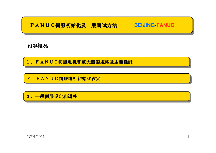
FANUC简明电机规格说明书

试行本FANUCαi/βi 简明电机规格说明书第一版BEIJING-FANUC技术部2008年1月目录1. αi伺服电机规格说明 (5)1.1 αiS伺服电机安装尺寸与功率曲线说明·α2iS、α4iS电机安装尺寸说明·α8iS、α12iS电机安装尺寸说明·αi22S、α30iS、α40iS电机安装尺寸说明·αiS系列电机扭矩曲线说明1.2 αiF伺服电机安装尺寸与功率曲线说明·α4iF、α8iF电机安装尺寸说明·α12iF、α22iF、α30iF、α40iF电机安装尺寸说明·αiF系列电机扭矩曲线说明2. βi伺服电机规格说明 (21)2.1 βiS伺服电机安装尺寸与功率曲线说明·β2iS、β4iS电机安装尺寸说明·β8iS、β12iS电机安装尺寸说明·β22iS电机安装尺寸说明·βiS系列电机扭矩曲线说明3. αi主轴电机规格说明 (31)3.1 αiI主轴电机安装尺寸与功率曲线说明·αiI 3/10000 主轴电机安装尺寸说明·αiI6/10000 主轴电机安装尺寸说明·αiI8/8000 主轴电机安装尺寸说明·αiI12/7000 主轴电机安装尺寸说明·αiI15/7000 主轴电机安装尺寸说明·αiI12/7000 主轴电机安装尺寸说明·αiI18/7000 主轴电机安装尺寸说明·αiI22/7000 主轴电机安装尺寸说明·αiI30/6000 主轴电机安装尺寸说明·αiI40/6000 主轴电机安装尺寸说明·αiI 系列主轴电机功率曲线说明3.2 αiP主轴电机安装尺寸与功率曲线说明·αiP12/6000 主轴电机安装尺寸说明·αiP15/6000 主轴电机安装尺寸说明·αiP18/6000 主轴电机安装尺寸说明·αiP30/6000 主轴电机安装尺寸说明·αiP40/6000 主轴电机安装尺寸说明·αiP系列主轴电机功率曲线说明4. βi主轴电机规格说明 (54)4.1βi主轴电机安装尺寸与功率曲线说明·βiI3/10000 主轴电机安装尺寸说明·βiI6/10000 主轴电机安装尺寸说明·βiI8/8000 主轴电机安装尺寸说明·βiI12/7000 主轴电机安装尺寸说明·βiI系列主轴电机功率曲线说明5. 放大器配置说明 (60)前言FANUC电机可分为“伺服电机”和“主轴电机”两大类。
FANUC伺服电机规格及初始化

(Ap)
驱动放大器
4
4
20 20 20 20 20 20
20 40
40
脉17冲/0编6/码20器11
ABS65,536 /rev
ABS131,072 /rev
3
bbiIiI主主轴轴电电机机
BBEEIJIJININGG--FFAANNUUCC
与αiI 系列比较
αiI series
连续额定扭矩(Nm) 短时间额定 (min.) 额定输出最高转速 (min-1)
BBEEIJIJININGG--FFAANNUUCC
βiS 0.2 βiS 0.3 βiS 0.4 βiS 0.5 βiS 1 βiS 2 βiS 4 βiS 8 βiS 12 βiS 12 βiS 22
/5000 /5000 /5000 /5000 /5000 /4000 /4000 /3000 /2000 /3000 /2000
BBEEIJIJININGG--FFAANNUUCC
2
ββiSiS伺伺服服电电机机
• 外形紧凑适用于小型机械 • 电机平滑旋转实现高精度切削 • 高可靠性、高性价比 • 小型·高分辨率的βi 脉冲编码器(131,072 / rev) • ID信息、温度信息输出到CNC • 高精度工作机械用伺服电机( biS2 ~ biS22 ) • 0i-C, 0iMate-C系统使用
额定输出 (kW) 0.05 0.1 0.13 0.2 0.4 0.5 0.75 1.2 1.4 1.8 2.5
堵转转矩 (Nm) 0.16 0.32 0.4 0.65 1.3
2
3.5
7
11 11 20
最高转速 (min-1) 5000 5000 5000 5000 5000 4000 4000 3000 2000 3000 2000
标签版——FANUC αi βi 简明电机规格说明书 第 版

试行本FANUCαi/βi 简明电机规格说明书第一版BEIJING-FANUC技术部2008年1月目录1. αi伺服电机规格说明 (5)1.1 αiS伺服电机安装尺寸与功率曲线说明·α2iS、α4iS电机安装尺寸说明·α8iS、α12iS电机安装尺寸说明·αi22S、α30iS、α40iS电机安装尺寸说明·αiS系列电机扭矩曲线说明1.2 αiF伺服电机安装尺寸与功率曲线说明·α4iF、α8iF电机安装尺寸说明·α12iF、α22iF、α30iF、α40iF电机安装尺寸说明·αiF系列电机扭矩曲线说明2. βi伺服电机规格说明 (21)2.1 βiS伺服电机安装尺寸与功率曲线说明·β2iS、β4iS电机安装尺寸说明·β8iS、β12iS电机安装尺寸说明·β22iS电机安装尺寸说明·βiS系列电机扭矩曲线说明3. αi主轴电机规格说明 (31)3.1 αiI主轴电机安装尺寸与功率曲线说明·αiI 3/10000 主轴电机安装尺寸说明·αiI6/10000 主轴电机安装尺寸说明·αiI8/8000 主轴电机安装尺寸说明·αiI12/7000 主轴电机安装尺寸说明·αiI15/7000 主轴电机安装尺寸说明·αiI12/7000 主轴电机安装尺寸说明·αiI18/7000 主轴电机安装尺寸说明·αiI22/7000 主轴电机安装尺寸说明·αiI30/6000 主轴电机安装尺寸说明·αiI40/6000 主轴电机安装尺寸说明·αiI 系列主轴电机功率曲线说明3.2 αiP主轴电机安装尺寸与功率曲线说明·αiP12/6000 主轴电机安装尺寸说明·αiP15/6000 主轴电机安装尺寸说明·αiP18/6000 主轴电机安装尺寸说明·αiP30/6000 主轴电机安装尺寸说明·αiP40/6000 主轴电机安装尺寸说明·αiP系列主轴电机功率曲线说明4. βi主轴电机规格说明 (54)4.1βi主轴电机安装尺寸与功率曲线说明·βiI3/10000 主轴电机安装尺寸说明·βiI6/10000 主轴电机安装尺寸说明·βiI8/8000 主轴电机安装尺寸说明·βiI12/7000 主轴电机安装尺寸说明·βiI系列主轴电机功率曲线说明5. 放大器配置说明 (60)前言FANUC电机可分为“伺服电机”和“主轴电机”两大类。
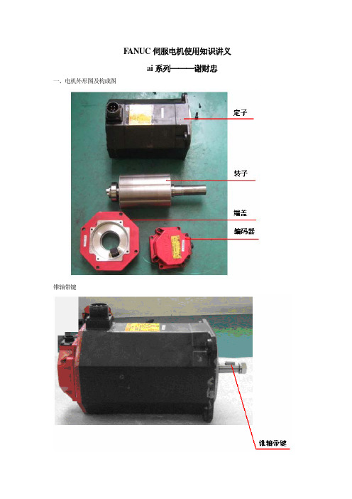
FANU ai伺服电机使用知识

FANUC伺服电机使用知识讲义ai系列———谢财忠一、电机外形图及构成图锥轴带键光直轴直轴带键说明:如用户自已换轴承,并把前法兰拆下过,或发现定子铁芯与前法兰有明显错位痕迹,如要送最好提前告诉用户必须更换定子,因为前法兰定子铁芯与前法兰安装时有同心度要求,出厂时定子铁芯与前法兰是组成一个整体部件的,新电机如电机轴盘不动或运转时有异音,仔细观察一下定子铁芯与前法兰接合部的漆痕变化,有可能用户在安装及搬运时摔伤过电机。
二、电机型号及规格号:伺服电机aiS表示稀土材料伺服电机。
S表示强磁稀土材料Strong ai、aiF表示铁氧体材料伺服电机。
F表示氧化铁 FerrITe ßiS表示稀土材料伺服电机。
LiS表示直线伺服电机。
S表示强磁稀土材料DiS表示内装伺服电机S表示强磁稀土材料ai、aiS电机是由使用AC200-230V的放大器驱动的。
a(HV)i、a(HV)is电机是由使用AC400-460V的放大器驱动的。
三、电机编码器在电机的后端装有编码器,用来检测电机的转速及作为位置检测信号。
S系列电机用编码器信号表电机零位定义:1、电机动力插座U相接+,V、W相接-。
2、C1、C2、C4、C8用示波器测量为高电平。
ai系列电机信号表串行信号RD、*RD包含有A、*A、B、*B、Z、*Z、C1、C2、C4、C8信号。
说明:a6、a8i、β8i以下电机,更换轴承,必须把转子上的金属欧式联轴节拆下来,才能更换后 轴承,因此如用户自行更换轴承,有可能因为电机零位错误出现410、411报警,因此不建议用户自 已更换轴承。
四、制动器制动器特性见表:制动器连接管脚图电机型号a1i-a2i、a2is-a4is电机型号a4i-a40i、a8is-a200is其中4脚需要与电缆的屏蔽相连。
连接制动器(1)、不能与NC和放大器共用一个直流24V电源。
(2)、可以通过变压器全波整流成直流24V为制动器供电,但不能使用半波整流器。
标签版FANUCαiβi简明电机规格说明书第版

试行本FANUCαi/βi 简明电机规格说明书第一版BEIJING-FANUC技术部2008年1月目录1. αi伺服电机规格说明 (5)1.1 αiS伺服电机安装尺寸与功率曲线说明·α2iS、α4iS电机安装尺寸说明·α8iS、α12iS电机安装尺寸说明·αi22S、α30iS、α40iS电机安装尺寸说明·αiS系列电机扭矩曲线说明1.2 αiF伺服电机安装尺寸与功率曲线说明·α4iF、α8iF电机安装尺寸说明·α12iF、α22iF、α30iF、α40iF电机安装尺寸说明·αiF系列电机扭矩曲线说明2. βi伺服电机规格说明 (21)2.1 βiS伺服电机安装尺寸与功率曲线说明·β2iS、β4iS电机安装尺寸说明·β8iS、β12iS电机安装尺寸说明·β22iS电机安装尺寸说明·βiS系列电机扭矩曲线说明3. αi主轴电机规格说明 (31)3.1 αiI主轴电机安装尺寸与功率曲线说明·αiI 3/10000 主轴电机安装尺寸说明·αiI6/10000 主轴电机安装尺寸说明·αiI8/8000 主轴电机安装尺寸说明·αiI12/7000 主轴电机安装尺寸说明·αiI15/7000 主轴电机安装尺寸说明·αiI12/7000 主轴电机安装尺寸说明·αiI18/7000 主轴电机安装尺寸说明·αiI22/7000 主轴电机安装尺寸说明·αiI30/6000 主轴电机安装尺寸说明·αiI40/6000 主轴电机安装尺寸说明·αiI 系列主轴电机功率曲线说明3.2 αiP主轴电机安装尺寸与功率曲线说明·αiP12/6000 主轴电机安装尺寸说明·αiP15/6000 主轴电机安装尺寸说明·αiP18/6000 主轴电机安装尺寸说明·αiP30/6000 主轴电机安装尺寸说明·αiP40/6000 主轴电机安装尺寸说明·αiP系列主轴电机功率曲线说明4. βi主轴电机规格说明 (54)4.1βi主轴电机安装尺寸与功率曲线说明·βiI3/10000 主轴电机安装尺寸说明·βiI6/10000 主轴电机安装尺寸说明·βiI8/8000 主轴电机安装尺寸说明·βiI12/7000 主轴电机安装尺寸说明·βiI系列主轴电机功率曲线说明5. 放大器配置说明 (60)前言FANUC电机可分为“伺服电机”和“主轴电机”两大类。
主轴电机参数表

5000
5000
298
0.5
390
186-□NT…
29.6
38
500
4800
4000
5000
565
0.67
460
186-□ND…
51
77
1000
5000
3850
5000
487
0.67
460
186-□NE…
60
84
1250
5000
3580
5000
458
0.67
460
224-□NC…
55
78
700
3020
2170
4500
750
1.48
650
224-□ND…
71
114
1000
4500
3730
4500
678
1.48
650
224-□NF…
100
140
1500
4500
3890
4500
636
1.48
650
0.128
143
α22
22
26
1500
6000
6000
140.0
0.128
143
α30
30/22
37/26
1150
3500
4500
249.1
0.295
250
α40
37/26
45/30
1500
4000
6000
235.5
0.355
290
αP8
3.7
5.5
750
6000
最新FANUC Alpha系列伺服电机

FANUC Alpha系列伺服电机1. FANUC 的交流伺服电机与直流伺服电机相比,交流伺服伺服电机具有免维护,低损耗,体积小的特点,在现代控制领域已经逐步取代了直流伺服电机,交流伺服电机被广泛地应用到各个控制领域,FANUC 从80年代开始逐步使用交流伺服电机,从开发应用到目前被广泛使用的Alpha 系列伺服电机,经过了三代的更新,从模拟的交流控制单元驱动的伺服电机,到S系列电机,从而又发展成为现在使用的交流Alpha 系列伺服电机,从伺服电机的性能上得到了提高,而电机的体积更小,特别是现在使用的Alpha 系列的伺服电机,电机的型号更全,并采用了磁更强的材料,伺服电机的反馈使用了高速高精度的串行位置编码器,可以适用于各种不同的丝杠而不需要选定编码器的线数,并且该系列具有标准系列,小惯量系列,中惯量系列,经济型的AC系列和高压(380V)的HV系列电机等。
请参考下表:(1) 交流伺服电机的结构目前,在控制领域中所采用的交流伺服电机一般为同步电机(无刷直流电机),电机主要由三部分组成,即:定子,转子,和检测元件构成,其中定子与普通的交流感应电机基本相同,主要有定子冲片,三相绕组线圈,另外还有支撑转子前后端盖和轴承等组成,伺服电机的转子主要由多对极的磁钢,定子冲片和电机轴构成,检测元件由安装在电机尾端的位置编码器构成,目前Alpha系列的电机的编码器使用的是串行脉冲编码器,由于电机的激磁必须和转子的磁极位置垂直,所以电机的位置反馈要能够把电机的磁极位置反馈给伺服系统,用以产生交流伺服电机的激磁的矢量控制。
电机的结构如图4-1所示。
图4-1 交流伺服电机的结构交流伺服电机的工作原理实际上与电磁式的同步电机类似,只不过磁场不是由转子中的激磁绕组产生,而是由作为转子的永久磁铁产生,当定子三相绕组通上交流电源后,电机中就会产生一个旋转的磁场,该磁场将以同步转速Ns旋转。
根据磁场的特性,定子的旋转磁极总是要和转子的旋转磁极相互吸引,并带着转子一同地转动,使定子磁场的轴心线与转子磁场的轴心线保持一致,形成电机的旋转扭矩。
- 1、下载文档前请自行甄别文档内容的完整性,平台不提供额外的编辑、内容补充、找答案等附加服务。
- 2、"仅部分预览"的文档,不可在线预览部分如存在完整性等问题,可反馈申请退款(可完整预览的文档不适用该条件!)。
- 3、如文档侵犯您的权益,请联系客服反馈,我们会尽快为您处理(人工客服工作时间:9:00-18:30)。
Powerful brake
A powerful brake with an increased holding torque is available as an option. The brake uses an asbestos-free design.
- 161 -
2.TYPES OF MOTORS AND DESIGNATION FANUC AC SERVO MOTOR αi SERIES B-65262EN/03
78[N] (8[kgf]) 196[N] (20[kgf])
Front bearing (reference) 6003
6205
1960[N]
588[N]
(200[kgf]) (60[kgf])
6208
For details on these items, refer to "I-2.3.2 Allowable Axis Load for a Servo Motor".
Compact
The use of the latest ferrite magnet, combined with an optimized mechanical design, reduces both the overall length and weight. The result is compact, lightweight servo motors.
Shaft dia. runout
Max. 0.02mm
Max. 0.02mm
Rabbet dia.
eccentricity
Max. 0.04mm
Max. 0.04mm
Mounting face
runout
Max. 0.05mm
Max. 0.05mm
Max. 0.03mm
Max. 0.05mm
Max. 0.06mm
y 0: 1: 3: 4:
Taper shaft Straight shaft Taper shaft with the 24VDC brake Straight shaft with the 24VDC brake
z 0 : Pulsecoder α1000iA 1 : Pulsecoder α1000iI 2 : Pulsecoder α16000iA
• Heat protection • Mounting method
: TP211 : IMB5, IMV1, IMV3
For details on these items, refer to "I-2.1 Environment to use the servo motor", "I-4.2 Specifications of approval servo motors".
2
TYPES OF MOTORS AND DESIGNATION
The types and specifications of αi series servo motors are described as follows.
Models
α1/5000i, α2/5000i, α4/4000i, α8/3000i, α12/3000i, α22/3000i, α30/3000i, and α40/3000i
Excellent acceleration characteristics
The rotor inertia has been reduced without sacrificing maximum output torque. As a result, the motors offer excellent acceleration characteristics.
This chapter describes the specifications and characteristics of FANUC AC servo motor αi series. First section describes the common specifications to all motors, and next section describes the individual specifications and characteristics in the form of data sheet.
Motor Model
α1/5000i α2/5000i α4/4000i α8/3000i α12/3000i α22/3000i α30/3000i α40/3000i α40/3000i with fan
Radial load
245[N] (25[kgf]) 686[N] (70[kgf])
Axial load
Extended continuous-operation
High-density winding, low iron loss by the optimum core shape, and the use of the latest servo software reduce heat generation during high-speed rotation to a minimum and allow a wide continuous operating zone.
Smooth rotation
Further improvements have been made to the unique magnetic pole shape to minimize torque ripple. The result is extremely PECIFICATIONS AND CHARACTERISTICS FANUC AC SERVO MOTOR αi SERIES B-65262EN/03
Shaft runout precision
Motor Model
α1/5000i α2/5000i α4/4000i α8/3000i α12/3000i α22/3000i α30/3000i α40/3000i α40/3000i with fan
For these models, a tapered shaft is standard.
- 162 -
B-65262EN/03 FANUC AC SERVO MOTOR αi SERIES 2.TYPES OF MOTORS AND DESIGNATION
Model α40/3000i with fan A06B-0257-By1z
This section describes the common specifications to FANUC AC servo motor αi series.
• Ambient temperature : 0°C to 40°C
• Ambient humidity : 80%RH or less (no dew)
3.2
CHARACTERISTIC CURVE AND DATA SHEET
This section describes the individual specifications and characteristics of FANUC AC servo motor αi series.in the form of data sheet. For details on these items, refer to "I-3.4 Characteristic curve and data sheet".
A06B-02xx-By0z
xx 02 : 05 : 23 : 27 : 43 : 47 : 53 : 57 :
Model α1/5000i Model α2/5000i Model α4/4000i Model α8/3000i Model α12/3000i Model α22/3000i Model α30/3000i Model α40/3000i
• Installation height : Up to 1,000 meters above the sea level
• Ambient vibration : Not exceed 5G
• Insulation class
: Class F
• Protection type
: IP65
• Cooling method
For details on these items, refer to "I-2.3.3 Shaft runout precision of the servo motor".
- 166 -
B-65262EN/03 FANUC AC SERVO MOTOR αi SERIES 3.SPECIFICATIONS AND CHARACTERISTICS
III. FANUC AC SERVO MOTOR αi SERIES
B-65262EN/03
FANUC AC SERVO MOTOR αi SERIES
1.GENERAL
1
GENERAL
The FANUC AC servo motor αi series consists of a range of servo motors that are suitable for the feed axes of machine tools. They have the following features:
:
Motor Model α40/3000i with fan αi series except above
IC code IC416 IC410
Method
Fully closed Cooled by air flow of a detached fan Fully closed Cooled by a natural air flow
