新一代蜂群恒温加热器
eQ-3 CC-RT-M-BLE-EQ 蓝牙智能散热器恒温器使用说明书

Operating ManualBLUETOOTH SmartRadiator ThermostatUKCC-RT-M-BLE-EQDocumentation © 2018 eQ-3 AG, GermanyAll rights reserved.Translation from the original version in German.153855Version 1.0 (05/2018)1. Information about this manualPlease read this manual completely and carefully before starting touse the device. The manual contains important information about theintended use of the device. Especially observe the safety notes. Keepthe manual for later consultation. If you hand over the device to otherpersons for use, please hand over this manual as well.Symbols used:Attention! This indicates a hazard.Note. This section contains important additional information.2. Package contents1x radiator thermostat1x adapter Danfoss RA1x adapter Danfoss RAV1x spigot extension Danfoss RAV1x adapter Danfoss RAVL1x support ring1x nut M41x cylinder head screw M4 x 12 mm2x 1.5 V mignon/LR6/AA2x operating manual (English and German)3. Device overviewA Bar chart of programmed heating phasesB Eco/comfort temperature (), open-window function(), manual mode (Manu), automatic mode (Auto)C Holiday function (), week day, empty battery symbol()D Mode/Menu button: Switch between auto mode, manu modeand holiday function (press button briefly); open setup menu(press button for at least 3 seconds)E Control wheel: Change settings, e.g. temperature (turn the con-trol wheel), activate the boost function and confirm/save set-tings in the menu (press control wheel briefly)F Union nut for fitting on the heating valveG Display of temperature, time and date, menu options, functionsH button: Switch between eco and comforttemperature4. FunctionThe electric BLUETOOTH® Smart Radiator Thermostat offers individualcontrol of the room temperature from a user-friendly and intuitive app.The app “calor BT” is available for free for iOS and Android smart-phones. The radiator thermostat enables the regulation of single ra-diators or the room temperature.Thanks to pre-programmed or individually tailored heating and cool-ing phases, the desired temperature can be comfortably adjusted.The radiator thermostat fits to all common radiator valves and is easy tomount - without having to drain any water or intervene in the heatingsystem. The additional boost function enables quick, short-term radia-tor heating by opening the valve for 5 minutes. This immediately bringsa comfortable warming to the room. Thanks to the automatic “openwindow detection”, additional energy can be saved during ventilation.5. Intended useThe radiator thermostat is used to control a conventional radiatorvalve. Only operate the device in inside rooms and avoid the influ-ence of moisture, dust and sunlight or external heat radiation. Usingthe device for any purpose other than that described in this operatingmanual does not fall within the scope of intended use and shall inval-idate any warranty or liability. This also applies to any conversion ormodification work.The device is intended for private use only.eQ-3 AG hereby declares that this device complies with the essentialrequirements and other relevant regulations of Directive 1999/5/EC.You can find the full declaration of conformity at www.eQ-3.de.6. Safety instructionsThe device is not a toy; do not allow children to play with it.Do not leave packaging material lying around. It can bed a n-gerous in the hands of a child.Do not open the device: it does not contain any componentsthat need to be serviced by the user. In the event of failure,please have the device checked by an expert.7. Disposal instructionsDo not dispose of the device with regular domestic waste!Electronic equipment must be disposed of at local collectionpoints for waste electronic equipment in compliance with theWaste Electrical and Electronic Equipment Directive.The CE sign is a free trading sign addressed exclusively to theauthorities and does not include any warranty of any proper-ties.Used batteries should not be disposed of with regular do-mestic waste! Instead, take them to your local batterydisposal point.8. Inserting (replacing) batteriesUpon delivery, the batteries are already inserted with an insu-lation strip. For the device to function, please remove this strip.• Press the battery compartment cover on both sides with your fin-gers and pull it away from the device body.• Insert 2 new LR6/mignon/AA (1.5 V) batteries in the batterycompartment, making sure they are the right way round.• Reattach the battery compartment cover and latch it into place.The service life of new alkaline batteries is approximately 2 years.A battery symbol () on the display indicates that the batteriesneed to be replaced. After removing the empty batteries, waitapprox. 1 minute before inserting the new ones. Operation withrechargeable batteries is not possible.Never recharge standard batteries. Doing so will present a riskof explosion. Do not throw the batteries into a fire. Do notshort-circuit batteries.9. Set date and timeAfter inserting batteries, the date and time is automatically request-ed after a brief display of the firmware version number and short mo-tor run (“InS”).• Set the year, month, day, hour and minute with the control wheeland confirm by pressing the control wheel briefly (E).You can adjust the time and date in the menu under “dAt”.The motor moves the control pin backwards during the setting ofdate and time.• If “InS” and the rotating activity symbol “” are displayed, themotor still reverses. When only “InS” is shown in the display, theradiator thermostat can be installed on the valve.The week program and other settings can be adjusted beforeinstallation. Press the Mode/Menu button for this, while “InS”is shown in the display. You will find further information in chap-ter “13. Operation and configuration”.• After the programming has been completed, “InS” is shown againin the display and installation can take place.The union nut attached to the radiator thermostat can be used uni-versally and without accessories for valves of the most popular man-ufacturers with a thread size of M30 x 1.5 mm.• Rotate the thermostat dial to the maximum value (anti-clockwise).The thermostat dial then no longer presses against the valve spin-dle, making it easier to remove.• Remove the mechanical thermostat head. If required, place thesupplied support ring or adapter first.• Attach the radiator thermostat to the valve.10.1 Adapters for DanfossBy means of the adapters included in the package, the device can beinstalled on radiator valves of types Danfoss RA, RAV and RAVL.The assignment of the suitable adapter ring to the relevant valve canbe found in the following illustrations.The Danfoss valve bodies have elongated notches (I) around their cir-cumference (see arrow), which also ensure that the adapter is properlyseated when it snaps on.If required, place the provided support ring (L) into the flangebefore installing the radiator thermostat.During installation, please ensure that the pins inside the adapt-er (J) are lined up with the notches (I) on the valve. Ensure thatthe adapter is properly clipped on.Take care during installation that you do not trap your fingersbetween the two halves of the adapter!The RA and RAV adapters have been manufactured with pre-tensionin order to provide a better seat. Use a screwdriver during installationif necessary, and bend it open slightly in the vicinity of the screw. Af-ter clipping onto the valve body, please attach the adapter using theprovided screw and nut.The spigot extension (K) must be fitted to the valve pin of RAV valvesprior to installation.IJKThe adapter RAVL does not have to be screwed.I10.2 Support ringThe valves from different manufacturers may have tolerance fluctu-ations that make the radiator thermostat more loosely seated on thevalve. In this case, the provided support ring (L) should be placed intothe flange before installing the radiator thermostat.11. Adaption runAfter inserting batteries and mounting on the valve an adapting run(“AdA”) is performed to adapt to the valve.• As soon as the radiator thermostat has been mounted to the valve,press the control wheel when “InS” is displayed.operation is possible.If the adaption run has been initiated prior to installing or if anerror message (F1, F2, F3) is displayed, press the Boost button;the motor reverses to the “InS” position.EN12. Display content in normal modeSwitching time periods, operating mode, set-point temperature and weekday are displayed in normal mode. The bars for switching time periods of the week program are displayed for every second time interval.13. Operation and configurationAfter the radiator thermostat has been mounted and set up, the device can be individually operated and configured. Operation and configu-ration can be performed either via BLUETOOTH ® with the app “calor BT” or directly on the device.13.1 Operation and configuration via appTo control the device via app, please proceed as follows:• Download the app “calor BT” from the iOS or Android store andinstall the app on your smartphone.• Follow the instructions in the app.Afterwards, you can control and configure the radiator thermostat via the app.13.2 Operation and configuration on the deviceOperation and configuration can be performed directly on the de-vice. Therefore, please proceed as described in the following sections.13.2.1 Setting the program for the week (Pro)For each day, up to 3 heating phases (7 change settings) can be set sep-arately. The programming is carried out for the selected days, where-by temperature settings have to be set for the entire period between 00:00 and 23:59.The device is pre-programmed with a schedule for the week (see sec-tion 11.1). To set your own schedule, please follow these instructions:• Press the Mode/Menu button for at least 3 seconds. The displaywill show “Pro”. Confirm by pressing the control wheel briefly.• “dAy” appears on the display. You can use the control wheel toselect a single day of the week, all weekdays, the weekend, or the entire week.• Confirm by pressing the control wheel briefly.• The first switching time point is displayed (00:00). This cannot bechanged. The heating times are displayed as bars. • Confirm by pressing the control wheel briefly.• Set the temperature which is desired from 0:00. • Confirm by pressing the control wheel briefly.• The next switching time point is displayed. You can adjust this byrotating the control wheel.• Finally set the temperature which should prevail from the select-ed time.• You can repeat this procedure until all the other desired temper-atures for the time period from 0:00 to 23:59 have been stored.• If all 7 switching time points have been allocated, 23:59 is displayedas the final switching point to be confirmed.In auto mode, the temperature can be changed at any time using the control wheel. The modified temperature will then remain the same until the next point at which the program changes.13.2.2 Setting date and time (dAt)Date and time can be adjusted via the menu at any time.• Press the Mode/Menu button for at least 3 seconds.• Select the menu item “dAT” with the control wheel.• Set the year, month, day, hour and minute with the control wheeland confirm by pressing the control wheel briefly.13.2.3 Switching between summer and winter time (dSt)The automatic switching between summer and winter (and vice versa) on the agreed European date occures in the early hours of the Sunday. The automatic switching is activated in the factory settings. It can be manually deactivated as below:• Press the Mode/Menu button for at least 3 seconds.• Select the menu item “dSt” with the control wheel.• Confirm by pressing the control wheel briefly.• The display will show “OFF” to deactivate the function or “On” toactivate the function.• Confirm by pressing the control wheel briefly.13.2.4 Open-window function (AEr)With a rapidly reducing temperature, the radiator thermostat automat-ically detects that a room is being ventilated. In order to save heating costs, the temperature is then reduced for a certain period of time (15 minutes, set at the factory). Whilst this function is active, the “window open” symbol ( ) appears on the display.• Press the Mode/Menu button for at least 3 seconds.• Select the menu item “AEr” with the control wheel and confirmby pressing the control wheel briefly.• The temperature and time can be set with the control wheel. Thefunction can be deactivated by selecting “0” for the time.13.2.5 Setting offset temperature (tOF)As the temperature is measured on the radiator, the temperature dis-tribution can vary throughout a room. To adjust this, a temperature offset of up to ±3.5 °C can be set. If a nominal temperature of e.g. 20 °C is set but the room presents with only 18 °C, an offset of -2.0 °C needs to be set.• Press the Mode/Menu button for at least 3 seconds.• Select the menu item “tOF” with the control wheel and confirmby pressing the control wheel briefly.• Turn the control wheel for as long as necessary until the desiredtemperature appears.• Confirm by pressing the control wheel briefly.13.2.6 Activate/deactivate BLUETOOTH ® (bLE)The BLUETOOTH ® function of the radiator thermostat can be activat-ed or deactivated manually.• Press the Mode/Menu button for at least 3 seconds.• Select the menu item “bLE” with the control wheel and confirmby pressing the control wheel briefly.• The display will show “OFF” to deactivate the function or “On” toactivate the function.• Confirm by pressing the control wheel briefly.13.2.7 Restore factory settings (rES)The factory settings of the radiator thermostat can be restored man-ually. If you do this, you will lose all your settings.• Press the Mode/Menu button for at least 3 seconds.• Select the menu item “rES” with the control wheel and confirm bypressing the control wheel briefly.• “COnF” then appears in the display.• Confirm by pressing the control wheel briefly.13.2.8 Boost functionIf, for example, you arrive home earlier than usual, the boost function will help you to heat the room up quickly. When activating the boost function, the heating valve is immediately opened to 80 % for 5 min-utes. The heating of a room takes longer than 5 minutes, but the heat given off by the radiator can be felt immediately.• Press the control wheel briefly to activate the boost button.• The remaining time for the function will be counted down in sec-onds (“b300” to “b000”).• After these 5 minutes have elapsed, the actuator changes to themode which was previously active (auto/manu) with the previous-ly set temperature.• The function can be deactivated prematurely at any time by press-ing the control wheel again.The boost function will not have an immediate effect if the ra-diator is covered or concealed (e.g. by a sofa). The open-window function is deactivated while the boost function is active.13.2.9 Setting the holiday functionIf you want to maintain a fixed temperature for a certain period, e.g. during your holidays or a party, the holiday function can be used.• Briefly press the Mode/Menu button repeatedly, until the suitcasesymbol () appears in the display.• Change the time until which the temperature shall remain with thecontrol wheel and confirm by pressing the control wheel briefly.• Then set the date and confirm by pressing the control wheel briefly.• Set the temperature and confirm by pressing the control wheelbriefly.The set temperature will remain until the set end time. Afterwards, the radiator thermostat will switch back to auto mode.13.2.10 Comfort and eco temperatureVia the comfort and eco temperature button () you can change be-tween these two temperatures. The factory setting for the comfort temperature is 21.0 °C and the eco temperature 17.0 °C.•Press and hold the comfort/eco temperature button () for atleast 3 seconds.• The sun symbol () and the currently stored comfort tempera-ture appear in the display.• Change the temperature with the control wheel and confirm bypressing the control wheel briefly.•The moon symbol () and the currently stored eco temperatureappear in the display.• Change the temperature with the control wheel and confirm bypressing the control wheel briefly.Even in auto mode, the temperature can be changed at any time using the button. It will then remain the same until the next point at which the program changes.13.2.11 Activate heating pause (battery saving)Battery life can be prolonged by switching the heating off in summer. To achieve this, the valve is opened fully. The calcification protectioncontinues to run.In order to save on battery life, you can also deactivate the BLUE-TOOTH ® function (see section “13.2.6 Activate/deactivate Blue-tooth ® (bLE)”).To activate the heating pause, proceed as follows:• Turn the control wheel in manu mode (Manu ) to the right until“On” appears in the display.• To end it, exit the manu mode (Manu ) or turn the selector dialto the left.13.2.12 Set frost protection modeIf a room is not to be heated, the valve can be closed. The valve is only opened if there is a risk of frost. The calcification protection contin-ues to run.• Turn the control wheel in manu mode (Manu ) to the left until “OFF”appears in the display.• To end it, exit the manu mode (Manu ) or turn the control wheelto the right.13.2.13 Child safeguard/operating lock The operation of the device can be locked.• To activate/deactivate the operating lock, press the Mode/Menuand button at the same time.• After it has been successfully activated, “LOC” appears in the display.• To deactivate the operating lock, press both buttons again.14. Troubleshooting and maintenanceError code on thedisplay ProblemSolution Battery symbol()Battery output too lowReplace batteries F1Valve drive sluggish Check installation,check the heating valveF2Actuating rangetoo wide Please checkmounting of the radiatorthermostat F3Adjustment rangetoo smallCheck the heating valveThe radiator thermostat performs a routine descaling run once a week on Saturday at 12:00 to protect against calcification of the valve. During this, “CAL” appears in the display.15. Technical dataDevice short description: CC-RT-M-BLE-EQ Supply voltage: 2x 1.5 V LR6/mignon/AA Current consumption: 100 mA max.Battery life: 2 years (typ.)Degree of protection: IP20Degree of pollution: 2Ambient temperature: 5 to 35 °C Surface temperature: 90 °C (at the radiator)Display: LCD Connection: M30 x 1.5 mm Method of operation: Type 1Linear travel: 4.3 mm Dimensions (W x H x D): 58 x 63 x 122 mm Weight: 176 g (incl. batteries)Radio frequency: 2.402 GHz - 2.480 GHz Open area RF range: 10 m (typ.)Subject to technical changes.The BLUETOOTH ® word mark and logos are registered trademarks owned by Bluetooth SIG, Inc. and any use of such marks by eQ-3 AG is under license. Oth-er trademarks and trade names are those of their respective owners.。
电孵化箱原理
电孵化箱原理电孵化箱是一种利用电能进行温度控制,以达到孵化卵的目的的设备。
它的原理是通过电加热产生热量,再利用温度传感器和控制器来维持适宜的孵化温度。
电孵化箱主要由加热器、温度传感器、控制器和孵化箱体组成。
加热器是电孵化箱的核心部件,它通过电能转化为热能,并将热能传递给孵化箱体。
温度传感器用于实时监测孵化箱内的温度,将温度信号传递给控制器。
控制器根据温度传感器的信号,通过控制加热器工作时间和功率来调节孵化箱内的温度。
孵化箱体是一个密封的空间,用于放置孵化的卵和维持恒定的温度。
电孵化箱的工作原理是通过控制加热器的工作时间和功率来调节孵化箱内的温度。
当孵化箱内的温度低于设定温度时,控制器会发送指令使加热器工作,加热器产生的热能会传递给孵化箱体,提高温度。
当温度达到设定温度时,控制器会停止加热器的工作,以避免温度过高。
通过不断地调节加热器的工作时间和功率,控制器可以保持孵化箱内的温度在适宜的范围内。
电孵化箱的温度控制精度取决于温度传感器的精度和控制器的调节能力。
通常情况下,电孵化箱的温度控制精度可以达到±0.1摄氏度。
这种高精度的温度控制可以有效地保证卵的孵化成功率。
电孵化箱的应用范围广泛。
它可以用于家禽、水产等动物的孵化,也可以用于植物的育苗。
电孵化箱具有温度控制精度高、操作简便、节省空间等优点,因此得到了广泛的应用。
然而,电孵化箱也有一些局限性。
首先,它对电能的供应有一定的要求,需要稳定的电压和电流。
其次,电加热产生的热量可能会导致孵化箱内部的湿度过低,需要额外的湿度控制装置来调节湿度。
此外,电孵化箱的价格相对较高,对于一些规模较小的养殖户来说可能不太经济实惠。
电孵化箱是一种利用电能进行温度控制的设备,通过控制加热器的工作时间和功率来调节孵化箱内的温度,从而实现卵的孵化。
它具有温度控制精度高、操作简便等优点,被广泛应用于动植物的孵化过程中。
然而,它也存在一些局限性,需要稳定的电能供应和额外的湿度控制装置。
Mecanair HA24-75M 重型强风吸引电子吊顶加热器说明书
INSTRUCTION MANUALHEAVY-DUTY FAN-FORCED CEILING-MOUNT HEATERMODEL: HA24-75MPET OWNERS WARNING : The health of some small pets includingbirds are extremely sensitive to the fumes produced during the first-time use of many appliances. These fumes are not harmful to humans but werecommended that you do not use your heater around birds and small pets during its initial use until the manufacturing corrosion (anti-corrosion) coatings burn off.Technical Support: 1-866-206-0888 Serviceemail:*****************Figure 1TABLE OF CONTENTS Important Instructions (3)Description and Specifications (4)General Safety Information (5)Locating heater (6)Installation........................................................7-9 Co nnecting the power........................................9-12 Operating Instructions.......................................13-14 Maintenance Instructions (14)IMPORTANT INSTRUCTIONSWhen using electrical appliances, basic precautions should always be followed to reduce the risk of fire, electric shock, and injury to persons, including the following:1. Read all instructions before installing or using this heater.2. This heater is hot when in use. To avoid burns, do not let bare skin touch hot surfaces.Keep combustible materials, such as furniture, pillows, bedding, papers, clothes andcurtains at least 3 feet (0.9 m) from the front of the heater and keep them away from the sides and rear.3. Extreme caution is necessary when any heater is used by or near children or invalids andwhenever the heater is left operating and unattended.4. Always turn off the power of heater when not in use.5. Do not operate any heater after it malfunctions, had been dropped or damaged in anymanner. Disconnect power at service panel and have heater inspected by a reputableelectrician before reusing.6. Do not use outdoors.7. This heater is not intended for use in bathrooms, laundry areas and similar indoorlocations. Never locate heater where it may fall into a bathtub or other water container.8. To disconnect heater, turn controls to off, and turn off power to heater circuit at maindisconnect panel.9. Do not insert or allow any foreign objects to enter any ventilation or exhaust opening asthis may cause an electric shock or fire, or damage the heater.10. To prevent a possible fire, do not block air intakes or exhaust in any manner. Do not useon soft surfaces, like a bed, where openings may be blocked.11. A heater has hot and arcing or sparking parts inside. Do not use it in areas wheregasoline, paint, or flammable liquids are used or stored.12. All wiring must be carried out by a certified electrician and comply with national and localelectrical codes in the United States and Canada.13. Use this heater only as described in this manual. Any other use not recommended by themanufacturer may cause fire, electric shock, or personal injury.14. This heater may include a visual alarm to warn that parts of the heater are gettingexcessively hot. If the alarm turns on, immediately turn the heater off and inspect for any objects on or adjacent to the heater that may have blocked the airflow or otherwisecause high temperatures. DO NOT OPERATE THE HEATER WITH THE ALARMILLUMINATING.SAVE THESE INSTRUCTIONS2DESCRIPTIONThe heavy-duty electric heater is designed for garages, workshops and similar locations. It features two heat settings, for a maximum heat production of 25,589 BTU per hour. It includes horizontal and vertical air flow and a built-in thermostat with overheating safety thermal cut out.SPECIFICATIONSCircuit diagram Figure 2Warning: This appliance must be grounded!Warning: The appliance must be connected to a 45-Amp current protection circuit or device before being connected to power supply!3GENERAL SAFETY INFORMATION: This heater requires a hardwire installation (no plug). The installation ofthis product must be carried out by a certified electrician and in accordance with all local and national electrical codes.NOTE: This appliance is compatible with a 240V line voltage single pole wall thermostat(not included). This heater must be installed by a certified electrician.Read and understand all installation and operation instructions prior tooperating this unit. Observe all safety instructions at all times. 1. Use only copper wires rated for at least 60ºC.2. Heater air flow must be directed parallel to or away from adjacent wall.3. Observe wall, floor and ceiling clearance requirements.4. All wiring must be done according to national and local electrical codes in the United States and Canada. The heater must be grounded as a precaution against possible electrical shock. Heater circuit must be protected with proper fuses.5. The mounting structure and the anchoring hardware must be capable of supporting the weight of the heater and the mounting bracket (if used).6. All electrical power must be disconnected and the main service box, which must be locked before connecting, inspecting, cleaning or servicing the heater. This is a precaution to prevent serious electric shock.7. This heater is not suitable for use in hazardous locations as defined by the national fire protection association (NFPA) in the United States. This heater has hot and arcing sparking parts inside. Do not use it in areas where gasoline paint or flammable liquids are used or stored.8. This heater is not suitable for use in corrosive atmospheres such as marine greenhouses or chemical storage areas.9. This heater must be mounted at least 8 feet above the floor.Improper installation or failure to follow the procedures outlined in thisinstruction manual can result in serious electrical shock.LOCATING HEATERInstall heater out of traffic areas, maintaining clearances stated in figure 3. The direction of air flow should not be restricted by columns or machinery and the air flow should wipe exposed walls rather than blowing directly on them. When more than one heater is used in an area, the heaters should be installed in a way that the air discharge of each heater supports the air flow of the others, to provide best circulation of warm air as indicated in figure 4.14in.36 in.73 8in.1MINIMUM DISTANCE FROMDISCHARGE TO ANY OBJECTNote: M in. clearance t o ceiling when not using mounting bracketsin.DISTANCE TO FLOOR8 ft.is 158 in.FRONT VIEWMAXIMUM MOUNTING HEIGHT:Vertical air delivery unit = 11 ft.SIDE VIEWFigure 4Figure 33’’3 ’’ INSTALLATIONHardware neededstore or electrical supply store:● ● Proper size fuse or breaker ● ●Mounting the BracketRefer to Figures 5a and 5b.1. screw them securely into a ceiling joist.secure the unit. See Figure 5a.WASHERWASHERBRACKET8 DIAGONAL LAGBOLTFigure 5a-single-Screw Mounting 8DIAGONAL LAG BOLTFigure 5b-Double-Screw M ountingHANGING THE HEATER1) Lift the heater up and into the mounting bracket.2) Align the bracket screws with the keyhole slots in the mounting bracket.3) If the heater is to be tilted, it must be positioned in the keyhole slots - see figure 6. 4) Tighten the bracket screws with a wrench to secure the unit once suspendedat horizontal or vertical level.KeyholesUSE BOTTOM KEYHOLE SLOTS IF HEATER IS TO BE TILTED DOWNBracket S crewsFigure 6REMOVE S CREW T O OPEN COVERADJUSTING AIR FLOW DIRECTION1. To turn the unit when it has been installed with a single lag bolt (as shown in figure 5a), simply turn the entire heater as needed. The unit cannot be turned horizontally if it has been installed with 2 lag bolts.2. To tilt the unit vertically, loosen the bracket screws (see figure 6).3. Adjust louvers to the desired position.NOTE: The louvers are designed so they cannot be completely closed. Do not attempt to defeat this feature; damage to the unit can result. NOTE: To prevent possible overheating, please maintain adequate clearance as shown in figure 3.Figure 7MULTIPLE VERTICAL ANGLESFigure 8MOUNTING THE HEATER IN THE WALL ’S WOOD STUDSRefer to Figures 9A to 9E .(Figure 9A)2. Install the tripod on the wall with two screws. (Figure 9B)5. Adjust the horizontal angle (Figure 9E)Attach with screw (M4*12*1)Support plate2. Install the bracket on the wall with two screws (ST10*30*2)Tripod1. Slide the support plate into the tripodFigure 9A Figure 9B3. Use the keyholes to lock different anglesFigure 9CFigure 9B(M10*20*1)Figure 9D5. The heater can be tilted at 3 different angles. Use two screws (M6*16*2) tosecure the unit in each angle.45° TOP VIEW45°Figure 9ENOTE: The louvers are designed so they cannot be completely closed. Do not attempt todefeat this feature; damage to the unit can result.CONNECTING THE POWERExternal thermostat wiring diagramFigure 9NOTE: If you use an external temperature control (external thermostat),please follow the instructions below:Note 1: You must turn off the ON/OFF switch on the front of heater before you select the built-in / external thermostat.Note2. Please find the rocker switch on the back of the heater as s hown in Figure 10 and shift the switch to “—” position. Then the heater will be controlled by external thermostat.Figure 10Note3. Connect the wire according to wiring diagram as sh own in figure 9.Note4. The external temperature control (external thermostat) should comply with UL or ETL standard requirements.Note5. The lead wire of external temperature control (external thermostat) must have a minimum gauge of 16 AWG.External thermostat installation:1. Pop the piece out to open the hole2. Remove both screwsFigure 11A Figure 11B3. Strip away the cover of lead wire for 50mm4. .Twist the wire through the end From the external control box.Figure 11C Figure 11D5. Bend each wire into a circle6. Place the twisted wires through the holeFigure 11E Figure 11F7. Connect the wires to the heater and secure in place.Figure 11G8. Tighten back the screws with a screwdriverFigure 11HConnection of power cables:1. Remove the screw from the front of the unit to connect the power to the heater.2. Attach the cable connectors to the unit (See Figure 12) and slide the 10-gauge wirethrough the cable connector.3. Connect the wire to the power block located in the base of the heater - See Figure 13.4. Turn on the power at the main service panel.NOTE: All wiring must be carried out by a certified electrician and comply with national and local electrical codes in the Canada & United States. For certain applications, conduit may be required. Check local electrical codes. If you run the wiring in conduit and wish to be able to turn the heater be sure to purchase enough flexible conduits to allow the heater to be turned.Figure 12OPERATING INSTRUCTIONSNote: After setting an external thermostat to control the heater, the power selection switch on the unit will be the only working function on the heater itself.WARNING: the heater must be properly installed before it is used.TO PROTECT THE HEATING ELEMENTThe heater includes a fan delay function to prevent overheating.When starting the heater, the unit will start the heating element first and then start the fan when the heating element reaches a certain temperature. When turning the heater off, the unit will turn off the heating element first; the fan will continue to work for a few minutes to dissipate residual heat.SETTING THE THERMOSTAT1) Rotate thermostat knob clockwise to its highest position; the amber POWER INDICATOR will turn on.2) Once the room reaches your desired comfort level, rotate thermostat knob counter-clockwise until a click is heard, then rotate it slightly clockwise.Your heater will now cycle on and off to maintain your set room temperature.POWER SELECTION SWITCHUsing the SELECTION SWITCH, select the heatingoutput: I for 5000W, II for 7500WTHERMOSTATSELECTIONSWITCHTHERMAL CUT-OUTThe heater will automatically turn off when parts of it overheat. When this happens, the red indicator will turn on. The heater will turn ON again and the red indicator will turn off when the unit cools down back to normal levels, but the reason of the overheating must be determined and corrective action taken before further operation.THE HEATER MUST BE TURNED OFF IMMEDIATELY WHEN THE CAUTION INDICATOR IS GLOWING RED.NOTE: When the thermal cut-out is activated, the caution indicator will turn red.In this case, immediately turn the heater OFF and inspect for any objects on or adjacent to the heater that may cause high temperatures. Let heater cool off completely before turning on again.MAINTENANCE INSTRUCTIONS1. Before cleaning, make sure the power has been turned off at the circuit breaker panel andthe heating element of the heater is completely cool.2. To maintain the appearance of the heater, it need only be wiped over occasionally with adry duster. During the summer months, or at other times when the appliance is not in use and is completely cold, it can be cleaned by wiping it with a damp cloth. Do not let water drip inside the heater.3. Do not use abrasive clearing powders or furniture polish to clean this appliance. Do notuse chemical or abrasive products, metallic scourers and similar items; they maydeteriorate the surface.4. During the summer months, or at other times when the appliance is not in use,disconnect the power supply, and cover the whole appliance with a dust cloth.Storethe appliance in a dry and cool place.5. All servicing should be performed by qualified service personnel. Do not try to repair theheater yourself.。
JULABO加热制冷恒温循环器F38-EH中文操作说明书

操作手册加热和制冷循环器F38-EH祝贺!您做出了明智的选择。
JULABO 非常感谢您对我们的信任。
这本操作手册是专门用来帮助您的,它会使你对操作的规程和你选择我们的循环器后的 保障有所了解。
为了给予所有功能最适当的发挥空间,我们建议您在开始操作之前先通 读这一手册。
质量管理体系拆箱和检查拆开循环器和附件的包装,检查在运输途中是否有损坏。
这方面信息要反馈给相关部门(货运,铁路运输等),如果有破损的地方,就请对方出具破损报告,这些信息也请保存好,必要时会得到我们的全力支持。
对于没有预先通知的更改,我们保留有解释权。
目录操作手册 (4)简介 (4)操作人员职责-安全建议 (5)EC统一申明 (7)保修条件 (8)技术参数 (9)操作指南 (11)1.操作控制及功能项 (11)2.给用户的安全指示 (12)3.准备工作 (12)3.1安装 (12)3.2浴液 (13)3.2.1管材 (14)3.3注入/排出 (16)3.4外循环系统的温控应用 (17)3.5可调泵流量 (17)4. 操作步骤 (18)4.1电源连接 (18)4.2电源开关/运行-待机 (18)4.3自动/非自动运行模式 (19)4.4设置温度 (20)4.5过温保护 (20)4.6绝对温度校准 (21)4.7定时功能 (22)4.7.1时间设置 (22)4.7.2定时功能操作 (22)5.发现故障并维修指南/错误信息 (23)6.安全建议 (25)7.电源接头 (26)8.保持制冷能力 (26)9清洗仪器 (27)操作手册简介JULABO循环器是为特定浴槽浴液的温控应用所设计、准备的,我们的仪器提供可做外循环系统温控应用的泵接口(回路)。
操作人员职责-安全建议如果您是按照标准的安全规则来正确进行安装,操作以及维护的,JULABO德国有限公司的产品保证您的操作安全。
这一章节告诉你一些在对循环器进行操作的过程中有可能引起的潜在危险,同时也提示您有关的重要安全防范。
Vaisala HM40系列蜂鸟型号湿度与温度仪的概述与特点说明书

Bid Specification 1 (3) 2019-06-05 © Vaisala 04/l 2014 This material is subject to copyright protection, with all copyrights retained by Vaisala and its individual partners. All rights reserved. Any logos and/or product names are trademarks of Vaisala or its individual partners. All specifications — technical included — are subject to change Vaisala Inc.1-888-VAISALA (824-7252) ***********************HM40 Series Compact and Portable Humidity and Temperature MeterHM40 Overview: ▪ Wide measurement range and displays multiple parameters (RH, T, Td, Tw, a, x, h) ▪ Standard and remote probe models available ▪ Ideal for spot-checking, on the go ▪ Incorporates the proven Vaisala HUMICAP ® 180R Sensor ▪ Graphical display indicates when measurement has stabilized ▪ Convenient calibration – either replace interchangeable probe or calibrate in the field HM41 Features/Benefits ▪ Incorporates the proven Vaisala HUMICAP ® 180R Sensor ▪ Interchangeable HMP113 probe ▪ IP54 Rating ▪ Temperature measurement range of -10 … +60 °C (+14 … +140 °F) ▪ Designed for spot checking in rooms ▪ Probe material: PC/ABS plastic blend HM45 Features/Benefits ▪ Incorporates the proven Vaisala HUMICAP ® 180R Sensor ▪ Interchangeable HMP113 probe with HM40HANDLE▪IP54 Rating ▪ Temperature measurement range of -40 … +60 °C (-40 … +140 °F) ▪ Designed for spot checking in difficult to reach areas ▪ Probe material: PC/ABS plastic blend[Unit] / Tiina Vainio Bid Specification 2 (3)2019-06-05▪Incorporates the proven Vaisala HUMICAP® 180RSensor▪Interchangeable HM46PROBE▪IP54 Rating (indicator), IP40 (probe)▪Temperature measurement range of -40 … +100 °C (-40 … +212 °F), short term up to +180 °C (+356 °F)▪Designed for spot checking in HVAC applications andin ducts▪Probe material: Stainless steel, brass filterHM41 Summary:Relative humidity and temperature portable calibrator shall incorporate a thin film polymer capacitive HUMICAP® humidity sensor and have accuracy of ±1.5% RH (0…90% RH) and ±2.5% RH (90…100% RH) between 0 to 40°C (32 to 104°F). Shall have typical long-term stability of better than ±2% RHover 2 years. Temperature sensor shall be a platinum 1000Ω RTD with accuracy of ± 0.2°C (0.36°F)between °0 … +40 °C (+32 … +104 °F) with a measurement range of -10 ... +60 °C (14 ... 140 °F). Indicator shall additionally be able to calculate and display dew point, wet bulb temperature, absolute humidity, mixing ratio and enthalpy. The graphical LCD display shall feature multilingual menu-based user interface. NIST traceable calibration certificate included. Shall have the ability to be calibrated by the user in the field or shall offer an interchangeable calibrated probe.HM45 Summary:Relative humidity and temperature portable calibrator shall incorporate a thin film polymer capacitive HUMICAP® humidity sensor and have accuracy of ±1.5% RH (0…90% RH) and ±2.5% RH (90…100% RH) between 0 to 40°C (32 to 104°F). Shall have typical long-term stability of better than ±2% RH over 2 years. Temperature sensor shall be a platinum 1000Ω RTD with accuracy of ± 0.2°C (0.36°F) between °0 … +40 °C (+32 … +104 °F) with a measurement range of -40 ... +60 °C (-40 ... 140 °F). Indicator shall additionally be able to calculate and display dew point, wet bulb temperature, absolute[Unit] / Tiina Vainio Bid Specification 3 (3)2019-06-05humidity, mixing ratio and enthalpy. The graphical LCD display shall feature multilingual menu-based user interface. NIST traceable calibration certificate included. Shall have the ability to be calibrated by the user in the field or shall offer an interchangeable calibrated probe.HM46 Summary:Relative humidity and temperature portable calibrator shall incorporate a thin film polymer capacitive HUMICAP® humidity sensor and have accuracy of ±1.5% RH (0…90% RH) and ±2.5% RH (90…100% RH) between 0 to 40°C (32 to 104°F). Shall have typical long-term stability of better than ±2% RH over 2 years. Temperature sensor shall be a platinum 1000Ω RTD with accuracy of ± 0.2°C (0.36°F) between °0 … +40 °C (+32 … +104 °F) with a measurement range of -40 ... +100 °C (-40 ... 212 °F). The probe shall be capable of withstanding a temperature of up to +180°C (356°F) for a short period of time. Indicator shall additionally be able to calculate and display dew point, wet bulb temperature, absolute humidity, mixing ratio and enthalpy. The graphical LCD display shall feature multilingual menu-based user interface. NIST traceable calibration certificate included. Shall have the ability to be calibrated by the user in the field or shall offer an interchangeable calibrated probe.。
绝对高大上Nest温控器国内应用指南
绝对高大上!Nest温控器国内应用指南自从NEST被Google以32亿美元收购后,整个智能家居行业都很振奋,有关NEST 的新闻铺天盖地,一下子NEST的智能恒温器Thermostat和烟雾探测器Protect 被大家所熟知,笔者作为智能家居的行业内人士很早就知道这款智能恒温器产品,并且想把这款产品引进的国内使用,但是详细了解了NEST的这款温控器后,发现这款产品是针对美国的家庭空调系统使用的(美国的空调系统使用的24V控制电压),所以在国内使用有很大的困难,包括空调系统都跟国内不一样。
即使是NEST的英国官网也仅推出了智能烟感器,也没有推出温控器,想必也是因为空调系统的控制方式不一样导致的。
相信NEST在被Google收购后肯定要做全球的市场推广,针对不同国家的HVAC系统肯定会有不同的产品推出,那么在这之前我们能抢先体验使用这款智能的家居产品吗?在笔者深入研究了解后,答案是肯定的,针对国内的空调系统我们只需做一些技术上的改动便可以使用这款温控器,那么下面我就做详细介绍。
1、要知道怎么改造之前,先要了解一下NSET Thermostat在美国是如何应用的,那么就要先了解一下美国的家庭的制冷制热空调系统(HVAC系统)。
在美国大部分家庭都是这样的独栋房屋,有一套独立的空调及锅炉系统用来制冷或制热。
如图中所示,室外放的热泵系统主机(可以制冷或制热),室内放的空气处理系统主机(包含新风系统)有些寒冷地区会采用燃气锅炉,然后采用风管式空调系统将冷风或热风吹到各个房间,在一层的房间里安装了一个温度控制器,用来控制整个房屋的温度。
NEST的智能温控器就是用来替换这个传统温控器的。
由此可见,美国的家庭一般只需要一个温控器就可以控制全宅的空调系统。
对空调系统比较了解的朋友就应该知道美国的这套空调系统跟国内的有所不一样,国内一般别墅住宅多采用冷热水机组空调或VRV系统空调。
VRV空调系统这种空调系统通常在每个房间独立控制本房间的温度,所以在每个房间都有一块空调的控制面板,如果还安装了地暖系统,那么还有一块地暖的控制面板。
美国Chromalox科模热思加热器

美国Chromalox科模热思加热器美国Chromalox(科模热思)Chromalox,总部设在匹斯堡,电加热器电伴热带,传感器,温度控制器美国CHROMALOX电热组件,浸⼊式电热器,循环式电热器,幅射式电热器,电热锅炉及热交换系统,空调温度加热器,热风机,单回路及多回路温度控制器及控制系统90多年来,Chromalox ⼀直致⼒于为客户提供最⾼品质的创新型商业及⼯业⽤加热应⽤解决⽅案。
该公司拥有全球规模最⼤、范围最⼴的电热及控制产品线,其中包括加热部件、浸没式加热器、循环系统、热传系统、锅炉、⼯业⽤舒适性空⽓加热系统、热追踪电缆、传感器和精密电⼦控制器。
Chromalox 总部位于美国宾⼣法尼亚州匹兹堡,在北美、欧洲和亚洲设有多个⽣产、设计、仓储和销售中⼼,是提供最⾼⽔平的客户⽀持的全球性供应商。
Chromalox 拥有业界最⼴泛的产品线,其加热及控制解决⽅案的应⽤范围堪称世界之最。
Chromalox伴热带简介:⼀、⾃调控SRM/E ⾃调控中温电伴热带(14AWG)、⾃调控,⾼效节能、美标14 AWG铜母线、单根回路最长达238⽶(780英尺)、最⾼维持过程温度为:150°C(302°F)SRL系列⾃调控低温电伴热带⾃调控,⾼效节能、美标16 AWG铜母线、单根回路最长达201⽶(660英尺)、最⾼维持温度为65°C(150°F)、更多产品信息请查阅产品⽬录PDF⽂件SRP⾃调控⼯艺温度电伴热带⾃调控,⾼效节能、美标16 AWG同母线、单根回路最长达228⽶、最⾼维持温度为107°C(225°F)、更多产品信息请查阅产品⽬录PDF⽂件SRS⾃调控中温电伴热带(20AWG)⾃调控,⾼效节能、美标20 AWG铜母线、单根回路最长达110⽶(360英尺)、最⾼维持温度为150°C(302°F)、更多产品信息请查阅产品⽬录PDF⽂件代理采购德国、美国进⼝⼯业品,进⼝仪器仪表,进⼝备品备件,欢迎咨询秦皇岛维克托国际贸易有限公司联系⼈:张⼩姐⼿机:186********电话:0335-*******-817 传真:0335-*******QQ:1642479859 E-Mail:1642479859@⼆、恒功率CWM并联恒功率电伴热带、回路长度:最⼤238m、最⼤过程维持温度:176摄⽒度、功率:13、26、39W/m、电压:120V、208-277V 、480V。
电热恒温培育箱使用步骤说明及操作规程

电热恒温培育箱使用步骤说明及操作规程电热恒温培育箱使用步骤说明电热恒温培育箱是适用于医疗卫生、医药工业、生物化学和农业科学等科研和工业生产部门做细菌培育、发酵及恒温试验用的一种恒温培育箱,正确的使用步骤能够是测量或是寿命达到更好的效果,一起来看下:1.电热恒温培育箱操作规程1.1把电源开关拨至“l”处,此时电源指示灯亮,控温仪上有数字显示;1.2温度设定a.当所需加熟温度与设定温度相同时不无原则设定,反之则需重新设定。
先按控温仪的功能键“SET”进入温度设定状态,SV设定显示一闪一闪,再按移位键“◢”搭配加键“△”或减键“”设定结束需按功能键“SET”确认。
b.如无需设定37~C,原设定26.5~C,先按功能键“SET”,再按移位键“◢”,将光标移至显示器十位数字上,然后按加“△”,使十位数字从“2”升至为“3”,十位数设定后,移动光标依次设定个位和分位数字,使设定温度显示为37~C,按功能键“SET”确认,温度设定结束。
1.3上限跟踪报警设定产品出厂前已设定高10C,一般不要进行设定。
如需重新设定按功能键“SET”5秒,仪表进入上限跟踪报警设定状态“ALl”再按移位键“◢”搭配加键“△”或减键“▽”操作,最后按功能键“SET”确认。
跟踪报警设定结束。
1.4温度显示值修正由于产品出厂前都经过严格地测试,一般不要进行修正。
如产品使用时的环境不佳,外界温度过低或过高,会引起温度显示值与箱内实际温度误差,如超出技术指标范围的,可以修正。
实在步骤:按功能键“SET”5秒,仪表进入参数设定循环状态“ALl”,连续按动功能键“SET”,使”显示“SC”修正,然后按动移位键“”搭配加键“△”或减键“▽”操作,就可以进行温度修正。
最后按键“SET”确认,温度显示值修正结束。
1.5设定结束后,各项数据长期保存。
此时培育箱进入升温状态,加热指示灯亮。
当箱内温度接近设定温度时,加热指示灯亮忽亮忽熄,反复多次,掌控进入恒温状态。
伏羲蜂控控温器用户指南说明书
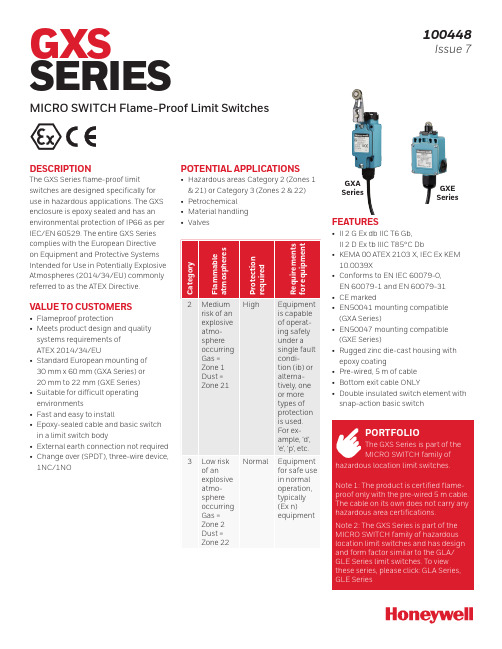
DESCRIPTIONThe GXS Series flame-proof limitswitches are designed specifically for use in hazardous applications. The GXS enclosure is epoxy sealed and has an environmental protection of IP66 as per IEC/EN 60529. The entire GXS Series complies with the European Directive on Equipment and Protective Systems Intended for Use in Potentially Explosive Atmospheres (2014/34/EU) commonly referred to as the ATEX Directive.VALUE TO CUSTOMERS• Flameproof protection• Meets product design and quality systems requirements of ATEX 2014/34/EU• Standard European mounting of 30 mm x 60 mm (GXA Series) or 20 mm to 22 mm (GXE Series)• Suitable for difficult operating environments• Fast and easy to install• Epoxy-sealed cable and basic switch in a limit switch body• External earth connection not required • Change over (SPDT), three-wire device, 1NC/1NOPOTENTIAL APPLICATIONS• Hazardous areas Category 2 (Zones 1 & 21) or Category 3 (Zones 2 & 22)• Petrochemical • Material handling• ValvesGXA SeriesGXE SeriesGXS SERIESMICRO SWITCH Flame-Proof Limit Switches100448Issue 7FEATURES• II 2 G Ex db IIC T6 Gb, II 2 D Ex tb IIIC T85°C Db• KEMA 00 ATEX 2103 X, IEC Ex KEM 10.0039X• Conforms to EN IEC 60079-0, EN 60079-1 and EN 60079-31• CE marked• EN50041 mounting compatible (GXA Series)• EN50047 mounting compatible (GXE Series)• Rugged zinc die-cast housing with epoxy coating• Pre-wired, 5 m of cable • Bottom exit cable ONLY• Double insulated switch element with snap-action basic switchPORTFOLIOThe GXS Series is part of the MICRO SWITCH family ofhazardous location limit switches.Note 1: The product is certified flame-proof only with the pre-wired 5 m cable. The cable on its own does not carry any hazardous area certifications.Note 2: The GXS Series is part of the MICRO SWITCH family of hazardous location limit switches and has design and form factor similar to the GLA/GLE Series limit switches. To view these series, please click: GLA Series, GLE SeriesEN IEC 60079-0, EN 60079-1, EN 60079-31 II 2 G Ex db IIC T6 Gb, II 2 D Ex tb IIIC T85°C Db KEMA 00 ATEX 2103 X; IEC Ex KEM10.0039X(X indicates special conditions for safe use, see certificates for details) AC15, DC131NC/1NO change over contacts Double insulated switch elementNo internal or external earth connection silverGXA or GXESwitch TypeASide Lever Roller MaterialGXA Series Hazardous Area Limit Switch GXE Series Hazardous Area Limit Switch#Cable Length1CircuitryActuatorTypeAHead Orientation3Figure 1. Product NomenclatureNote: GXA Side Rotary and GXE Plunger versions shown.Figure 2. GXA Series Dimensions mm [in]Ø19,1 mmFigure 3. GXA Series Side Rotary Adjustable Dimensions(refer to Figure 2 for additional measurements)Figure 4. GXA Series Pin Plunger Dimensions(refer to Figure 2 for additional measurements)Figure 5. GXA Series Roller Plunger Dimensions(refer to Figure 2 for additional measurements)Note: GXA Side Rotary and GXE Plunger versions shown.Figure 8. GXE Series Side Rotary Adjustable Dimensions mm [in] (refer to Figure 6 for additional measurements)Figure 9. GXE Series Roller PlungerDimensions mm [in](refer to Figure 6 for additionalmeasurements)Figure 10. GXE Series Roller LeverDimensions mm [in](refer to Figure 6 for additionalmeasurements)Figure 7. GXE Series Side RotaryDimensions mm [in](refer to Figure 6 for additionalmeasurements)Warranty/RemedyHoneywell warrants goods of itsmanufacture as being free of defective materials and faulty workmanship.Honeywell’s standard product warranty applies unless agreed to otherwise by Honeywell in writing; please refer to your order acknowledgement or consult your local sales office for specific warranty details. If warranted goods are returned to Honeywell during the period ofcoverage, Honeywell will repair or replace, at its option, without charge those items it finds defective. The foregoing isbuyer’s sole remedy and is in lieu of all other warranties, expressed or implied, including those of merchantability and fitness for a particular purpose. In no event shall Honeywell be liable for consequential, special, or indirect damages.While we provide application assistance personally, through our literature and the Honeywell web site, it is up to the customer to determine the suitability of the product in the application.Specifications may change without notice. The information we supply is believed to be accurate and reliable as of this printing. However, we assume no responsibility for its use.100448-7-EN | 7 | 11/22Sensing and Safety Technologies Honeywell830 East Arapaho Road Richardson, TX 75081FOR MORE INFORMATIONHoneywell Sensing and SafetyTechnologies services its customers through a worldwide network of sales offices and distributors. For application assistance, current specifications, pricing, or the nearest AuthorizedDistributor, visit /ast or call:USA/Canada +302 613 4491Latin America +1 305 805 8188Europe +44 1344 238258Japan +81 (0) 3-6730-7152Singapore +65 6355 2828Greater China+86 4006396841m WARNINGPERSONAL INJURYDO NOT USE these products as safety or emergency stop devices or in any other application where failure of the product could result in personal injury.Failure to comply with theseinstructions could result in death or serious injury.m WARNINGMISUSE OFDOCUMENTATION•The information presented in this product sheet is for reference only. Do not use this document as a product installation guide.•Complete installation, operation, and maintenance information is provided in the instructions supplied with each product.Failure to comply with theseinstructions could result in death or serious injury.。
一种蜂蜜升温箱[实用新型专利]
![一种蜂蜜升温箱[实用新型专利]](https://img.taocdn.com/s3/m/a8f2e1054afe04a1b171dea2.png)
专利名称:一种蜂蜜升温箱
专利类型:实用新型专利
发明人:彭巧玲
申请号:CN201720514035.6申请日:20170509
公开号:CN206909434U
公开日:
20180123
专利内容由知识产权出版社提供
摘要:本实用新型提供一种蜂蜜升温箱,包括箱体、控制器、加热装置、散热装置,所述控制器安装于所述箱体的内侧壁上,所述控制器分别与所述加热装置、散热装置相连接,所述散热装置包覆于所述加热装置的外表面上。
本实用新型采用上述技术方案,与现有技术相比,避免了箱底废弃物滋生巢虫的危害,克服了因外界气温变化给中蜂造成的危害,取蜜方便,提高了中蜂蜂蜜的质量和产量。
申请人:杭州寻野农业科技有限公司
地址:310000 浙江省杭州市余杭区中泰街道泰杭路10号308室
国籍:CN
更多信息请下载全文后查看。
Duke Thermaduke 电子食物加热器说明书

Illustrated Parts ListThis manual is Copyright © 2005 Duke Manufacturing Company. All rights reserved. Reproduction without written permission is prohibited. Duke is a registeredtrademark of the Duke Manufacturing Company.Duke Manufacturing Company2305 N. Broadway St. Louis, MO 63102Phone: 314-231-1130Toll Free: 1-800-735-3853Fax: THERMADUKE ELECTRIC FOOD WARMERMODEL E-2 DLPG E-2 DLSSE-3 DLPG E-3 DLSS E-4 DLPG E-4 DLSS E-5 DLPG E-5 DLSS E-6 DLPGE-6 DLSS E-2 CBSS EP-2 CBSS EP-2 CBPG E-3 CBSS EP-3 CBSS EP-3 CBPG E-4 CBSS EP-4 CBSS EP-4 CBPG E-5 CBSS EP-5 CBSS EP-5 CBPG E-6 CBSS EP-6 CBSS EP-6 CBPGIllustrated Parts List for Thermaduke Electric Food WarmerTHERMADUKE ELECTRIC FOOD WARMERITEM QTY. PART NUMBER DESCRIPTION1 1 251046 Louver2 1 216444 Unit Conditioner3 1 217498 Thermostat, Cold STD 74 1 402010 Thermaduke Base 2 Section 208VAC1 402212 Thermaduke Base 2 Section 236 Single Phase1 402013 Thermaduke Base2 Section 236 VAC3 Phase1 401439 Thermaduke Base 2Section 115VAC1 401440 Thermaduke Base 3 Section 115VAC1 402024 Thermaduke Base 3 Section 208VAC1 402026 Thermaduke Base 3 Section 236VAC Single Phase5 AR 154388Bibb Valve6 AR 214405Knob Guard7 AR 212190Knob8 AR 215556Pilot Light 208-240VAC MTRAR 215550Pilot Light Amber 125VACAR 215555Pilot Light Amber 208-240VACAR 212071Pilot Light Bulb 115VAC Red9 AR 230162Element Pan10 AR 230072Element Holder11 AR 154352 Element 120VAC 750WAR 154353 Element 208VAC 750WAR 154355 Element 240VAC, 750W12 AR 154048Drain Strainer13 1 400290 Dish Shelf1 400291 Dish Shelf2 Section1 400292 Dish Shelf3 Section1 400293 Dish Shelf 5 Section1 400294 Dish Shelf 6 Section14 AR 214508Adjustable Leg SS 1-5/8”x6” AdjustableIllustrated Parts List for Thermaduke Electric Food WarmerTHERMADUKE ELECTRIC FOOD WARMER15 1 212837 Ground LugITEM QTY. PART NUMBER DESCRIPTION16 AR 230363Drain Support17 AR 153471Hi-Limit Thermostatic Switch18 AR 212081Thermostat, Heat19 1 400011 Bottom Shelf 2 Section 24”1 400005 Bottom Shelf2 Section SS 24”1 400012 Bottom Shelf3 Section 24”1 400006 Bottom Shelf 3 Section SS 24”1 400013 Bottom Shelf 4 Section 24”1 400007 Bottom Shelf 4 Section SS 24”1 400014Bottom Shelf 5 Section 24”1 400008 Bottom Shelf 5 Section SS 24”1 400015 Bottom Shelf 6 Section 24”1 400009 Bottom Shelf 6 Section SS 24”20 1 212113Toggle Switch 115VAC Single Phase1 212100Toggle Switch 3 Pole 3 Phase21 1 2321065152 Switch Pan22 1 215351 Carving Board 45.875 x 10 x 1.11 215352 Carving Board 59.875 x 10 x 1.11 215353 Carving Board 73.875 x 10 x 1.11 215354 Carving Board 87.875 x 10 x 1.13 403395Carving Board Insert 10”23 2 400243Carving Board Bracket 24” Body24 1 400338Door Guide Inside1 400337Door Guide Outside25 2 401259 Door Panel Inside2 401263 Door Panel Inside2 401469 Door Panel Inside2 401251 Door Panel Outside2 401255 Door Panel Outside2 402471 Door Panel Outside26 2 214600Handle Recessed Pull1 215047Handle K-Line 12-1/4”Illustrated Parts List for Thermaduke Electric Food WarmerTHERMADUKE ELECTRIC FOOD WARMERITEM QTY. PART NUMBER DESCRIPTIONN ot Shown 1 400194 Door Assembly1 400191 Door 4 Section1 400196 Door 5 SectionN ot Shown 4 400208 Pan Leg 24”N ot Shown 1 212288Switch, Lighted Subway 120VACN ot Shown 1 212612Wiring Harness 2 Section 115VAC1 212613 Wiring Harness2 Section 208VAC1 212614Wiring Harness 3 Section 115VAC1 212615Wiring Harness 3 Section 208VAC1 212622 Wiring Harness3 Section 3 Phase1 212616Wiring Harness 4 Section 120VAC1 212617Wiring Harness 4 Section 208VAC1 212623Wiring Harness 4 Section 3 Phase1 212618Wiring Harness 5 Section 120VAC1 212619Wiring Harness 5 Section 208VAC1 212624Wiring Harness 5 Section 3 Phase1 212621Wiring Section 6 Section 208VAC1 212625Wiring Section 6 Section 3 PhaseAR 154242 Wiring Harness, Sealed Well, 115 VAC, 2 SectionAR 154424Wiring Harness Sealed WellIllustrated Parts List for Thermaduke Electric Food WarmerFigure: Thermaduke Electric Food WarmerTHERMADUKE ELECTRIC FOOD WARMERDuke Manufacturing Company2305 N. BroadwaySt. Louis, MO 63102Phone: 314-231-1130Toll Free: 1-800-735-3853Fax: 314-231-5074。
电热恒温培育箱操作方法及使用要点 培育箱如何操作
电热恒温培育箱操作方法及使用要点培育箱如何操作电热恒温培育箱是一种常用的试验设备,具有性能稳定、使用快捷、牢靠性高等优点,可供医疗卫生、医药工业、生物化学、工业生产及农业科学等科研部门作细菌培育、育电热恒温培育箱是一种常用的试验设备,具有性能稳定、使用快捷、牢靠性高等优点,可供医疗卫生、医药工业、生物化学、工业生产及农业科学等科研部门作细菌培育、育种、发酵及其他恒温试验用。
今日我们紧要来介绍一下电热恒温培育箱操作方法及使用要点,希望可以帮忙到大家。
一、电热恒温培育箱操作方法:1、接通电源,按下电源开关,此时电源指示灯亮。
2、操作人员需认真阅读使用说明,了解、谙习培育箱功能后,才能接通电源。
3、当培育箱显示温度达到设定温度时,加热停止、加热指示灯熄灭,在标准环境温度下通电90分钟后,温度可保持稳定,如箱内即时温度超过设定上限报警温度控温仪温度跟踪报警指示灯亮,同时自动切断加热器电源。
4、把温度掌控仪调到用户所需的设定温度值。
5、如打开玻璃门取样品时,加热器、循环风机会停止工作,当关上玻璃门后,加热器和风机才能正常运转,这样可避开培育物的污染及温度的过冲现象电热恒温培育箱使用要点:1、仪器不宜在高压、大电流、强磁场条件下使用,以免干扰温控仪及发生触电不安全。
2、电热恒温培育箱外壳必需有效接地,以保证使用安全。
3、本产品出厂前已经过严格调试,控温仪菜单设定数据,请勿任意修改。
4、请勿放置易燃易爆物品进行加温,严防发生不安全。
5、电镀零件和表面饰漆,应常常保持清洁,如长期不用,应在电镀件上涂中性油脂或凡士林,以防腐蚀,培育箱外面套好塑料薄膜防尘罩将培育箱放在干燥室内,以免控温仪受潮损坏。
6、请勿放置高酸高碱物品,防止箱体腐损。
—专业分析仪器服务平台,试验室仪器设备交易网,仪器行业专业网络宣扬媒体。
相关热词:等离子清洗机,反应釜,旋转蒸发仪,高精度温湿度计,露点仪,高效液相色谱仪价格,霉菌试验箱,跌落试验台,离子色谱仪价格,噪声计,高压灭菌器,集菌仪,接地电阻测试仪型号,柱温箱,旋涡混合仪,电热套,场强仪万能材料试验机价格,洗瓶机,匀浆机,耐候试验箱,熔融指数仪,透射电子显微镜。
FWE 组合伴侣 FWE 加热保温伴侣 产品说明书
OPERATING INSTRUCTIONSTM HEATED HOLDING COMPANION“HHC”SERIESHEATED HOLDINGCOMPANION CABINETHHC-CC-MWShown with Rational ®Rack (Not included.)CONGRATULATIONS......and thank you for purchasing an FWE COMBI-COMPANION or FWE HEATED HOLDING COMPANION heated holding cabinet.Y our unit has been designed and manufactured under rigid controls to assure you the most efficient service.It is a full time unit,and may be used continuously.Please take a moment to read through this booklet of important information pertaining to your cabinet.By following a routine ofproper use and care described on the following pages, your cabinet will last for many years.IMPORTANT:Y our Manufacturer Registration Card must be returned within 30 days after initial delivery to activate the warranty.HHC-CC HHC-CC-MWCAUTION:HOLDING FOOD AT TEMPERATURES OF LESS THAN 140°F MAY BE DANGEROUS.TEMPERATURES UNDER 140°F PROMOTE THE GROWTH OF HARMFUL BACTERIA AND TOXINS IN SOME FOODS.FOOD SENTRY SYSTEM ON/OFF Button TEMPERATURE OF CABINET SET DIAL FOR TEMPERATURE LOW TEMP ALARM RECALL TEMP SET POINT INDICATOR LIGHTS Low Temp Alarm -NOTE:THE FACTORY DEFAULT FOR THIS FEATURE IS IN THE “OFF”OR DISABLED MODE.Unit has a built in “Low Temp”alarm, allowing the operator to have an audible and a visual indicator that the heatedcabinet has dropped below the “Low Temperature”setpoint for more than two (2) minutes.1.)Adjust Set Point:Press and hold “Low Temp Alarm”key.While holding,rotate dial to desired set point between “OFF”and from 90°F (32°C) and190°F (88°C).Release button to accept adjustments.When the internalcabinet temperature falls below this “Set Point”for more than two (2)minutes, the audible and visual alarm will alert you to this condition.2.)Recall Set Point:Press “Low Temp Alarm”key to recall setting.The display reverts back to the normal display after three (3) seconds.3.)Acknowledge:Press any key to cancel beeping and flashing LED.The LED remains lit until the temperature rises above the alarm set point.4.)Disable:Follow the adjustment steps above.A rotation of the dial “down”below 90°F (32°C) turns the alarm feature off.Recall Temp Set Point -Unit may display either “Actual Internal Cabinet”actual temperature, or desired “Set Point”temperature.Actual:The factory default setting shows the actual internal cabinettemperature and acts as a digital thermometer.A momentary touch of the “Recall Temp Set Point”key will recall the original dial setting.The display will then automatically return to the actual internal temperature.Set Point:To have temperature read-outdisplay the “Set Point”temperature, press and hold the “Temp”key for five (5) seconds.The fourth (4th) digit onthe display will flash either “S”(Set), or “A”(Actual) to indicate which mode isactive.To switch back again, repeat this step holding the “Recall Temp Set”key for five (5) seconds.Low Temp AlarmIndicator Light -The “Low Temp Alarm”light will blink while setting the “Low Temp Set Point”.When the temperature falls below the “Low Temp”set point, the indicatorlight will blink until the alarm is cancelled/acknowledged.The light will remainilluminated until the interior cabinet temperature reaches above the“Low Temp Set Point”again.Q On/Off Switch - A.) T urns cabinet on and off.B.) °Celsius and °Fahrenheit Scale:Y ou may change the Digital thermometer scale to either °C or °F as follows:While unit is “Off”, press and hold the “ON/OFF”key for five (5) seconds.The display will then switch from “dgF”to “dgC”.Repeat to change scale again.Dial -Use dial to set the desired temperature.Dial rotates completely.Power Indicator Light -Indicates that the power is on.Cycling Indicator Light -When light is “ON”, this indicates that thecabinet is warming up to desired temperature.When heating elements are activated, light willcome “ON”until cabinet has reached desiredtemperature, and go “OFF”when unit has reached desired temperature.Temp Display -Digital temperature display:A.)°Celsius and °Fahrenheit Scale:Y ou may change the Digital thermometer scale to either °C or °F as follows:While unit is “Off”, press and hold the “ON/OFF”key for five (5) seconds.The display will then switch from “dgF”to “dgC”.Repeat to change scale again.B.)Unit may be set to show either actual internal temperature, or “Set PointTemperature”.(See “Recall Temp Set Point”)®Food Warming Equipment Company 7900 South Route 31 Crystal Lake, Illinois 60014Phone:815-459-7500Fax:815-459-7989***************UICK-S TART G U I D E 3INSTALLATION AND CARESERIAL AND MODEL NUMBERThese numbers are found on the nameplate (serial tag) affixed to the unit by the electrical cord.Please record them in this booklet,in the space provided on page 9.When ordering parts and/or service, you will need to provide this information.The voltage and amperage of the unit are also stamped on the serial tag. UNPACKINGAfter uncrating your cabinet, remove all tape and padding which held all doors, shelves, racks, cord, etc., in place during shipment. ELECTRICAL REQUIREMENTS AND GROUNDINGFWE standard models operate on 110/120 volt, 60 Hz, 1 ph, A.C. (unless ordered otherwise), and are equipped with a three prong grounding cord plug for your protection against possible shock hazards.Be sure to plug only into a properly grounded three prong wall receptacle.If you have any questions with regardto adequate wiring or grounding in your building, a qualified electrician should be contacted before using your cabinet.The amperage of your cabinet is stamped on the name plate attached to the unit.DO NOT,UNDER ANY CIRCUMSTANCES,CUT OR REMOVE THE GROUNDING PRONG FROM THE CORD PLUG.WARNING:ONL Y A QUALIFIED ELECTRICIAN SHOULD ATTEMPT TO REPAIR OR REPLACE ELECTRICAL COMPONENTS OR WIRING.BE SURE THAT MODEL IS UNPLUGGED FROM ELECTRICAL SOURCE BEFORE REMOVING CONTROL PANEL.CLEANINGKeep your cabinet clean by simply wiping the interior and exterior, as needed, with a damp cloth or sponge and a mild soapy solution.NEVER USE ABRASIVES,ACIDS,ORSTRONG CLEANERS.Do not flood or allow electrical parts to become wet.The interior tray slide assemblies and humidifier pansare removable for easy cleaning.A stainless steel cleaner/polish is recommended for the exterior to maintain a "like-new" appearance.DO NOT USE WAX OR STRONG CLEANERS ONDOOR GASKETS OR VINYL TRIM.FOOD SENTRY CONTROLSThe control panel, recessed at the top of the unit above the door, is equipped with an adjustable thermostat (to 190°F) for temperature selection, a digital thermometer to show the actual internal temperature of the cabinet, ON/OFF switch, a red power indicating light to tell you when the cabinet is on, and an indicating light which illuminates when the heating element is activated and cycling.Recall Temp Set Point -Unit may display either “Actual Internal Cabinet”actual temperature, or desired “Set Point”temperature.Low Temp Alarm -Unit has a built in “Low Temp”alarm, allowing the operator to have an audible and a visual indicator that the heated cabinet has dropped below the “Low Temperature”set point for more than two (2) minutes.NOTE:THE FACTORY DEFAULT FOR THIS FEATURE IS IN THE “OFF”OR DISABLED MODE.PREHEAT CABINET BEFORE LOADING HOT FOOD1) PLUG CABINET INTO A PROPERLY GROUNDED POWER RECEPTACLE.Press ON/OFF icon.The power indicating light will come on and remain on until ON/OFF icon is pressed again, or the unit is unplugged.2) SELECT A TEMPERATURE SETTING.For most foods, a holding temperature of 150°- 160°F shouldbe adequate.3) FOR BEST RESULTS,PRE-HEAT CABINETFOR AT LEAST 30 MINUTES,HEATING UPTHE INTERIOR STAINLESS STEEL WALLS.When the cycling light goes off, the cabinet “air”has reached the temperature which you selected in step 2. By pre-heating cabinet at least 30*minutes, even after the cycling light has gone off, you are heating up the stainless steel wall interior.This retains cabinet heatfor faster recovery times.By thoroughly pre-heating the unit before each use,you heat up the interior stainless steel and obtainthe best holding results from your cabinet.4) LOAD THE CABINET with your Combi or Steamer Mobile Plate Rack.After loading is completed, do not open doors again until you are ready to serve.DO NOT PUT COLD FOODSINTO A HOT CABINET!PUT HOT FOOD INTO A HOT CABINET5) TRANSPORTING HOT FOODS.Mobile cabinets are equipped with a positive transportation latch to assure safety during transportation.Before moving the cabinet, keep it plugged in and wait until the red cycling light goes off.This recovery takes only a short time, and allows the internal temperature to again reach the setting you have selected.As soon as the cycling light goes off, unplug the cabinet and wheel to serving area. Plug the cabinet into an electrical outlet at the serving location (if available), so that the thermostat willre-activate and automatically hold your pre-selected temperature.6) STATIONARY CABINETS WITH LEGS.NOTE: Adjustable legs mounted to cabinet may need height adjustment upon delivery prior to cabinet usage.Proper height of cabinet is critical to achieve proper docking of rack. Optimum space tolerance is necessary to allow for heat expansion, preventing scaring and scratches to cabinet or damage to rack.Adjustment to cabinet legs is accomplished easily with cabinet upright by turning the tapered floor tipof each leg clock-wise (to the left) to raise cabinet;counter-clockwise (to the right) to lower cabinet.SET-UP PRIOR TO OPERATION.TROUBLE-SHOOTING CHARTCheck this list first before you call for service...FWE PARTS DEPARTMENT: 815 459 7500REPLACEMENT PARTSPART NUMBER Knob for thermostatKNB H7 Push handle, aluminum bar, 12.5”HDL 12.5 AL Push handle, aluminum bar, 21.5”HDL 21.5 AL Spacers for push handlesSPCR125x.330 Bolts, hex head for handlesB1/4-20x32NZ Door Latch - Chrome MagneticLTH MAG Bumper insert, black vinylBMPR INSERT Extension Cord 10 ft.Plug:5-15PCRDSET10/115 Extension Cord 10 ft.Plug:5-20PCRDSET20/115 Casters:5'' rigidCSTR 5 R-2 Casters:5'' swivel with brakeCSTR 5 SB-2T ray slides, pair (TST models)SLD TS245 Tray slides, pair (UHST models)SLD UHS245Shelves:Sized by Model Number Consult Factory Other Replacement Parts are available.Your Model Number and Serial Number are required when requesting Parts or Service.These numbers are listed on your Serial Tag located by the power cord.TEMPNOTHOTENOUGH NO HEATAT ALL 1A] Opening door unnecessarily 1B] Thermostat set too low 1C] Cord plug pulled out from outlet 1D] Fuse blown - no power to outlet1E] Pre-Heat Cabinet 2A] Cabinet not plugged into outlet2B] Cabinet power “ OFF ”2C] Fuse Blown - no power to outlet 2D] Heating element needs replacing 2E] Control panel needs replacing 1A] Heat escapes from cabinet when door is opened too frequently.1B] Set thermostat at a higher temperature.1C] Replug cord into proper outlet.1D] Have a qualified electrician check power and fuse box.1E] Assure interior of cabinet heats up,not just cabinet air temperature.Allow at least 30 minute pre-heat.2A] Plug cabinet into properly grounded electrical outlet.2B] Press power icon on the control panel 2C] Have a qualified electrician check powerto fuse box.2D] Heating element will either functionor not function.Consult factory.2E] Consult factory.SERVICE RECORDModel Number ______________________Serial Number ______________________Date of Purchase ______________________Notes:___________________________________________________ ___________________________________________________ ___________________________________________________ ___________________________________________________ ___________________________________________________ ___________________________________________________ ___________________________________________________ ___________________________________________________ ___________________________________________________ ___________________________________________________ ___________________________________________________ ___________________________________________________ ___________________________________________________ ___________________________________________________ ___________________________________________________ ___________________________________________________ ___________________________________________________ ___________________________________________________ ___________________________________________________ ___________________________________________________ ___________________________________________________ ___________________________________________________ ___________________________________________________ ___________________________________________________ ___________________________________________________ ___________________________________________________ ___________________________________________________WIRING DIAGRAMLIMITED TWO YEAR WARRANTYFWE / Food Warming Equipment Company,Inc.(Seller) warrants to the original purchaser, subject to the exceptions and conditions below, that FWE manufactured equipment shall be free from defects in material or factory workmanship, under ordinary use for the purpose for which it is designed.The effective warranty period is as follows:PARTS:Seller will furnish without charge to the original purchaser, FOB Sellers’factory, replacement parts for repairs to all new standard catalog products and factory custom / modified units, which in Seller’s sole judgement, prove defective in materials or workmanship under normal and proper use with the reserved right to request the return of any part claimed to be defective, prior to issuing replacement part or authorizing warranty service, for a period of two (2) years from date of original shipment from Seller’s plant, except for equipment used in a Correctional Environment / Facilities, which is warranted for a period of one (1) year from date of original shipment from Seller’s plant.LABOR:Seller’s labor warranty shall be performed by a Seller-approved Service Agency who must contact Seller to obtain a Warranty Service Authorization (WSA) number prior to performing any repairs.If service is required during overtime periods, the difference between overtime and standard labor rates shall be paid by the purchaser.Seller does not assume any responsibility for any charges not expressly authorized, incidental to the repair or replacement of equipment covered by this warranty, nor charges exceeding, in Sellers sole judgement, normal and customary amounts.Only approved travel charges will be allowed.Seller’s labor warranty shall be from the date of original shipment date from Seller’s plant for a period of one (1) year, except for equipment used in a Correctional Environment / Facilities which is warranted for a period of six (6) months.This warranty is for normal usage and does not apply to any product or parts thereof that have been misused, altered, or where Seller’s operating instructions or specific voltage is not observed;nor shall this warranty apply to defective products or parts resulting from accident following date of original shipment, nor extend to or cover removal, installation, reinstallation or calibration, or service calls or cost of repairs undertaken by a customer.This warranty is also subject to the following:1.] Customer returning the warranty registration card, accompanying Sellers originalshipment, to Seller within thirty (30) days of receipt;2.] Giving immediate notice of any allegedly defective part or product to Seller;and3.] Customer, at Sellers request, returning said defective parts or product to Seller.This is the sole warranty applicable to the merchandise.It is expressly understood that Seller’s liability hereunder is limited to the repair or replacement, at Seller’s option, of products or parts, defective materials or workmanship as provided above.Seller’s judgement as to the cause and nature of any defect will be final.Seller shall in no case be responsible for special or con-sequential damages or any other obligation or liability with respect to products sold by Seller. This warranty, as stated above, applies to equipment installed in the Continental United States. FWE equipment installed outside the Continental United States shall carry parts coverage only.All labor costs are approved on a discretionary basis, based on like repairs in the Continental U.S.This warranty shall stand in whole or in part as allowed by law.Any exclusion of a part of this warranty, as may be allowed by law, shall not void balance of warranty.This is a limited warranty pursuant to the Consumer Product Warranties Act, 15 U.S.Code.section 2303.©2003 Food Warming Equipment Co., Inc.11WE OFFER SALES AND SERVICE WORLDWIDE Food Warming Equipment Company, Inc.P .O.Box 1001Crystal Lake, IL 60039-1001Manufacturing Facilities:7900 S.Route 31Crystal Lake, IL 60014OpMan_HHC_FoodSentry ©2008 Food Warming Equipment Co., Inc.Printed in USA FWE Parts Department:815 459 7500FAX:815 459 7989The best designed . . .The best built . . . The best performing units on the market!◊◊◊◊◊◊◊◊◊Retherm CabinetsSelf-Propelled TransportsHeated Banquet CabinetsUniversal Bulk FoodCabinetsUtility CartsRefrigerators,Freezers andConvertiblesPrisoner & Correctional TrayDeliveryHospital Tray Delivery CartsPortable Bars and Back-upsErrors subject to correction.All specificationssubject to change without notice.©08 Food Warming Equipment Company.Inc.。
恒温 极氪001 温控策略
恒温极氪001 温控策略恒温是一种维持恒定温度的控制策略,可以在各种环境中实现对温度的精确控制。
在极氪001温控策略中,恒温被用于保持系统的稳定性和性能。
恒温技术可以广泛应用于实验室、医疗、工业生产等领域。
它可以提供一个恒定不变的温度环境,以满足特定的需求。
在极氪001的温控策略中,恒温技术被用于确保设备的运行温度恒定,并防止过热或过冷。
为了实现恒温,极氪001温控策略通常包括以下步骤:1. 温度传感器检测:系统会安装一个高精度的温度传感器来实时检测当前环境的温度。
传感器将温度数据传输给控制系统,以便进行后续的处理和调节。
2. 温度控制算法:极氪001采用先进的温度控制算法,根据温度传感器提供的数据来判断当前温度与目标温度之间的差异。
根据差异,控制系统将做出相应的调节措施。
3. 温度调节设备:温度调节设备,如加热器、制冷装置等,将根据温度控制算法的指示进行操作。
如果当前温度低于目标温度,加热器将被启动以提高温度;如果当前温度高于目标温度,制冷装置将被启动以降低温度。
通过不断地调整温度调节设备的工作状态,系统可以保持恒定的温度。
4. 反馈控制:系统会不断地监测温度传感器的反馈,以确保温度调节的准确性和稳定性。
如果温度偏离了设定的范围,系统将进行纠正,以使温度恢复到设定值。
恒温是极氪001温控策略中的重要组成部分,它可以确保设备的正常运行和性能不受温度变化的影响。
通过精确地控制温度,可以提高生产效率、实验结果的准确性,并保护设备免受过热或过冷的损害。
极氪001温控策略的应用具有重要的实际意义,对各行各业都有着广泛的应用潜力。
蜂群春季的外加温
蜂群春季的外加温张保定【期刊名称】《蜜蜂杂志》【年(卷),期】2014(034)004【总页数】1页(P25)【作者】张保定【作者单位】【正文语种】中文早春给蜂群外加温,一般不提倡,但任何事情都没有绝对的。
我从20世纪70年代初就给蜂群外加温,认为加温比不加温繁殖快,而且快得多。
我的办法如下:(1)买一种“烘鞋器”(淘宝网上能买到,十多元1个),总功率13W,有2个烘鞋片。
为了把2个烘鞋片放在2个蜂箱内,可延长一个烘鞋片的导线;为了调节烘鞋片温度,可加电热毯调温开关(图1)。
(2)用单人电热毯,铺在蜂箱下,电热毯下再铺保温物,1个电热毯上放置3个标准蜂箱,蜂箱周围再用保温物包好,切记电热毯只能用低温不能用高温。
图1 烘鞋器的改装以上2种任选一种,其中第一种为最为简单,而且还省电,晚上通电,白天通不通电依白天蜂飞出不冻僵为准,箱内发热器上不盖保温物(防火)。
多年来,经过反复试验,总结以下几点:(1)加温时间:春季第一代新蜂出房后开始加温。
西安地区一般在2月底3月初,到3月底左右停止加温。
(2)发热器的功率:发热器实际功率每箱不超过10W,6~8W最理想、注意“伤热”,这一点最重要。
(3)春季气候多变,须在外加温基础上,做好箱外保温,注意调节巢门。
(4)由于外加温,箱内温度适宜,减少的保温蜂体力转入育儿,蜂群发展得很快。
要及时补充糖(蜜)脾,3月初花粉少时加粉脾,适时加空脾,做到蜂脾相称,不一定要蜂多于脾,早春2框蜂到“春分”都能上继箱。
(5)注意用电安全和防火。
(6)勤检查箱内外,温度计放在覆布上保温物下,温度不能超过36℃,有条件可购1个数字温度计,把探针插入脾之间,数字温度计放在显眼方便处。
数字温度计40元左右1只。
(7)不论是单王群、双王群或多王群,每箱只放1个发热器。
(8)初学者先试验1~2群,试验温度宁低勿高,待有经验后再推广。
(9)用电量和效益:加温1个月按600小时,每个发热器按7W计算,1个月用电量为4.2kW·h,折合电费2.5元。
新一代蜂群恒温加热器
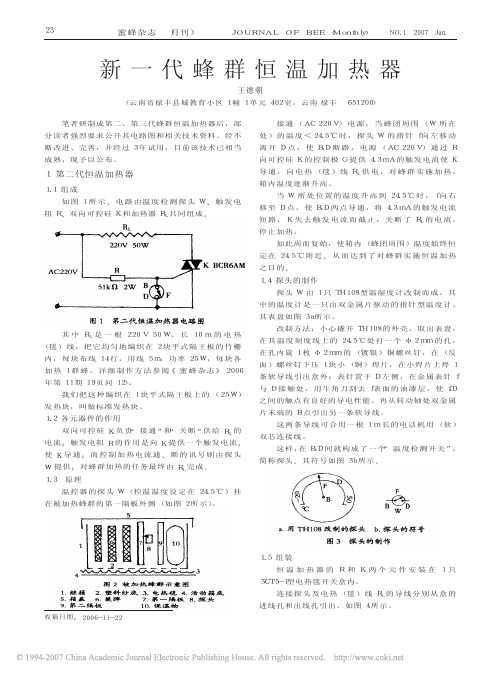
2007年第 1 期
蜜蜂杂志 (月刊)
J OURNAL OF BEE ( Monthly)
24
AC220V
R K
F
BD
R1 ZD RL
T1 T2 G
W
a. 各元件连接图
b. 可控硅 BCR 6AM 引脚 ( 正面向上)
图 4 恒温加热器组装图
步 骤 : 拆 开 3CTK5- 1 开 关 外 壳 , 拆 去 盒 盖 上 的 开关手柄、弹簧、触片等物, 留下空盒待用。取出盒 内的线路板 α ( 如图 4a 虚线框内所示) , 从板 α 上 拆除换挡二极管, 保留 ( 氖) 指示灯 ZD 及串在氖灯 上的电阻 R1。将所有元器件焊接在板 α 上。其中电 阻 R 及双向可控硅 K 分别焊在 α 板的正、反面上, 并将该二元件随板 α 装入空盒内; 探头 W 及电热 ( 毯) 线 RL 分别用双芯导线引出盒外。组装工作即告 结束。
2) 各群的加热功率必须严格保持一致, 即 25 W。 3) 由于恒温加热器要不间断地 连 续 工 作 45~60 天, 故对各元器件, 特别是双向可控硅的要求很高, 必须选用正品 ( 或进口) 的元件。 4) 被加热蜂群所消耗的功率之和, 不得大于温 控器的输出功率。 5) 从事对蜂群实施恒温加热的蜂场, 在电路总 闸处必须安装漏电保护器。一旦发生触电事故, 保护 器会自动跳闸切断电源, 从而提高安全性能。 6) 其他未尽事宜, 请参阅《 蜜蜂杂志》2005 年 第 2 期第 5 页 、 第 8 期 第 19 页 和 2006 年 第 11 期 第 18 页的相关文章。
过些时候, 发热块间的温度逐渐降低, 当温度低 于 24.5 ℃时 , ZD 再 次 被 点 亮 , 电 路 亦 再 次 被 接 通 , RL 恢复加热。
电动吸蜂器的制作方法
电动吸蜂器的制作方法概述电动吸蜂器是一种用于捕捉和收集蜜蜂的设备。
它利用电动机驱动风扇产生负压,从而将蜜蜂吸入容器中。
本文将详细介绍制作电动吸蜂器的方法。
材料准备在制作电动吸蜂器之前,您需要准备以下材料: - 一个透明的塑料容器,用于收集被吸入的蜜蜂。
- 一个小型电动机和驱动装置,用于产生负压。
- 一根柔软的管道,连接电动机和容器。
- 一个开关,用于控制电动机的启停。
- 一些导线和插头,用于连接电路。
- 一块塑料或木板,用于固定和支撑设备。
制作步骤下面是制作电动吸蜂器的详细步骤:1. 设计并准备外壳您需要设计并准备一个外壳来容纳所有的部件。
您可以使用塑料或木板来制作外壳。
确保外壳足够大以容纳所有部件,并留有足够的空间进行连接和操作。
2. 安装电动机和驱动装置将电动机安装在外壳内的合适位置上,并使用螺丝固定。
确保电动机的风扇部分能够顺利转动,并与后面的容器相连。
3. 连接管道使用柔软的管道将电动机和容器连接起来。
确保管道长度适中,不会限制负压的产生。
您可以使用胶带或其他固定物品将管道固定在外壳上。
4. 安装开关将开关安装在外壳上,用于控制电动机的启停。
确保开关位置方便操作,并与电路连接良好。
5. 连接电路使用导线和插头将电路连接起来。
确保所有连接牢固可靠,并遵循正确的电路布线原则。
如果您不熟悉电路连接,请寻求专业人士的帮助。
6. 测试和调试完成组装后,进行测试和调试。
确保电动吸蜂器能够正常工作并产生足够的负压吸入蜜蜂。
如有必要,对设备进行微调和调试,以达到最佳效果。
注意事项在制作电动吸蜂器时,有几个注意事项需要牢记:1.安全第一:在操作电动机和电路时,请确保安全。
避免触摸裸露的导线和部件,以免触电。
2.使用透明容器:使用透明的容器可以方便您观察被吸入的蜜蜂数量和情况。
3.调整负压:根据实际需要,您可能需要调整电动吸蜂器产生的负压。
确保负压足够强大,但不会对蜜蜂造成伤害。
结论制作电动吸蜂器可以帮助您捕捉和收集蜜蜂。
GRILL 微波炉 说明书
ࠠᓃ
電源線中導線按照以下方式標色: 綠黃色 : 地線
藍 色 : 中線
褐 色 : 火線
本微波爐電源線中導線的色標可能與閣下所用的插頭(或插座)上的色標不相同、屆時請按以下規則操作:
綠黃色的導線必須與以下幾種插頭(插座)之一相接:標有E字母、帶有( )符號、色標為綠色或黃綠色。
īġ ౘ፡ႛᖦȃគݎȃछࠒҞȃዥޔȃ ॷဗЅច้ਢȃᘖڏҪኵЌȃᡱౘ፡ё ዥਢϱഋЫᇑྖюȄ
īġ ҢཌݰᝥᛖҝԽ߆ਢȃ҆ٺҢཌݰᝥ ᛖҝԽ߆டҢೡȄ
īġ ᠙ڗᛖҝԽ߆ᖐϐᄚڗIJĮijऌਢȃᔖୄ Х៉ౘ፡ȃоջႆЬȄġ
īġ ᙽ౾ᔉܻࠢॵڋཌݰᝥౘ፡ৠᏢϛȃ ωЖёዥϞȄġ҆ौਢȃ֯Ϻᡁܝኵԩȃ ޢՍёዥՍᎌ࿋࣏࡙ྣޟջᐻ༌Ȅ
īġ ޢёዥᔉڋѸ౭ਢȃ҆තўఋᇐڷ ѸቝȄġёዥࡣȃৈΰѸቝȃшӋϺȃ ႀՍᎌ࿋ྣ࡙ࡣȃϗᗽᔉॵڋҢȄ
īġ ౘ፡ԤᓥਟࡣࠢॵޟȃϷᘞϸȃ ᡱᇑྖюȃᗗջح༌Ȅ
īġ ёዥਟਢȃҢۻৠᏢȃо٩ ਟᘰюȄ
ʔ̙
īġ ౘ፡ܖёዥள෦ೖȄȞषȶᛖນȷȃ џཬᚽཌݰᝥȄȟ
藍色的導線必須與標有N字母或藍色的插頭(或插座)相接。
褐色的導線必須與標有L字母或褐色的插頭(或插座)相接。
R-667R(S) [02 CH].indd 3
C–3
12/23/09 10:17:08 AM
ЗΤ၈
1. 開門掣 2. 照明燈 3. 門鉸 4. 門鎖 5. 裝有透明窗的爐門 6. 爐門密封襯墊和襯墊表層 7. 燒烤發熱器 8. 聯接器 9. 波導管罩
- 1、下载文档前请自行甄别文档内容的完整性,平台不提供额外的编辑、内容补充、找答案等附加服务。
- 2、"仅部分预览"的文档,不可在线预览部分如存在完整性等问题,可反馈申请退款(可完整预览的文档不适用该条件!)。
- 3、如文档侵犯您的权益,请联系客服反馈,我们会尽快为您处理(人工客服工作时间:9:00-18:30)。
5 注意事项
1) 取样群和跟随群的群势应大致相同, 各蜂群 的保温情形、巢门大小、受光照射、受风吹的情形也 应尽可能一致。
图 4b 为 双 向 可 控 硅 BCR6AM( 正 面 朝 上 ) 的 引 脚排列图, 接线时切勿搞错。 1.6 调试
将 电 热 ( 毯 ) 线 RL 编 织 在 2 块 平 式 隔 王 板 上 , 构成 2 个标准发热块, 并将它们叠放在一起, 盖上保 温物; 把探头 W 塞入二标准发热块之间, 接通电源。 当外界气温低于 24.5 ℃时, 指示灯亮, 说明 RL 已通 电加热, 发热块之间的温度逐渐升高; 当温度达 24.5 ℃时, 指示灯 ZD 熄灭, 表明: 电路被切断, RL 停止加热。
当 W 所 处 位 置 的 温 度 升 高 到 24.5 ℃时 , f 向 右 移至 D 点, 使 B,D 两点导通, 将 4.3 mA 的 触 发 电 流 短 路 , K 失 去 触 发 电 流 而 截 止 , 关 断 了 RL 的 电 流 , 停止加热。
如此周而复始, 使箱内 ( 蜂团周围) 温度始终恒 定 在 24.5 ℃附 近 , 从 而 达 到 了 对 蜂 群 实 施 恒 温 加 热 之目的。
将 10 条电热 ( 毯) 线分别编织在 20 块平式隔王 板上, 构成 20 个 标 准 发 热 块 , 每 个 发 热 块 加 热 1 群 蜂。
按图 5b 所示, 把 10 条电 热 线 RL1~RL10 并 联 起
25
蜜蜂杂志 (月刊)
J OURNAL OF BEE ( Monthly)
NO.1 2007 Jan.
来接在 CT 上, 插入 CZ 内。 接通 ( AC 220 V) 电源即可。
4 管理
1) 开 始 加 热 的 头 3 天 , 每 天 分 别 于 早 上 8:00, 下 午 3:00 用 酒 精 温 度 计 ( 从 巢 门 插 入 ) 各 测 一 次 巢 温, 各群巢温的差异应≤±2 ℃, 若超过该范围, 则 做相应调整: 温度过高的群应开大巢门, 减少保温 物, 加强通风, 减少光照。调整正常后, 每 3 天测温 1 次。
①所需功率: 每个被加热群消耗 25 W 功 率 , 则 22 群所需总功率为 550 W< 2.5 kW ( 从 DZ 输出的功 率) 。可行。
② 电 热 ( 毯 ) 线 条 数 n: 每 2 群 需 ( 220 V 50 W) 电热 ( 毯) 线 1 条, 则 22 群蜂需 11 条, 除去恒 温控制器自带的 1 条 ( RL) 外, 还需要电热 ( 毯) 线 条数 n=10。 2) 实施
1 第二代恒温加热器
1.1 组成 如 图 1 所 示 , 电 路 由 温 度 检 测 探 头 W、 触 发 电
阻 R、双向可控硅 K 和加热器 RL 共同组成。 RL
220V 50W
AC220V
R
51kΩ 2W B DF
K BCR6AM
图 1 第二代恒温加热器电路图 其 中 RL 是 一 根 220 V 50 W、 长 10 m 的 电 热 ( 毯) 线, 把它均匀地编织在 2 块平式隔王板的竹栅 内, 每块布线 14 行, 用线 5 m, 功 率 25 W, 每 块 各 加 热 1 群 蜂 。 详 细 制 作 方 法 参 阅《 蜜 蜂 杂 志 》2006 年第 11 期 19 页问 12) 。 我们把这种编织在 1 块平式隔王板上的 ( 25 W) 发热块, 叫做标准发热块。 1.2 各元器件的作用 双向可控硅 K 负责“ 接通”和“ 关断”供 给 RL 的 电流; 触发电阻 R 的作用是向 K 提供一个触发电流, 使 K 导通; 而控制加热电流通、断的讯号则由探头 W 提供; 对蜂群加热的任务最终由 RL 完成。 1.3 原理 温 控 器 的 探 头 W ( 控 温 温 度 设 定 在 24.5 ℃) 挂 在被加热蜂群的第一隔板外侧 ( 如图 2 所示) 。
5. 箱盖 6. 巢脾
7. 第一隔板 8. 探头
9. 第二隔板
10. 保温物
收稿日期: 2006- 11- 22
a. 用 TH108 改制的探头 b. 探头的符号 图 3 探头的制作
1.5 组装 恒温加热器的 R 和 K 两个元件安装在 1 只
3CT5- 1型电热毯开关盒内。 连 接 探 头 及 电 热 ( 毯 ) 线 RL 的 导 线 分 别 从 盒 的
BX1
BX2 5A
5A R 51K
CZ CT
2W
AC 220V
T2
K
T1 BCR 25AM B
DF
R L1 R L2
R Ln
50W 50W
50W
W a. R L 加热两个取样群
图5
b. R L1 ̄R Ln 用 于 加 热 2n 个 跟 随 群 第三代恒温加热器
从 CZ 可输出 2.5 kW 供给其余的 n 条 ( 220 V 50 W) 电热 ( 毯) 线 ( LR1~LRn) , 对另外的 2n 个 ( 标 准箱) 群进行加热。我们把这 2n 个蜂群叫做跟随群, 即取样群被通电加热, 跟随群亦被加热; 取样群停止 加热, 跟随群也停止加热。
这两条导线可合用一根 1 m 长的电话机用 ( 软) 双芯连接线。
这样, 在 B,D 间就 构 成 了 一 个“ 温 度 检 测 开 关 ”, 简称探头。其符号如图 3b 所示。
- 20
FD
B ℃
50
F BD
W
1
6
7
9 10
8
2 3
4
图 2 被加热蜂群示意图
1. 继箱 2. 塑料纱底 3. 电热毯 4. 活动箱底
将待加热的蜂群提入箱内, 巢脾按从左到右的秩 序排列好; 插下第一块隔板, 在该隔板中部钉 1 枚小 钉子, 把探头 W 挂在钉子上。此群为取样群。在 W 外侧插第二块隔板, 在该板外加保温物。
另外一群为非取样群, 仅用 1 块隔板。两群并列。 接通电源即可实现对蜂群实施恒温加热 ( 参阅图 2) 。
1 直式隧道巢门可防治盗蜂
在外界蜜源较少或晚秋等盗蜂活动猖狂的季节, 使用直隧道巢门可有效预防和制止盗蜂。具体做法 是: 首先准备好 2 根圆木棍, 一根粗一根细, 细木棍 直径在 1 cm 左右, 粗木棍直径在 2 cm 左右, 木棍长 15 cm 左右; 和好一部分稀泥, 泥不要太稀, 以能捏 成团为度; 把小木棍一头伸向巢门口, 在巢门口小木 棍 周 围 糊 上 泥 , 要 糊 严 巢 门 , 把 小 木 棍 糊 去 3 cm 长 即可; 糊好泥后, 转动小木棍, 一边转一边抽出小木棍。
以每条电热 ( 毯) 线 50 W, 每群蜂消耗 25 W 功 率 计 算 , 2.5 kW 的 输 出 功 率 可 带 动 电 热 ( 毯 ) 线 的 条 数 n=50; 每 条 电 热 ( 毯 ) 线 可 加 热 2 群 蜂 , 则 可 对 2n=100 群蜂进行加热。
3 应用举例
某 蜂 场 计 划 用 第 三 代 恒 温 加 热 器 对 该 场 的 22 群 蜂实施加热 ( 参阅图 5) , 应先论证其可行性, 而后 组织实施。 1) 计算
进线孔和出线孔引出。如图 4 所示。
2007年第 1 期
蜜蜂杂志 (月刊)
J OURNAL OF BEE ( Monthly)
24
AC220V
R K
F
BD
R1 ZD RL
T1 T2 G
W
a. 各元件连接图
b. 可控硅 BCR 6AM 引脚 ( 正面向上)
图 4 恒温加热器组装图
步 骤 : 拆 开 3CTK5- 1 开 关 外 壳 , 拆 去 盒 盖 上 的 开关手柄、弹簧、触片等物, 留下空盒待用。取出盒 内的线路板 α ( 如图 4a 虚线框内所示) , 从板 α 上 拆除换挡二极管, 保留 ( 氖) 指示灯 ZD 及串在氖灯 上的电阻 R1。将所有元器件焊接在板 α 上。其中电 阻 R 及双向可控硅 K 分别焊在 α 板的正、反面上, 并将该二元件随板 α 装入空盒内; 探头 W 及电热 ( 毯) 线 RL 分别用双芯导线引出盒外。组装工作即告 结束。
1.4 探头的制作 探头 W 由 1 只 TH108 型温湿度计改 制 而 成 , 其
中的温度计是一只由双金属片驱动的指针型温度计, 其表盘如图 3a 所示。
改制方法: 小心撬开 TH108 的外壳, 取出表盘, 在 其 温 度 刻 度 线 上 的 24.5 ℃处 打 一 个 φ2 mm 的 孔 , 在孔内旋 1 枚 φ2 mm 的 ( 镀银) 铜螺丝钉, 在 ( 反 面) 螺丝钉下压 1 块小 ( 铜) 焊片, 在小焊片上焊 1 条软导线引出盒外; 表针置于 D 左侧, 在金属表针 f 与 D 接 触 处 , 用 牛 角 刀 刮 去 f 表 面 的 油 漆 层 , 使 f,D 之间的触点有良好的导电性能。再从转动轴处双金属 片末端的 B 点引出另一条软导线。
2) 各群的加热功率必须严格保持一致, 即 25 W。 3) 由于恒温加热器要不间断地 连 续 工 作 45~60 天, 故对各元器件, 特别是双向可控硅的要求很高, 必须选用正品 ( 或进口) 的元件。 4) 被加热蜂群所消耗的功率之和, 不得大于温 控器的输出功率。 5) 从事对蜂群实施恒温加热的蜂场, 在电路总 闸处必须安装漏电保护器。一旦发生触电事故, 保护 器会自动跳闸切断电源, 从而提高安全性能。 6) 其他未尽事宜, 请参阅《 蜜蜂杂志》2005 年 第 2 期第 5 页 、 第 8 期 第 19 页 和 2006 年 第 11 期 第 18 页的相关文章。
!!!!!!!!!!!!!!!!!!!!!!!!!!!!!!!!!!!!!!!!!!!!!!!!