WiFi智能插座中英文说明书
智能Wi-Fi插座HS100与HS110用户手册说明书
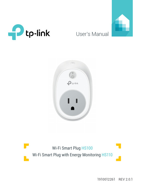
User’s Manual1910012261 REV 2.0.1Wi-Fi Smart Plug HS100Wi-Fi Smart Plug with Energy MonitoringHS110Copyright & TrademarksSpecifications are subject to change without notice. TP-Link is a registered trademark of TP-Link Technologies Co., Ltd. Other brands and product names are trademarks or registered trademarks of their respective holders.No part of the specifications may be reproduced in any form or by any means or used to make any derivative such as translation, transformation, or adaptation without permission from TP-Link Technologies Co., Ltd.© 2017 TP-Link. All rights reserved.CONTENTS4 Chapter 1. Introduction4 1.1 Product Overview4 1.2 Main Features5 1.3 Panel Layout7 Chapter 2. Quick Start8 Troubleshooting8 Frequently Asked Questions8 SupportChapter 1. Introduction1.1 Product OverviewWhat This Product DoesThe Wi-Fi Smart Plugs make it easy to control your lights or household electronic devices anywhere in the world with the TP-Link Kasa app on your smartphones or tablets.Schedule and Away ModeWith the Kasa’s Schedule and Away Mode, you can automate your lights or plugged-in appliances to turn on and off according to specific schedules, to simulate occupancy when you’re away from home. In addition, the countdown timer enhances safety by automatically switching off the running household appliances after a preset time.Compatible with Amazon EchoYou can pair the Smart Plugs with Amazon Echo for voice control. Compatible with Android, iOSThe free Kasa app lets you run them from any Android (5.0 and higher) or iOS (iOS 8 and higher) smartphone.Energy Conservation (for HS110 only)You can efficiently conserve energy and save money while using the Smart Plugs to control your space heaters and fans. The Smart Plug tracks your device’s power consumption in real-time, and has weekly and monthly summaries.1.2 Main Features•Control devices connected to the Smart Plug wherever you have Internet using the free Kasa app on yoursmartphone.•Schedule the Smart Plug to automatically power electronics on and off as needed, like setting lights to come on at dusk or turn off at sunrise.•Analyze your plugged-in device’s real-time and historical power* Image may differ from actual product due to different regional power specifications. Here we use the U.S. version as an example.Sta-tus Description(Settings /Press this button for 5 seconds or until the Wi-Fi LED blinks amber and green to initiate the app-config process.Press and hold for 10 seconds or until the Wi-Fi LED blinks amber rapidly to factory reset.Chapter 2. Quick Start1. Download Kasa for Mobile from the App Store or Google Play.ORscan QRcode2. Connect your mobile device to a 2.4GHz Wi-Fi network. Note: The Smart Plug only supports 2.4GHz networks.3. Launch Kasa and follow the app instructions to connect theSmart Plug to your network.TroubleshootingFrequently Asked Questions1. What devices can I control with the Smart Plug?You can control lights, electronics and small appliances such ashumidifiers, air purifiers, portable heaters and fans.2. What should I do when I can’t control the connected device?• Check that the connected device is switched to ON.• Make sure your mobile device and the Smart Plug are on the same Wi-Fi network.• Enable Remote Control to control the connected device from outside your home.3. What should I do when the Wi-Fi LED is lit red?A red LED light indicates no network connection.• Check your network connectivity.• Relocate the Smart Plug. Avoid placing the Smart Plug near potential sources of radio signal interference.• Repeat the app configuring process.• Factory reset the Smart Plug and try to add it again.4. How do I pair the Smart Plug with Amazon Echo?Visit /en/faq-944.html or within the Kasa Help section for pairing instructions.Support• Specifications can be found on the product page at • Our Technical Support and troubleshooting information can be found at /support.FCC StatementThis equipment has been tested and found to comply with the limits for a Class B digital device, pursuant to part 15 of the FCC Rules. These limits are designed to provide reasonable protection against harmful interference in a residential installation. This equipment generates, uses and can radiate radio frequency energy and, if not installed and used in accordance with the instructions, may cause harmful interference to radio communications. However, there is no guarantee that interference will not occur in a particular installation. If this equipment does cause harmful interference to radio or television reception, which can be determined by turning the equipment off and on, the user is encouraged to try to correct the interference by one or more of the following measures:• Reorient or relocate the receiving antenna.• Increase the separation between the equipment and receiver.• Connect the equipment into an outlet on a circuit different from that to which the receiver is connected.• Consult the dealer or an experienced radio / TV technician for help.This device complies with part 15 of the FCC Rules. Operation is subject to the following two conditions:1) This device may not cause harmful interference.2) This device must accept any interference received, including interference that may causeundesired operation.Any changes or modifications not expressly approved by the party responsible for compliance could void the user’s authority to operate the equipment.Note: The manufacturer is not responsible for any radio or TV interference caused by unauthorized modifications to this equipment. Such modifications could void the user’s authority to operate the equipment.FCC RF Radiation Exposure StatementThis equipment complies with FCC RF radiation exposure limits set forth for an uncontrolled environment. This device and its antenna must not be co-located or operating in conjunction with any other antenna or transmitter.“To comply with FCC RF exposure compliance requirements, this grant is applicable to only Mobile Configurations. The antennas used for this transmitter must be installed to provide a separation distance of at least 20 cm from all persons and must not be co-located or operating in conjunction with any other antenna or transmitter.”CE Mark WarningThis is a class B product. In a domestic environment, this product may cause radio interference, in which case the user may be required to take adequate measures.OPERATING FREQUENCY(the maximum transmitted power)2412MHz—2472MHz(20dBm)No restrictions exist in the use of radio frequencies or frequency bands in all EU member states and EFTA countries.EU declaration of conformityTP-Link hereby declares that the device is in compliance with the essential requirements and other relevant provisions of directives 2014/53/EU, 2009/125/EC and 2011/65/EU.The original EU declaration of conformity may be found at /en/ce.RF Exposure InformationThis device meets the EU requirements (2014/53/EU Article 3.1a) on the limitation of exposure of the general public to electromagnetic fields by way of health protection.The device complies with RF specifications when the device used at 20 cm from your body. Canadian Compliance StatementThis device complies with Industry Canada license-exempt RSSs. Operation is subject to the following two conditions:1) This device may not cause interference, and2) This device must accept any interference, including interference that may cause undesiredoperation of the device.Le présent appareil est conforme aux CNR d’Industrie Canada applicables aux appareils radio exempts de licence. L’exploitation est autorisée aux deux conditions suivantes :1) l’appareil ne doit pas produire de brouillage;2) l’utilisateur de l’appareil doit accepter tout brouillage radioélectrique subi, meme si lebrouillage est susceptible d’en compromettre le fonctionnement.Radiation Exposure StatementThis equipment complies with IC radiation exposure limits set forth for an uncontrolled environment. This equipment should be installed and operated with minimum distance 20cm between the radiator and your body.Déclaration d’exposition aux radiationsCet équipement est conforme aux limites d’exposition aux rayonnements IC établies pour un environnement non contrôlé. Cet équipement doit être installé et utilisé avec un minimum de 20 cm de distance entre la source de rayonnement et votre corps.Industry Canada StatementCAN ICES-3 (B)/NMB-3(B)Korea Warning Statements당해 무선설비는 운용중 전파혼신 가능성이 있음.NCC Notice注意! 依據 低功率電波輻射性電機管理辦法第十二條 經型式認證合格之低功率射頻電機,非經許可,公司、商號或使用者均不得擅自變更頻率、加大功率或變更原設計之特性或功能。
Kasa智能Wi-Fi插座精简版用户指南说明书
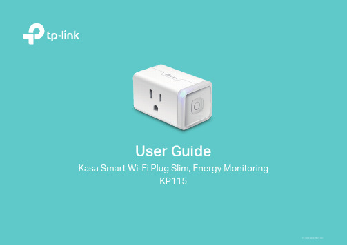
User GuideKasa Smart Wi-Fi Plug Slim, Energy MonitoringKP1151910012845 REV1.0.0ContentsAbout This Guide (1)Introduction (2)Appearance (3)Set Up Your Smart Wi-Fi Plug Slim (4)Main Device Controls (5)Configure Your Smart Wi-Fi Plug Slim (6)Create Scenes (8)Discover Kasa (9)Authentication (10)About This GuideThis guide provides a brief introduction to Kasa Smart Wi-Fi Plug Slim and the Kasa Smart app, as well as regulatory information.Please note that features of Kasa Smart Wi-Fi Plug Slim may vary slightly depending on the model and software version you have, and on your location, language and internet service provider. All images, steps, and descriptions in this guide are only examples and may not reflect your actual experience.ConventionsMore Info• Operating temperature, storage temperature, and other specifications can be found on the product page at https://.• Our T echnical Support and troubleshooting information can be found at https:///support/.• A TP-Link Community is provided for you to discuss our products at https://.1IntroductionKasa Smart Wi-Fi Plug Slim is a compact home device that turns your typical electrical wall outlet into a controllable, customizable and multi-functional outlet, enabling you to easily control your lights and household electronic devices via Kasa Smart app on your iOS or Android devices, no matter where you find yourself.Control from Anywhere Compact DesignNo Hub Required Home Automation• Control from Anywhere- Manages plugged-in electronics from anywhere with the Kasa Smart app.• Compact Design- Allows two plugs to be stacked in the same outlet.• No Hub Required- Connects to your home’s Wi-Fi network. No need for a hub or extra equipment.• Home Automation- Set multiple schedules, create scenes and groups, and simulate occupancy while away with away mode.Supported Load Types:Heater: ≤1500 W T oaster: ≤850 WHumidifier: ≤260 W T ower Fan: ≤50 WIron: ≤1500 W23Appearance Smart Wi-Fi Plug Slim has a control button to turn on/off devices plugged in, and LED to show you the current status. For detail information, see the explanation below:*KP115 (US version) is used for demonstration in this guide.Press to turn the socket ON or OFF.Press and hold (for 5 seconds) until the LED flashes amber and blue alternately to initiate the app configuring process (SoftAP).Press and hold (for 10 seconds) until the LED flashes amber rapidly to factory reset the Smart Plug Mini.Flashing amber and blue: App configuring process (SoftAP) initiated.Flashing blue rapidly: Connecting to the network.Solid blue: Connected to the network.Flashing amber rapidly: Factory reset.Solid amber: Initializing, rebooting, or no network connection.Off: The Smart Plug Mini is switched OFF.4Set Up Y our Smart Wi-Fi Plug Slim Follow the steps below to set up your smart plug via Kasa Smart app.1. Install Kasa Smart app Get the Kasa Smart app from Google Play orthe Apple App Store, or scan the QR code below to download it. 2. Log in or sign up with TP-Link ID Open the Kasa Smart app and log in withyour TP-Link ID. If you don’t have an account, create one first. 3. Add Device Tap the button in the Kasa Smart app, select Add a Device >Smart Plugs > SmartPlug Lite / Mini and then follow step-by-stepapp instructions to complete the setup.5Main Device Controls After you successfully set up your smart plug, you will see the home page of the Kasa Smart app. Here you can view and manage all devices that you've added to Kasa. T ap a smart plug to control and manage it.Home PageDevice Status6Configure Y our Smart Wi-Fi Plug Slim On Device Status page, you can set Schedule, preset Away Mode, set Timer, check Usage and change the settings of your smart plug.Set Schedule Tap to set a schedule for your smartplug to simplify your daily routine by creating automatic On/Off action.Preset Away ModeTapto preset the Away Mode and yoursmart plug will be randomly turned on/offduring this time.7Set TimerT ap to set the timer and your smart plug will automatically be turned on/off after the time ends.Device SettingsTap to view and change the settings ofyour smart plug. Check Usage Tap to view and track energy consumption.8Create Scenes A scene is a preset group of smart devices that can be programmed, customized and activated simultaneously at the touch of a button from your smartphone or tablet, allowing you to easily set your mood, activity or fit any special occasion. This page allows you to preset how your smart homedevices should act automatically at special occasions.Discover KasaUse the Kasa Smart app to pair your smart Wi-Fi plug with Amazon Alexa, Google Home Assistant, and enjoy a full hands-free experience. Kasa helps manage the rest of your smart home too, working with Samsung SmartThings to trigger changes when you arrive home or leave for the day. Launch the Kasa Smart app and go to Add Device > WORKS WITH KASA > Amazon Alexa / Google Assistant / Samsung SmartThings for detailedinstructions.9AuthenticationCOPYRIGHT & TRADEMARKSSpecifications are subject to change without notice. is a registered trademark of TP-Link T echnologies Co., Ltd. Other brands and product names are trademarks or registered trademarks of their respective holders.No part of the specifications may be reproduced in any form or by any means or used to make any derivative such as translation, transformation, or adaptation without permission from TP-Link T echnologies Co., Ltd. Copyright © 2020 TP-Link T echnologies Co., Ltd. All rights reserved.FCC compliance information statementProduct Name: Kasa Smart Wi-Fi Plug Slim, Energy MonitoringModel Number: KP115Responsible party:TP-Link USA Corporation, d/b/a TP-Link North America, Inc.Address: 145 South State College Blvd. Suite 400, Brea, CA 92821Website: /us/T el: +1 626 333 0234Fax: +1 909 527 6803E-mail: *********************This equipment has been tested and found to comply with the limits for a Class B digital device, pursuant to part 15 of the FCC Rules. These limits are designed to provide reasonable protection against harmful interference in a residential installation. This equipment generates, uses and can radiate radio frequency energy and, if not installed and used in accordance with the instructions, may cause harmful interference to radio communications. However, there is no guarantee that interference will not occur in a particular installation. If this equipment does cause harmful interference to radio or television reception, which can be determined by turning the equipment off and on, the user is encouraged to try to correct the interference by one or more of the following measures:• Reorient or relocate the receiving antenna.• Increase the separation between the equipment and receiver.• Connect the equipment into an outlet on a circuit different from that to which the receiver is connected.• Consult the dealer or an experienced radio/ TV technician for help.This device complies with part 15 of the FCC Rules. Operation is subject to the following two conditions:1. This device may not cause harmful interference.2. This device must accept any interference received, including interference that may cause undesired operation.Any changes or modifications not expressly approved by the party responsible for compliance could void the user’s authority to operate the equipment.Note: The manufacturer is not responsible for any radio or TV interference caused by unauthorized modifications to this equipment. Such modifications could void the user’s authority to operate the equipment.FCC RF Radiation Exposure StatementThis equipment complies with FCC RF radiation exposure limits set forth for an uncontrolled environment. This device and its antenna must not be co-located or operating in conjunction with any other antenna or transmitter.“T o comply with FCC RF exposure compliance requirements, this grant is applicable to only Mobile Configurations. The antennas used for this transmitter must be installed to provide a separation distance of at least 20 cm from all persons and must not be co-located or operating in conjunction with any other antenna or transmitter.”We, TP-Link USA Corporation, has determined that the equipment shown as above has been shown to comply with the applicable technical standards, FCC part 15. There is no unauthorized change is made in the equipment and the equipment is properly maintained and operated.Issue Date: 2020-07-06Canadian Compliance StatementThis device contains licence-exempt transmitter(s)/receiver(s) that comply with Innovation, Science and Economic Development Canada’s licence-exempt RSS(s). Operation is subject to the following two conditions:(1) This device may not cause interference.(2) This device must accept any interference, including interference that may cause undesired operation of the device.L’émetteur/récepteur exempt de licence contenu dans le présent appareil est conforme aux CNR d’Innovation, Sciences et Développement économique Canada applicables aux appareils radio exempts de licence. L’exploitation est autorisée aux deux conditions suivantes :1) L’appareil ne doit pas produire de brouillage;2) L’appareil doit accepter tout brouillage radioélectrique subi, même si le brouillage est susceptible d’en compromettre le fonctionnement. Radiation Exposure Statement:This equipment complies with IC radiation exposure limits set forth for an uncontrolled environment. This equipment should be installed and operated with minimum distance 20cm between the radiator & your body.Déclaration d’exposition aux radiations:Cet équipement est conforme aux limites d’exposition aux rayonnements IC établies pour un environnement non contrôlé. Cet équipement doit être installé et utilisé avec un minimum de 20 cm de distance entre la source de rayonnement et votre corps.Industry Canada StatementCAN ICES-3 (B)/NMB-3(B)Korea Warning Statements당해 무선설비는 운용중 전파혼신 가능성이 있음.NCC Notice注意!依據 低功率電波輻射性電機管理辦法第十二條 經型式認證合格之低功率射頻電機,非經許可,公司、商號或使用者均不得擅自變更頻率、加大功率或變更原設計之特性或功能。
Leviton 智能插座说明书
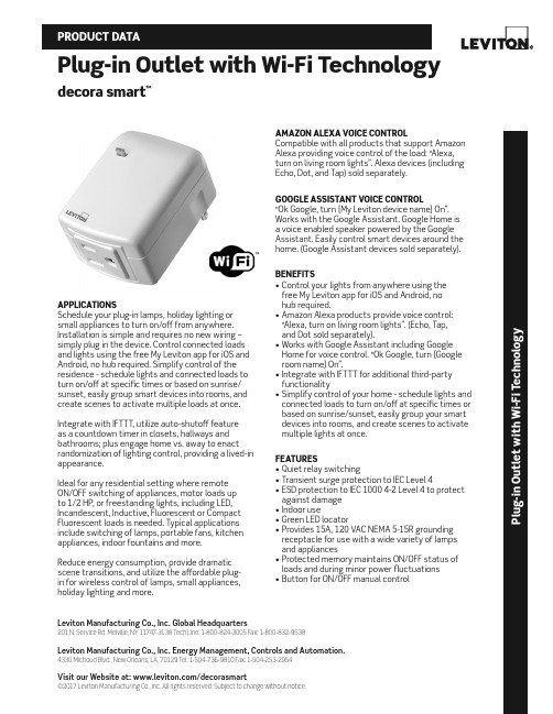
Leviton Manufacturing Co., Inc. Global Headquarters201 N. Service Rd. Melville, NY 11747-3138 Tech Line: 1-800-824-3005 Fax: 1-800-832-9538Leviton Manufacturing Co., Inc. Energy Management, Controls and Automation.4330 Michoud Blvd., New Orleans, LA, 70129 Tel: 1-504-736-9810 Fax: 1-504-253-2954Visit our Website at: /decorasmart©2017 Leviton Manufacturing Co., Inc. All rights reserved. Subject to change without notice.Plug-in Outlet with Wi-Fi Technologydecora smart ™P l u g -i n O u t l e t w i t h W i -F i T e c h n o l o g yAPPLICATIONSSchedule your plug-in lamps, holiday lighting or small appliances to turn on/off from anywhere. Installation is simple and requires no new wiring – simply plug in the device. Control connected loads and lights using the free My Leviton app for iOS and Android, no hub required. Simplify control of the residence - schedule lights and connected loads to turn on/off at specific times or based on sunrise/sunset, easily group smart devices into rooms, and create scenes to activate multiple loads at once.Integrate with IFTTT, utilize auto-shutoff feature as a countdown timer in closets, hallways and bathrooms; plus engage home vs. away to enact randomization of lighting control, providing a lived-in appearance.Ideal for any residential setting where remote ON/OFF switching of appliances, motor loads up to 1/2 HP, or freestanding lights, including LED, Incandescent, Inductive, Fluorescent or Compact Fluorescent loads is needed. Typical applications include switching of lamps, portable fans, kitchen appliances, indoor fountains and more.Reduce energy consumption, provide dramatic scene transitions, and utilize the affordable plug-in for wireless control of lamps, small appliances, holiday lighting and more.AMAZON ALEXA VOICE CONTROLCompatible with all products that support Amazon Alexa providing voice control of the load: “Alexa, turn on living room lights”. Alexa devices (including Echo, Dot, and Tap) sold separately.GOOGLE ASSISTANT VOICE CONTROL“Ok Google, turn [My Leviton device name] On”. Works with the Google Assistant. Google Home is a voice enabled speaker powered by the Google Assistant. Easily control smart devices around the home. (Google Assistant devices sold separately).BENEFITS• Control your lights from anywhere using the free My Leviton app for iOS and Android, no hub required.• Amazon Alexa products provide voice control: “Alexa, turn on living room lights”. (Echo, Tap, and Dot sold separately).• Works with Google Assistant including Google Home for voice control. “Ok Google, turn [Google room name] On”.• Integrate with IFTTT for additional third-party functionality• Simplify control of your home - schedule lights and connected loads to turn on/off at specific times or based on sunrise/sunset, easily group your smart devices into rooms, and create scenes to activate multiple lights at once.FEATURES• Quiet relay switching• Transient surge protection to IEC Level 4• ESD protection to IEC 1000 4-2 Level 4 to protect against damage • Indoor use• Green LED locator• Provides 15A, 120 VAC NEMA 5-15R grounding receptacle for use with a wide variety of lamps and appliances• Protected memory maintains ON/OFF status of loads and during minor power fluctuations• Button for ON/OFF manual controlSAT-10111REV JUL 2017Leviton Manufacturing Co., Inc. Global Headquarters201 N. Service Rd. Melville, NY 11747-3138 Tech Line: 1-800-824-3005 Fax: 1-800-832-9538Leviton Manufacturing Co., Inc. Energy Management, Controls and Automation.4330 Michoud Blvd., New Orleans, LA, 70129 Tel: 1-504-736-9810 Fax: 1-504-253-2954Visit our Website at: /decorasmart©2017 Leviton Manufacturing Co., Inc. All rights reserved. Subject to change without notice.PRODUCT DATADRAWING DW15ARATINGS• 120 VAC, 60 Hz• 1800W Incandescent • 5A LED/CFL• 1800VA Fluorescent • 15A Resistive • 1/2 HP MotorAGENCY STANDARDS AND COMPLIANCE • Complies with UL 917• CSA Certified (File #003413)• NOM-ANCE Certified • Wi-Fi CERTIFIED™• Complies with FCC Part 15, Class BWARRANTY INFORMATION • Five-Year Limited WarrantyORDERING INFORMATION。
LCDG-ZJ1-62610 WIFI智能插座使用说明书V1.01

LCDG-ZJ1-62610 WIFI 智能插座使用说明书
一、产品简介
LCDG-ZJ1-62610 WIFI 智能插座能够实现常规的电气转接功能,能够测量用电器(负载) 的电压、电流、功率、功率因数及计量负载的用电量和 CO 2 排量等参数,本产品具有 wifi 通讯接口,可以非常便捷的实现远程查询控制,方便直观地掌握电器的工作状态及耗电量。
请用户严格按照本说明书说明安装和使用本产品,以获得最佳使用效果。
安全须知
在试图安装、操作或维护此设备之前,请仔细阅读本手册,拿到它并逐步熟悉这种 仪表。以下特殊信息可能贯穿出现在本手册中或在设备上,用来。
附有这种安全标志示意周围存在着电力危险,假若未遵照一定的指令将会导致人身 伤害。
LCDG-ZJ1-62610 WIFI 智能插座 使用说明书
编制: bzf 校对: 批准:
序言
感谢您选用山东力创科技股份有限公司的 LCDG-ZJ1-62610 WIFI 智能插座。我们建议在 安装、操作或维护此设备之前,请仔细阅读本手册,并逐步熟悉这种插座。以下特殊信息可 能贯穿出现在本手册中或在设备上,用来警示潜在的危险或用于阐释和规定操作规程,请注 意。
© 2016 Shandong Lichuang Science & Technology Co.,Ltd 版权所有
本出版物中所包含的信息仅为所显示的目的而制作。 没有本公司的书面同意,本手册及随同 LCDG-ZJ1-62610 WIFI 智能插座设备一起提供的 其他文件不得被复制,不管是部分或全部。 用于描述设备的图纸及图片仅作为一般参考作用,而不能确保每个细节的完整性与准确 性.。 本手册对应的相关内容如有更改,恕不另行通知。订货前,请垂询本公司或当地经销商 以获悉本产品的最新规格。
T4高清无线遥控插座摄像机(中英文)操作说明书
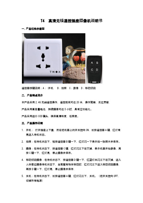
T4 高清无线遥控插座摄像机说明书一.产品结构示意图遥控器按键说明:A::开机 B:拍照 C:录像 D:移动侦测二.产品特点简介本产品采用2.4G无线遥控操作,遥控距离可达20米,操作简单,反应灵敏.产品采用高容量电池,持续摄像可达5小时,具有过功能化。
产品采用进口CCD镜头,确保高清晰度,低照度。
三.产品操作说明1.开机:打开插座上下盖,然后把机器上的开关拨向ON,长按遥控器A键,红灯常亮进入待机状态。
2.拍照:在待机状态下,短按遥控器B键一下,红灯闪一下表示拍一张照片并保存。
3.摄像:在待机状态下,按遥控器C键,红灯闪三下后灭掉,表示机器开始录像,再按C键一下,红灯亮,停止摄像并保存。
4.移动侦测摄像:在待机状态下,按遥控器D键一下,红蓝灯共闪三下后灭掉,进入人体感应摄像待机状态下,当周围有物体移动时,红灯闪三下进入移动侦测摄像,再按D键一下,红灯亮,停止摄像并保存.5.关机:在待机状态下,长按遥控器A键,红灯闪三下,关机。
(把开关拨向OFF,切掉所有电源)B连接电脑:USB连接电脑即,打开可移动磁盘即可读取文件。
7.充电:USB连接电脑充电,或者连接充电器充电都可以,充电时红灯闪烁,充满电后红灯常亮。
8 时间修改设置:在机器中插入TF卡,连接电脑,在可移动硬盘中打开“Time”文档,把文档中的时间改为当前时间即可, 然后保存“Time”文件。
保存完文件后安全退出硬件,开机,时间设置完成。
时间设置好后,录像文件的时间水印就与你设置的时间一致了。
四.产品参数:HD-001 High Digital Remote control Induction of human Power switch Manual 一.HD-001 Structure picture二.HD-001FeaturesThis product uses 2.4G wireless remote control, remote control distance of up to 20 meters, including the curve reflects the simple, responsive.The Product has a real human body sensor module, the human body sensing distance of 5 meters, high sensitivityThe Products using high-capacity battery, continuous recording up to 5 hours of recording time without the human body sensor。
NETGEAR FS605v3 光纤网络插座操作手册说明书

Certyfikaty instytucji ds. bezpieczeństwa
Znak CE
Wrzesień 2012 r.
Aby zapoznać się z kompletną deklaracją zgodności UE, odwiedź stronę /app/answers/detail/a_id/11621/.
Ten symbol został umieszczony zgodnie z dyrektywą Unii Europejskiej 2002/96 w sprawie zużytego sprzętu elektrycznego i elektronicznego (WEEE). Jeśli produkt jest utylizowany na terenie Unii Europejskiej, powinien on być traktowany i poddany recyklingowi zgodnie z obowiązującym lokalnie prawem oraz z zastosowaniem postanowień dyrektywy WEEE. NETGEAR, logo NETGEAR oraz Connect with Innovation są znakami towarowymi oraz/lub zarejestrowanymi znakami towarowymi należącymi do firmy NETGEAR Inc. oraz/lub jej spółek zależnych w USA oraz/lub innych państwach. Informacje mogą ulec zmianie bez powiadomienia. Pozostałe nazwy marek i produktów są znakami towarowymi lub zarejestrowanymi znakami towarowymi należącymi do ich prawnych właścicieli. © NETGEAR, Inc. Wszelkie prawa zastrzeżone. Tylko do użytku wewnętrznego na terenie państw UE i Szwajcarii.
智能插座使用方法
智能插座使用方法关键信息项:1、智能插座的基本功能介绍2、适用的电器类型3、安装与连接步骤4、手机 APP 控制操作说明5、安全注意事项6、故障排除方法7、售后服务与质保条款1、智能插座的基本功能介绍11 智能插座具备远程控制功能,用户可通过手机或其他智能设备在任何有网络的地方控制插座的开关状态。
12 具有定时开关功能,用户能够预先设置插座的开启和关闭时间,实现自动化控制。
13 支持电量统计功能,可监测连接电器的用电量,并提供相应的数据记录。
2、适用的电器类型21 智能插座适用于一般家庭常用的小功率电器,如台灯、风扇、充电器等。
22 但不适用于大功率电器,如空调、电热水器、电暖器等,以免造成过载和安全隐患。
3、安装与连接步骤31 首先,确保安装位置干燥、通风,并远离水源和火源。
32 将智能插座插入标准的电源插座中,确保插头与插座接触良好。
33 下载并安装对应的手机 APP,根据 APP 提示进行注册和登录。
34 打开手机的蓝牙或 WiFi 功能,在 APP 中搜索并连接智能插座。
4、手机 APP 控制操作说明41 打开已安装的 APP,在设备列表中找到对应的智能插座。
42 点击插座图标,可实现远程开启或关闭插座电源。
43 进入定时设置页面,选择需要设定的时间和重复周期,即可完成定时开关的设置。
44 查看电量统计页面,了解连接电器的用电情况。
5、安全注意事项51 请勿在潮湿或有易燃、易爆物品的环境中使用智能插座。
52 避免儿童接触智能插座,以防发生意外。
53 不要私自拆卸或改装智能插座,以免造成损坏和安全风险。
54 当插座出现异常发热、冒烟等情况时,应立即停止使用,并切断电源。
6、故障排除方法61 如果智能插座无法连接手机 APP,首先检查手机网络和蓝牙/WiFi 设置是否正常,然后尝试重启插座和手机。
62 若插座无法正常开关,检查电器是否过载,或者尝试重置插座。
63 电量统计数据不准确时,可检查插座与电器的连接是否稳定。
Edimax智能插座系列说明说明书
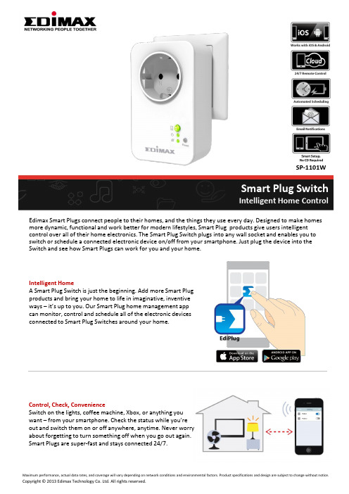
Intelligent HomeA Smart Plug Switch is just the beginning. Add more Smart Plug products and bring your home to life in imaginative, inventive ways – it’s up to you. Our Smart Plug home management app can monitor, control and schedule all of the electronic devices connected to Smart Plug Switches around your home.Edimax Smart Plugs connect people to their homes, and the things they use every day. Designed to make homes more dynamic, functional and work better for modern lifestyles, Smart Plug products give users intelligent control over all of their home electronics. The Smart Plug Switch plugs into any wall socket and enables you to switch or schedule a connected electronic device on/off from your smartphone. Just plug the device into the Switch and see how Smart Plugs can work for you and your home.Smart Plug SwitchIntelligent Home ControlControl, Check, ConvenienceSwitch on the lights, coffee machine, Xbox, or anything you want – from your smartphone. Check the status while you’re out and switch them on or off anywhere, anytime. Never worry about forgetting to turn something off when you go out again. Smart Plugs are super-fast and stays connected 24/7.SP-1101WSchedule, SaveProgram intelligent schedules to make your home smarter and more energy efficient. Our Smart Plug Switch was developed to suit your lifestyle. Schedule your lights so it’s light when you get home or when you wake up in the morning. Schedule your lamp or coffee machine if youlike – Smart Plugs can schedule anything in your home to work in better ways for you and your life.SOFTWARE FEATURES•Easily switch on/off via iPhone, iPad, Android•Manual or scheduled controls•Email notifications after switching on/off via app •Wireless installation using a smart phone/tablet ADVANTAGES•Save: Save time and power•Easy: Manage your home electronics anywhere / anytime •Smart: Control your appliances from your smartphone or tablet Intelligent Home ControlSP-1101WEasy Setup & Smart NotificationsSetup couldn’t be any easier and is all done on your smartphone or tablet. Once the Smart Plug is up and running, email notifications can keep you updated about which appliances and electronics are switched on/off via the EdiPlug app. Make sure your intelligent home is working properly and keep track of what’s going on in a busy, family home.Electrical Communication RF Output PowerOperating Voltage: 100–240VAC Power Frequency: 50–60Hz Max. Load Capacity:EU: 16A/230VAC;UK: 13A/240VAC AU: 10A/240VAC;US: 15A/120VAC Wireless IEEE 802.11b/g/nCoverage: Up to 10MFrequency Band: 2.4000 –2.4835GHzWi-Fi Security: WEP,WPA/WPA2,WPSProtocol: Client UDP, TCP/IP, HTTP11n: Up to 150Mbps(dynamic)11g: Up to 54Mbps(dynamic)11b: Up to 11Mbps(dynamic)Modulation Technology DBPSK,DQPSK, CCK, OFDM, 16-QAM, 64-QAMManagement Interface EnvironmentFirmware upgradable iPhone & iPad app Android appRemote access (Internet) Email notifications Schedule control LED Indicator: Power, Switch,NetworkButtons: Reset, Switch32°F–104°F (0°C–40°C)5–80%RH (non-condensing)Indoor use onlyDimensions Weight Certification 105mm (L) x 64mm (W) x 60mm (H) 184g CE, FCC, LVDCOMPATIABLE PLUG TYPES SP-1101WTECHNICAL SPECIFICATIONSHARDWARE INTERFACEIntelligent Home Control。
ZigBee无线一路智能插座操作说明
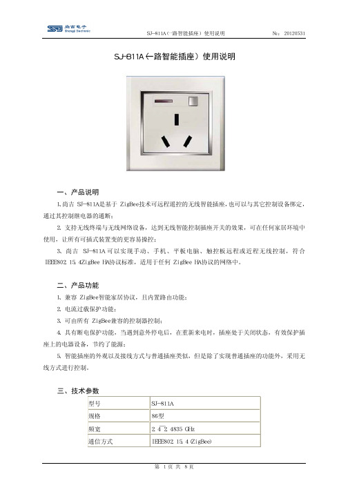
SJ-811A(一路智能插座)使用说明 一、产品说明 1、尚吉SJ-811A是基于ZigBee技术可远程遥控的无线智能插座,也可以与其它控制设备绑定,通过其控制继电器的通断; 2、支持无线终端与无线网络设备,达到无线智能控制插座开关的效果,可在任何家居环境中使用,让所有可插式装置变的更容易操控; 3、尚吉SJ-811A可以实现手动、手机、平板电脑、触控板远程或近程无线控制,符合IEEE802.15.4ZigBee HA协议标准,适用于任何ZigBee HA协议的网络中。
二、产品功能 1、兼容ZigBee智能家居协议,且内置路由功能; 2、电流过载保护功能; 3、可由所有ZigBee兼容的控制器控制; 4、具有断电保护功能,当遇到意外停电后,在重新来电时,插座处于关闭状态,有效保护插座上的电器设备,节约了能源; 5、智能插座的外观以及接线方式与普通插座类似,但是除了实现普通插座的功能外,采用无线方式进行控制。
三、技术参数 型号 SJ-811A 规格 86型 频宽 2.4 ̄2.4835 GHz 通信方式 IEEE802.15.4(ZigBee) 通信距离 50m 工作温度 -10 ̄50℃ 工作湿度 最大95%RH 供电电压 110 ̄220 VAC 50/60 Hz 电源供电 额定电流 10A 颜色 雅白色 材质 阻燃PC料 产品尺寸 86mmx86mmx45mm 四、安装说明 1、易于安装和使用,完全兼容现有标准插座; 2、零火线安装,首先必须切断电源(严禁带电操作); 3、背面接线柱的接线说明: ①“L”接线柱——连接220V电源的火线; ②“N”接线柱——连接220V电源的零线; ③“A”接线柱——连接插孔的线路; 3、安装:按照说明接线完毕后,将插座放入接线盒中,用螺钉将开关的底板固定到接线盒上,盖上触摸面板安装完毕。
4、软件安装:光盘或是网上下载(安卓系统、Apple系统)适合的本机软件直接安装。
Eaton Brightlayer Home智能插座说明书
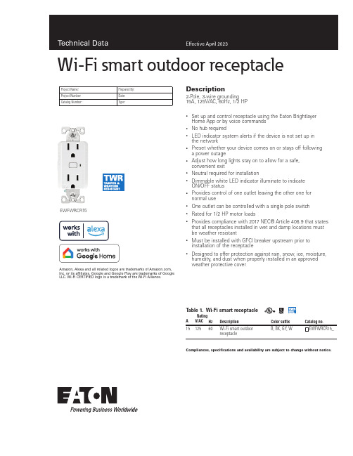
Description2-Pole, 3-wire grounding 15A, 125V/AC, 60Hz, 1/2 HP• Set up and control receptacle using the Eaton Brightlayer Home App or by voice commands • No hub required• LED indicator system alerts if the device is not set up in the network• Preset whether your device comes on or stays off following a power outage• Adjust how long lights stay on to allow for a safe, convenient exit• Neutral required for installation• Dimmable white LED indicator illuminate to indicate ON/OFF status•Provides control of one outlet leaving the other one for normal use• One outlet can be controlled with a single pole switch • Rated for 1/2 HP motor loads•Provides compliance with 2017 NEC® Article 406.9 that states that all receptacles installed in wet and damp locations must be weather resistant•Must be installed with GFCI breaker upstream prior to installation of the receptacle•Designed to offer protection against rain, snow, ice, moisture, humidity, and dust when properly installed in an approved weather protective coverEWFWRCR15Project Name:Prepared By:Project Number:Date:Catalog Number:Type:Compliances, specifications and availability are subject to change without notice.T able 1. Wi-Fi smart receptacleRating DescriptionColor suffixCatalog no.AV/AC Hz1512560Wi-Fi smart outdoor receptacleB, BK, GY, W EWFWRCR15_Amazon, Alexa and all related logos are trademarks of , Inc. or its affiliates. Google and Google Play are trademarks of GoogleLLC. Wi-Fi CERTIFIED logo is a trademark of the Wi-Fi Alliance.Wi-Fi smart outdoor receptacleEATON /smarthome Wi-Fi smart outdoor receptacleTechnical DataEffective April 2023Compliances, specifications and availability are subject to change without notice.Eaton’s Wi-Fi smart outdoor receptacle replaces regular receptacles to provide local and remote ON/OFF control of a single outlet. The receptacle can be remotely controlled and the user can create routines, schedules and group devices using the Eaton Brightlayer Home App. Ideal for controlling outdoor appliances, pool pumps, and holiday lights, making your outdoor space more livable.ApplicationsProject Name:Prepared By:Project Number:Date:Catalog Number:Type:T able 2. SpecificationsCatalog No.EWFWRCR15PerformanceMaximum amperage for receptacle is 15A Rating: 125V/AC, 60Hz Horsepower rating: 1/2 HPInstallation & Programming Please reference the Instruction Sheet included with the product for wiring installation. For programming of the device, see the Quick Start Guide Testing & Code Compliance cULus Listed Appliance Control 38DS. Tested per UL498 and UL498B. NOM Certified. Complies with FCC part 15, class B.TerminationsReceptacles have four screw terminals for line, neutral, ground and 3-way Material Characteristics Flammability: Meets UL94 requirements; V2 ratedTemperature Rating: -4 degrees F to 140 degrees F (-20 degrees C to 60 degrees C)Warranty2-year limited product warrantyT able 3. Color ordering informationFor ordering devices, include Catalog No. followed by the Color Suffix: B (Brown), BK (Black), GY (Gray), W (White).Color options:(Brown)(Black)(Gray)(White)Figure 1. EWFWRCR15Product dimensionsTechnical Data Effective April 2023Wi-Fi smart outdoor receptacleProject Name:Prepared By:Project Number:Date:Catalog Number:Type:Single location control installationKEY:cULus NOM FCCTwo location control installationusing a 3-way switchRelated productsWi-Fi smart productsEWFTRCR15, EWFSW15, EWFD30Compliances, specifications and availability are subject to change without notice.WallplatesPJS26, PJS262Weather protective coversWIUX-1CL, WIUX-2CLElectrical Sector1123 Hwy 74 SPeachtree City, GA 30269United States/WifiSmartElectrical SectorCanada Operations5925 McLaughlin RoadMississauga, Ontario, L5R 1B8CanadaEatonCanada.ca/WifiSmartElectrical SectorMexico OperationsCarr. Tlalnepantla -Cuautitlan Km 17.8 s/nCol. Villa Jardin esq.Cerrada 8 de MayoCuautitlan, Mexico CP 54800MexicoEaton.mx/WifiSmartEaton1000 Eaton BoulevardCleveland, OH 44122United StatesEaton is a registered trademark.All other trademarks are propertyof their respective owners.© 2023 EatonAll Rights ReservedPrinted in USAPublication No. TD610149ENApril 2023。
WR-UMRF RPSMA 斜角插座说明书
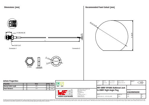
636209050200636209050200636209050200636209050200Cautions and Warnings:The following conditions apply to all goods within the product series of the Connectors of Würth Elektronik eiSos GmbH & Co. KG:General:•This mechanical component is designed and manufactured for use in general electronic equipment.•Würth Elektronik must be asked for written approval (following the PPAP procedure) before incorporating the components into any equipment in fields such as military, aerospace, aviation, nuclear control, submarine, transportation (automotive control, train control, ship control), transportation signal, disaster prevention, medical, public information network, etc. where higher safety and reliability are especially required and/or if there is the possibility of direct damage or human injury.•Mechanical components that will be used in safety-critical or high-reliability applications, should be pre-evaluated by the customer.•The mechanical component is designed and manufactured to be used within the datasheet specified values. If the usage and operation conditions specified in the datasheet are not met, the component may be damaged or dissolved.•Do not drop or impact the components, the component may be damaged.•Prevent any damage or scratches on the component, especially on the actuator.•Direct mechanical impact to the product shall be prevented (e.g overlapping of the PCB´s).•Würth Elektronik products are qualified according to international standards, which are listed in each product reliability report. Würth Elektronik does not warrant any customer qualified product characteristics beyond Würth Elektroniks’ specifications, for its validity and sustainability over time.•The responsibility for the applicability of the customer specific products and use in a particular customer design is always within the authority of the customer. All technical specifications for standard products do also apply to customer specific products.•The mechanical component is designed to be used along with Würth Elektronik counterparts and tools. Würth Elektronik cannot ensure the reliability of these components while being used with other products.Product Specific:Soldering:•The solder profile must comply with the technical product specifications. All other profiles will void the warranty.•All other soldering methods are at the customers’ own risk.Cleaning and Washing:•Washing agents used during the production to clean the customer application might damage or change the characteristics of the component, body, pins and termination. Washing agents may have a negative effect on the long-term functionality of the product.•Using a brush during the cleaning process may deform function relevant areas. Therefore, we do not recommend using a brush during the PCB cleaning process.Potting and Coating:•If the product is potted in the customer application, the potting material might shrink or expand during and after hardening. Shrinking could lead to an incomplete seal, allowing contaminants into the components. Expansion could damage the components. Werecommend a manual inspection after potting or coating to avoid these effects.Storage Conditions:• A storage of Würth Elektronik products for longer than 12 months is not recommended. Within other effects, the terminals may suffer degradation, resulting in bad solderability. Therefore, all products shall be used within the period of 12 months based on the day of shipment.•Do not expose the components to direct sunlight.•The storage conditions in the original packaging are defined according to DIN EN 61760-2.•The storage conditions stated in the original packaging apply to the storage time and not to the transportation time of the components. Handling:•Do not repeatedly operate the component with excessive force. It may damage or deform the component resulting in malfunction.•In the case a product requires particular handling precautions, in addition to the general recommendations mentioned here before, these will appear on the product datasheet.These cautions and warnings comply with the state of the scientific and technical knowledge and are believed to be accurate and reliable.However, no responsibility is assumed for inaccuracies or incompleteness.Würth Elektronik eiSos GmbH & Co. KGEMC & Inductive SolutionsMax-Eyth-Str. 174638 WaldenburgGermanyCHECKED REVISION DATE (YYYY-MM-DD)GENERAL TOLERANCE PROJECTIONMETHODJTs001.0002020-10-27DIN ISO 2768-1mDESCRIPTIONWR-UMRF RPSMA Bulkhead Jackto UMRF Right Angle Plug ORDER CODE636209050200SIZE/TYPE BUSINESS UNIT STATUS PAGEImportant NotesThe following conditions apply to all goods within the product range of Würth Elektronik eiSos GmbH & Co. KG:1. General Customer ResponsibilitySome goods within the product range of Würth Elektronik eiSos GmbH & Co. KG contain statements regarding general suitability for certain application areas. These statements about suitability are based on our knowledge and experience of typical requirements concerning the areas, serve as general guidance and cannot be estimated as binding statements about the suitability for a customer application. The responsibility for the applicability and use in a particular customer design is always solely within the authority of the customer. Due to this fact it is up to the customer to evaluate, where appropriate to investigate and decide whether the device with the specific product characteristics described in the product specification is valid and suitable for the respective customer application or not.2. Customer Responsibility related to Specific, in particular Safety-Relevant ApplicationsIt has to be clearly pointed out that the possibility of a malfunction of electronic components or failure before the end of the usual lifetime cannot be completely eliminated in the current state of the art, even if the products are operated within the range of the specifications.In certain customer applications requiring a very high level of safety and especially in customer applications in which the malfunction or failure of an electronic component could endanger human life or health it must be ensured by most advanced technological aid of suitable design of the customer application that no injury or damage is caused to third parties in the event of malfunction or failure of an electronic component. Therefore, customer is cautioned to verify that data sheets are current before placing orders. The current data sheets can be downloaded at .3. Best Care and AttentionAny product-specific notes, cautions and warnings must be strictly observed. Any disregard will result in the loss of warranty.4. Customer Support for Product SpecificationsSome products within the product range may contain substances which are subject to restrictions in certain jurisdictions in order to serve specific technical requirements. Necessary information is available on request. In this case the field sales engineer or the internal sales person in charge should be contacted who will be happy to support in this matter.5. Product R&DDue to constant product improvement product specifications may change from time to time. As a standard reporting procedure of the Product Change Notification (PCN) according to the JEDEC-Standard inform about minor and major changes. In case of further queries regarding the PCN, the field sales engineer or the internal sales person in charge should be contacted. The basic responsibility of the customer as per Section 1 and 2 remains unaffected.6. Product Life CycleDue to technical progress and economical evaluation we also reserve the right to discontinue production and delivery of products. As a standard reporting procedure of the Product Termination Notification (PTN) according to the JEDEC-Standard we will inform at an early stage about inevitable product discontinuance. According to this we cannot guarantee that all products within our product range will always be available. Therefore it needs to be verified with the field sales engineer or the internal sales person in charge about the current product availability expectancy before or when the product for application design-in disposal is considered. The approach named above does not apply in the case of individual agreements deviating from the foregoing for customer-specific products.7. Property RightsAll the rights for contractual products produced by Würth Elektronik eiSos GmbH & Co. KG on the basis of ideas, development contracts as well as models or templates that are subject to copyright, patent or commercial protection supplied to the customer will remain with Würth Elektronik eiSos GmbH & Co. KG. Würth Elektronik eiSos GmbH & Co. KG does not warrant or represent that any license, either expressed or implied, is granted under any patent right, copyright, mask work right, or other intellectual property right relating to any combination, application, or process in which Würth Elektronik eiSos GmbH & Co. KG components or services are used.8. General Terms and ConditionsUnless otherwise agreed in individual contracts, all orders are subject to the current version of the “General Terms and Conditions of Würth Elektronik eiSos Group”, last version available at .Würth Elektronik eiSos GmbH & Co. KGEMC & Inductive SolutionsMax-Eyth-Str. 174638 WaldenburgGermanyCHECKED REVISION DATE (YYYY-MM-DD)GENERAL TOLERANCE PROJECTIONMETHODJTs001.0002020-10-27DIN ISO 2768-1mDESCRIPTIONWR-UMRF RPSMA Bulkhead Jackto UMRF Right Angle Plug ORDER CODE636209050200SIZE/TYPE BUSINESS UNIT STATUS PAGE。
艾顿Wi-Fi智能插座(EWFTRCR15)说明书
Control your lights and appliances from anywhere with Eaton’s Wi-Fi Smart Receptacle (EWFTRCR15) which replaces standard receptacles and features Wi-Fi control of bottom outlet while leaving the other outlet for normal operation. The receptacle can be remotely controlled using the Brightlayer Home App.Eaton’s Wi-Fi Smart Receptacle (EWFTRCR15) has additional features such as the ability to preset the device so that it can either come on or stay off following a power outage.Your Wi-Fi Smart ReceptacleFeaturesON/OFF ButtonSingle location installation (for two location installation see back page)Operation instructionsPrior to installationEnd User license agreementSoftware included with the Eaton product is hereby licensed to You, and Eaton retains for itself (or, if applica-ble, its suppliers) all title and ownership to any software delivered hereunder. Without Eaton’s authorization, You shall not copy, disclose or display the software, or otherwise make it available to others, and shall not attempt any sale, transfer, sublicense, reverse compilation or disassembly or redistribu-tion of the software. By using the software, You agree to the terms of Eaton’s End User License Agreement at: https:///WiFiSmartEULA ELECTRICAL RATINGSCurrent Capacity: 15Amps | Voltage: 125Vac | Horsepower: 1/2HP | Frequency: 60HzNeutral is requiredSeamless look with black TR shuttersLighting control Appliance controlProvides Wi-Fi control of bottom outlet while leaving the other outlet for normaloperationSafely leave room before lights turn OFFLED Status indicatorRequires neutral for installationWARNINGS AND CAUTIONS:• T urn OFF circuit breaker or remove fuse(s) and test that power is OFF before installation process • N ever wire any electrical device with power turned ON Wiring receptacle HOT may cause permanent damage to receptacle and void warranty • I f you are not sure about any part of theseinstructions, please contact a licensed electrician CAUTION• Use only with 120V/AC 60Hz• Do not exceed maximum rating of receptacle as indicated on the device.• M ust be installed and used in accordance with all national and local electrical codes • I f a bare copper or green ground connection is not available in the wallbox, contact a licensed electrician for installation • U se only #14 or #12 copper wire rated for at least 75ºC with these devicesDO NOT USE WITH ALUMINUM WIREIMPORTANT: Wi-Fi Smart Receptacle (EWFTRCR15) will not work or will be damaged if wired incorrectly and warranty will be voided. Refer to wiring instructions provided.NOTE: For Multi-location applications (3-way) a 3-way toggle receptacle can be used along with the Wi-Fi Smart Recep-tacle (EWFTRCR15).Quick Start Voice controlw ith Alexa and H ey Googleinstallation requiredSet schedules, groups, and scenesTools neededAdditional system requirementsPhillips-head ScrewdriverWire cuttersTools required for installation (not included)for the Wi-Fi Smart Receptacle (EWFTRCR15):A 2.4GHz Wi-Fi network with high-speed internetIOS 12.0 or later or Android 8.0 or later mobile device. Note: Must be connected to Wi-Fi and Bluetooth A Brightlayer Home account set-up through the Brightlayer Home App• P ress the ON/OFF button to turn the load ON• P ress the ON/OFF button again to turn the load OFF• W hen load is ON, press and hold the ON/OFF button for2 seconds until the LED indicator starts blinkingAfter 10 seconds, the load will turn OFFFACTORY RESET: The receptacle can be reset which willexclude the device from its network and restore allfactory defaults.• P ress and hold the ON/OFF button until the LEDindicator blinks for the fourth time (30 secs)• R elease the button • T he LED indicator will start blinking at a normal rate indicating the receptacle is not part of a Wi-Fi networkScan for more advanced featuresincluding adjusting the brightness level of the LED indicators and additional wiring configurationsFor color change kit installation instructions, see back pageWi-Fi Smart Devices offer reliability with unbeatable ease o f setup. /smarthomeEWFSW15EWFTRCR15EWACDEWFFSC15Amazon, Alexa and all related logos are trademarks of , Inc. or its affiliates. Google and Google Play are trademarks of Google LLC. Wi-Fi CERTIFIED logo is a trademark of the Wi-Fi Alliance.Contact us:/chat/smarthome*********************Phone (Toll Free): 877-386-2273 Device support: Option 5 then Option 3App support: Option 2 then Option 9 Fax (Toll Free): 800-329-3055FCC STATEMENTThis device complies with Part 15 of the FCC Rules. Operation is subject to the following two conditions:1: This device may not cause harmful interference, and2: This device must accept any interference received, including interference that may cause undesired operation.NOTE: This equipment has been tested and found to comply with the limits for aClass B digital device, pursuant to Part 15 of the FCC Rules. These limits are designed to provide reasonable protection against harmful interference in a residentialinstallation. This equipment generates, uses and can radiate radio frequency energy and, if not installed and used in accordance with the instructions, may cause harmful interference to radio communications. However, there is no guarantee that interfer-ence will not occur in a particular installation. If this equipment does cause harmful interference to radio or television reception, which can be determined by turning the equipment off and on, the user is encouraged to try to correct the interference by one or more of the following measures:• Reorient or relocate the receiving antenna.• Increase the separation between the equipment and receiver.• Connect the equipment into an outlet on a circuit different from that to which the receiver is connected.• Consult the dealer or an experienced radio/TV technician for help.FCC CAUTION: Any changes or modifications not expressly approved by Eaton Wiring Devices could void the user’s authority to operate the equipment.This device complies with Industry Canada’s license-exempt RSSs. Operation is subject to the following two conditions:(1) This device may not cause interference; and(2) This device must accept any interference, including interference that may cause undesired operation of the device.EATON WIRING DEVICES LIMITED 2 YEAR WARRANTYEaton Wiring Devices warrants its Receptacle to be free of defects in materials and workmanship in normal use and service for a period of two years from date of original purchase. THIS TWO (2) YEAR LIMITED WARRANTY IS IN LIEU OF ALL OTHER WARRANTIES, OBLIGATIONS, OR LIABILITIES, EXPRESSED OR IMPLIED (INCLUDING ANY IMPLIED WARRANTY OF MERCHANTABILITY OR FITNESS FOR A PARTICULAR PURPOSE THAT IS IN DURATION IN EXCESS OF TWO YEARS FROM THE DATE OF ORIGINAL CONSUMER PURCHASE). NO AGENT, REPRESENTATIVE, OR EMPLOYEE OF EATON HAS AUTHORITY TO INCREASE OR ALTER THE OBLIGATIONS OF EATON UNDER THIS WARRANTY. To obtain warranty service for any properly installed Eaton Receptacle that proves defective in normal use send the defective Receptacle prepaid and insured to Quality Control Dept., Eaton Wiring Devices, 203 Cooper Circle, Peachtree City, GA 30269; in Canada: Eaton Wiring Devices, 5925 McLaughlin Road, Mississauga, Ontario L5R 1B8. Eaton will repair or replace the defective unit, at its option. Eaton will not be responsible under this warranty if examination shows that the defective condition of the unit was caused by misuse, abuse, improper installation, alteration, improper maintenance or repair of damageTroubleshooting guideWarrantyLED statusHow to download the AppGet your Wi-Fi Smart Device running in 3 easy steps!Set-up the Device Add your device to the Brightlayer Home AppSTEP 1 : Double click on the “ON” button on the Wi-Fi Smart Receptacle (EWFTRCR15). Status LED on the Wi-Fi Smart Receptacle should be blinking cyan to indicate that the device is in set-up mode. If the status LED is not blinking, refer to the Troubleshooting guide.STEP 2 : Log in to your account on the Brightlayer Home AppSTEP 3 : Select “Devices” optionOnce initial device is installed, additional devices can be added using the global add (+) button.Once selected the devices would be displayed as shown below:Note: Now the user can utilize many features that are available such as creating schedules, scenes, preset light levels and minimum/maximum brightness settings through the Brightlayer Home App.Next click on “Add a Device” option shown in the screen belowSelect the device type to addSTEP 3 (continued) :Amazon, Alexa and all related logos are trademarks of , Inc. or its affiliates. Google and Google Play are trademarks of Google LLC. Wi-Fi CERTIFIED logo is a trademark of the Wi-Fi Alliance.STEP 3 (continued) :SymptomPossible CauseSolutionDevice doesn’t function. All LEDs are OFFA)B) C) Circuit breaker is open or tripped Improper wiring Defective receptacle A) B) C) Turn ON/Close the circuit breakerCheck and correct wiring Replace receptacle Erratic operation orflickering LEDsLoose wiring connectionsCheck wiring and following instructions provided with the deviceDevice functions normally using the receptacle push buttons but not from Brightlayer Home App. Purple LED indicator is blinking ON and OFF about once per secondReceptacle is not included in the Wi-Fi networkA) B) C) Include the receptacle in the Wi-Fi network using Brightlayer Home App Check that the router is functioning properly Go through the factory reset procedure and re-add the device to the Brightlayer Home App Device functions normally using the receptacle push buttons but not from Brightlayer Home App. Yellow LED indicator is blinking ON and OFF about once per secondNo Wi-Fi signalCheck the routerDevice functions normally both locally and from a Brightlayer Home App but can’t be controlled from a standard 3-way receptacleThe 3-way wire is not connectedRefer to the wiring connection and check if the 3-way wire is connectedReceptacle is warm to touch after a period of timeThis is normal if the load is within the receptacle limitsNo action requiredQuick reference table for Wi-Fi Smart Receptacle (EWFTRCR15) functionalityFor more information, visit /smarthomeDownload the AppSearch and download the Brightlayer Home App via the App Store or Google Play.Select “Create an Account” to create an account by following the instructions on the screen.Fold in half vertically with page 1 on outside, then Z-fold in horizontal direction to final folded size of 3.4 in. W x 5.5 in. H with part number facing outward.。
H8WIFI针孔移动电源摄像头英文操作说明书
Guide of Easy-UseCatalogueProducts and components (1)Start to use (1)Installment of hardware (2)Installation and use of mobile App (3)Installation of video camera (6)Setting of Wi-Fi network (11)Point-to-point mode (13)FAQ (14)Products and components1.Camera2.Power adapter3.Installation stent4.Guide for quick start5.DiscStart to useInstallation of mobile App1. Download and install BVCam, download IOS in iphone store, search for Android system in GooglePlay. For convenience of installation, please scan the below two-dimension code to download BVCam installation. If your device can not be connected to GooglePlay, please scan the below APK two-dimension code for installation. Note: it is suggested to use the QR code Scanner self-contained by browser or from the third party to scan and download App, while direct downloading and installation of App file is not supported by the function of WeChat scanning.2. Clik “+” to add a new camera. Clik and add the networked camera to enter into the added page of camera, fill out UID or add camera. Note: when the camera is initially used, please set camera to connect wi th your router referring to the part “setting camera to connect WIFI network”in the instructions, then add camera3. Two methods for fast input of UID for camera: A, by scanning of two-dimensional code in camera, B, by searching camera in local area network.4. Filling in the name of camera and password of P2P .Default P2P password: 8888, click OK ifAdd device, add networked device Name UIDPasswordNew cameraNew cameraconfirmed. Successfully add camera. You are suggested to revise P2P visiting password for camera after camera is set.5. After displayed that camera is online, click camera which you just add to watch real time video, click at video interface, you can open the control disc of video.6. The icon and button of the pages in videoAdd device, add networked device NameUIDPassword6.Other functions on the pagesVideoScreenshotVideotapeAlarmingSet the camera1. Long press the list item for about three second or click the gear-like button to open the advanced configuration page of the camera.Video Screenshot Video recording Alarm2. Change the WIFI connection of the camera. Select “WIFI connection configuration”, the camera will display available Wi-Fi hotspot. Select the name of your Wi-Fi (SSID), enter the passwords of Wi-Fi, and then press “OK” to connect Wi-Fi. Note: after saving, if the camera has connected with WIFI, it will switch off the current connection and try to connect the new WIFI network, so that in App, the camera will be off-line temporarily for about 1 minute.4. SD card video-recording setting: set the mode of SD card video-recording and the frame size.5. Alarm configuration: Turn on or off motion detection alarm and set the interval time of alarm.Connect the camera with Wi-Fi networkIn case of a new camera or in case that your camera is installed at a new location, please reset the camera to factory settings (after the camera starts, press and hold the reset button for more than 5 seconds), AP mode is on after the camera is restarted, wifi indicator flashes slowly (every 3 seconds). And then open the setting of phone, connect the phone with AP hotspot of camera (WIFI network is named as camera UID), turn on APP until the phone is switched to WIFI network of camera.1.Connect the phone with AP hotspot of camera (WIFI network is named as cameraUID), turn on APP until the phone is switched to WIFI network of camera2.Choose “Add camera +” in App3.Chose “connect the camera with WIFI networkAdd device4. Scan QR code of camera UID, click “next”, and then confirm that the name of WIFI network displayed is right, enter the correct WIFI passwords and click “Start” to configure Wi-Fi.5. Wait until App prompts that Wi-Fi connection settings are completed and the camera is online, click “add a new camera” to add a cameraNotes: if APP always display failure, please check the following items:A. Before starting to configure Wifi, the indicator of camera does not flash slowly, AP isnot turned onB. The phone does not connect with AP of the camera, and it is necessary forconfiguration to connect your phone with AP hotspot of the cameraC. Support common router but do not support public router for which login pageauthentication is needed.D. During configuration, check whether the network name, passwords and UID areright.E. In current, Chinese Wifi name and passwords are not supported.F Do not support 5G Wifi signalG. Check whether Wifi indicator is always on, if yes, the camera is connected with thenetwork, please directly add online camera, App may not detect that the camera issuccessfully configured due to network mask.H. If WiFi is in WEP encryption mode, please change it to WPA mode.Watch a video in point-to-point modeIn case that there is no a Wifi router, you can directly watch a view and operate the camera in point-to-point mode.Steps:1. Reset the camera, turn on AP mode until the camera restarts,2. After starting the camera, find Wifi configuration page in your phone with the name same as Wifi network of camera UID, without passwords, which is not encrypted.3. Connect your phone with the Wifi network, wait for Wifi signal symbol which suggests that your phone is successfully connected.4 Slimmer to router mode, directly add online camera, and then it can be used normally. If the camera has been added, it can be added directly.5. Open and watch a video after successful connection.FAQ1. Why the search tool cannot find the camera?Answer: Please confirm that the network is normal, close the firewall and security software, ensure that the camera is connected with the router.2. Why the camera always ask for the user name and passwords, in other words, the use name is not right?Answer: The default passwords are 8888, if you forget the user name or passwords, you can reset the camera to factory settings to gain the default user and passwords.3. How can I recover the camera to the factory settings?Answer: Please press and hold the Reset button for about 5 seconds until the camera restarts.4. Why the image is not clear?Answer: Please remove the protective file of lens, if the question is not solved, please rotate the lens for focusing, and then the image will be clear.。
GFCI插座用户手册说明书
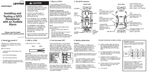
Installing and Testing a GFCIReceptacle with an AudibleAlarmPlease read this leaflet completely before getting started.1. What is a GFCI?A GFCI receptacle is different fromconventional receptacles. In the event of aground fault, a GFCI will trip and quickly stopthe flow of electricity to prevent serious injury.Definition of a ground fault:Instead of following its normal safe path,electricity passes through a person's body toreach the ground. For example, a defectiveappliance can cause a ground fault.A GFCI receptacle does NOT protect againstcircuit overloads, short circuits, or shocks. Forexample, you can still be shocked if you touchbare wires while standing on a non-conductingsurface, such as a wood floor.NOTE:GFCI's contain a lockout feature that willprevent RESET if:• T here is no power being supplied tothe GFCI.• T he GFCI is miswired due to reversal ofthe LINE and LOAD leads.• T he GFCI cannot pass its internal test,indicating that it may not be able to provideprotection in the event of a ground fault.2. The GFCI's features3. Should you install it?Installing a GFCI receptacle can be more complicated than installing a conventional receptacle.Make sure that you:• U nderstand basic wiring principles and techniques• Can interpret wiring diagrams• Have circuit wiring experience• A re prepared to take a few minutes to test your work, making sure that you have wired the GFCI receptacle correctly 4. LINE vs. LOADA cable consists of 2 or 3 wires.Cable WiresLINE cable:Delivers power from the service panel (breakerpanel or fuse box) to the GFCI. If there is onlyone cable entering the electrical box, it is theLINE cable. This cable should be connected tothe GFCI's LINE terminals only.LOAD cable:Delivers power from the GFCI to anotherreceptacle in the circuit. This cable should beconnected to the GFCI's LOAD terminals only.The LOAD terminals are under the yellowsticker. Do NOTremove the sticker at this time.5. Turn the power OFFPlug an electrical device, such as a lamp orradio, into the receptacle on which you areworking. Turn the lamp or radio ON. Then, goto the service panel. Find the breaker or fusethat protects that receptacle. Place the breakerin the OFF position or completely remove thefuse. The lamp or radio must turn OFF.Next, plug in and turn ON the lamp or radio atthe receptacle's other outlet to make sure thepower is OFF at both outlets. If the power is notOFF, stop work and call an electrician tocomplete the installation.6. Identify cables/wiresImportant:DO NOT install the GFCI receptacle in anelectrical box containing (a) more than four (4)wires (not including the grounding wires) or(b) cables with more than two (2) wires (notincluding the grounding wire). Contact aqualified electrician if either (a) or (b) are true.If you are replacing an old receptacle, pull it outof the electrical box without disconnecting thewires.• I f you see one cable (2-3 wires), it is theLINE cable. The receptacle is probably inposition C (see diagram to the right).Remove the receptacle and go to step 7A.• I f you see two cables (4-6 wires), thereceptacle is probably in position A or B(see diagram to the right). Follow steps a-eof the procedure to the right.Procedure: box with two (2) cables (4-6 wires):(a) D etach one cable's white wire and hotwires from the receptacle and cap eachone separately with a wire connector.Make sure that they are from the samecable.(b) R e-install the receptacle in the electricalbox, attach faceplate, then turn the powerON at the service panel.(c) D etermine if power is flowing to thereceptacle. If so, the capped wires are theLOAD wires. If not, the capped wires arethe LINE wires.(d) T urn the power OFF at the service panel,label the LINE and LOAD wires, thenremove the receptacle.(e) Go to step 7B.PK-A3105-10-00-2AFRONT VIEWOutletTESTLEDClipOutletBACK VIEWGrounding Terminal (Green):Connection for barecopper or green wireLINEWhite terminal (Silver):Connection for the LINEcable's white wireLOADWhite terminal (Silver):Connection for the LOADcable's white wireLINEcable's black wireA yellow stickerthis time.LOADcable's black wireScrew (terminal) colors:Green = grounding terminalSilver = WHITE terminalsBrass or Black = HOT terminalsProcedure:(a) T his GFCI is shipped from the factory in the tripped condition and cannot be reset until it is wired correctlyand power is supplied to the device. Plug a lamp or radio into the GFCI (and leave it plugged in). Turn the power ON at the service panel. Ensure that the GFCI is still in the tripped condition by pressing the TEST button. The GFCI should be emitting an audible alert and the LED indicator should be OFF.(b) P ress the RESET button fully. If the lamp or radio turns ON, the audible alert turns OFF, and theLED indicator is ON, the GFCI has been installed correctly. If the GFCI cannot be reset, go to the Troubleshooting section.(c) I f you installed your GFCI using step 7B press the TEST button, then plug a lamp or radio intosurrounding receptacles to see which one(s), in addition to the GFCI, lost power when you pressed the TEST button. DO NOT plug life saving devices into any of the receptacles that lost power. Place a "GFCI PROTECTED OUTLET" sticker on every receptacle that lost power, then press the RESET button to reset the GFCI.(d) P ress the TEST button (then RESET button) every month to assure proper operation. If the GFCIcannot be reset, then it must be replaced.(e) T o turn off audible alert when GFCI cannot be reset: press and hold the RESET button fully for 3seconds to stop the audible alert and then contact Leviton Customer Service or your local electrician.SELF-TEST OPERATION• A Self-Test GFCI receptacle has all the features of a conventional GFCI receptacle. In addition, this receptacle tests itself periodically to confirm the GFCI electronics are functional. The Status Indicator Light will be solid green when the GFCI is powered from Line side and working correctly.• S elf-Test Indications: If the Status Indicator Light is solid or flashing RED a problem may exist. Press the TEST button to trip the GFCI. If unable to Reset, replace the GFCI. NOTE: The status indicator may flash Red at power "ON" and Reset.TROUBLESHOOTINGTurn the power OFF and check the wire connections against the appropriate wiring diagram in step 7A or 7B. Make sure that there are no loose wires or loose connections. If the Status Indicator Light is not ON and the device is unable to reset this could be a result of no power available. Start the test from the beginning of step 8 if you rewired any connections to the GFCI.PK-A3105-10-00-2A© 2015 Leviton Mfg. Co., Inc.FOR CANADA ONLYFor warranty information and/or product returns, residents of Canada should contact Leviton in writing at Leviton Manufacturing of Canada Ltd to the attention of the Quality Assurance Department, 165 Hymus Blvd, Pointe-Claire (Quebec), Canada H9R 1E9 or by telephone at 1 800 405-5320.SmartlockPro is a Trademark of Leviton Manufacturing Co., Inc. registered in the United States, Canada, Mexico and China.For Technical Assistance Call: 1-800-824-3005 (U.S.A. Only)1 800 405-5320 (Canada Only) LIMITED 2 YEAR WARRANTY AND EXCLUSIONSLeviton warrants to the original consumer purchaser and not for the benefit of anyone else that this product at the time of its sale by Leviton is free of defects in materials and workmanship under normal and proper use for two years from the purchase date. Leviton’s only obligation is to correct such defects by repair or replacement, at its option. For details visit or call 1-800-824-3005. This warranty excludes and there is disclaimed liability for labor for removal of this product or reinstallation. This warranty is void if this product is installed improperly or in an improper environment, overloaded, misused, opened, abused, or altered in any manner, or is not used under normal operating conditions or not in accordance with any labels or instructions. There are no other or implied warranties of any kind, including merchantability and fitness for a particular purpose , but if any implied warranty is required by the applicable jurisdiction, the duration of any such implied warranty, including merchantability and fitness for a particular purpose, is limited to two years. Leviton is not liable for incidental, indirect, special, or consequential damages, including without limitation, damage to, or loss of use of, any equipment, lost sales or profits or delay or failure to perform this warranty obligation . The remedies provided herein are the exclusive remedies under this warranty, whether based on contract, tort or otherwise.FCC STATEMENTThis equipment has been tested and found to comply with the limits for a Class B digital device, pursuant to part 15 of the FCC Rules. These limits are designed to provide reasonable protection against harmful interference in a residential installation. This equipment generates, uses and can radiate radio frequency energy and, if not installed and used in accordance with the instructions, may cause harmful interference to radio communications. However, there is no guarantee that interference will not occur in a particular installation. If this equipment does cause harmful interference to radio or television reception, which can be determined by turning the equipment off and on, the user is encouraged to try to correct the interference by one or more of the following measures:• Reorient or relocate the receiving antenna.• Increase the separation between the equipment and receiver.• Connect the equipment into an outlet on a circuit different from that to which the receiver is connected.• Consult the dealer or an experienced radio/TV technician for help.IC STATEMENTThis device complies with Industry Canada licence-exempt RSS standard(s). Operation is subject to the following two conditions: (1) this device may not cause interference, and (2) this device must accept any interference, including interference that may cause undesired operation of the device.This product is covered by U.S. Patent Nos. 6,040,967; 6,246,558; 6,282,070; 6,381,112; 6,437,953; 6,646,838; 6,657,834; 6,788,173; 6,864,766; 6,944,001; 7,336,458; 7,355,117; 7,400,479; 7,463,124; 7,697,252; 7,737,809; 7,764,151; 7,820,909; 7,868,719*; 7,907,371; 8,004,804; 8,054,595; 8,130,480; 8,242,362; 8,547,126, 8,587,914; 8,599,522; 8,944,859 and corresponding foreign patents (*applies only to Cat. No. GFTA2).。
星鱼智能插座用户手册说明书
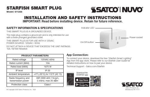
SAFETY INFORMATION & SPECIFICATIONSTHIS SMART PLUG IS A GROUNDED DEVICE.The male plug contains a ground pin and is only intended for use with a three-pronged grounded outlet.THIS SMART PLUG IS FOR USE WITH A 125VAC POWER SOURCE: 125VAC / 60HzDO NOT ATTACH A DEVICE THAT EXCEEDS THE UNIT RATINGS: 15A /1875W ResistiveApp Connection:To connect your device, download the free “Starfish Smart Lighting” App from the app store. Please refer to our Starfish User Guide for detailed instructions on how to pair your device.Technical Support - /StarfishSTARFISH SMART PLUGModel: S11266Satco Products, Inc.INSTALLATION AND SAFETY INSTRUCTIONSIMPORTANT: Read before installing device. Retain for future reference.Indicator LEDPower socketOn/Off buttonDownload theSTARFISH appPRODUCT PARAMETERSRated voltage 125VAC 60HzRated current (MAX)15A Rated load (MAX)1875 W IP levelIP 20Ambient temperature -4°F (-20°C) to 113°F (45 °C)Radio frequency and transmission power WiFi IEEE 802.11b/g/n, 2.4GHz, max 20 dBmProtection classClass IWARNINGDo not insert smart plug into another smart plug.The power is disconnected only when the smart plug is removedfrom an electrical outlet.The smart plug should be placed near the appliance and easily accessible to user.Do not open the product.Prior to using, ensure the smart plug is not damaged.Do not install the plug into a socket if the plug casing is damaged in any way. Please take the Technical Data (in particular the maximum permissible switching capacity of the relay and the type of load to be connected) into account before connecting a load!All load data relates to resistive loads! Do not exceed the capacity specified for the device. Exceeding this capacity could lead to the destruction of the device, to a fire or to an electrical accident, and, the reliable switching o of a controlled device may no longer be possible.Do not connect any appliances which could cause fire or otherdamage if switched on inadvertently (e.g. irons, power tools).Do not use plugs to disconnect appliances from the main power supply of the home. The load is not galvanically isolated from the main power supply. For indoor use only.Do not use this product near water for example near a bath tub wash bowl, kitchen sink or laundry tub, in a wet basement or near a swimming pool. MAINTENANCE AND CAREThe product is maintenance-free. Repairs should only be performed by qualified persons. Clean the product with a soft clean, dry and lint-free cloth after removing the plug from the electrical outlet . Do not use cleaning agents containing solvents.Incorrect handling or non-observance of safety warnings may compromise the protection afforded by the device.CAUTIONThis device complies with Part 15 0f the FCC Rules and Industry Canada license-exempt RSS standard(s). Operation is subject to the following two conditions: (1) this device may not cause harmful interference. and (2) this device must accept any interference received. including interference that may cause undesired operation.Changes or modifications not expressly approved by the party responsible for compliance could void the user’s authority to operate the equipment.This equipment has been tested and found to comply with the limits for a Class B digital device. pursuant to part 15 0f the FCC Rules. These limits are designed to provide reasonable protection against harmful interference in a residential installation. This equipment generates uses and can radiate radio frequency energy and. if not installed and used in accordance withthe instructions. may cause harmful interference to radio communications. However. there is no guarantee that interference will not occur in a particular installation. If this equipment does cause harmful interference to radio or television reception, which can be determined by turning the equipment o and on. the user is encouraged to try to correct the interference by one or more of the following measures:—Reorient or relocate the receiving antenna.—Increase the separation between the equipment and receiver.— C onnect the equipment into an outlet on a circuit different from thatto which the receiver is connected.—Consult the dealer or an experienced radio/TV technician for help.CAN ICES-3 (B)/NMB-3(B)To satisfy FCC / lC RF exposure requirements. a separation distance of 20 cm or more should be maintained between the antenna of this device and persons during device operation. To ensure compliance. operations at closer than this distance is not recommended.Satco Products, Inc.。
Qubino Flush 2 Relay Z-Wave 智能插座说明书
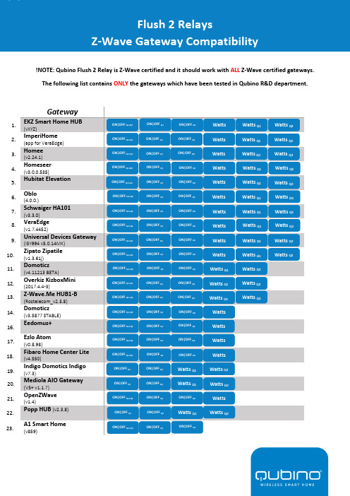
!NOTE: Qubino Flush 2 Relay is Z-Wave certified and it should work with ALL Z-Wave certified gateways. The following list contains ONLY the gateways which have been tested in Qubino R&D department.GatewayEKZ Smart Home HUB (vXYZ)ImperiHome (app for VeraEdge) Homee (v2.24.1)Homeseer (v3.0.0.535)Hubitat Elevation Oblo(4.0.0.)Schwaiger HA101(v3.3.0) VeraEdge (v1.7.4452)Universal Devices Gateway (ISY994 v5.0.14MK)Zipato Zipatile (v1.3.61j) Domoticz (v4.11213 BETA)Overkiz KizboxMini (2017.4.4-3)Z-Wave.Me HUB1-B (Rostelecom_v2.3.8)Domoticz (v3.5877 STABLE) Eedomus+Ezlo Atom (v0.8.98)Fibaro Home Center Lite (v4.550)Indigo Domotics Indigo (v7.3)Mediola AIO Gateway (V5+ v1.1.7) OpenZWave (v1.4)Popp HUB (v2.3.8) A1 Smart Home (v859)Flush 2 RelaysZ-Wave Gateway Compatibility2. 3. 1.5. 4. 7. 6. 9.8. 16. 11. 10. 14. 13. 12.17. 18. 19. 15.22. 21. 20. 23. ON|OFF Q1+Q2 ON|OFF Q1 ON|OFF Q2Watts Watts Q1 Watts Q2 ON|OFF Q1+Q2 ON|OFF Q1 ON|OFF Q2Watts Watts Q1 Watts Q2ON|OFF Q1+Q2 ON|OFF Q1ON|OFF Q2Watts Watts Q1 Watts Q2ON|OFF Q1+Q2 ON|OFF Q1 ON|OFF Q2Watts Watts Q1 Watts Q2 ON|OFF Q1+Q2ON|OFF Q1 ON|OFF Q2Watts Watts Q2Watts Q1 ON|OFF Q1+Q2 ON|OFF Q1 ON|OFF Q2Watts Watts Q1Watts Q2ON|OFF Q1+Q2 ON|OFF Q1 ON|OFF Q2Watts Watts Q1 Watts Q2ON|OFF Q1+Q2 ON|OFF Q1 ON|OFF Q2Watts Watts Q1 Watts Q2ON|OFF Q1+Q2 ON|OFF Q1 ON|OFF Q2Watts Watts Q2Watts Q1 ON|OFF Q1+Q2 ON|OFF Q1 ON|OFF Q2Watts Q2 Watts Q1 ON|OFF Q1+Q2 ON|OFF Q1 ON|OFF Q2 Watts ON|OFF Q1+Q2 ON|OFF Q1 ON|OFF Q2Watts ON|OFF Q1+Q2 ON|OFF Q1 ON|OFF Q2Watts ON|OFF Q1 ON|OFF Q2Watts Q1 Watts Q2 ON|OFF Q1 ON|OFF Q2Watts Q1Watts Q2 ON|OFF Q1+Q2 ON|OFF Q1ON|OFF Q2Watts ON|OFF Q1 ON|OFF Q2Watts Q1Watts Q2ON|OFF Q1+Q2 ON|OFF Q1ON|OFF Q2ON|OFF Q1+Q2ON|OFF Q1ON|OFF Q2Watts ON|OFF Q1+Q2 ON|OFF Q1 ON|OFF Q2Watts Q1 Watts Q2 ON|OFF Q1+Q2 ON|OFF Q1 ON|OFF Q2Watts Q1 Watts Q223. 21. 22. ON|OFF Q1+Q2ON|OFF Q1ON|OFF Q2Watts Watts Q1 Watts Q2Athom Homey(v2.5.2)Bosch IoT Gateway Soft (v9.2 zw5.0.5) Devolo (v8.84.1) FHEM (v5.9)Home Assistant (v0.97.2)Icontrol Networks Piper (v2.3.8 nv) Jeedom OpenHAB 2(v2.4.0 STABLE)ZwaveMe (v3.0.0)Zipato Zipabox (v1.3.24)Samsung SmartThings (v000.021.00012)Samsung SmartThings (v000.021.00012 3rd party)24. 25. 26. 27. 29. 28.30. 31. 32. 33. ON|OFF Q1 ON|OFF Q2 Watts Q2ON|OFF Q1+Q2 ON|OFF Q1ON|OFF Q1+Q2ON|OFF Q1+Q2 ON|OFF Q1+Q2 ON|OFF Q1 ON|OFF Q2ON|OFF Q1+Q2 ON|OFF Q1 ON|OFF Q2ON|OFF Q1+Q2 ON|OFF Q1 ON|OFF Q2ON|OFF Q1+Q2 ON|OFF Q1 ON|OFF Q2ON|OFF Q1+Q2 ON|OFF Q1 ON|OFF Q2ON|OFF Q1+Q2 ON|OFF Q1 ON|OFF Q2ON|OFF Q1+Q2 ON|OFF Q1 ON|OFF Q2ON|OFF Q1+Q2ON|OFF Q1ON|OFF Q234. 35.。
WL美标墙面插座英文说明书
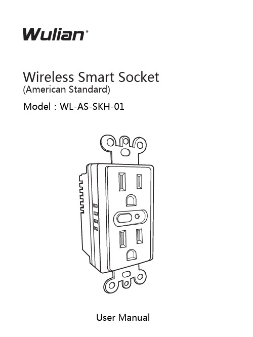
Wireless Smart Socket (American Standard)M odel:WL-AS-SKH-01Thank you for choosing Wulian. Installation guide is specially for you to know the installation steps and functions of Wulian products.This manual is protected under international copyright law. Without the prior written permission of Nanjing IOT Sensor Technology Co., Ltd., any part of this manual are not allowed to copy, distribute, translate or transfer in any form or by any means (electronic version or mechanical version), including copies, the data recorded or stored in any information storage or retrieval system, and reverse engineering is prohibited.IOT Sensor, Wulian are all registered trademarks of Nanjing IOT Sensor Technology Co., Ltd. Nanjing IOT Sensor Technology Co., Ltd. owns all above trademark. Usage of these trademarks is strictly prohibited without the written authorization and permission from Wulian. Legal action will be taken against unauthorized usage of these trademarks.All the other trademarks and copyrights in this manual belong to respective possessor.Wulian reserves the right to change and modify misprinted and incorrect information and improves programs or devices at any time without notice. Such modifications will be written in the new-edition of the manual.Nanjing IOT Sensor Technology Co., Ltd.Publication No.: 2013-0318.V2Ⅰ.Product IntroductionⅡ.Function FeaturesWL-AS-SKH-01 Wireless Smart Socket(American Standard) , based on ZigBee technology. allows users to control remotely by any smart mobile terminals and wireless network or local control. It confirms to IEEE802.15.4 ZigBee/SmartRoom HA protocol standard, and can be used in any ZigBee/SmartRoom HA protocol network.This product is also widely applied in smart building,smart hospital, smart hotel, and smart breeding etc besides the smart home system Support ZigBee protocolZigBee device type :RepeaterCute appearanceSimple installation, easy operationⅢ.Function illustrationAlways in power on plug and playIV .Installation Steps1.Connect this product with the wire of the wall box,Green Line into Earth LineNote: Please make sure that the power has been turned off before installation!(Green Line inserted)(Black Line inserts)(White Line inserted)Null Line2.Embed the screws in the wall box into mounting holes and tighten.Make sure the indication light upward direction.3. Shut down the decorative cover for the final installation.Ⅴ. Application methodsworking Setup(1)Please make sure the gateway (need to additional purchase) ZigBee network is working with power within the valid communication distance of gateway before configuring the wall switch.Note: For more details please refer to wireless gateway instructionWireless GatewayTablet Cell Phone Wulian Smart Socket(American Standard)(2)Quickly click Open Key 4 times to join ZigBee network. LED Indicator Light stays flickering when searching network. Upon successful connection, LED Indicator Light will stay lit in 2 seconds and then goes off.(3)ZigBee network.LED indicator goes out after flashing 4 times.2.Software download(1)Choose the related software according to different smart mobile terminal.a) Android users can search for the term“wulian” in Google Play Store,select “Wulian Smart Home” for downloading;b) iPhone and iPad users can log into APP Store and search for theterm“Wulian”, select “Wulian Smart Home”for downloading;c) Users can also directly download from our official website/english/(2) Install and operate according to the indication of each version of software;(3)Installation completed, enter setup and usage interface(4) It also supports computer operation according to users’ needs.3. How to use(1) Please install and operate according to the software(2) For specific operations, please refer to the application method of eachversion.(3) In normal condition,this product can convey 960W, Max 1800W.Through various smart mobile terminals, the users can control remotely and knowⅥ.NotesInstallationIf you are new to using it, please read this product instruction carefully before installation.CleaningThis product should be installed in a clean and dry place to avoid humidity or other material entering internal components which will influence its work. When the surface is stained with dust, dry it with soft cloth, cleaning fluid with corrosive composition and other chemical solvent are forbidden.StorageThose products packed in boxes should be placed in the location which is dry, free of corrosive gas and available to air. The height of pile should be no more than 10 layers. Store temperature should be between -10℃~+ 40℃ with humidity ≤75%.TransportationThose products packed in boxes can be transported with any kind of means, if the direct influence of rain, snow, and severe impact is avoided.After-sale serviceOnce broken, it should be send to the local maintenance station and only professional personnel can open it. Our customer service department is also available for help.Service Hotline 400-928-9228.Ⅶ.Product Standard Ⅷ. Components within the packageCommunication WayPowerLoad capacityWorking TemperatureWeightNet Weight IEEE802.15.4(ZigBee )120V AC ,60Hz Max1800W -10℃~+45℃120g 70gComponentsQTY Wireless Smart SocketManualWarranty Card 111Ⅸ.Ordering InformationArt.No Model WLPN1312310WL-ZSKWNPW-W3140-01Building No. 11, Software Valley,No. 15, Fengji Avenue, Yuhuatai District, Nanjing. Zip code: 210039Service Hotline: 400-928-9228。
品益智能插座说明书
品益智能插座说明书
一、产品介绍
本产品采用国际先进的数字RF技术,性能稳定;具有非常稳定的记忆储存功能;在有WIFI情况下与手机的APP配合使用,可远程操作控制;并适配多
国插头:国标,英标,美标等。
使用本产品不仅能给用户的生活带来诸多便利,还能保护电器,消除待机功耗,节约电资源。
二、操作说明
智能插座上电后,LED指示灯亮红灯,表示智能插座处于断电状态;通过
短按智能插座上的开关键,可以控制智能插座在通电状态与断电状态之间相互
转换。
此时,短按下智能插座上的开关键,LED指示灯由红灯闪烁变为蓝灯闪烁,表示智能插座处于通电状态。
注意:智能插座重新上电,初始状态都是断电状态。