berger测试机简易培训
Berger测试仪培训资料.
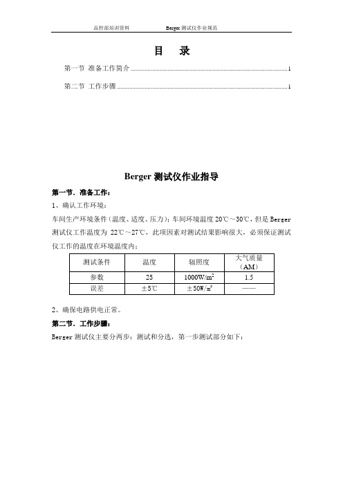
目录第一节准备工作简介 (1)第二节工作步骤 (1)Berger测试仪作业指导第一节.准备工作:1、确认工作环境:车间生产环境条件(温度、适度、压力);车间环境温度20℃~30℃,但是Berger 测试仪工作温度为22℃~27℃,此项因素对测试结果影响很大,必须保证测试仪工作的温度在环境温度内;测试条件温度辐照度大气质量(AM)参数251000W/m2 1.5误差±5℃±50W/m2 ——2、确保电路供电正常。
第二节.工作步骤:Berger测试仪主要分两步:测试和分选,第一步测试部分如下:㈠.测试部分1.进入软件界面在电脑桌面上双击Scload软件图标,如右图。
2.进入Scload软件主界面如右图所示。
3.各个菜单简介,如右图。
①菜单栏File、view、Graph、Measurements、Auto Mode、Settings,分别对应文件:视图、图表、测量、自动模式、设置。
②快捷栏分别是新建、打开、保存、预览、打印、图标选择、参数设置、手动调试、手动测试、自动测试。
③界面测试类型。
菜单栏快捷栏④电性能参数如右图。
4.片盒分布图各个参数具体如图。
电性能参数T 测试温度Uoc 开路电压E 测试光强Isc 短路电流Pmpp最大输出功率FF 填充因子Umpp 最大工作电压Rs 串联电阻Impp 最大工作电流Rsh 并联电阻Eff 转换效率Irev1 反向漏电电流(加10v反偏电压时)Irev2反向漏电电流(加12v反偏电压时)㈡.进入自动工作模式1.在菜单Settings 下的Classification中的Open中选择测试程序,如右图。
2.选择测试数据保存路径。
在Settings中选择Configuration;选择程序选择数据保存路径3.然后在弹出的对话框中选择Database,点击Browse选择保存路径。
(需注意选择的数据库文件必须是复制系统开的,不得自己新建)进入自动模式4.以上操作完成后,需转入自动测试模式时,应点击“快捷栏”红色自动测试按弹出MeasurementParameters 栏框,并进行修改为当天生产的时期然后再确认生产中的测试电池片型号是否与实物电池片型号相符合。
4太阳能电池测试分选工序介绍

4太阳能电池测试分选工序介绍对于制作太阳能电池而言,印刷烧结后的电池片已经算是完成了电池片的制作过程,但是怎么去分辨太阳能电池的好坏,这就要用到我们的测试以及分选工序。
测试工序是按照效率等电参数的标准对太阳能电池片进行选择,只有符合要求的电池片才能够用力进行组件的制作。
分选是按照太阳能电池片的外观标准对太阳能电池片进行选择,只有符合客户要求才是合格的电池片。
下面我们针对我们使用的Berger测试机对这两个工序进行一下介绍:一、太阳能电池片的测试1.测试机的构成一般情况下,测试机由三个部分构成:上片单元、测试系统单元、分档单元,分别如下图所示。
图1:测试机构成在测试机中,测试系统单元是测试机的核心部位,针对测试系统单元我们进行一下重点的介绍:光源标准太阳能电池待测试太阳能电池PSS模拟负载电脑市电图2:测试系统单元构成图3:测试机探针图2.Berger测试系统的原理:测试系统的原理是通过模拟1.5AM1000W/cm2太阳光脉冲照射PV电池表面产生光电流,光电流流过可编程式模拟负载,在负载两端产生电压,负载装置将采样到的电流、电压、标准片检测到的光强以及感温装置检测到的环境温度值,通过RS232接口传送给监控软件进行计算和修正,得到PV电池的各种指标和曲线、然后根据结果进行分类和结果输出。
测试的原理图如:图4所示:其中PV为待测电池片,V为电压测量装置,I为电流测量装置,RL为可编程式模拟负载,它的值可在0.003-400Ω之间变化。
图4:Beger测试系统测试原理图3.太阳能电池标准测试前提介绍在太阳能电池的标准测试中,有三个前提因素,即标准太阳光谱为AM1.5,温度为25℃,光强为1000W/M2。
当测试数据不是在这个范围时,所测得的数据都是不准确的。
下面我们针对这几个前提得到含义以及影响分别介绍一下:所谓光谱为AM1.5,即指的是1.5个大气质量。
大气质量被定义为光穿过大气的路径长度,长度最短时的路径(即当太阳处在头顶正上方时)规定为“一个标准大气质量”。
Berger测试的介绍
VOC
Rs & Rsh
RSH ISC The slopes of these lines are characteristic resistances. RS
13
VOC
等效电路图
14
Cell RS
ISC
RSH
RLOAD
Cell
IV曲线分为五个部分共110个点组成.
15
三.测试设备的校准
1.只能使用一级标准组件校准,校准时测试数据与标称数据的要求: Isc <±1% Pmpp <±1%
17
二级标准组件的使用
1.如果在日常的检验过程中,测试数据与标称数据在控制的范围之内: Isc <±1% Pmpp <校准. 2.如果测试数据在范围之外,有必要先检验以下几个参数:
18
Isc异常: Monitor cell 上是否有灰尘. 检查窗帘是否有异样,是否更换过. 二级标准组件是否衰减过多. Voc异常: 温度探测仪器是否损坏或者不准确. 光强是否超出范围了(reference voltage是否为85%-95%) FF异常: 连接器或者连接线是否损坏. 光前的均匀性是否有问题. 排除以上原因,如果测试值还是在范围之外,通知相关人员是否有必要再次使 用一级标准组件校准. 以下几种情况下建议校准: 1.更换monitor cell 2.更换灯管
3.更换其他硬件(PSL PSS)
19
建立不同的monitor cell 类型
不同组件类型在更换的时候避免再次使用一级标准组件校准,可以通 过新建不同的monitor cell类型以对应不同的组件类型. 步骤:
1.进入管理员模式 SettingsOperating Mode
2.Mearusement Edit Monitor cells copy 并输入相应的参数. 3.按 F5 进入测试界面,Monitor 里面选择刚相应的monitor cell 类型.
赫爽测试仪培训资料

一、启动软硬件
1 2 3 4 5 、现场电源:电压范围,220V左右,并确认接地线。 、确认模拟器、测试柜、工控机柜包装,外壳,内部电路板外观以及插线头无问题。 、硬件连接,固定好。 、启动工控机,打开软件。 、启动模拟器和电子负载,并确认在联机状态(关闭时,先关闭模拟器和电子负载,再 关闭工控机。注意:关闭模拟器时,请先放电至几十伏内。)
三、模拟器校正
校正过程参见模拟器校正步骤。 注意事项:测试标改 温度系数,再进行第二步和第三步,当然,也可直接修改电流或电压校正系数,不过 此时短路电流或开路电压会有偏差。
四、测试及文件保存
1.测试:生产中,快捷的测试有按键盘空格键、按遥控器、触发开关等 2.文件保存:“自动保存” 、扫描枪、点击“保存当前文件”和点击“保存所有文件” 四种保存途径。
两种操作权限(见图九)
模拟器校正分三步: 第一步充电电压系数:
计算机联机 的状态下, 按下“开始” 按键,可以 再PLG前面 板上看到充 电电压数值, 待其充电完 成稳定后, 将其值填入 下图编辑框, 然后接受以 上充电电压 系数。
第二步光强:
输入充电电压,按下开始充电; 红灯表示充电完成后,按下“光 强测试”。
模拟器校正说明: 1.第一步充电电压系数只需在设备第一次使用的 情况下进行,校正好后无需改动。 2.第二步光强在 PLG充电电压发生改变的情况下, 页就是模拟器的光强发生改变的情况下,需要进 行光强的测试,软件自动保存测试结果。 3.第三步电流电压系数松开架子测试计算工控机 与电子负载的电压比例,测试好后此结果也不需 要经常改变,保存其固定值;需要经常校正的是 电流调整系数和电压调整系数,对于不同的电池 组件,可能需要不同的标准组件来进行校正,所 以应当根据需要进行电压电流校正,这一步可能 会经常用到
安博格培训课件(1)

轨道模拟调整分析
一、基本思路 二、符号法则 内 三、调整方法 容 四、调整结果评价与处理 提 五、软件其他功能
纲
一、基本思路
1.1 、首先明确基准轨:平面位置以高轨(外轨)为基 准,高程以低轨(内轨)为基准,直线区间上的基准 轨参考大里程方向的曲线;
2.2、在 GRP Slabrep 生成的报表中,导向轨为“-1” 表示右手曲线,平面位置以左轨(高轨)为基准,高 程以右轨(低轨)为基准;导向轨为“1”表示左手曲 线,平面位置以右轨(高轨)为基准,高程以左轨 (低轨)为基准;
测量过程中,要随时观察电子气泡,L、T轴偏差值不 得大于0.0010,否则测量值误差会较大。
2.6、设站技术标准
a)全站仪采用后方交会的方法进行设站,为了确保 全站仪的设站精度,使用8个后视点(全站仪前 后各2对),如果现场条件不满足,至少应使用6 个控制点。
2.6、设站技术标准
b)设站中误差:东坐标/北坐标/高程0.7mm、水平 定向 2″以内,误差越小测量精确度越好(建议 水平定向控制在1.4″以内)。注:连续桥、特 殊孔跨桥自由设站点精度可放宽至1.0mm。
2.5、测量设站
2.5、测量设站
C)按“继续”进行测量目标界面,依次从点号中选择 CPⅢ点后按“ALL”测量。 技巧:按照从大到小的顺序依次手工瞄准两个CPⅢ点 后,其它CPⅢ点全站仪会自动照准。 注意:夜间特别是测量第一、二个CPⅢ点时,先按“ 测距”,待测距稳定后再按“ALL”测量,可以精确 对准棱镜,减少瞄准误差。
f) 现场应做好设站记录工作。
三、小车校准
• 每次上道作业前都须对小车进行斜率校准(水 平校正)
三、小车校准
校准步骤: A)将小车反向于测量方向放置于轨道上; B)打开测量文件-设置,点击斜率校准向导按钮(最下
Berger 培训

2
一、软件界面 打开桌面SCLoad_STD快捷方式,如下图所示:
电流—电压 曲线显示框
电性能数据
批号、日期、 分档等信息 输入
各分档Bin数 量显示
2
3
二、基本参数设定 点击菜单栏中Measurement→edit cell types…,出现如下所示对 话框:
图2.1
19
20
20
(2)校准开压异常: 校准步骤正常,但开压明显偏低,导致效率相差较大。点击Setting → Configuration进入以下界面:
图5.3
18
19
测试温度的获得一般有两种:Intrare和PT100。 Temperature acquisition for automatic operation:自动操作时获得温度。 Temperature acquisition for manual operation:手动操作时获得温度。 自动操作模式用于生产,手动操作用于校准。 一般情况是:自动模式选择Infrare,手动模式选择PT100。当开压 较低时,可以通过将手动模式PT100改选Infrared的方式来调节。
点击Edit按钮,出现如图2.2界面
3
4
图2.2
4
5
Name:电池片类型; Cell area:电池片面积; Temperature correction:温度系数; Cell current:单位面积电流; Operating point voltage:电压选定点,一般设定0.5V。 Dark current operating point:设定反向电压,算出暗电流大小。一般 为-6V或者-12V。
图3.6
10
Josef Berger
vorgelegt von Josef Berger am 11. Januar 2002
Erstgutachter: Zweitgutachter:
Prof. H. Osswald Prof. M. Wolff (Universit¨ at T¨ ubingen)
Tag des Rigorosums: 22.07.2002
2 The Orthogonal Projection from L2 W (µ, H) onto LA (µ, H) . . . . 39
The Stochastic Integral . . . . . . . . . . . . . . . . . . . . . . . . . . . . . . . . . . . . . . . . . 45 The Skorohod Integral . . . . . . . . . . . . . . . . . . . . . . . . . . . . . . . . . . . . . . . . . . 49 The Malliavin Derivative . . . . . . . . . . . . . . . . . . . . . . . . . . . . . . . . . . . . . . . 55 Representation of Martingales . . . . . . . . . . . . . . . . . . . . . . . . . . . . . . . . . 57 The Clark Ocone Formula . . . . . . . . . . . . . . . . . . . . . . . . . . . . . . . . . . . . . . 63 Reference to Abstract Wiener Spaces . . . . . . . . . . . . . . . . . . . . . . . . .65 Appendix: an Internal Representation of the L´ evy Transformation of Brownian Motion . . . . . . . . . . . . . . . . . . . . . . . . . . 73
贝尔德直读光谱仪培训题材

贝尔德直读光谱仪培训题材一. 光电直读光谱分析的应用近况及新发展DV4-1000型光电直读光谱仪,1964年美国贝尔德公司开始生产光谱仪持续生产了DV2、DV4、DV6,从70年代进入中国,直读其实就是直观可见数据的意思。
现在市专场上的光谱有德国的OBLF、斯派克,美国的ARL,国产的瑞利(但国产的缺点是高合金钢和极低含分析误差大)。
DV4-1000中1000是指焦距,曲率半径为1000mm的凹球面镜,光源:KH-3/5 型,重复频率100周(现在新产光源都在400周以上),频率低的缺陷:峰压不稳定,随交流供电的电压和频率的波动造成分析数据的漂移,严重影响分析的精度和准确度。
二. 光电光谱分析的原理.(光谱光室分布图)试样经过激发时,不同元素的原子,在火焰、电弧、火花等光源激发下,由于原子能级跃迁发射出特有的谱线,即“特征谱线”,能通过入射光学系统到光栅上,光栅将光分解成光谱,这些光谱线代表样品中的各个元素,各元素光谱线的强度与样品中元素的含量成比例,每一元素至少有一条光谱线通过出口狭缝,射到光电倍增管的光阴极上,当元素的浓度变化时光谱线的强度也变化,光电倍增管的输出电流也随之变化,除了元素光谱线以外,用一条或更多的光谱线作为内标线它将与元素线相比,通过测量板将从元素电容器送来的模拟分析数据转换成数字信号,然后计算机进行计算元素的含量。
三. 光电光谱的光学系统及光转换1 / 121.罗兰圆(270个出射狭缝),凹面光栅光学系统(其实与我们的光盘CD相适),主要起到光谱线的分散和折射。
使各元素的谱线分别射信对应的光电倍增管的光阴上。
2.光电倍增管的光电转换(能将光谱线射至光阴上产生的光电,放大到几百万倍,以达到测量系统所要求的电流值,此电流可通过同轴电缆送到元素板上进行换算。
)四.用好光电光谱仪的操作要点及注意事项1..光谱仪的外围条件1).仪器的周围不应有振动,不受阳光的直接照射,散热(风扇),机房温度控制在23 ±2℃,温度(有除湿器,<60,不然会引起一些电器元件短路烧坏),应有良好的地线越小越好,接地电阻<4。
BERGER光强校准测试作业指导书
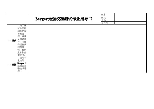
版本版次Berger光强校准测试作业指导书页码文件号一:目的:为了规范分类检测机光强校准过程,以满足测试条件,同时保证测试的准确性,特制定本作业指导书.二:范围:适用于电池线Berger分选设备光强校准过程.三:确认:确认时机,每班上班前确认,每两小时确认一次,确认的间隔误差不得超过20分钟.四:校验前准备I:校准前分类检测机测试过程检查;II:校准前台面检查;1:T为温度,其温度范围为25±2℃,E为幅照,其幅照强度范围在1000±50W/m2 1:检查探针是否有倾斜,损坏现象.2:Voc为所测电池片的开路电压,一般在0.60V-0.62V, Isc为短路电流,一般 2:二级标片使用前检查是否完好,是否在有效期内,如果不不低于5.0A.在有效期内及时更换.3:Rs为所测电池片的串联电阻,一般在0.004-0.008欧,Rsh为所测电池片的并 3:校准操作之前先检查一下探针与电池片接触是否良好,光联电阻,一般大于10欧.强幅照标片上面有无异物遮盖.4:FF为所测电池片的填充因子,一般在75%-77%.版本版次Berger光强校准测试作业指导书页码文件号五:操作步骤说明:说明:说明: 1:点击分检机上的Start/Stop按扭,注意 1:在ASYS分检机器的电脑操作界面上点击左 1:按下自动运行模式后显示以上图片界面显示屏上的操作状态,上面一个为自动运行状上角的键"Operation mode AUTOMATIC"(自动运(手动模式)下的"Service"键态,下面一个为停止状态.行模式).步骤1 暂停机器运行,先暂停扇叶运行,后暂停测试台面上的履带运行版本版次页码文件号五:操作步骤说明:说明:1:接着上一个操作后显示屏上显示为上图,之后按一下"Manual mode"键,再按左上角的 把电池二级标准片放到测试台面的时候要Operation mode STOPPED"键,测试机测试台面下的履带将停止.注意手法,速度不能过快.步骤1 暂停机器运行,先暂停扇叶运行,后暂停测试台面上的履带运行Berger光强校准测试作业指导书步骤2:将电池二级标准片放到测试台面Tester 键版本版次页码文件号五:操作步骤说明:说明:二级标准放到测试台面时要注意探针是否能 先点击步骤1中的Tester键后再按"Close centering"键(先把片子夹在中间,加紧),再全部压到电极,在放标片时要注意标片要靠在下点击"Close the Probes"键(探针压下),这两部一定要注意先后顺序不能弄错,如果顺序错面一面(靠自己一面).了就会把标片弄碎,完了之后在看一下探针是否已经压到标片的两条主栅线上,有没有歪斜.步骤2:将电池二级标准片放到测试台面Berger光强校准测试作业指导书步骤3:探针下压,注意操作步骤的先后顺序版本版次页码文件号五:操作步骤说明:1,机器停止后转移到测试电脑界面,先点击绿色测试键一 次。
berger分类检测培训教材

Berger分类检测培训材料丁连生2006/7/20目录:z培训的目的:z培训内容:1.Berger 测试系统的构成:2.Berger 测试系统的原理:3.Berger 测试软件操作培训4.Berger 测试参数的意义及说明5.Berger 测试仪光强及温度修正方法6.Berger 测试仪曲线分析及常见故障说明z培训试题:(略)一.培训目的:通过此次培训,使大家了解测试系统的结构,明确测试系统的原理,掌握测试软件的使用与操作,掌握光强校正及温度校正的方法,并具备一定的测试分析能力。
二. 培训内容:1.Berger 测试系统的构成:测试系统图 1测试针架图 22.Berger 测试系统的原理:本系统通过模拟1.5AM1000W/cm2太阳光脉冲照射PV电池或组件表面产生光电流,光电流流过可编程式模拟负载,在负载两端产生电压,负载装置将采样到的电流、电压、标准片检测到的光强以及感温装置检测到的环境温度值,通过RS232接口传送给监控软件进行计算和修正,得到PV电池的各种指标和曲线、然后根据结果进行分类和结果输出。
3.Berger 测试软件操作培训:3. 1 分类文件的建立和修改。
3.11 在SCLoad 软件菜单中选择Settings -----Operating Mode….(图 3)图33. 12 在Operating Mode 中选择Manager 后按 OK(图 4).图 4 图 53. 13 在Password 中不需输任何内容,直接按 OK(图5).图 63. 14 在菜单Settings 中选择 Classification 及其 New 子菜单(图 6)。
3. 15 按 OK 创建新的分类文件(图7)。
图7 图 83. 16 输入新分类文件名,并保存(图 8)。
3. 17 在分类文件的Class 项目中点击 Add , 根据要求输入分类档次(Class)的名称,其中一个档次必须为垃圾档 (TRASH),并给每个档次分配一个存放盒(Bins , 16 个分检盒中的一个)(图 9)。
拜特检测柜培训资料
培训资料1.联接方试将通信线(注意:设备与计算机之间的通信线一端是9孔的并口,另一端是9针的串口)一端与RS-232/RS-485转换头想连后插入计算机的RS232串行通信口,另一端插入测试系统机箱(设备)背面的通讯口插座即可。
如果有多台设备要连在同一台计算机上,每台设备是靠箱号区分的(假如有三台设备则最好三台设备箱号分别是1,2,3),所以箱号要是唯一的,先用通信线把设备与设备连起来,一台一台的开,不要同时开,按F8进去,密码为nbbaite,修改箱号,箱号改完后,把所开的设备关掉,在开下一台,一直类推。
等箱号全部改完后,再开启所有设备,按F5进行联机。
2.故障的通常按如下方法处理:1、检查线路是否接触良好。
2、关闭程控软件,重新运行看是否是软件死机。
3、保证计算机的串口是否完好。
4、更换RS232/RS485转换头或者通信线。
5、关电所有设备电源,然后任意打开一台看行不行,最好多试几台,如果通信正常,再一台一台开,每开一台就重新联机一次,找处异常的设备。
3.的作用是修改单位和设备号。
密码为nbbaite4.在做循环的时候出现的问题和排除现象1、充电时没电流,打开设备的柜子,用万用表测量所对应的通道的功率电源输出端,看有没有电压,如果没有,那么就关掉设备电源,再重新开机,然后再用万用表去测量所对应的通道的功率电源输出端有没有电压,如果还是没有,那么就更换一个功率电源,如果有,那么说明问题出现在其他方面。
(切记:在功率电源是好的情况下,不是设备厂家的人不要去动任何一个部件)2、如果电池电压与实时显示电压不一样,检查设备所对应的设备通道的外接线电流与电压(黑色)是否接好。
(切记:电流线和电压线一定要接好)5.控制软件BeltControl使用说明5. 1 软件功能概述:BeltControl软件是拜特电池测试系统的控制部分,只有设备与计算机通信正常才能使用。
控制部分主要有以下功能:⏹编辑测试方案:编辑、修改、保存、调用测试方案。
贺尔碧格培训资料 (1)

中间填料
曲轴箱
三. 刮油环盒及刮油环
45
作用:防止曲轴箱润滑油沿活塞杆向外(中体侧)泄漏 型式:传统型式刮油环,贺尔碧格专利OT环
双作用气缸
中体
十字头
曲轴箱
刮油环的作用
46
法兰
刮油环杯槽 润滑油
中体侧
联接螺杆 排放气及保 护气压力 刮油环组 法兰螺栓及螺母 脉动密封
曲轴箱侧
刮油填料盒结构
47
刮油刀口
活塞环型式
29
特点: 单环,阶梯切口 切口间隙小 密封效率高
阶梯切口
应用: 用于轻质气体
活塞环型式
30
特点: 矩形截面 斜切口 两瓣结构
斜切口
应用: 用于缸径较小 活塞杆材质较硬 中、高压工况
31
特点: 双作用 一个T型环与两个矩形环 销钉连接 直切口,切口错开
T 型环
应用: 双作用密封
矩形环
双作用填料环型式
15
气体通过轴向间隙 进入填料杯槽内, 气体压力使两个切 向环作用于活塞杆 表面及杯槽端面形 成密封。 气缸侧 填料环组在环槽 的另一侧面形成 密封。 曲轴侧
两个切向环组合在一 起,切口间隙相互覆 盖。
切向环
切向环
气体被封闭在填料 盒中。
双作用填料环工作原理
16
压力
径向环-带倒角
刮油环型式
50
润滑油泄漏原因:
• • • • • • • • •
压缩机长期使用后活塞杆及填料盒磨损 曲轴箱润滑油的飞溅 刮油填料盒设计不合理造成回油不畅 曲轴箱里面的油气压力脉动 刮油环的材质及加工精度差 刮油环与活塞杆的贴合程度不高 不正确的轴向间隙 不正确的刮油环型式的设计 活塞杆的跳动值过大
Berger

China’s new bilateral investment treaty programme: Substance, rational andimplications for international investment law makingAxel BergerGerman Development Institute (DIE)Paper prepared for the American Society of International Law International Economic Law Interest Group (ASIL IELIG) 2008 biennial conference “The Politics of InternationalEconomic Law: The Next Four Years”, Washington, D.C., November 14-15, 2008Abstract:This article aims at empirically investigating the evolution of China’s BIT policy since the early 1980s and compares it with current developed country approaches. Analysing the development of substantive and procedural investment protection provisions, it argues that China has pro-actively initiated a remarkable change of its formerly restrictive BIT policy towards a liberal approach. Since 1998, Beijing is negotiating BITs that contain comprehensive investor-state dispute settlement provisions. China even abandoned its hostile stance on national treatment of foreign investors. Notwithstanding existing reservations towards unrestricted national treatment, the current Chinese model agreement is comparable to the admission model BIT adopted by European countries. The prospects of the proposed Sino-US BIT, however, are looking rather bleak. This is mainly due to fundamental differences with respect to the parties view on the protection of FDI in the pre-establishment phase and the current political environment in the US that accentuates national security concerns with regard to foreign investors from developed and emerging countries. Contact:Axel BergerGerman Development Institute (DIE)Tulpenfeld 653113 Bonn, GermanyT: +49(0)228 94927-235F: +49(0)228 94927-130Axel.Berger@die-gdi.de1 IntroductionChina’s rise as an economic player is causing significant power shifts in the world economy.1 Its strength as a low cost manufacturer helps to supply global markets with cheap products and simultaneously increases the global demand for commodities. This growing economic presence – in accordance with the classical argument by Paul Kennedy on “The Rise and Fall of the Great Powers“2 – consequentially augments China’s political influence in international relations.A phenomenon demonstrating China’s economic rise is its growing outward foreign direct investments (FDI). They have recently been discussed widely in the literature as part of a larger trend of developing countries emergence as sources of investments.3 Less visible in the literature is a second trend, namely Beijing’s growing acceptance of international investment agreements as legal instruments for the protection of FDI.4 Most notably, China has been negotiating bilateral investment treaties (BIT) since the end of the 1990s that include far reaching substantive and procedural investment protection. This new policy was a turning away from China’s traditional stance towards international investment law that accentuated the host country’s sovereign right of regulating foreign investments – a policy typical for FDI-importing countries.Against this background this paper aims at empirically investigating the evolution of China’s BIT policy since the early 1980s and compares it with current developed country approaches. After the introduction, chapter 2 will give an overview of the development and substance of today’s global BIT system. Chapter 3 describes the rise of China as a home country for outward FDI and its strategic determinants. Chapter 4 will outline China’s traditional restrictive BIT approach. Chapter 5 argues that China is negotiating liberal BITs with developing as well as developed countries since 1998 that are similar to the European model treaty. Chapter 6 will summarise the main findings and give a preliminary assessment of the background and prospects of success of the ongoing BIT negotiations between China and the US.2 Protection of foreign investment through bilateral investment treatiesThe global governance system for FDI is made up of a dense and complex network of international investment agreements that are usually concluded on a bilateral basis. Bilateral investment treaties (BIT) hence form the most important legal institution for the governance1 See e.g. Kaplinsky and Messner (2008).2 Kennedy (1987).3 See e.g. Sauvant (2005); UNCTAD (2006); Aykut and Goldstein (2006); Broadman (2007); Pamlin and Baijin (2007); UNCTAD and UNDP (2007).4 See e.g. Kong (2003); Cai (2006; 2007); Chen (2006; 2007); Braun and Schonard (2007); Rooney (2007); Berger (2008a); Heymann (2008).of FDI.5 They are defined as agreements that “protect investments by investors of one state in the territory of another state by articulating substantive rules governing the host state’s treatment of the investment and by establishing dispute resolution mechanisms applicable to alleged violations of those rules.”6 The aim of BIT contracting parties is to promote economic cooperation, believing that enhanced legal protection will ultimately result in increasing FDI flows fostering economic development processes in host as well as home countries. BITs, however, do not allow for direct regulatory measures by host states potentially increasing the developmental impact of FDI. Furthermore, the results of quantitative econometric studies on the effectiveness of BIT in increasing FDI flows are mixed and lead to an inconclusive picture.7The concept of legalisation as developed by Abbott et al. will be used to describe the characteristics of the global BIT system.8 Legalisation is a special form of institutionalisation – understood as the expansion of rules, norms and decision-making procedures that influences expectations, interests and behaviour of actors – and “represents the decision […] to impose international legal constraints on governments.”9 The degree of legalisation varies substantially from one issue area to another and within issue areas over time. Along three main criteria – obligation, precision and delegation – the degree of legalisation can be described as a continuum ranging from soft to hard law. In this respect,“[h]ighly legalized institutions are those in which rules are obligatory on parties through links to the established rules and principles of international law, in which rules are precise (or can be made precisethrough the exercise of delegated authority), and in which authority to interpret and apply the rules hasbeen delegated to third parties acting under the constraints of rules.”10The current institutional structure in the area of international investment protection is highly legalised according to the above mentioned characteristics. With respect to the first criteria, modern BITs entail rules that impose binding obligations on the parties which can be enforced through investor-state dispute settlement. Although BIT texts are often drafted in an open and imprecise manner – usually encompassing no more than ten pages – they can be described as hard law as they delegate the authority of interpretation and implementation to transnational 5 See e.g. Dolzer and Stevens 1995; UNCTAD 1998, 2007b. Beyond BITs, investment rules are increasingly being incorporated in double taxation treaties and economic integration agreements like free trade agreements. See UNCTAD (2000; 2006b). On the multilateral level, investment-related rules are mainly incorporated into single WTO agreements such as the General Agreement on Trade in Services (GATS), the Agreement on Trade-Related Investment Measures (TRIMs) and the Agreement on Trade-Related Aspects of Intellectual Property Rights (TRIPS). Among member countries of the OECD the whole spectrum of international investment relations is governed in the Code of Liberalization of Capital Movements (CCM) and the Declaration on International Investment and Multinational Enterprises (DIIME). See Berger (2008a): 3-5 for an overview.6 Vandevelde (2000): 469–470.7 See e.g. Hallward-Driemeier (2003) and Tobin and Rose-Ackermann (2005) that find no or only little evidence for the effectiveness of BITs. Banga (2003), Neumayer and Spess (2005) and Busse et al. (2008), instead, arrive at a positive relationship between BIT and FDI.8 Abbott et al. (2000).9 Goldstein et al. (2000): 386.10 Abbott et al. (2000): 418.arbitration bodies.11 BITs notably grant foreign investors direct legal personality under international law.12 Without being obliged to submit a claim to domestic courts, foreign investors may sue host countries directly before a transnational tribunal and thus limit national legal sovereignty: “once in force, the role played by non-state actors in the regime’s enforcement mechanisms can be of greater significance than the role played by states.”13 Modern BITs usually provide foreign investors with high levels of substantive and procedural protection. They follow a liberal approach to international investment protection.14 Liberal, i.e. highly legalised, BITs include broad definitions of investment, comprehensive absolute and relative standards of treatment, provisions on the compensation for expropriation and the free transfer of funds as well as unrestricted investor-state dispute settlement mechanisms. While providing high levels of legal protection for foreign investors, liberal BITs limit host countries’ regulatory discretion to restrict national laws and regulations on the entry and operation of multinational enterprises (MNE). The utilisation of liberal investment agreements tends to lead to a more open and less regulated global investment regime. The restrictive approach, in contrast, includes several regulations limiting the substantive and procedural protection of foreign investments and thereby preserves the sovereign right of host states to maintain national laws and regulations on the entry and operation of foreign investors in accordance with national development strategies.Throughout the colonial period foreign investments in developing countries were protected mainly by customary international law. The home state – not the foreign investing company – was the single party allowed to seek redress of an alleged injury by the host state and only breaches of minimum standards of the treatment of foreign investors gave rise to a claim under such law of state responsibility. Hence, customary international investment law provided very little protection.15 The earliest rules to protect FDI flows were incorporated in treaties on friendship, commerce and navigation (FCN) first concluded by the US in large numbers during the late 18th century. These early FCN treaties, however, only partially contained rules on investment. Post-Second World War FCN treaties used to be more investment specific, containing a number of substantive and procedural rules for investment protection that were later adopted in BITs.16The first BIT was signed between Germany and Pakistan in 1959, in 2006 their total number has been accounted to more than 2,500 treaties worldwide.17 Throughout the 1970s and 1980s 11 Keohane et al. (2000): 485 state that in …transnational dispute resolution, […] access to courts and tribunals and the subsequent enforcement of their decisions are legally insulated from the will of individual national governments. These tribunals are therefore more open to individuals and groups in civil society.”12 See Peterson (2005): 8.13 Schneidermann (2004): 68.14 Both the liberal and the restrictive BIT approaches are understood as ideal types. In the Weberian sense ideal types are “formed by the one-sided accentuation of one or more points of view and by the synthesis of a great many diffuse, discrete, more or less present and occasionally absent concrete individual phenomena, which are arranged according to those one-sidedly emphasized viewpoints into a unified analytical construct”, see Weber (1997): 88.15 See Weil (2001).16 See Vandevelde (1992); Sornarajah (1994).17 See UNCTAD (2007a).BITs slowly spread, with roughly 20 treaties being signed annually mainly between European and developing countries. With the decision of the US to adopt BITs as a foreign investment protection device their number started to increase sharply. When the block of developing countries decided to give up their struggle for a “New International Economic Order”, including the right of host states to expropriate foreign companies’ investments in the natural resource sector, the number of BITs rose even further since developing countries started to compete in capturing a share of global FDI flows, facing the dilemma of either signing BITs that privileged the contracting party exporting FDI or possibly losing FDI to other countries increasing their competitive advantage.18Although BITs are generally negotiated on a reciprocal basis, providing the same level of legal protection for both signatories, they are in fact agreements between a FDI-exporting and a FDI-importing country. The actual level of investment protection found in BIT provisions, therefore, is a function of the expectations of both parties and their respective bargaining power. Due to the fact that developing countries depend on FDI inflows as a source of external financing they usually agree to the model agreements put forward by FDI-exporting countries. The level of legalisation in international investment law has therefore grown strongly since the early 1990s. Only large developing countries like China, India and Brazil were able to refrain from signing liberal BITs.19BIT contents today show a considerable uniformity with regard to general provisions on substantive and procedural protection of foreign investments. The main difference found in liberal BITs is the degree to which they protect investments already in the pre-establishment phase – i.e. before the FDI project has been admitted through the host country’s authorities in accordance with national laws and regulations:“This approach consists in providing foreign investors with national treatment and MFN treatment not only once the investment has been established, but also with respect to the establishment. This means that investors of one party will receive treatment not less favourable with regard to investing in the territory of the other party than domestic investors and investors of any other third country.”20The admission model BIT that has been adopted by European countries and developing countries such as China alike provides investment protection only after the admission of the FDI project. The pre-establishment model, applied by the US from the 1980s onwards, by Canada from the mid 1990s onwards, and by Japan from the beginning of this century entails provisions on the protection of FDI even before their admission. These treaties restrict the screening powers of host states in the pre-establishment phase and their sovereignty in regulating the entry of foreign investors, leading to a liberalisation of host countries’ regulatory systems.2118 See e.g. Guzman (1998) and Elkins et al. (2006).19 China’s traditional restrictive BIT approach will be described in more detail in section 4.20 UNCTAD (2007b): 22.21 Gugler and Tomsik (2007); UNCTAD (2007b): 23.3 China’s emerging outward foreign investmentsThe growth of Chinese outward FDI is the latest stage of an economic growth process that started in the late 1970s with the Chinese leadership’s decision to gradually open up the economy. During the last three decades China has been mostly perceived as the workbench of the global economy, receiving large inflows of foreign investments in export oriented industries. China is traditionally seen as the largest developing host country of global FDI. It accounted for a total stock of US$292 billion in 2006 and attracted FDI flows amounting to US$69 billion in 2006. With China still being a net FDI-importing country, it has recently become an important source country for foreign investments, too. Outward FDI flows grew particularly strongly from a low basis in the first half of the 1990s, before slowing down toward 2000 and increasing again thereafter. Especially noteworthy is the sharp increase of outward FDI flows from US$12 billion in 2005 to US$16 billion in 2006. China is currently the 7th largest foreign investor among developing countries in terms of stocks. Accumulated outward FDI, having been marginal during the first half of the 1980s, have since grown strongly and reached US$73 billion in 2006.22Apart from the strong growth of foreign investments by Chinese enterprises in absolute terms, outward FDI is still surpassed by the volume of inward FDI. However, the outward/inward FDI ratio – an indicator which refers to what Dunning has called a “country’s net international direct investment position”23 – shows that outflows from China grew more rapidly than inflows during the last years, demonstrating that China’s overall importance as an FDI-exporting economy is evolving. China’s total outward/inward FDI ratio has been growing strongly – although from a low basis – since 2002 and stood at 17 in 2005. Notably, the outward/inward FDI ratio towards developing countries is almost double the overall ratio and roughly six times higher than the ratio towards developed countries. This summary of the relative distribution of reciprocal FDI flows suggests that China’s interest in strong legal investment protection through BITs is especially pronounced towards developing countries.24 The geographical distribution of Chinese outward FDI flows has undergone a major shift since the beginning of the 1990s. While developed countries were its main destination during the 1980s, Chinese outward FDI today is predominantly conducted on a South-South basis;i.e. its main recipients are developing countries. Apart from this general observation, disaggregated Chinese outward FDI flows have to be interpreted with great caution. Statistical problems occur with regard to the treatment of round-tripping FDI and foreign investments in offshore-financial centres.25 Against this background, the following figures are indicative only. A compilation of data from various editions of the “Almanac of China’s Foreign Economic Relations and Trade”, published annually by the Chinese Ministry of Commerce (MOFCOM), shows that Asia has been the main destination of Chinese FDI during the period of 2003 to 2005, attracting 38 per cent of all Chinese outward FDI. During the same period, Latin America absorbed 32 per cent and Europe 15 per cent. Africa ranked fourth, accounting22 UNCTAD (2007a): 299-306.23 Dunning (1981): 30.24 See Berger (2008a): 11-15.25 See Berger (2008a): 8-9.for 7 per cent of Chinese outward FDI even ahead of North America’s 4 per cent. Oceania attracted 3 per cent of Chinese outward FDI during the respective period.26 With regard to their sectoral distribution, Chinese outward FDI are mainly conducted in the manufacturing, resource-seeking and the IT and software sectors.27Chinese outward FDI is bound to increase in the future. Reasons for this dynamic can be found in political and business sector drivers. With respect to the latter, increasing foreign investments is a result of push factors at the domestic level and pull factors at the global level. On the one hand, in the wake of the accession to the World Trade Organization (WTO) in 2001 and the subsequent need to relocate mature industries to lower wage economies, especially to neighbouring Asian countries, Chinese companies are confronted with a growing competitive pressure on the domestic market.28 On the other hand Chinese companies are increasingly taking advantage of the global business environment’s opportunities. In contrast to the traditional perspective found in the business literature that attributes (Western) multinationals’ internationalisation to a previous accumulation of competitive advantages (asset exploitation), recent studies suggest that multinationals from emerging economies tend to internationalise in order to build up competitive advantages (asset augmentation).29 Recent large merger & acquisitions (M&A) emphasize that this development applies especially to Chinese multinationals. They invest abroad in order to acquire scarce advanced technologies, brand names, distribution networks and managerial know-how,30 and as Wang argues, Chinese enterprises frequently use outward FDI as a means to gain access to developed country markets often protected by trade barriers of regional blocs.31Large Chinese companies rely strongly on their government’s support when intent on investing in strategically important sectors and countries, especially in developing countries. The current Chinese “Going Global” strategy aims at encouraging Chinese companies’ foreign investments abroad. This strategy, which was first announced in 1998 and was embedded in the Tenth Five-Year Plan for National Economy and Social Development in 2001, marked the transition of Beijing’s outward FDI policy from regulations to encouragement.32 The build-up of a number of global champions capable of competing on the global market has since been an explicit industrial policy goal reconfirmed by the “Going Global” strategy. The current government gives priority to resource exploration projects, the export promotion of domestic technologies, overseas research and development as well as M&As enhancing the international competitiveness of Chinese enterprises, accelerating their foreign market presence.3326 See Berger (2008a): 11-12.27 MOFCOM data for the year 2005 shows the following sectoral distribution of Chinese OFDI: manufacturing (30 per cent), resource-seeking (29.8 per cent), IT and software (27.3 %), business services (5.4 per cent), retail (3.4 per cent), communication (2.2 per cent) and others (5.4 per cent), cited in Lunding (2006): 2.28 UNCTAD (2004): 25, 27.29 See e.g. Mathews (2002; 2006).30 See Lunding (2006): 4.31 Wang (2002): 202.32 See Cai (2006): 626.33 See UNCTAD (2006): 210.The growth of Chinese outward FDI in recent years emphasises the need to comprehend China not only as an FDI-importing country, but increasingly as an FDI-exporting economy, too. The reconfiguration of Chinese FDI flows is thought to have led to a significant change of Beijing’s stance on the protection of foreign investments from a restrictive to a liberal approach. Before chapter five will investigate China’s new liberal BIT policy, it will be necessary to describe the main features of its old restrictive approach in the following chapter.4 China’s traditional approach towards international investment lawThe overall economic reform process which started in 1978 led to significant changes in China’s stance on international investment law. During the first three decades of self-imposed isolation from the world market (all through the 1950s until the late 1970s), Beijing adopted a hostile approach towards international investment law and the protection of FDI. One major rationale for this policy can be found in China’s adherence to the Marxist doctrine of rejection of private property. Another rationale for China’s hostile stance on international investment protection lay in China’s experience of colonial rule and foreign interventions. International (investment) law had hence been viewed by Chinese politicians and scholars as a means “used by the imperialists and hegemonists […] to carry out aggression, oppression and exploitation”.34 Its validity, had therefore been rejected. China’s hostile approach towards foreign investments and its import-substitution strategy notably coincided with most developing countries’ attempts to establish a New International Economic Order. In sum, China’s policy accentuated the sovereign right to control the entry of FDI, regulate foreign investors and nationalise foreign property without being obliged to compensation. Consequently, China signed no BIT until 1982 when it concluded a first treaty with Sweden.35In June 2007, China had already concluded 120 BITs,36 making it the second largest contracting party to BITs worldwide.37 This increase in the sheer number of agreements since the early 1980s reveals Beijing’s growing acceptance of international investment law. With regard to actual treaty provisions and their effectiveness in protecting foreign investments, however, it takes two different stages important to be examined in order to gain a clear understanding of the historical evolution of China’s BIT approach. In 1998 Beijing changed its international investment policy from a restrictive mode accentuating the regulation of inward FDI to a liberal approach emphasising the encouragement of outward Chinese FDI.38 This remarkable change in China’s international investment policy making has been ascribed by a number of scholars to China’s evolution from a mere FDI-importing country to an economy that – while still receiving large amounts of foreign investments – is increasingly investing abroad. China is becoming a FDI-exporting economy.34 Kong (2003): 108.35 Kong (2003): 109.36 See the Investment Treaties Online database provided by UNCTAD, available at: /templates/DocSearch____779.aspx, accessed 16 October 2008.37 Germany has singed 136 BITs until June 2007.38 See e.g. Cai (2006): 626.The remaining part of this chapter will investigate the main first-generation BIT provisions that characterise the restrictive approach, while the next chapter will examine the characteristics of China’s second-generation of BITs, comparing them with both the European admission model and the US pre-establishment model.Chinese BITs contain all standard provisions found in global BIT practice. They usually start with a preamble stating the intention of creating “favourable conditions for investments of investors of one Contracting Party in the territory of the other Contracting Party” aiming at promoting mutual investments. The BIT is meant to “intensify the economic cooperation of both States on the basis of equality and mutual benefit.”39 The general pre-1998 (as well as the post-1998) BIT adopts the widespread admission model. Accordingly, absolute and relative standards of treatment of FDI in Chinese BITs are only in force once the investment has been admitted by the host countries’ government. Furthermore, Chinese BITs entail provisions on the definition of investment and the investor, their treatment, expropriation, the transfer of funds, compensation for losses due to war, civil strive and the settlement of disputes. In the following, the main emphasis will be laid on relative and procedural investment protection provisions. They are for one part generally acknowledged to represent the most important elements of BITs and they are furthermore central to the understanding of the evolution of China’s approach.Throughout the 1980s and 1990s China adopted an international investment policy approach characteristic of any given FDI-importing developing country. China’s restrictive policy adopted the so-called “three guiding principles” of international economic co-operation and exchange. China’s authorities upheld their sovereignty to screen and regulate FDI, insisted on the equality and mutual benefit of host and home state and referred to the international practice.40 Kong observes that it “is obvious that utilitarianism or even mercantilism has been the driving force behind the investment legislation” and that “China’s attitude towards FDI in this period was rooted in mixed feelings of attraction and aversion.”41 While negotiating BITs in great numbers, the Chinese international investment policy until the late 1990s remained marked by a reluctance to imply strong legal protection to foreign investments.Until 1998, China signed BITs containing serious reservations towards strong substantive as well as procedural protection of foreign investments. With regard to relative standards of treatment of foreign investors, China appeared reluctant to grant national treatment; i.e. not to discriminate between domestic and international investors. The aim of protecting infant industries and especially state-owned enterprises from foreign companies’ competition may serve as an explanation in this regard. A number of BITs with developed countries made an exception and included provisions on national treatment; however, they contained far-reaching qualifications limiting the effective protection of foreign investments. Article 3 (3) of the Sino-UK BIT concluded in 1986 states that:39 See e.g. China-Egypt BIT (1994).40 Kong (2003): 110.41 Kong (2003): 110.。
3-32--J-COMM-084 Berger测试机电性能分档流程及要求 B3

一、目的:为满足生产线各类电池片测试、分档、包装的准确、有序进行二、范围:适用于生产线ASYS和Baccini印刷机嵌套的Berger测试机分档文件。
三、定义:参考技术文件《电池片分档规范》四、职责:4.1 生产部门负责自动测试时选择正确合适的分档文件,并按照各档位电池片进行分档包装。
4.2 工艺部门编写正确的分档文件五、作业流程图:无。
六、作业内容:Berger测试机测试分档文件共分8类:目录:6.1 单晶125 150对径(CC5M-R150)6.2 单晶125 165对径(CC5M-R165)6.3 多晶125(CC5P)6.4 单晶156 200对径(CC6M3-R200)6.5 单晶156 220对径(CC6M3-R220)6.6 多晶150(CC6PS)6.7 多晶156(CC6P3)6.8 单晶156 ESE(CC6M-R200-ESE)6.9 E-Cell(CC6PE)6.1 单晶125 150对径(CC5M-R150)6.1.1 适用范围适用于单晶125,150对径电池片的转换效率测试6.1.2正常生产测试分档文件名“CC5M-R150-1”,反向电压设置-12V,0V,电池片面积148.58cm2包装说明Bin1-13档,按对应转换效率包装,SS栏标注“1201”;Bin14档,低效片档,需要使用6.1.3低效重测分档文件重新测试;Bin15档,暗电流档,需要使用6.1.4暗电流重测分档文件重新测试;Bin16档,每个批次测完后将该档位的片子进行重测,重测后若仍有分到TRASH档中的电池片,则将这些电池片放入Bin15档,与暗电流片一起处理。
6.1.3 低效片重测分档文件名“CC5M-R150-2”,反向电压设置0V,0V,电池片面积148.58cm2Bin1-15档,按对应转换效率包装,SS栏标注“1201”;Bin16档,TRASH档,每个批次测完后将该档位的片子进行重测6.1.4 暗电流重测分档文件名“CC5M-R150-3”,反向电压设置-7V,-10V,电池片面积148.58cm2Bin1-4档,按对应转换效率包装,SS栏标注“0701”;Bin15档,转换效率栏标注N/A,SS栏标注“0702”Bin16档,TRASH档,每个批次测完后将该档位的片子进行重测,若重测后仍有电池片分入TRASH档则将这些电池片按照Bin15档进行包装。
思肯德测厚仪培训讲义(new 手动)
测厚仪操作及维护培训讲义
二.点击上图的XTI,出现下图,测厚仪扫描半个小时校正按钮后,测厚仪会自动回原位,预热90秒后进行机械校正,来回 扫描5次之后机械校正结束。。校正完成后测厚仪会自动停止在停放端。做机械校 正最好是在生产线停机后让测厚仪扫描10-20钟后进行。
9
测厚仪操作及维护培训讲义
八. 此时在配方的界面中已有刚才新建的Mapping表供选择
选择相应的mapping表参数后一定要点击按钮“有效的”保存该设置,完成该步骤后,一个有 效的配方已生成。注意mapping对应的配方名,这样我们才能准确的使用标尺。完成以上步骤 10 后点击离开,然后点击开始产品按钮,选择我们mapping对应的配方名,点击开始,我们就可 以在每一个曲线窗口调出我们新建的标尺了。
测厚仪操作及维护培训讲义
七. 在该界面中点击“Flow model”
弹出如右图对话框,依次输入模头宽 度,左边所堵螺栓数和右边所堵螺栓 数及薄膜宽度,如果没有堵住模头, 则该第2,3框里值为0;在“膜宽” 栏输入薄膜的实际宽度。点击确认。 将我们记录的左边值输入到偏移量数 字框内,然后点击有效的,再点击右 上角绿色退出按钮。
14
测厚仪操作及维护培训讲义
一
做系数校正步骤
在生产薄膜厚度稳定后,我们将测厚仪测量到的平均厚度和实 验室卡尺测到的厚度值输入下图,从而计算出校正系数值。 (由于不同材料的吸收率不同,所以再客户更改配方后,需要 做新的校正系数,以保证测厚仪的测量值和实验室的测量值一 致)
15
测厚仪操作及维护培训讲义
12
测厚仪操作及维护培训讲义
四.主画面中点击“维护”菜单 ,在弹出的界面中点击“XTI”,再点击 “机械校正”中的“刷新”按钮,刚才做的机械校图将会出现,如下画面所示 (途中的Berthet系数要小于0.2;如果红色蓝色曲线重合型不好,应重新进行机 械校正)
- 1、下载文档前请自行甄别文档内容的完整性,平台不提供额外的编辑、内容补充、找答案等附加服务。
- 2、"仅部分预览"的文档,不可在线预览部分如存在完整性等问题,可反馈申请退款(可完整预览的文档不适用该条件!)。
- 3、如文档侵犯您的权益,请联系客服反馈,我们会尽快为您处理(人工客服工作时间:9:00-18:30)。
接触电阻
优化接触电阻 为了弥补接触电阻的损失,测量加载必须加载小电压到电池上。接 触电阻指定为加载曲线的优化。 优化的条件: 1.接触电阻默认150mΩ, 重装软件需要优化; 2.当更换探针个数、探针类型、排线等需要进行优化; 3.更换或调试测试盒(PSL)后,需要重新优化; 4.曲线不完整的时候观察0点电压的时间长度,0.6ms内则 不需要调整,若起0点电压始于纵坐标则需要调整。
Setting 界面
PSL参数 位置:Settings→ PSL Parameters...
暗电流测量参数
Interval: 两次数据点间的时间间隔。测量间隔 至少为30μs并可以 5μs的步长递增 Trigger(触发):开始及开始延迟条件。 Start delay:介于测量触发到达和实际测量开始之 间的延迟。可以 50μs的步长递增 Load curve负载曲线: Number:负载曲线数据点个数; Minimum:负载曲线的最小阻抗; Maximum:负载曲线的最大阻抗; Number SC:短路点个数; Number OC: 开路点个数; Load curve:暗电流测量的默认负载曲线。
FF的计算过程:
FF=Pmpp/(Uoc × Isc)
P125
P150 M156
P156
EFF的计算过程:
Eff=Pmpp /(面积× 1000W/m2)
Setting 界面
光强调整选项 位置:Settings→flasher 测试光强范围:950w~1050w 通过修改Generator Power的百分比来确定 1、若光强低则增大比例,若光强高则减小比例, 0.5%的步进约1%光强步进 2、调整完后,点击Trigger flash; 3、关闭此对话框,并点击注界面的 进行测试, 观察光强 4、逐渐调整。
启动远程控制
调整条件: 断电重启时,观察光强范围,适当调整 更换氙灯时需要调整 长时间使用光强会逐渐减弱,发现时及时调整 保证光强平均值为1000w
Setting 界面
操作模式(密码保护) 位置:Settings→Operating mode
操作员: 没有密码保护; 可以进行测量 ;可以改变设置 管理员: 密码保护 ;通过New 按钮可以改变密码 可以改变设置 可以创建和编辑电池类型以及监控电池 校准: 密码保护, 通过New 按钮可以改变密码 进入密码后,菜单 Settings --> Calibration 会被打开 菜单条目Transfer Calibration Data to PSL... 和 Read Calibration Data from File... 现在亍 Settings --> Calibration Data Management 下被激活。
Iin:光强修正电流值 Ion:测得电流值(没有修正) Uoref:在1000W/m2时,校准Monitor cell 时的电压值 Un:测得Monitor cell时的电压值 In:光强&温度修正电流值 Iin:光强修正电流值 △T:25-T T:电池片温度 Tki:电流温度修正因子[1/k]
关于电性能间的计算:
分档编辑界面
分档筛选条件2 分档筛选条件3
分档筛选条件1
档位名称
分档盒子 编号位置
注意:程序分 档判断顺序为 从上到下,从 左到右依次判 断;最后一个 档位应当添加 TRASH空挡
增减档位类别
增减分档条件
Setting 界面
Counters计数器 位置: Settings -> Counters Warning:片盒中电池片数量达到此数 则出现警告,主屏幕储箱计数器的颜 色由绿变黄。 Bin:片盒中电池片数量达到满状态,储 箱计数器的颜色由黄变红。 Next serial:下一个序列号,评估自动 模式里自动产生的序列号, Next lot:在自动模式里,一个新批号 在每个储箱建立时创建。在此输入数 值,批号应该以其开头。 储箱-和批 计数器: 每个储箱和批号计 数器可以被设为一个初值。“-1”表示, 一个还未使用的批
Uoc的计算过程:
Un=Uon× (△T×Tk+1 ) Uoc=MAX(Un)
Un:电压值(光强&温度修正) Uon:测得电压值(没有修正) △T:25-T T:电池片温度 Tk:电压温度修正因子[1/k]
Pmpp的计算过程:
Pmpp=Impp × Umpp
电池片面积参考
型号 M125 对角直径 150 165 面积(cm2) 148.58 154.83 156.22 224.95 200 220 238.95 243.36 243.33
Setting 界面
Configuration配置 位置:Settings -> Configuration...
综合对话框
在此指定自动测量、手动测量和监控电池的温 度获取源。
manual: 需要手动输入温度。 PT100: 自动温度获取需要附加PT100 元件 Infrared: 自动温度获取需要附加的红外传感器 温度检查:输入当前温度与标准测试温度时可 能的最大差,如果温度超标会“PSL error”,分 档中会体现。
T,E,Uon(未修正电压),Ion (未修正电流), Irev1, Irev2 2、 修正计算得出: Isc, Uoc,Pmpp,Impp,Umpp ,FF,Eff
Isc的计算过程:
Iin=Ion×Uoref/Un (光强修正) In=Iin×(△T×Tki+1) (光强&温度修正)
Isc=MAX(In)
GUOBIN
2018/10/4
硬件部分
测试原理:
Rs
模拟 光源 Rsh
R
v
i
在模拟阳光照射下,可变负 载由短路到开路时,通过电 流表和电压表来描绘曲线。
软件主界面
新建,打开,保存
图表视图 选项
普通视图 和图像视 图转换
试验测量,测试数据不保存在数据库中; 手动测量,测试结果保存在数据库中; 自动测量,测试结果保存在数据库中。
Measurement 界面
Measurement parameter测量参数 位置: Measurement -> Measurement parameter
串联编号Serial:任何文字或数字的文本框,最大为31 个字符 操作者(Operator):用户名,最大为31个字符 ,我们 写的片源厂家 批次(batch):我们写的是班次 注释(Comment):关于测量的注释,我们写的片源厂 家
③ ② ④
⑤
7.在单选框中选择“isc”,并在输入框 中填写标片标准电流值。 8.依次点击“ok”“ok”“close” “ok”关闭之间打开的对话框 9.点击 ,观察电性能是否和标片一致 10.若不一致,则重复以上步骤
校准条件: 电脑重启时,更换硬件时(氙灯、探针等), 长时间停机时,测试不准确时等情况下需要校 准测试机
第一个数值表明介于0和1/3预期开路电压之间间的电阻值的个数。 第二个数值表明介于1/3和2/3预期开路电压之间间的电阻值的个数。 第三个数值表明介于2/3和全部预期开路电压之间间的电阻值的个数。 第四个数值表明介于全部和1/2预期短路电压间的数据点个数 第五个数值表明介于1/2和预期短路电压0间的个数
Setting 界面
PSL参数 位置:Settings→ PSL Parameters... 1000W/m2 及 500W/m2条件下的负载曲线 Minimum:负载曲线的最小阻抗 Maximum:固定阻抗欧姆值或者相当于预期最大功 率Pmax点阻抗的十倍阻抗值。 Number sc:短路点个数 Number oc:开路点个数 Contact: 接触电阻 Numbermeasuring points:数据点个数
Setting 界面
Classification分档 位置:Settings -> Classification
测试分档
可以新建,打开,编辑,另存为分档程序 分档程序默认存储在主目录“bin”文件夹内, 分档程序文件为“.clf”格式
Setting 界面
Classification分档 位置:Settings -> Classification
测试时的温度,电压电流系数的标准值 电池类型和标片的参数
Measurement 界 Edit面 monitor cells
位置: Measurement -> edit monitor cells.. ①
测试机校准步骤: 1.手动模式,探针下压到标片上; 2.点击 获取初始测试值; 3.点击 ,会跳出对话框 4.点击monitor cell后的编辑框 5.点击“edit” 6.点击monitor calibration
常用的是,电池面积修改 见前述电池面积 (我们目前是243.36cm2)
注:若面积填写值比真实值小 则EFF会虚高
Graph 界面
图像视图内容 通过点击view→graph view切换到图像视图
图像视图界面: 可以查看,编辑,选择视图类别等 可以查看电压,电流图等
IV曲线的异常情况
IV曲线异常之一“曲线不完整”
如左图所示,IV曲线在Vsc处出现 不完整情况,做以下几方面排查: 1、检查电池参数,接触电阻是否正 常(见优化接触电阻); 2、检查探针寿命,接触是否良好, 线路是否老化; 3、检查PSL是否正常; 曲线不完整会导致FF变高,Isc变低 效率不变。
IV曲线的异常情况
IV曲线异常之二“曲线出现毛刺” 如左图所示,IV曲线在Voc处出现 不平滑现象,有毛刺凸起: 1、检查电源线消磁环是否缠绕好; 2、一般情况下为信号线离电源线太 近导致信号干扰,将信号线远离电 源线
T:温度 E:光强 Pmpp:最大功率 Umpp:最大功率处的电压 Impp:最大功率处的电流 Uoc:开压 Isc:短流 FF:填充因子 Rs:串 lap:工作点电流 Irev1:反向饱和电流1 Irev2:反向饱和电流2
