旋转编码使用说明书
编码器使用说明书

1.※有网友问:增量旋转编码器选型有哪些注意事项?应注意三方面的参数:1.械安装尺寸,包括定位止口,轴径,安装孔位;电缆出线方式;安装空间体积;工作环境防护等级是否满足要求。
2.分辨率,即编码器工作时每圈输出的脉冲数,是否满足设计使用精度要求。
3.电气接口,编码器输出方式常见有推拉输出(F型HTL格式),电压输出(E),集电极开路(C,常见C为NPN型管输出,C2为PNP型管输出),长线驱动器输出。
其输出方式应和其控制系统的接口电路相匹配。
2.※有网友问:请教如何使用增量编码器?1,增量型旋转编码器有分辨率的差异,使用每圈产生的脉冲数来计量,数目从6到5400或更高,脉冲数越多,分辨率越高;这是选型的重要依据之一。
2,增量型编码器通常有三路信号输出(差分有六路信号):A,B和Z,一般采用TTL电平,A脉冲在前,B脉冲在后,A,B脉冲相差90度,每圈发出一个Z脉冲,可作为参考机械零位。
一般利用A超前B或B超前A进行判向,我公司增量型编码器定义为轴端看编码器顺时针旋转为正转,A超前B为90°,反之逆时针旋转为反转B超前A为90°。
也有不相同的,要看产品说明。
3,使用PLC采集数据,可选用高速计数模块;使用工控机采集数据,可选用高速计数板卡;使用单片机采集数据,建议选用带光电耦合器的输入端口。
4,建议B脉冲做顺向(前向)脉冲,A脉冲做逆向(后向)脉冲,Z原点零位脉冲。
5,在电子装置中设立计数栈。
3.※关于户外使用或恶劣环境下使用有网友来email问,他的设备在野外使用,现场环境脏,而且怕撞坏编码器。
我公司有铝合金(特殊要求可做不锈钢材质)密封保护外壳,双重轴承重载型编码器,放在户外不怕脏,钢厂、重型设备里都可以用。
不过如果编码器安装部分有空间,我还是建议在编码器外部再加装一防护壳,以加强对其进行保护,必竟编码器属精密元件,一台编码器和一个防护壳的价值比较还是有一定差距的。
4.※从接近开关、光电开关到旋转编码器:工业控制中的定位,接近开关、光电开关的应用已经相当成熟了,而且很好用。
海德汉_旋转编码器说明书
旋转编码器2012年11月带安装式定子联轴器的旋转编码器分离式联轴器的旋转编码器本样本是以前样本的替代版,所有以前版本均不再有效。
订购海德汉公司的产品仅以订购时有效的样本为准。
产品遵循的标准(ISO,EN等),请见样本中的标注。
海德汉公司的旋转编码器是测量旋转运动、角速度的传感器,也可与机械测量设备一起使用,例如丝杠,测量直线运动。
应用领域包括电机、机床、印刷机、木工机器、纺织机器、机器人和运送设备以及各种测量,测试和检验设备。
高质量正弦增量信号可进行高倍率细分,用于数字速度控制。
电子手轮2目录选型指南标准用途的旋转编码器供电电源3.6至5.25 V DC2) 内部2倍频细分后最大至10 000个信号周期数3) 内部5/10倍频细分后最大至36 000个信号周期(如果需要更高细分倍数,可提供)42634 ERN 480000至5 000线405选型指南标准用途的旋转编码器内部2倍频细分后最大周期数为10 0002) 内部5/10倍频细分后最大至36 000个信号周期(如果需要更高细分倍数,可提供)642 50 54 7选型指南电机旋转编码器内部2倍频细分后8 192个信号周期2) 内部5/10/20/25倍频细分后37 500个信号周期8参见产品信息910供电电源3.6至5.25 V DC2)内部2倍频细分后最大至10 000个信号周期数3)内部2倍频细分后8 192个信号周期4)根据用户要求,可提供盲孔轴版选型指南特殊用途的旋转编码器40请见产品概要:应用于电梯行业的旋转编码器请见产品概要:11测量原理测量基准测量方法海德汉公司的光学扫描型光栅尺或编码器的测量基准都是周期刻线-光栅。
这些光栅刻在玻璃或钢材基体上。
这些精密光栅通过多种光刻工艺制造。
光栅的制造方式有:•在玻璃上镀硬铬线•在镀金钢带上蚀刻线条,或者•在玻璃或钢材基体上蚀刻三维结构图案。
海德汉公司开发的光刻工艺生产的栅距典型值为50 µm至4 µm。
多功能滑动旋转编码器说明书
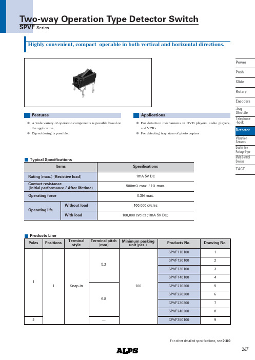
267Power Push SlideRotary Encoders Jog Shuttle Telephone -hook Detector Vibration Sensors Dual-in-line Package TypeMulti ControlDevicesTACTHighly convenient, compact operable in both vertical and horizontal directions.ApplicationsA wide variety of operation components is possible based on the application.Dip soldering is possible.FeaturesFor detection mechanisms in DVD players, audio players,and VCRsFor detecting tray sizes of photo copiersOperating life1mA 5V DC0.3N max.500m max. / 1 max.100,000 cyclesRating max. Resistive load ItemsSpecificationsContact resistanceInitial performance / After lifetime Operating force100,000 cycles 1mA 5V DCWithout loadWith loadTypical SpecificationsProducts LinePoles115.26.82Positions12345678Drawing No.Products No.Terminal pitchmm100Minimum packingunit pcs.Snap-inTerminal styleSPVF110100SPVF120100SPVF130100SPVF140100SPVF210200SPVF220200SPVF230200SPVF2402009SPVF350100For other detailed specifications, see P.300Two-way Operation Type Detector SwitchSPVF Series268Power Push Slide Rotary Encoders Jog Shuttle Telephone -hook DetectorVibration Sensors Dual-in-line Package Type Multi Control Devices TACTON starting positionTotal travel position4.52.84-14.76.36.85910.71.15.2ø15.81.23.5 5.44-1.14-1ø155ON starting positionTotal travel position4.52.84-14.75.756.2910.71.15.2 ø15.81.23.5 5.44-1.14-1ø151235.44-1.14-1ø1545.44-1.14-1ø15510.71.16.8ø17.41.23.562.84-16.27.88.359ON starting positionTotal travel position74-1.14-1ø15Unit : mmDimensionsStyleNo.PC board mounting hole dimensionsTwo-way Operation Type Detector Switch SPVF Series5.25.8ON starting positionTotal travel position 4.513.62.84-115.2595.72.61.710.71.1ø11.23.5ON starting positionTotal travel position4.52.84-17.89.9510.7597.214.710.71.1ø11.23.55.25.8269Power Push Slide RotaryEncoders Jog Shuttle Telephone -hookDetectorVibration Sensors Dual-in-line Package TypeMulti Control Devices TACTUnit : mmDimensionsStyleNo.PC board mounting hole dimensions610.71.16.8ø17.41.23.562.84-16.27.257.759ON starting positionTotal travel position74-1.14-1ø157810.71.16.8ø17.41.23.5615.12.84-116.7595.72.61.7Total travel position ON starting position4-1.154-17ø14-1.154-17ø110.71.16.8ø17.41.23.562.84-19.311.4512.25914.77.2Total travel positionON starting position95-ø16.8510.7583421Terminal No.1234123Terminal No.123Circuit DiagramTwo-way Operation Type Detector Switch SPVF Series9.95Total travel positionON starting position3.251.15.32.72.958.3842-ø111.48.683-152-15.57.4199.50.7300Power Push Slide Rotary Encoders Jog Shuttle Telephone -hook Detector Vibration Sensors Dual-in-line Package Type Multi Control Devices TACTSeriesItemsOperating temperature rangeRating max. Resistive loadElectrical performanceMechanical performance DurabilityEnvironmental performanceInitial contact resistance Insulation resistance Voltage proof Robustness ofterminal Robustness ofactuator SolderabilityOperating life without loadOperating life with loadColdDry heat Damp heatResistancetosolderingheatManual solderingDip soldering Reflow solderingVibration Products SpecificationsSPPB0.1A 30VDC 0.1A 30V DC50,000cycles 2 max.50,000cycles 2 max.SPVE SPPW8 10 to 60 0.1A 30VDC 0.1A 12VDC 1 max.1 max.500m max.3N for 1 min.3Nfor 1 min.10N10N20 2 for 96h25 2 for 96h20 2for 96h100,000cycles 2 max.0.1A 30V DC 100,000cycles 2 max. 0.1A 12V DC 50,000cycles 1 max.2 max.SPVM 1mA 5V DC 1N for 1 min.5N50,000cycles 5 max.1mA 5V DC 50,000cycles 5 max.260 5 ,5 1s255 5 ,5 1s350 10 , 3s 10 350 5 , 3s max.100M min.100V DC 100V AC for 1 min.0.5N for 1 min.5N230 5 , 3 0.5s85 2 for 96h40 2 , 90 to 95%RH for 96h50,000cycles 1 max.Please see P.300350 5 , 3s max.300 5 , 5s max.10 to 55 to 10Hz/min., the amplitude is 1.5mm for all the frequencies,in the 3 direction of X, Y and Z for 2 hours respectively500m max.SPVF 3N for 30 s 3N for 1 min.1N10N5N 40 2 for 96h100,000cycles 1 max.1mA 5V DC 100,000cycles 1 max.260 5 ,5 1s260 5 ,5 1s300 10 , 3s 10 SSCT SSCU 0.1A 12V DC 20m max.70m max.100M min.250V DC 250V AC for 1 min.20 2 for 96h10,000cycles 40m max.10,000 cycles 100m max. 0.1A 12V DC 10,000cycles 60m max. 0.1A 12V DC 10,000cycles 150m max.350 10 ,3s100.5N for 1 min.5NSPVP1mA 5V DC 5 max.100M min.100V DC 100V AC for 1 min.50,000cycles 10 max.1mA 5V DC 50,000cycles10 max.350 5 , 3s max.Please see P.302Detector Switches。
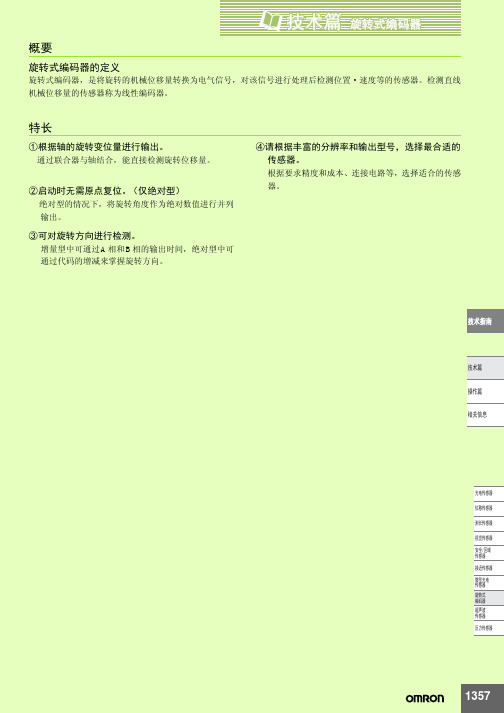
OMRON编码器说明书
᪡㆛
Ⳍֵ݇ᙃ
串行传送
对应同时输出多位数据的通常并联传送,可采用由一个 传送线进行系列化输出数据的形式,目的是节省连线, 在接受信号侧则变换成并联信号后使用。
⬉ܝӴᛳ఼
ԡ鼠Ӵᛳ఼
⌟䭓Ӵᛳ఼
㾚㾝Ӵᛳ఼ ᅝܼऎඳ Ӵᛳ఼ 䖥Ӵᛳ఼ ᖂൟ⬉ܝ Ӵᛳ఼ ᮟ䕀ᓣ 㓪ⷕ఼ 䍙ໄ⊶ Ӵᛳ఼ य़Ӵᛳ఼
1 增量式或绝对式
考虑到容许的成本,电源接通时的原点可否恢复、控 制速度、耐干扰性等,选择合适的类型。
2 分解率精度的选择
在考虑组装机械装置的要求精度和机械的成本的基础 上,选择最适合的产品。一般选择机械综合精度的1/2 ~1/4精度的分辨率。
3 外形尺寸
选定时还要考虑安装空间与选定轴的形态 (中空轴、 杆轴类)。
18位置,则代码的范围为从14位置到49位置。从49 ᡔᴃᣛफ
位置切换到14位置时,只改变1位,可见保持了格雷
码的性质。通过将该代码转换至14位置,就能转换
至从0位置开始的代码,然后进行使用。
(4) BCD代码
ᡔᴃ㆛
二进10进制代码 (Binary Coded Decimal Code)。
是分别用2进符号表示10进制各位的代码。
Ӵᛳ఼ 䖥Ӵᛳ఼
ᖂൟ⬉ܝ Ӵᛳ఼ ᮟ䕀ᓣ 㓪ⷕ఼ 䍙ໄ⊶ Ӵᛳ఼
य़Ӵᛳ఼
项目
特长
构造
输出波形
·本 型 号 能 根 据 轴 的 旋 转 位 移 量,
输出脉冲列。
其方式是通过其他计数器,计算输
ফܗܝӊ AⳌ⣁㓱 BⳌ⣁㓱
出脉冲数,通过计数检测旋转量。
·希望知道某输入轴位置的旋转量, 先按基准位置,使计数位的计数 值复位,然后再用计数器把由该 䕈 位置发出的脉冲数累加起来。
KOYO 旋转光电编码器说明书

KOYO旋转编码器一览表(下表列出各系列的基本型,其它规格机种在各章节中详述)类型增量型系列名 TRD-S系列 TRD-SH系列 TRD-N系列外观(基本型)Φ38×30mm轴径:Φ6mmΦ38×30mm轴径:Φ8mmΦ50×35mm轴径:Φ8mm 特点外径Φ38mm/长度30mm分解能最高2500P/R体积小、价格低高速应答(200kHz)分辩率范围宽中空型可直接与传动轴连接外径Φ38mm/厚度30mm分解能最高2500P/R体积小、价格低高速应答(200kHz)分辩率范围宽厚度为35mm的薄形设计。
适合各种环境的保护构造。
分辨范围宽。
坚固的Φ8mm主轴。
5~30V宽电压范围推拉输出易于延长电缆分辩率 10~2500(脉冲/转) 10~2500(脉冲/转)1~2500(脉冲/转)输出信号形式A·B二相+Z相A·B二相+Z相A·B二相+Z相最高响应频率 200kHz 200kHz 100kHz允许最高转速 6000rpm 6000rpm 5000rpm电源电压 TRD-S□A:5~12VDC±10%TRD-S□B:12~24VDC±10%TRD-S□V:5VDC±5%TRD-SH□A:5~12VDC±10%TRD-SH□B:12~24VDC±10%TRD-SH□V:5VDC±5%4.75~30VDC输出形式 NPN开路集电极输出线驱动输出NPN开路集电极输出线驱动输出推拉输出带部分负载短路保护回路径向 20N 20N 50N荷重轴向 10N 10N 30N起动转矩 0.001N·m以下 0.001N·m以下防尘型:0.003 N·m以下防尘防滴型:0.002 N·m以下保护构造 IP40:仅防尘型 IP40:仅防尘型 IP50:防尘型IP65:防尘防滴型使用环境温度 -10~+70℃ -10~+70℃ -10~+70℃类型增量型系列名 TRD-NH系列 TRD-J系列 TRD-GK系列外观(基本型)Φ50×35mm轴径:Φ8mmΦ50×50mm轴径:Φ8mmΦ78×60mm轴径:Φ10mm 特点中空型可直接与传动轴连接厚度35mm薄形设计提供防油型,适用于较差的环境中分辩率范围宽轴径8mm坚固耐用5~30V宽电压范围推拉输出易于延长电缆外径Φ50mm小体积轴径Φ8mm。
KOYO 旋转光电编码器说明书

100N 50N 0.1N·m 以下
IP65:防尘防滴型 -10~+70℃
类型 系列名 外观(基本 型)
TRD-NA 系列
绝对值型 TRD-K 系列
TRD-KL 系列
特点
分辩率
输出信号 形式 最高响应 频率 允许最高 转速 电源电压 输出形式 荷 径向 重 轴向 起动转矩 保护构造 使用环境 温度
环境条件 使用环境温度 保存温度 使用环境湿度 耐电压 绝缘阻抗 耐振动 耐冲击 保护构造
-10~+70℃ -25~+85℃ 35~85%RH(无凝露) 500VAC(50HZ/60HZ)1 分钟 50MΩ以上 变位振幅 0.75mm,10~50HZ,3 轴方向各 1 小时 490m/s2 11ms 3 轴方向各 3 回 仅防尘型:IP40
径向 荷重
轴向 起动转矩
保护构造 使用环境温度
Φ50×35mm 轴径:Φ8mm
中空型可直接与传动轴连 接 厚度 35mm 薄形设计 提供防油型,适用于较差
的环境中 分辩率范围宽 轴径 8mm 坚固耐用 5~30V 宽电压范围 推拉输出易于延长电缆 1~2500(脉冲/转)
A·B 二相+Z 相
100kHz
型号一览 种类 主轴
外观
中空轴
型号构成
型号 TRD-S□A TRD-S□B TRD-S□V
TRD-SH□A TRD-SH□B TRD-SH□V
电源电压 4.5~13.2VDC 10.8~26.4VDC 4.75~5.25VDC
4.5~13.2VDC 10.8~26.4VDC 4.75~5.25VDC
Φ50×50mm 轴径:Φ8mm
外径Φ50mm 小体积轴径 Φ8mm。 耐冲击振动的金属光栅。 5~30V 宽电压范围 推拉输出易于延长电缆
OMRON编码器说明书

启动转矩
旋转式编码器的轴旋转启动时必须的旋转力矩。通常旋 转时,一般取比本值低的值。轴为防水用密封设计时, 启动转矩的值较高。
1360
ᡔᴃ㆛ᮟ䕀ᓣ㓪ⷕ఼
惯性力矩
表示旋转式编码器的旋转启动、停止时的惯性力的大 小。
轴容许力
是加在轴上的负载负重的容许量。径向以直角方向对轴 增加负重,而轴向以轴方向增加负重。 两者都为轴旋转时容许负重,该负重的大小对轴承的寿 命产生影响。
00 0 0 1 0 1
6
0 0 1 1 0 00 0 1 0 1
00 0 0 1 1 0
7
0 0 1 1 1 00 0 1 0 0
00 0 0 1 1 1
8
0 1 0 0 0 00 1 1 0 0
00 0 1 0 0 0
9
0 1 0 0 1 00 1 1 0 1
00 0 1 0 0 1
10
0 1 0 1 0 00 1 1 1 1
1361
ᡔᴃ㆛ᮟ䕀ᓣ㓪ⷕ఼
中空轴型 (空心轴型)
旋转轴为中空轴形状,通过将驱动侧的轴直接与中空孔 连接,可节省轴方向的空间。 以板簧为缓冲,吸收驱动轴的振动等
金属盘
编码器的旋转板 (盘)是用金属制成的,与玻璃旋转板 (盘)相比,更强化了耐冲击性。但受到狭缝加工的制 约,不能应用于高分辨率。
伺服装置
③可对旋转方向进行检测。
增量型中可通过 A 相和 B 相的输出时间,绝对型中可 通过代码的增减来掌握旋转方向。
④请根据丰富的分辨率和输出型号,选择最合适的 传感器。
根据要求精度和成本、连接电路等,选择适合的传感 器。
ᡔᴃᣛफ
ᡔᴃ㆛ ᪡㆛ Ⳍֵ݇ᙃ
⬉ܝӴᛳ఼ ԡ鼠Ӵᛳ఼ ⌟䭓Ӵᛳ఼ 㾚㾝Ӵᛳ఼ ᅝܼऎඳ Ӵᛳ఼ 䖥Ӵᛳ఼ ᖂൟ⬉ܝ Ӵᛳ఼ ᮟ䕀ᓣ 㓪ⷕ఼ 䍙ໄ⊶ Ӵᛳ఼ य़Ӵᛳ఼
编码器使用说明书

1,优点:体积适中,直接测量直线位移,绝对数字编码,理论量程没有限制;无接触无磨损,抗恶劣环境,可水下1000米使用;接口形式丰富,量测方式多样;价格尚能接受。
2,缺点:分辨度1mn不高;测量直线和角度要使用不同品种;不适于在精小处实施位移检测(大于260毫米)。
19.※我是个新手,想请问,一个圆盘,分50个点,要实现定位控制,转速很慢,是要用到绝对型编码器吗?怎么找原点呢?50个位置定位是360度均匀等分吗?绝对编码器的编码都是2的幕次方,没有360度均匀50 等分的,要近似,看精度要求有多高,选多高线数的编码器,如果精度要求不是太高的话,用8位256线的就可以了。
编码器的每个位置都有唯一编码,编码为零的就可以作为零点,也可以任意位置定义为零,其他位置与其比较计算。
如果可以用参考点的话,也可以用增量式的,因速度慢,应该选3000线或以上的,每圈一个零位。
20.※请简单介绍:RS-232、RS-422与RS-485标准及应用?RS-232、RS-422与RS-485都是串行数据接口标准,最初都是由电子工业协会(EIA)制订并发布的。
目前RS-232是PC机与通信工业中应用最广泛的一种串行接口。
RS-232被定义为一种在低速率串行通讯中增加通讯距离的单端标准。
RS-232采取不平衡传输方式,即所谓单端通讯。
RS-422、RS-485与RS-232不一样,数据信号采用差分传输方式,也称作平衡传输,它使用一对双绞线,将其中一线定义为A,另一线定义为B。
通常情况下,发送驱动器A、B之间的正电平在+2〜+6V,是一个逻辑状态,负电平在-2〜6V,是另一个逻辑状态。
另有一个信号地C,在RS-485中还有一“使能”端,而在RS-422 中这是可用可不用的。
“使能”端是用于控制发送驱动器与传输线的切断与连接。
当“使能”端起作用时,发送驱动器处于高阻状态,称作“第三态”,即它是有别于逻辑“1”与“ 0”的第三态。
ENI-1024 增量磁旋转编码器 KIT 用户手册和安装指南说明书

ENI-1024Incremental magnetic rotary encoder KITUser’s Manual and Installation GuideContents1. Safety, policy and warranty.1.1. Safety notes.1.2. Policy.1.3. Warranty.2. Electric specifications.2.1. Operation ranges.2.2. Incremental channels signals.2.3. Differential outputs.2.4. LED indicator.3. Installation guide.3.1 . Description of working.3.2 . Pinout of the connector.3.3 . Installation of the device.1. Safety, policy and warranty.1.1. Safety NotesThe device should not be used where it can cause personal injury, death or high financial loss.1.2. PolicyCNCdrive cannot take responsibility for any personal injury and/or financial loss caused by their devices failure or caused by following an error in this documentation.1.3. WarrantyWe give 12 months of standard warranty period with our ENI-1024 KIT encoders. Customers may send back the device within 15 days from reception date if they are not satisfied with the performance.Using the devices outside of the specified electrical ranges may cause permanent damage to the device and voids warranty.ESD notice: Use ESD protection gloves when installing the device.ESD damage caused by human body discharge to the device excludes from warranty.2. Electric specifications.2.1.Operation ranges.Property Min Typ Max Unit NotesSupply voltage4.5 55.5 VDCSupply current 38 mA Outputs not connectedHigh level output current-20 mALow level output current20 mAEncoder resolution - 1024 - Counts perrevolution In 4X decoding mode. Counting A and B channels’ both the rising and the falling edges.Maximum countfrequency512 kHzHysteresis 2 Counts Hysteresis introduced to avoid flickering of the encoder outputsDifferential non-linearity +-0.176 degreesIntegral non-linearity +-1.4 degrees With magnet displacementof 0.485mm out of thecenter of the sensor. Maximum alloweddisplacement of magnet from center of the sensor. 0.485 mmMeasured on the radiusfrom center of the sensorIC.Ambient temperaturerange-55 +85 °C2.2. Incremental channel signals.The device outputs 90°shifted incremental A and B channel signals. The signal A leads signal B in one rotational direction and signal B leads A in the opposite rotational direction of the magnet. In addition an index signal output is provided which signal is produced on the zero mechanical position, one LSB pulse width and one pulse per full revolution duration.The following figure shows the encoder signals:To avoid the flickering of the encoder signals a 2 counts (LSB) length of hysteresis is introduced.The following figure shows the 2 counts hysteresis:2.3. Differential outputs.All output signals A and B and Index are output as differential signals. This means that each signal has it's negated output too. The differential signals can be transferred in twisted wire pairs to long distance. The differential outputs are produced with the onboard 26LS31 differential line driver chip.The following figure shows the A and _A channel signals in normal operation (when counting) and also in an external short circuit of the wires. The figure is similar for B to _B and for Index to _Index channels:2.3. LED indicator.The device has one LED on the top (connector) side of the panel. The LED indicates if the magnet used for the position sensing is in the correct range for the device to read the mechanical position. If the magnet is in the correct range (1-2mm distance from the surface of the sensor IC) then the LED lights. If the magnet is out of the good range (too close or too far) then the LED light goes off. The sign of the LED makes the correct alignment of the magnet easy to check.3. Installation guide.3.1. Description of working.The device is a rotary encoder module for position sensing in rotary motion. The aluminium hub which includes a magnet at it's end can be attached to a motor shaft. To make the device working place the printed circuit board of the module above the magnet keeping 1-2mm distance with the magnet centered to the center mark on the PCB. The device producing differential incremental A and B channel signals, 1024 edges per full revolution of the magnet. In addition there is an index and _Index output with one counts output per every full rotation. The output signals can be used to measure the relative position of the rotation.The following picture shows the bottom of the printed circuit board with the sensor IC located in the center of the PCB:3.2. Pinout of the connector.The device has a 10 pin IDC crimpable connector. This connector is used to connect the5Volts to power the device and to route out the incremental output signals.The connector is crimpable to a 10 pin ribbon cable or for example to wires of a CAT5/6 patch cable.The following picture and diagram shows the pinout of the connector:Pin number Description1 Ground power input2 +5Volts power input3 Index signal output4 _Index signal output5 A signal output6 _A signal output7 B signal output8 _B signal output9 NC. No internal connection10 NC. No internal connection3.3. Installation of the device.To following steps should done to install the device:a.) Make 2pcs of tapped M3 drills around the motor backshaft (or to the shaft of the installation). The tapped drills should be made on a 25.4 (1 Inch) circle around the midpoint of the shaft on a line alignment (180°) to eachother.b.) Place the magnet holder hub to the motor's backshaft. The hub is pre-drilled with 3mm diameter and should be drilled up if nessessary. Drilling it up can be made on a drillpress with a standard HSS drilling tool. Take care to not drill into the magnet located at the other end of the hub.c.) bolt in the hexagonal spacers to the tapped holes done in point a.d.) crimp your cable to the connector on the encoder PCB.e.) Place the encoder PCB to the top of the hexagonal spacers with the ICs facing down and the connector and LED facing upward. Bolt the PCB to the top of the hexagonal spacers with the supplied M3 screws through the 3mm drills on the PCB.f.) Adjust the hub on the shaft with keeping a 1-2mm distance of the magnet on the hub end to the IC surface on the PCB. Lock the hub to the shaft with bolting the screw located in the side of the hub.g.) Power up the device with providing 5Volts Voltage to it's power pins and check the LED on the top of the PCB. The LED continious on state means a correct alignment of the magnet. If the LED is off after powered means the magnet is out of the correct range and needs to be aligned.For more information visit:e-mail: info@cncdrivePlease consider the enviroment before printing this document.。
TT电子EN11系列旋转编码器说明书

Issue E 11/2023 Page 2
Rotary Encoder Model EN11 Series
Q Type
Shaft Types
H = 5mm L 15 20 25 30 P 7 7 11 14 T 6 6 10 12 M 2 224
H = 7mm L 15 20 25 30 P 7 7 11 14 T 6 6 10 12 M 1 124
10mA/5Vdc 10mA
300Vac/1mA, 1 minute 100M ohms at 250Vdc/ 1 mA
2.0ms max. 5.0ms max. 100 RPM max. 10mA/5Vdc 100 miliohms Continuous
General Note TT Electronics reserves the right to make changes in product specification without notice or liability. All information is subject to TT Electronics’ own data and is considered accurate at time of going to print.
Model Styles Available
Top adjust, with switch, threaded bushing Top adjust, without switch, threaded bushing Top adjust, with switch, plain bushing Top adjust, without switch, plain bushing Side adjust, with switch, threaded bushing Side adjust, without switch, threaded bushing Side adjust, with switch, plain bushing Side adjust, without switch, plain bushing
布瑞特单圈绝对值旋转编码器 RS485 用户手册说明书

布瑞特单圈绝对值旋转编码器RS485产品说明书深圳布瑞特科技有限公司ShenZhen Briter Technology Co.Ltd产品优势特性●RS485数字通讯信号输出,数字输出信号既有多圈值、单圈绝对值;●采用标准的ModBus-RTU通讯规约,支持组态王、Intouch、FIX、synall 等流行软件,能与AB、西门子、施耐德、GE等国际著名品牌的设备及系统之间实现数据通信;●单圈编码器在不掉电情况下可作电子多圈编码器使用(此功能非断电记忆),最高可达百万圈;增加返回速度功能,便于使用者计算;●单圈量程范围内任何位置都是唯一的,即使有干扰或断电运动,都不会丢失位置信息;●单圈分辨率有1024(10bit)、4096(12bit)、16384(14bit)、32768(15 bit),量程范围内最高可实现0.01度的分辨率;●所有参数均可通过电脑的RS485通讯进行设定,可在任意位置设定零点,因此安装编码器时可将设备停留任意位置,无需考虑本编码器的旋转位置、即可固定好连接轴,通电后只要在外部引线处或通过RS485通讯进行一次置零操作即可自动修正;●特别适用于塔式起重机、矿山起重机、施工升降机、机床、3D打印机、自动化流水线、工业机器人、印刷机械、包装机械、物流机械、移动广告屏幕滑轨等设备的高度、行程、角度及速度的可靠/精确测量。
产品型号说明型号:RS485接口--3D 模型以及相关资料请到布瑞特科技官网下载。
尺寸型号图1:输出6mm IP54尺寸型号图2:输出轴8mm IP54机械尺寸线出口方向与3个M3安装孔的角度关系是随机的D 字型轴尺寸比例5:1螺纹孔深6mm尺寸型号图3:盲孔8mm IP54尺寸型号图4:输出6mm IP67尺寸型号图5:输出8mm IP67注意事项●编码器属于精密仪器,请轻拿轻放、小心使用,尤其对编码器轴请勿敲、撞击及硬拽等。
●编码器与机械连接应选用柔性连接器或弹性支架,应避免刚性联接不同心造成的硬性损坏。
光洋TRD-J曾量旋转编码器中文说明书
二相带原点输出型 TRD-J□-RZ□
二相带原点输出型 TRD-J□-RZV□
输出基准 TTL5V
10TTL
10TTL
―
负载电源电压
≤DC30V
≤DC30V
―
*26LS31 或相当品
(输出信号与 TTL 一致)
RZ
机械规格
环境条件
起动转矩 轴惯性力矩 轴容许荷重 容许最高转速*1 轴承寿命
≤0.003N·m(+20℃) 防尘·防滴型: ≤0.02N·m
防尘型:IEC 规格 IP50
防尘·防滴型:IEC 规格 IP65
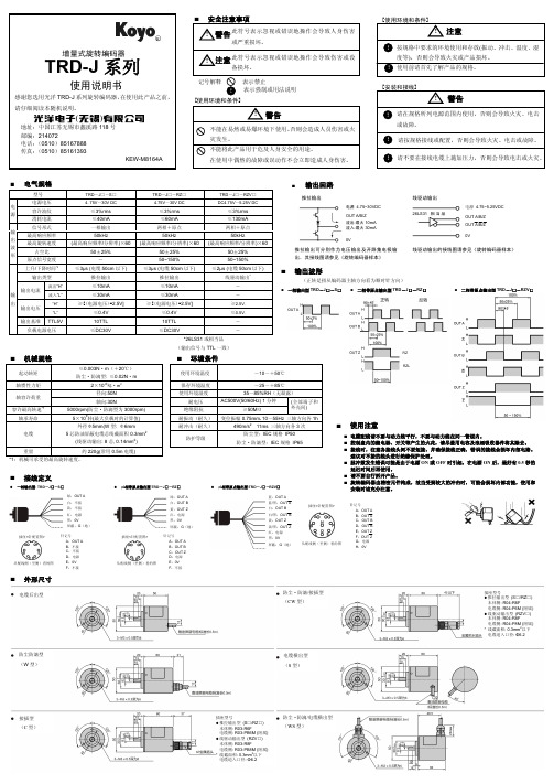
接线定义
一相输出型: TRD-J□-S□
二相带原点输出型:TRD-J□-RZ□
二相带原点输出型:TRD-J□-RZV□
RZL
使用注意
电缆配线请不要与动力线平行,不要与动力线在同一管道内。 控制盘内的继电器、开关等产生的火花,请尽量用电容及浪涌吸收器件将其除去。 接线时,注意各接线头间不要短接,并确保接线正确,错误的接线会损坏内部电路。 建议对不接的线头进行绝缘保护处理。 脉冲数发生错误可能是由于电源 ON 或 OFF 时引起,在电源 ON 后,最好有 0.5 秒的 延迟时间后再使用。 请不要自行拆开产品。 旋转编码器由精密元件构成,故当受到较大的冲击时,可能会损坏内部功能,使用和 安装时请充分注意。
电气规格
输出回路
型号
电源电压 电
容许波纹 源
消耗电流
信号形式
输 最高响应频率
出
最高旋转速度 波
形
占空比
原点信号宽度
TRD―J□―S□ 4. 75V~30V DC
≤3%rms ≤40mA 一相输出
50kHz (最高响应频率/分辨率)×60
微型旋转编码器QY1503-CDZ SDI5E用户手册说明书
微型旋转编码器QY1503-CDZ/SDI5ERev.2.2QY1503-CDZ/SDI5E 是一款非接触式磁增量位置编码器,可用于精确测量单圈360 º内的任意角度。
可输出正交脉冲信号或者步方向信号作为增量式编码器使用。
内置芯片由非接触式磁绝对位置编码器由磁电阻(MR)/霍尔角度传感器和数字处理芯片集成而成。
芯片配合磁铁实现360°角度测量和转速测量。
产品说明一、工作原理编码器采用的是磁电技术。
由两个MR/霍尔电桥构成。
当磁场旋转电桥输出四组正弦波信号组合成A、B、C、D,每个正弦波相差90度相位差(相对于一个周波为360度),将C、D信号反向,叠加在A、B两相上,可增强稳定信号;另每转输出一个Z相脉冲以代表零位参考位。
由于A、B两相相差90度,可通过比较A相在前还是B相在前,以判别编码器的正转与反转,通过Z(零位)脉冲,可获得编码器的零位参考位。
信号经过芯片处理后,输出标准的ENC(ABZ/SDI)信号。
二、产品特点磁电编码器具有结构简单、体积小、寿命长、安装方便、功耗小、频率高、耐振动、不怕灰尘、油污及盐雾等的污染或腐蚀等特点。
另外,还具有无触点、输出波形清晰、无抖动、位置重复精度高等优点。
※电压推挽输出※ 3.3V / 5 V 电源※低功耗※高精度,低角度误差※360度非接触※ABZ/SDI三相输出※体积小,重量轻三、应用领域旋转编码器是测量旋转运动、角速度的传感器,也可与机械测量设备一起使用,例如丝杠,测量直线运动。
※智能车※机床※电机※工业机器人※运送设备※测量,测试和检验设备技术规格电气规格最大额定参数•电压:-0.3 - 6V•ESD:+/- 4kV工作参数•工作电压*:3.3/5V•电流消耗:最大8 mA•输出:CMOS输出驱动能力4mA•响应频率:1MHz•线数*:64/ 256 /512/1024 / 4096机械规格材料•外壳:铝合金•轴:不锈钢•排线*:15 cm电缆,带或不带连接器力学参数•转子转动惯量:0.5·10–7 kgm2•启动扭矩::0.001 Nm(25 °C时)•轴最大负荷:径向1N,轴向0.5N•轴向窜动:±0.05 mm•工作寿命:MTBF > 50000 h•重量:≈11 克•机械允许转速:10000 rpm环境规格环境温度•最高工作温度:80 °C•最低工作温度:-40 °C防护等级•EN 60 529 IP64注意: 1. 请不要超出额定范围使用。
欧姆龙E6C3-C系列增量式旋转编码器说明书
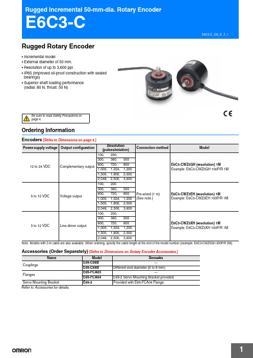
Rugged Rotary Encoder•Incremental model•External diameter of 50 mm.•Resolution of up to 3,600 ppr.•IP65 (improved oil-proof construction with sealed bearings)•Superior shaft loading performance (radial: 80 N, thrust: 50 N)Be sure to readSafety Precautionsonpage 4.Ordering InformationEncoders [Refer to Dimensions on page 4.]Note:Models with 2-m cable are also available. When ordering, specify the cable length at the end of the model number (example: E6C3-CWZ5GH 300P/R 2M).Accessories (Order Separately) [Refer to Dimensions on Rotary Encoder Accessories .]Refer to Accessories for details.Power supply voltage Output configurationResolution (pulses/rotation)Connection methodModel12 to 24 VDC Complementary output100, 200,Pre-wired (1 m)(See note.)E6C3-CWZ5GH (resolution) 1MExample: E6C3-CWZ5GH 100P/R 1M300,360,500600,720,8001,000,1,024,1,2001,500,1,800,2,0002,048,2,500,3,6005 to 12 VDC Voltage output100,200E6C3-CWZ3EH (resolution) 1MExample: E6C3-CWZ3EH 100P/R 1M300,360,500600,720,8001,000,1,024,1,2001,500,1,800,2,0002,048,2,500,3,6005 to 12 VDC Line-driver output100,200,E6C3-CWZ3XH (resolution) 1MExample: E6C3-CWZ3XH 100P/R 1M300,360,500600,720,8001,000,1,024,1,2001,500,1,800,2,0002,048,2,500,3,600NameModel RemarksCouplings E69-C08B ---E69-C68B Different end diameter (6 to 8 mm)FlangesE69-FCA03---E69-FCA04E69-2 Servo Mounting Bracket provided. Servo Mounting Bracket E69-2Provided with E69-FCA04 Flange.E6C3-CRatings and Specifications*1.An inrush current of approximately 9 A will flow for approximately 0.1 ms when the power is turned ON.*plementary Output The complementary output has two outputtransistors (NPN and PNP) as shown below. Thesetwo output transistors alternately turn ON and OFFdepending on the high or low output signal. When using them, pull up to the positive power supplyvoltage level or pull down to 0 V. The complementary output allows flow-in or flow-out of the output current and thus the rising and falling speeds of signals are fast. This allows a long cable distance. They can be connected to open-collector input devices (NPN, PNP).*3.The line driver output is a data transmission circuit compatible with RS-422A and long-distance transmission is possible with a twisted-pair cable. (AM26LS31equivalent)*4.The maximum electrical response speed is determined by the resolution and maximum response frequency as follows:Maximum electrical response speed (rpm) = × 60This means that the Rotary Encoder will not operate electrically if its speed exceeds the maximum electrical response speed.*5.The phase Z signal is output when cut face D on the shaft and the cable connection direction are as shown in the following diagram (output position range: ±15°).ItemModelE6C3-CWZ5GHE6C3-CWZ3EHE6C3-CWZ3XHPower supply voltage 12 VDC −10% to 24 VDC +15%,ripple (p-p): 5% max. 5 VDC −5% to 12 VDC +10%,ripple (p-p): 5% max.Current consumption *1100 mA max.Resolution (pulses/rotation)100, 200, 300, 360, 500, 600, 720, 800, 1,000, 1,024, 1,200, 1,500, 1,800, 2,000, 2,048, 2,500, 3,600Output phases Phases A, B, and Z *5Phases A, A, B, B, Z, and Z Output configuration Complementary outputs *2Voltage output (NPN output)Line driver output *3Output capacity Output voltage: VH = Vcc -3 V min.(IO = 30 mA)VL = 2 V max.(IO = −30 mA)Output current: ±30 mAOutput resistance: 2 k ΩOutput current: 35 mA max.Residual voltage: 0.7 V max.AM26LS31 equivalentOutput current: High level: IO = −10mALow level: IS = 10 mAOutput voltage:VO = 2.5 V min.VS = 0.5 V max.Maximum response frequency *4125 kHz (65 kHz when using phase Z reset) Phase difference between outputs90°±45° between A and B (1/4 T ± 1/8 T)Rise and fall times of output 1 μs max.(Cable length: 2 m, Output current: 30 mA) 1 μs max.(Cable length: 2 m, Output current: 35mA) 1 μs max.(Cable length: 2 m, IO: −10 mA, IS: 10mA)Starting torque 10 mN·m max. at room temperature, 30 mN·m max. at low temperature Moment of inertia 2.0 × 10⁻⁶ kg·m 2 max.; 1.9 × 10⁻⁶ kg·m 2 max. at 500 P/R max. Shaft loadingRadial 80 N Thrust50 NMaximum permissible speed 5,000 r/min Protection circuitsPower supply reverse polarity protection, Output load short-circuit protection ---Ambient temperature range Operating: −10 to 70°C (with no icing), Storage: −25 to 85°C (with no icing)Ambient humidity range Operating/Storage: 35% to 85% (with no condensation)Insulation resistance 20 M Ω min. (at 500 VDC) between current-carrying parts and case Dielectric strength 500 VAC, 50/60 Hz for 1 min between current-carrying parts and caseVibration resistance Destruction: 10 to 500 Hz, 150 m/s 2 or 2-mm double amplitude for 11 min 3 times each in X, Y, and Z directions Shock resistance Destruction: 1,000 m/s 2 3 times each in X, Y, and Z directions Degree of protection IEC 60529 IP65, in-house standards: oilproof Connection method Pre-wired Models (Standard cable length: 1 m)MaterialCase: Aluminum, Main unit: Aluminum, Shaft: SUS303Weight (packed state)Approx. 300 gAccessoriesInstruction manual Note: Coupling, mounting bracket and hex-head spanner are sold separately.Maximum response frequencyResolutionE6C3-C I/O Circuit DiagramsNote:1.The shielded cable outer core (shield) is not connected to the inner area or to the case.2.The phase A, phase B, and phase Z circuits are all identical.3.Normally, connect GND to 0 V or to an external ground.E6C3-CSafety PrecautionsRefer to Warranty and Limitations of Liability .This product is not designed or rated for ensuring safety of persons either directly or indirectly.Do not use it for such purposes.Do not use the Encoder under ambient conditions that exceed the ratings.● Wiring ConnectionsCable Extension Characteristics•When the cable length is extended, the output waveform startup time is lengthened and it affects the phase difference characteristics of phases A and B. Conditions will changeaccording to frequency, noise, and other factors. As a guideline, use a cable length of 10 m * or less. If the cable must be more than 10 m, use a Model with a Line-driver Output or Complementary Output.(max. length for line-driver output: 100 m,max. length for complementary output: 30 m)*Recommended CableConductor cross section: 0.2 mm 2Spiral shieldConductor resistance: 92 Ω/km max. (20°C)Insulation resistance: 5 Ω/km min. (20°C)•The output waveform startup time changes not only according to the length of the cable, but also according to the load resistance and the cable type.•Extending the cable length not only changes the startup time, but also increases the output residual voltage.● ConnectionSpurious pulses may be generated when power is turned ON and OFF. Wait at least 0.1 s after turning ON the power to the Encoder before using the connected device, and stop using the connected device at least 0.1 s before turning OFF the power to the Encoder. Also, turn ON the power to the load only after turning ON the power to the Encoder.(Unit: mm)DimensionsTolerance class IT16 applies to dimensions in this datasheet unless otherwise specified.EncoderAccessories (Order Separately)Servo Mounting Bracket E69-2Refer to Accessories for details.WARNINGPrecautions for Correct UseE6C3-CWZ @@H40±0.2 mm 2, Insulator diameter: 1.1 mm), Standard length: 1 mThe E69-C08B Coupling is sold separately.Couplings E69-C08B E69-C68BFlanges E69-FCA03E69-FCA04Terms and Conditions of SaleCertain Precautions on Specifications and UseOMRON CANADA, INC. • HEAD OFFICEToronto, ON, Canada • 416.286.6465 • 866.986.6766 • OMRON ELECTRONICS DE MEXICO • HEAD OFFICEMéxico DF • 52.55.59.01.43.00 •01-800-226-6766•**************OMRON ELECTRONICS DE MEXICO • SALES OFFICEApodaca,N.L.•52.81.11.56.99.20•01-800-226-6766•**************OMRON ELETRÔNICA DO BRASIL LTDA • HEAD OFFICE São Paulo, SP , Brasil • 55.11.2101.6300 • .brOMRON ARGENTINA • SALES OFFICE Cono Sur • 54.11.4783.5300OMRON CHILE • SALES OFFICE Santiago • 56.9.9917.3920OTHER OMRON LATIN AMERICA SALES 54.11.4783.5300Authorized Distributor:E6C3-C_DS_E_7_1 01/14 Note: Specifications are subject to change.© 2015 Omron Electronics LLC Printed in U.S.A.Automation Control Systems• Machine Automation Controllers (MAC) • Programmable Controllers (PLC) • Operator interfaces (HMI) • Distributed I/O • Software Drives & Motion Controls• Servo & AC Drives • Motion Controllers & Encoders Temperature & Process Controllers • Single and Multi-loop ControllersSensors & Vision• Proximity Sensors • Photoelectric Sensors • Fiber-Optic Sensors • Amplified Photomicrosensors • Measurement Sensors • Ultrasonic Sensors • Vision SensorsIndustrial Components• RFID/Code Readers • Relays • Pushbuttons & Indicators• Limit and Basic Switches • Timers • Counters • Metering Devices • Power SuppliesSafety• Laser Scanners • Safety Mats • Edges and Bumpers • Programmable Safety Controllers • Light Curtains • Safety Relays • Safety Interlock SwitchesOMRON AUTOMATION AND SAFETY • THE AMERICAS HEADQUARTERS • Chicago, IL USA • 847.843.7900 • 800.556.6766 • OMRON EUROPE B.V. • Wegalaan 67-69, NL-2132 JD, Hoofddorp, The Netherlands. • +31 (0) 23 568 13 00 • www.industrial.omron.eu。
电梯伺服驱动控制的旋转编码器说明书

July 2017Product InformationECN 1313ECN 1325ERN 1387Rotary Encoders withPlane-Surface Coupling for Elevator Servo Drive ControlཷProduct Information ECN 1313/ECN 1325/ERN 1387 7/2017 2ECN/ERN 1300 seriesRotary encoders with integral bearings for elevator technology• Simple installation• Rigid shaft coupling• Plane-surface coupling for large mounting tolerances• Uniform dimensions for various electrical interfaces= Bearing of mating shaft= Bearing of encoder= Required mating dimensions= Measuring point for operating temperature1 = Screw plug, width A/F 3 and 4. Tightening torque: 5+0.5 Nm2 = PCB connector3 = Self-tightening screw M5 x 50 DIN 6912 width A/F 4, tightening torque 5+0.5 Nm4 = M10 back-off thread5 = M6 back-off thread6 = Max. permissible tolerance during motor shaft rotation ±1.5 mm7 = Max. permissible static radial offset of motor shaft in indicated direction ±0.13 mm8 = Direction of shaft rotation for output signals as per the interface descriptionProduct Information ECN 1313/ECN 1325/ERN 1387 7/20173See Interfaces of HEIDENHAIN Encoders brochure2)Velocity-dependent deviations between the absolute value and incremental signals 3)One sine and one cosine signal per revolution 4)Evaluation optimized for KTY 84-1305)Compensation of mounting tolerances and thermal expansion, not dynamic motion 6)As per standard for room temperature; for operating temperature U p to +100 °C: 300 m/s 2Up to +115 °C or +120 °C: 150 m/s 2Product Information ECN 1313/ECN 1325/ERN 1387 7/20174Cable shield connected to housing U P = Power supply; T = T emperatureSensor: The sensor line is connected in the encoder with the corresponding power line.Vacant pins or wires must not be used.Electrical connection Pin layoutsU P = Power supply; T = T emperatureSensor:The sensor line is connected internally with the corresponding power line.Vacant pins or wires must not be used.1)Only for cables inside the motor housingProduct Information ECN 1313/ECN 1325/ERN 1387 7/20175Product Information ECN 1313/ECN 1325/ERN 1387 7/20176HEIDENHAIN measuring equipmentPWM 20T ogether with the ATS adjusting andtesting software, the PWM 20 phase angle measuring unit serves for diagnosis andadjustment of HEIDENHAIN encoders.DRIVE-CLiQ is a registered trademark of SIEMENS AG.For more information, see the PWM 20/ATS Software Product Information document .DR. JOHANNES HEIDENHAIN GmbH Dr.-Johannes-Heidenhain-Straße 583301 Traunreut, Germany {+49 8669 31-0|+49 8669 32-5061E-mail:******************www.heidenhain.de1085677 · 03 · A · 02 · 7/2017 · PDFT est cable for connection to PWM 20/PWT 100This Product Information supersedes all previous editions, which thereby become invalid. The basis for ordering from HEIDENHAIN is always the Product Information documentedition valid when the order is made.PWT 100The PWT 100 is a testing device for checking the function and adjustment of incremental and absolute HEIDENHAIN encoders. Thanks to its compact dimensions and robust design, the PWT 100 is ideal for mobile use.Y ou can fi nd more information in the Product Information PWT 100.PWT 100Encoder inputOnly for HEIDENHAIN encoders• EnDat• Fanuc Serial Interface• Mitsubishi High Speed Interface • Panasonic Serial Interface • Y askawa Serial Interface • 1 V PP • 11 µA PP • TTLDisplay 4.3” color fl at-panel display (touch screen)Voltage supply DC 24 VPower consumption: max. 15 W Operating temperature 0 °C to 40 °C Protection EN 60 529IP20Dimensions145 mm x 85 mm x 35 mm。
DELTA ROE台达旋转式编码器 说明书

台達旋轉式編碼器使用說明 台达旋转式编码器使用说明DELTA ROTARY OPTICAL ENCODER INSTRUCTION SHEET(繁體版)輸出訊號之電路將編碼器連接至接收端前,請先根據下表確認輸出訊號種類。
1. 線路連接表ES/EH/ET 系列 將屏蔽線(裸線)連接到應用設備之接地端,以使其有更高品質的輸出訊號。
AS/AH 系列 (AXX-XXCXXXXX,AXX-XXVXXXXX) 線材顏色 功能 線材顏色功能 紅 Vcc 藍24黑 0V 紫 25 棕 20 灰 26 橘 21 白 27 黃 22 粉紅 28 綠23淡藍29MH4/MT4 系列CS7 系列2. 輸出型式 ES/EH/ET 系列Vcc0VoutputVcc0V0VVccoutput電壓輸出開集極差動推挽AS/AH 系列 (AXX-XXCXXXXX,AXX-XXVXXXXX)Vcc0Voutput電壓輸出開集極MH4/MT4/CS7系列Vcc0V差動(简体版)输出信号之电路将编码器连接至接收端前,请先根据下表确认输出信号种类。
1. 线路连接表ES/EH/ET 系列将屏蔽线(裸线)连接到应用设备之接地端,以使其有更高品质的输出信号。
AS/AH 系列 (AXX-XXCXXXXX,AXX-XXVXXXXX) 线材颜色 功能 线材颜色 功能红 Vcc 蓝 24 黑 0V 紫25 棕 20灰 26 橘 21白 27 黄 22粉红 28 绿 23淡蓝 29MH4/MT4 系列CS7 系列2. 输出形式 ES/EH/ET 系列Vcc0VoutputVcc0V0VVccoutput電壓輸出開集極差動推挽AS/AH 系列 (AXX-XXCXXXXX,AXX-XXVXXXXX)Vcc0Voutput電壓輸出開集極MH4/MT4/CS7系列Vcc0V差動(English Version)CIRCUIT OF OUTPUT SIGNALSBefore connecting the encoder wirings to the receiver, please identify the type of the output signal with the specification. 1. Connection Table ES/EH/ET SeriesConnect the shield wire (bare wire) with the grounding end of equipment for better performance.AS/AH Series (AXX-XXCXXXXX,AXX-XXVXXXXX) Wire ColorFunctionWire ColorFunction Red Vcc Blue 24Black 0V Purple 25 Brown 20Gray 26 Orange 21 White 27 Yellow 22 Pink28Green 23Light Blue29MH4/MT4 SeriesCS7 Series2. Output Circuit ES/EH/ET SeriesVcc0V outputVcc0V 0VVccoutputVoltage OutputOpen-Collector Line Driver Push-PullAS/AH Series (AXX-XXCXXXXX,AXX-XXVXXXXX)Vcc0VoutputVoltage OutputOpen-CollectorMH4/MT4/CS7SeriesVcc0VLine Driver。
- 1、下载文档前请自行甄别文档内容的完整性,平台不提供额外的编辑、内容补充、找答案等附加服务。
- 2、"仅部分预览"的文档,不可在线预览部分如存在完整性等问题,可反馈申请退款(可完整预览的文档不适用该条件!)。
- 3、如文档侵犯您的权益,请联系客服反馈,我们会尽快为您处理(人工客服工作时间:9:00-18:30)。
提示在使用建筑升降机操作控制系统之前,请您仔细阅读本说明,以确保正确使用。
不正确的使用可能会造成控制系统工作不正常、发生故障或损坏、乃至发生人身伤害事故。
因此使用前应认真阅读本说明书,严格按照使用说明使用。
电气规格供电电源输入电压:AC220V 最大电流:0.5A输出通道外接电压:AC380V 最大电流:2A输入通道输入电压:DC12V 最大电流:20mA数码显示及功能键1开机自检,声音提示,手动找到最低点后窗口显示01。
2输入想要到达的楼层后,按“上升”或“下降”键,系统会启动吊笼(轿厢)的运行,运行到输入目标后,系统自动切断驱动电机电源使吊笼(轿厢)停止在所输入楼层。
3在任何时候按“停止”键都会使驱动电机停止运转。
4在吊笼停止时,按“调上”或“调下”键,会使吊笼(轿厢)向上或向下点动运行。
5按下“最高”键,显示闪烁,输入系统运行最高楼层后,再按下“最高”键,系统则记忆最高楼层数据,以后输入超过最高楼层的运行目标时,系统会提示输入错误,起到软最高限位的作用。
6按下“最低”键,显示闪烁,输入系统运行最低楼层后,再按下“最低”键,系统则记忆最低楼层数据,以后输入超过最低楼层的运行目标时,系统会提示输入错误,起到软最低限位的作用。
最低楼层只能选择“-4”、“-3”、“-2”、“-1”和“01”层,如输入其它数字,系统记忆为默认的“01”层。
注:主机引出的的两根细导线为电源开关引线,短接为供电状态,电压为直流12V,最大电流500mA,可接空气开关或其它小型、微型开关。
输出通道的接线输出通道端子是与配电箱进行接线,调整三相电源的相序,使按下配电箱“上升”、“下降”和“停止”按钮时,吊笼能够正确的运行和停止。
按照系统接线图将输出接线端子用导线连接到配电箱相应位置。
变频器变速的接线输出通道还提供的一组常开/常闭继电器作为变频时变频起始点开始的接口,供变频调速时本系统输入电压为AC220V ,切勿接错。
如误接其它等级电压会对本系统造成毁灭性损害!本系统控制电压等级为AC380V选择使用。
变频调速的起始点在系统中已经设置好,起始时间在系统初始化时低度运行距离中设置即可,不用变频时,将此端口闲置。
此功能只提供调速的起始点,频率的调节时间和调节范围请参照变频调速器说明书设定。
旋转编码器的安装将旋转编码器按照下图安装。
因旋转编码器属于精密光电器件,使用中要尽量避免剧烈震动,并加装防护罩。
将旋转编码器的正极接12V端子、负极接12G端子,两根信号输入线分别接编码端子。
互换旋转编码器AB相的信号接线,让吊笼上升时上升指示灯同时点亮,让吊笼下降时只有一个下降指示灯点亮。
见下面方向指示图旋转编码器和双向霍尔开关只选择一个即可,根据施工升降机的具体情况进行选择。
旋转编码器选型:NPN输出,DC12V,AB相输出,100线双向霍尔开关选型:NPN输出,DC12V,双向霍尔开关的安装1、先将霍尔开关的正极接12V端子、负极接12G端子,两根信号输入线分别接编码端子。
将检测磁铁吸附安装在低速旋转主轴上(或高速主轴、或卷筒外缘),注意磁铁极性(正确为:霍尔开关接近时,指示灯亮)正确,否则霍尔开关不能检测。
如果安装多个磁铁,要将磁铁均匀分布,且每个都能被检测到。
吊笼运行单位高度,检测到的磁铁数量越多,平层越准确。
2、将霍尔开关预安装到固定支架上,调整霍尔开关与磁铁的距离为0.7cm。
位置甲位置乙位置丙3、旋转霍尔开关,缓慢旋转电机主轴,使位置甲状态时指示灯A或B点亮,使位置乙状态时指示灯A与B都点亮,使位置丙状态时B或A点亮。
即由位置甲-乙-丙变化时,霍尔指示灯的点亮顺序为A-AB-B或B-AB-A,反转时指示灯灭的顺序正好相反。
固定好霍尔开关。
方向指示4、互换霍尔传感器A、B信号线的接线,让吊笼上升时两个上升指示灯同时闪烁,让吊笼下降时只有一个下降指示灯闪烁。
基准开关的安装将基准开关安装在吊笼最低起始上升点位置处(不一定是下限位开关处),让吊笼内平面与进料平面等高时,基准开关刚好输出信号动作为准。
可以选用行程开关或红外反射开关作为基准开关(自行购买)。
行程开关的接线:用导线将行程开关的常开点的一端与12V端子连接,常开点另一端与基准端子连接。
红外反射开关的接线:用导线将红外开关的正极与12V端子连接,负极与12G端子连接,输出端与基准端子连接。
辅助基准开关的安装(齿条驱动时可以不使用)推荐使用红外反射开关作为辅助基准开关。
将辅助基准开关的正极与12V端子连接,负极与12G端子连接,输出端与辅助端子连接。
作为平层准确的最终检测,辅助基准开关起着非常重要的作用,在吊笼到达辅助开关的楼层时,准确平层检测信息会传递到主机,这样,所有的累计误差都被清零,从而达到任意楼层都能精准停靠的目的。
辅助基准开关不必每层都安装,推荐每隔4层安装一个。
辅助基准开关的调整在系统初始化之后进行,由于使用设备的不同,安装方法稍有不同。
1、钢丝绳卷扬机:将辅助开关安装在提升机架体上,让吊笼运行到分别需要停靠的不同楼层位置时能够刚好动作。
需要安装多个辅助基准开关时,将输出信号并联。
2、齿轮齿条升降机:将辅助开关安装在吊笼上,让吊笼运行到分别需要停靠的不同楼层位置时,安装专用反射板,使辅助开关刚好动作。
为了让平层准确,将反射板用不透光物体遮挡一部分,只留下1.5―2.0倍红外反射开关的直径的缝隙,让反射开关能够准确检测即可。
方式1 方式2 方式3方式1的红外反射开关选用PNP常开型,方式2和方式3的红外反射开关选用PNP常闭型。
本说明全部按照方式2作为蓝本来介绍的,如选用其他方式,根据此图更改即可。
笼门检测开关的安装系统预留了笼门检测的功能,用来防止在吊笼未关闭时电梯运行。
出厂前已经设置成笼门检测无效的状态,调试完毕后,打开继电器模块外壳,找到电路板左侧标有“MEN”字样的跳线,剪断后,笼门检测即更改为有效状态。
系统初始化1、楼层定位:将功能端子和12V端子用导线短接。
将吊笼升到需要停靠的位置,输入相应的楼层号(最低层为1层),按下“最高”键,主机记忆相应的楼层位置。
重复操作,定位其它楼层。
2、低速运行距离:将功能端子和12V端子用导线短接。
将吊笼停在中间楼层位置,按下“最低”键,显示闪烁,闪烁完毕后,手动操作吊笼上升一段距离,且必须是上升一段距离,再次按下“最低”键。
(注:如不用变频调速,也必须设置此项,且低速运行距离必须大于下降刹车时吊笼下滑距离,推荐低速运行距离为3米)3、上升提前停止:将功能端子和12V端子用导线短接。
将吊笼停在中间楼层位置,按下“调上”键,显示闪烁,闪烁完毕后,再按下“调上”键,吊笼上升一段距离自动停止。
4、下降提前停止:将功能端子和12V端子用导线短接。
将吊笼停在中间楼层位置,按下“调下”键,显示闪烁,闪烁完毕后,再按下“调下”键,吊笼下降一段距离自动停止。
5、楼层显示下调距离:将功能端子和12V端子用导线短接。
将吊笼停在中间楼层位置,按下“上升”键,显示闪烁,闪烁完毕后,手动操作吊笼上升一段距离,且必须是上升一段距离,再次按下“上升”键。
(推荐楼层显示下调距离为1米)6、设定最高楼层:将短接导线去掉,按下“最高”键,显示闪烁,闪烁完毕后,输入最高楼层数,再按下“最高”键。
7、设定最低楼层:将短接导线去掉,按下“最低”键,显示闪烁,闪烁完毕后,输入最低楼层数,再按下“最低”键。
最低楼层只能输入“-4”、“-3”、“-2”、“-1”和“01”层,如输入其它数字,系统记忆为默认的“01”层。
本系统只有进行初始化设置后才能正常工作。
本系统只有在接线正确的情况下才能进行初始化设置。
系统初始化后必须将功能端子和12V端子短接导线去掉。
安装调试注意事项1、变压器接线:变压器输入端接入电压为交流220V,错误接入380V会烧毁变压器。
2、平层控制器电源接线:平层控制器接入电压为直流12V和直流5V,引线标记分别为:黄12V 绿12G 红5W 黑5G ,接线错误会导致控制器内部的烧毁,首先只接好直流电源引线,通电正常后再连接其他引线。
3、系统初始化:系统初始化7个步骤的顺序可以打乱;初始化过程中会出现显示不正确现象;初始化步骤2(低速运行距离)数据不正确时会出现吊笼停止位置错误的现象;步骤5(楼层显示下调距离)数据不正确时会出现显示错误现象,需要重新设置。
影响平层精度的因素1、刹车的滑行距离:无论电磁抱闸或者液压抱闸还有锥式电机都不能保证刹车时没有滑行距离,滑行距离的长短与吊笼的载重量、刹车片的间隙都有很大的关系,为了获得很好的平层精度,要及时调整刹车器件的间隙,及时检查刹车片的磨损,让其工作在最佳状态。
2、刹车前的初始速度:初始速度的高低,会直接影响刹车的滑行距离,有条件的用户会使用变频调速等方式来降低刹车前的初始速度,不但会提高平层的精度,还会减少机械冲击增大机械设备使用寿命。
3、吊笼的载重:载重量同样是决定刹车需要克服的惯性量大小的主要因素。
4、提前停车距离的测量:提前停车就是减去刹车滑行距离提前给电动机断电,从而提高平层精度的手段,提前停止的测量就有时候会显得很重要。
工地工况的复杂,可能需要每隔一段时间就要对平层停靠点、提前停止的距离进行一次设置。
为了让平层更加准确,在提前停车距离的测量时需要充分考虑吊笼的工况,在吊笼上升时大部分是重载;下降时大部分是轻载或空载。
这就需要设定上升提前停止的时候需要让吊笼重载,在设定下降提前停止时需要让吊笼空载或轻载。
5、数字编码的密度:为了达到控制设备运行、停止的目的,必须对吊笼运行高度进行编码,无论是哪种的编码方式,对主机来说都是一个101010……的数字信号,那么这个“1”与下一个“1”之间的对应着一定的吊笼运行距离,这个对应的距离就是编码密度,距离越小编码密度就越大。
编码的密度越大,与实际的误差就越小,平层精度就越高,所以吊笼运行单位高度,检测到的“1”的数量越多,平层越准确,如果条件允许,建议将检测磁铁安装在电机的高速主轴上或者使用编码密度更高的光电旋转编码器。
6、辅助基准开关的位置:对于钢丝绳驱动的升降机来说,加装辅助基准开关的目的是消除钢丝绳打滑、伸长所带来的累计误差,从而让平层精度更高。
但是为了降低设备成本,本着最小投入,最大满足使用要求的原则,并没有每一个停靠楼层都加装,并且没有将上升辅助基准与下降辅助基准分开设置,所以有时候辅助基准开关反而会加大平层误差,背离了初衷,这就需要辅助基准的安装同样要最大的满足使用要求。
本着最小投入,最大满足使用要求的原则,安装基准开关和辅助基准开关时,需要有一定的技巧:在辅助基准开关的安装时都按照上升时停靠准确来确定安装位置,在基准开关的安装时按照下降时准确停靠来确定安装位置,尽量减小基准开关与最近的辅助基准开关的距离。
