电磁刹车DWS40使用说明书..
Handy 40cm 2200W 电动链锯 WEECS40 使用说明书

WARNINGDANGER WARNING CAUTIONWARNINGDo not connect either core to the earth pinCLASS IIKNOW YOUR MACHINEWARNINGDo not connect the chainsaw to the mains before it is assembled completely. Always use gloves when handling the chain. 1. Rear Handle 2. Throttle Trigger 3.Lock Button 4. Oil Cap 5.Front Handle 6.Chain Brake 7. Guide Bar 8. Chain 9. Spike10. Blade Guard 11. Locking Knob & Chain Tensioner12. Side Cover 13. Drive Sprocket 14. Guide 15. Cutting Direction Symbol16. Oil Lever Gauge13 14 1516WARNINGEnsure the chain tensioning catch on the guide bar is facing outwards.Fit the chain onto the drive sprocket and guide bar, so the fastening bolt and two guide fins fit into the keyway of the guide bar.Press the cover plate firmly onto the machine and screw on the cover plate, with the locking knob.CHAIN DIRECTION CHAIN TENSIONING CATCHWARNINGbar. This should be done, by using one hand to raise the chain against the weight of the machine.3-6mmIf the chain loses tension, unscrew the locking knob/chain tensioning knob completely. Then screw on theCAUTIONThe Chainsaw IS NOT supplied filled with chain oil. It is essential to fill the oil canister with chain oil beforeThe safety button (3) can now be released.chain bar) comes into contact with a log or wood, or when the chain becomes jammed.Use the chainsaw only with secure footing.The chain must be running at full speed before it makes contact with the wood.Sawing is optimized when the chain speed remains steady during cutting. Beware when reaching the end ofguide bar when the second notch is being made.Make the felling back cut (Y) at least 50 mm higher than the horizontal notching cut. Keep the the bottom up to avoid binding the chainsaw.BUCKING A LOG(underbuck). Then make the finished cut by over bucking to meet the first cut.make the finished cut by under bucking the lower 2/3 to meet the first cut.When bucking on a slope always stand on the uphill side of the log, as illustrated. When “cutting through”, to protrudes (a) must be fitted into the bar hole.CAUTIONCAUTIONClean the tool after each use. Failure to carry out proper cleaning can result in damage to the appliance orcause it to malfunction.WARNINGWaste electrical products should not be disposed of with household waste. Please recycle where facilities exist. Check with your Local Authority or retailer for recycling advice.PARTS DIAGRAM - WEECS40 1938261001REPLACEMENT PARTSPlease find on the following pages, parts lists and drawings for your machine. Should you require a replacement part, please call our Spares Team on 01793 333212, option 1 for assistance.Webb recommends the use of Handy Parts oils, fuel additives, nylon lines pre-packed parts for all our machines.EC DECLARATION OF CONFORMITYWe Handy Distribution Ltd - SN3 5HY (Importer) declare that the product:Designation: 40cm Electric 2200w ChainsawModel(s): WEECS40Product No.: 1938261001Type/Serial No. As per rating label on machineMotor Wattage: 2200 WattsWorking Width: 406mm/ 16inComplies with the following directives:Machinery Directive 2006/42/ECThe conformity assessment procedure followed was in accordance with:EN60745-2-13:2009+A1:10, EN60745-1:2009+A11:2010,Noise Directive 2000/14/ECSound Power Level L WA: 108 dB(A) - uncertainty: 3.0 dB(A) According to 2000/14/ECVibration a hv: 4.5 m/s2 - uncertainty K: 1.5 m/s2Electro Magnetic Directive 2004/108/ECThe conformity assessment procedure followed was in accordance with:EN 55014-1:2006/+A1:2009/+A2:2001, EN 55014-2:2015, EN 61000-3-2:2014, EN 61000-3-3:2013,EN 61000-3-11:2000RoHS Directive 2011/65/EUNotified Bodies:Intertek Testing Services Shanghai, Building No.86, 1198 Qinzhou Road (North), Shanghai 200233, P.R China Authorised signatory and technical file holderDate: 14/05/2020Signature:Name: Mr Simon BelcherPosition: ChairmanCompany: Handy Distribution LtdAddress: Murdock Rd, Swindon, Wiltshire, SN3 5HY.1. Model Number2. Serial & Product NumberWebb Lawnmowers Murdock RoadDorcanSwindonWiltshireSN3 5HY。
电磁刹车培训ppt
刹车两侧各有一个1½ "溢流管, 此管不允许堵塞,以防止内腔水位上升致
使轴承锈蚀。应当指出,电磁涡流刹车的
冷却水必须在溢流管有一定的水流出时为 适宜, 从而保证冷却水在涡流刹车内有一 定的水位高度。否则会造成涡流刹车过热,
甚至烧坏线圈,导致涡流刹车损坏而无法 正常工件。
2)、风冷涡流刹车
采用了风源为离心式通风机
从刹车排出的冷却水经过一个漏斗返回 水箱,漏斗与排水接头稍离一段距离以保证 排水流畅。当无回水泵时,水箱安装的位置 应与涡流刹车内的冷却水有足够的水位差, 使冷却水能自流返回。
水质要求含有较低的矿物质(PH值不超 过7~7.5),与内燃机水套内的水质要求相 近,如果水质不合要求,则需进行化学处理, 当刹车用于海洋时,也可以装置专门的海水 冷却器。
体
图
6.上呼吸器
7.下呼吸器
1. 端盖 两侧端盖
安装
2. 转子
刹车的转子通 过齿式离合器与绞车 滚筒轴相联,由绞车 滚筒驱动,与滚筒同 速旋转。转子既是磁 路的一部分,又是电 路的一部分,采用电 工钢制成。它和定子 磁极、工作气隙构成 刹车的完整磁路。
3. 机座
4. 定子
刹车的定子由磁极 和激磁线圈构成。50、 70型成对使用,磁极是 磁路的一部分,采用电 工钢成,,这种材料的 导磁系数高,矫顽力小, 以满足下钻时制动扭矩 大,而起空吊卡时无用 制动扭矩小的要求。
2.滚筒无级调速,下钻速度任意控制。下钻时,司钻 通过操作司钻开关可平滑地调节激磁电流,就可改变制动扭 矩,无级地调节滚筒转速。
3.由于下钻时几乎有效地减小主刹车的刹车力矩,因 而主刹车负担大大减轻,刹带片与刹车毂的磨损与消耗大幅 度减少,寿命成倍增长,钻井成本下降,经济效益十分显著。
Danfoss 40 系列汽车潜行系统控制单元部件手册说明书

DanfossFebruary2023 Power Steering40SeriesSteeringControlUnits001002 AX442774853332en-0001011Piece Seal ActualDisplacementcm3/r[in3/r]1230[75] 1555[95] 1965[120] 2460[150] 3030[185]21519-00521519-00621519-00721519-00821519-00957,7[2.27]72,9[2.87]91,9[3.62]115,1[4.53]142,0[5.59]16148-83616148-84416148-85216148-86116148-871Part No.Width mm[in.]Part No.Ref.No.4GerotorRef.No.1Socket Head Cap Screw95,2[3.75]114,3[4.50]133,3[5.25]155,4[6.12]180,8[7.12]Length mm[in.]Ref.No.Part Number DescriptionQty.Per Unit 17250001-136Seal,O-ring,50,5mm [1.99in.]ID 1149233-001Seal,25,4mm [1.00in.]ID1128329-000Race,Bearing 2115544-000Bearing,Needle Thrust11814296-000Ring,Retaining119844-000Seal,Dust,31,7mm [1.25in.]OD 17NSS Housing18NSS Sleeve,Control 1NSS Spool,Control 1**10NSS Spring,Centering 6/814451-000Pin,Centering 13250001-048Seal,O-ring,120,4mm [4.74in.]ID 3521847-000Plate,Wear 1621514-000Drive 14*Gerotor 11*Screw,Cap 7Seal Kit —Contains Parts Indicated by X.X X XX*—See Chart on Page 2for Information on Specific Models9221509-000Cap,End11321513-000Retainer,Front164468-000**—Ref.10Sold only in Kit form,Spring Kit No.64428-001Includes 8Springs,Use 6springs on 40Series Closed center and Load Sensing Steering Control Units (8Springs are required on 35Series and 40Series Open Center Steering Control Units).NSS —Not Sold Separately1230[75]1555[95]1965[120]2460[150]3030[185]281-1001281-1002281-1003281-1004283-1001283-1002283-1003283-1004283-100540Series SCUClosed Center **Closed Center Units with Neutral Bleed 2,3l/min [.6GPM]at 172bar [2500PSI]System Load Circuit Rated Flow l/min [GPM]Non Load Reaction Open Center Non Load ReactionLoad SensingNon Load Reaction 1–5/16-12O-ring Port Size 1–5/16-121–5/16-12151[40]Actual Displacement cm 3/r [in 3/r]—Product Number SignalN/AN/ADynamic281-1005151[40]151[40]282-1001**282-1002**282-1003**282-1004**282-1005**282-1010282-1011282-1012282-1013282-10141–5/16-12EachOrderMustIncludetheFollowing:HowtoOrderReplacementParts 1.Product Number 2.Date Code3.Part Name4.Part Number5.Quantity of PartsFor More Detailed Information Contact your Danfoss representative.Specifications and performance data,Catalog No.11-872When servicing SteeringControl Unit refer toRepair Information No.7-308.Thisrepair manualliststools required,step by step disassembly and reassembly procedures.Danfoss Power Solutions is a global manufacturer and supplier of high-quality hydraulic and electric components. We specialize in providing state-of-the-art technology and solutions that excel in the harsh operating conditions of the mobile off-highway market as well as the marine sector. Building on our extensive applications expertise, we work closely with you to ensure exceptional performance for a broad range of applications. We help you and other customers around the world speed up system development, reduce costs and bring vehicles and vessels to market faster.Danfoss Power Solutions – your strongest partner in mobile hydraulics and mobile electrification.Go to for further product information.We offer you expert worldwide support for ensuring the best possible solutions foroutstanding performance. And with an extensive network of Global Service Partners, we also provide you with comprehensive global service for all of our components.Local address:DanfossPower Solutions GmbH & Co. OHG Krokamp 35D-24539 Neumünster, Germany Phone: +49 4321 871 0DanfossPower Solutions ApS Nordborgvej 81DK-6430 Nordborg, Denmark Phone: +45 7488 2222DanfossPower Solutions (US) Company 2800 East 13th Street Ames, IA 50010, USA Phone: +1 515 239 6000DanfossPower Solutions Trading (Shanghai) Co., Ltd.Building #22, No. 1000 Jin Hai Rd Jin Qiao, Pudong New District Shanghai, China 201206Phone: +86 21 2080 6201Danfoss can accept no responsibility for possible errors in catalogues, brochures and other printed material. Danfoss reserves the right to alter its products without notice. This also applies to products already on order provided that such alterations can be made without subsequent changes being necessary in specifications already agreed.All trademarks in this material are property of the respective companies. Danfoss and the Danfoss logotype are trademarks of Danfoss A/S. All rights reserved.Products we offer:•Cartridge valves •DCV directional control valves•Electric converters •Electric machines •Electric motors •Gear motors •Gear pumps •Hydraulic integrated circuits (HICs)•Hydrostatic motors •Hydrostatic pumps •Orbital motors •PLUS+1® controllers •PLUS+1® displays •PLUS+1® joysticks and pedals•PLUS+1® operator interfaces•PLUS+1® sensors •PLUS+1® software •PLUS+1® software services,support and training •Position controls and sensors•PVG proportional valves •Steering components and systems •TelematicsHydro-GearDaikin-Sauer-Danfoss。
电磁刹车操作及维护保养规程
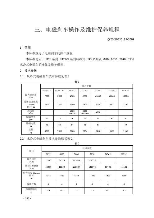
三、电磁刹车操作及维护保养规程Q/SH10250185-20041 范围本标准规定了电磁刹车的操作规程本标准适应于SDF系列、FDWS系列风冷式,DS系列及5030、6032、7040、7838水冷式电磁车的操作及维护保养。
2 技术参数2.1 风冷式电磁刹车技术参数见表12.2 水冷式电磁刹车技术参数购买表23.1 首次使用前应做绝缘测量,绝缘电阻应大于1MΩ。
3.2 检查盘车,刹车转子应转动灵活。
3.3 在刹车两侧轴承腔内注入锂基脂。
3.4 在牙嵌或齿式离合器的滑动与转动部分注入适量润滑脂。
3.5 呼吸孔畅通无油污。
3.6 油冷式控制柜内油质良好,油面距离上端盖20mm左右,保证内部电器元件浸入冷却油内。
3.7 控制箱各电器元件安装牢固。
3.8 司钻控制箱手柄牢固、灵活无卡滞。
3.9 保证控制箱与刹车主体接线正确牢固。
3.10 风冷式电磁刹车进排风门畅通无阻;风机转动灵活,报警装置完好。
3.11 水冷式电磁刹车准备充足的刹车冷却软化水,水压开关及报警装置完好。
4 启动4.1 闭合电源开头。
4.2 检查控制柜内指标灯状态及仪表参数,确认指标正确。
4.3 风冷式启动风机,水冷式启动水泵。
5 操作与运行5,1 在下钻过程中,用电磁刹车手柄控制下放速度。
5.2 运行中冷水温度与流量应符合要求,轴承升温不大于70℃,轴承处无冷却水渗出;刹车坚固件无松动;冷却风机运转正常,变压器及油冷式控制柜温度正常。
5.3 每次下钻前检查维护轴承、牙嵌、离合器、拨叉。
检查控制柜仪表,指标灯指标正常。
5.4 及时清除进排风口杂物。
5.5 下钻完毕后,风冷刹车应继续通风,刹车冷却后再关闭风机。
5.6 停机时关闭电源开关。
6 维护保养6.1 月检查维护6.1.1 检查连接电缆有无损伤、无老化现象,绝缘良好。
6,1,2 清除控制柜积尘,检查控制器触点。
6.1.3 测量变压器、控制柜、操作手柄的输入、输出电压、电流并做好记录。
6.1.4 清洗呼吸器。
FDWS型风冷式电磁涡流刹车说明书
FDWS型风冷式电磁涡流刹车使用说明书上海申通石油机械厂一、概述风冷式电磁涡流刹车是在吸取国外水冷式电磁涡流刹车先进技术基础上结合我国油田特点和需要研制的石油钻机绞车的一种新颖辅助刹车。
保证在钻井进程中进行下钻作业时对下放钻具产生靠得住又可调的非摩擦式的强有力制动,使钻具平稳地座落在转盘或卡瓦上,在几乎不利用主刹车(刹把)的情形下完成下钻作业。
它将水冷式涡流刹车优良的性能与高效有效的通风冷却系统融为一体,扬长避短,既综合了水冷式涡流刹车的优势,又克服了水冷式涡流刹车由于采纳水冷却而造成的缺点。
采纳强迫通风冷却,实现了钻机绞车和辅助刹车在冷却方式上的创新与冲破。
具有制动扭矩大,制动特性好;流筒无级调速,任意操纵钻具下放速度,实现下钻时的加速、等速和减速进程;工作靠得住,寿命长,保护简单;主刹车刹带片和刹车轮网的磨损大幅度减少,主刹车寿命延长,钻井维修工作量减小,钻井本钱下降,经济效益十分可观;工人劳动强度减轻,环境和空气污染取得操纵,社会效益显著;采取强迫通风冷却,取代了水冷,幸免了国内外水冷式涡流刹车和传统水刹车在利用中由于水源、水质及低温而造成的水垢、堵塞、冻裂、结构复杂等诸多不利和不良后果等特点,最大限度地知足了钻井工艺的需要,适应在我国任何地域,任何油田,尤其在严寒地域油田利用,深受钻井工人欢迎。
二、用途风冷式电磁涡流刹车是一种无摩擦刹车,没有任何磨损件。
在高速和低速时都具有很高的制动扭矩,不像水刹车那样在低速时扭矩几乎为0,而且制动扭矩的调剂又十分方便,司钻只要操作司钻开关即可调剂自如,劳动强度减轻,要取消制动,只要将司钻开关关闭即可。
在一样情形下,只要操作司钻开关而没必要利用刹把(主刹车)就能够靠得住地操纵钻具下放速度。
将钻具平稳地座落在转盘或卡瓦上。
由于是风冷,再也不发生像水冷不时而发生的设备冻裂冻坏、结垢、堵塞,刹车轮网表面裂纹等现象,能有效地减轻主刹车负担,延长主刹车寿命。
另外,利用这种刹车,也不需要单向聚散器,因此是目前石油钻机最为理想的一种辅助刹车。
电磁刹车DWS40使用说明书
DWS40电磁涡流刹车使用说明书上海申通石油机械厂有限公司一、性能及说明DWS40型涡流刹车用作钻深为4000米的海洋或陆地钻机的辅助刹车,既可绞车成套供应,也可为矿场已经使用的钻机配套作为单独部件供应。
1、技术规范最大扭矩 60000N.m钻井深度 4000m作用原理感应涡流制动线圈个数 4每个线圈额定电阻(20°C时) 5.39Ω线圈绝缘等级H级励磁功率 12KW励磁电流(两串两并时)40A需用冷却水量285L/min最大出水温度(当进水温度42°C时) 72°C重量 6500kg二、结构电磁涡流刹车由刹车主体、可控硅整流装置及司钻开关等三部分组成。
1、刹车主体它由两个基本部分组成,如图一所示。
其一为静止部分,称为定子;其二为转动部分,称为转子。
在定子与转子之间有一定的气隙,称为工作气隙,电磁涡流刹车的刹车主体采用外电枢结构的型式,也就是说,其转子在定子外面旋转。
刹车的定子由磁极和激磁线圈构成。
磁极是磁路的一部分,采用电工钢制成,这种材料的导磁系数高,矫顽力小,以满足下钻时有用制动扭矩大,而起空吊卡时无用制动扭矩小的要求。
激磁线圈是刹车的电路部分,工作时通以直流电流,它固定于磁极上,与磁极组成一个整体成为定子。
刹车在运行时要产生大量的热量,因此激磁线圈采用了耐高温的电磁线与相应的绝缘材料,以保证线圈在高温下仍具有良好的绝缘性能。
图一电磁涡流刹车结构示意图1. 端盖2. 转子3. 机座4. 定子5. 激磁线圈6.上呼吸器7.下呼吸器刹车的转子通过齿式离合器与绞车滚筒轴相联,由绞车滚筒驱动,与滚筒同速旋转。
转子既是磁路的一部分,又是电路的一部分,采用电工钢制成。
它和定子磁极、工作气隙构成刹车的完整磁路。
2.可控硅整流装置:它由整流变压器和可控硅半控桥式整流电路组成。
用以将钻机交流发电机或交流电网供给的交流电压变成可调直流电压,给激磁线圈通以可调直流电流。
考虑到使用电磁涡流刹车进行下钻作业时,其下钻速度的调整精度、调节系统的稳定性以及过渡过程动态品质方面的指标都要求不高,因此采用比较简单的闭环调节系统即可满足钻井工艺的要求。
电磁缝隙制动器实验指南说明书
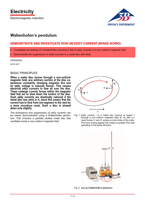
ElectricityElectromagnetic induction1 / 2Waltenhofen’s pendulumDEMONSTRATE AND INVESTIGATE HOW AN EDDY-CURRENT BRAKE WORKSUE304040004/16 ALFBASIC PRINCIPLESWhen a metal disc moves through a non-uniform magnetic field, any arbitrary section of the disc ex-periences constantly changing magnetic flux and an eddy voltage is induced therein. This causes electrical eddy currents to flow all over the disc. These undergo Lorentz forces within the magnetic field that act to slow down the motion of the disc. Such eddy currents are drastically reduced if the metal disc has slots in it, since this means that the current has to flow from one segment to the next by a more circuitous route. Such a disc is slowed down only slightly.The emergence and suppression of eddy currents can be clearly demonstrated using a Waltenhofen pendu-lum. This includes a partially slotted metal disc thatoscillates inside a non-uniform magnetic field.VFig. 1: Eddy current I in a metal disc moving at speed v through anon-uniform magnetic field B 1, B 2 with Lo-rentz forces F 1 and F 2 acting on both limbs of the eddy. The force acting against the motion is greater than that operating in the same direction.Fig. 2 Set-up Waltenhofen’s pendulumUE3040400 3B SCIENTIFIC® PHYSICS EXPERIMENT3B Scientific GmbH, Rudorffweg 8, 21031 Hamburg, Germany, © Copyright 2016 3B Scientific GmbHLIST OF APPARATUS1 Waltenhofen’s pendulum 1000993 (U8497500) 1 Stand base, 150mm 1002835 (U13270) 1 Stand rod, 750mm 1002935 (U15003) 1 Universal clamp1002830 (U13255) 1 Horseshoe magnet 1000979 (U8497215) 1 Pair of pole pieces 1000978 (U8497200) 1 Pair of clamps1000977 (U8497181) 2 Coils with 1200 turns each1000989 (U8497440)1 DC power supply unit 20 V, 5 A @230 V1003312 (U33020-230) or1 DC power supply unit 20 V, 5 A @115 V 1003311 (U33020-115) 1 Set of 15 safety connecting leads 1002843 (U138021)SET-UP∙Set up an electromagnet consisting of a horseshoe magnet, two coils with 1200 windings each and two pole pieces.∙ Connect the coils in series to the DC power supply unit.∙ Firmly attach the aluminium disc to the slotted area inside the pendulum rod.∙Mount the stand rod in the stand base. Use the universal clamp to attach the magnetised rod to the stand rod and suspend the Waltenhofen pendulum from it.∙Arrange the apparatus in such a way that the sec-tion of the aluminium disc without any slots can os-cillate freely between the tips of the pole pieces and the pendulum can come to a state of rest between these pole pieces.∙Select the smallest possible distance between the pole pieces before attaching them, making sure that this does not obstruct the motion of the pendulum.EXPERIMENT PROCEDURE∙ Gradually increase the current passing through the electromagnet in stages.∙ Displace the pendulum from its state of rest and observe its oscillations.∙ Firmly attach the aluminium disc to the area without slots and repeat the procedure.SAMPLE MEASUREMENTSTable 1: Number of oscillations of the aluminium disc in the magnetic field after being deflected from its state of rest. The pole pieces are at a distance of 8mm and the deflection is approx. 7cm.EVALUATIONWhen the side of the metal disc without slots moves through the non-uniform magnetic field, its oscillation is damped. The damping increases with the magnitude of the magnetic field. Eddy currents are induced within the disc and the non-uniform magnetic field exerts a force on the eddy currents that opposes their motion (c.f. Lenz’s Law).If the slotted side of the metal disc moves through the non-uniform magnetic field, the damping of the motion is only slight since it is much more difficult for the eddy currents to form.RESULTSEddy currents are induced in a metal disc which moves within a non-uniform magnetic field. This non-uniform magnetic field exerts a force on the eddy currents that op poses their motion (c.f. Lenz’s Law).In the slotted aluminium disc, it is difficult for eddy cur-rents to form.。
电磁涡流刹车使用说明书
DWS70电磁涡流刹车使用说明书上海申通石油机械厂一、性能及说明DWS70型涡流刹车作为钻深为7000米的海洋或陆地钻机的辅助刹车,既可与绞车成套供应,也可为矿场已经使用的钻机配套作为单独部件供应。
1、技术规范最大扭矩110000N.m钻井深度(用41/2"钻杆)7000m作用原理感应涡流制动线圈个数 4每个线圈额定电阻(20°C时)10.722Ω线圈绝缘等级H级励磁功率23KW励磁电流(四线圈并联时)84A需用冷却水量560L/min最大出水温度(当进水温度42°C时)78°C重量11000kg二、结构电磁涡流刹车由刹车主体、可控硅整流装置及司钻开关等三部分组成。
1、刹车主体它由两个基本部分组成,如图一所示。
其一为静止部分,称为定子;其二为转动部分,称为转子。
在定子与转子之间有一定的气隙,称为工作气隙,电磁涡流刹车的刹车主体采用外电枢结构的型式,也就是说,其转子在定子外面旋转。
刹车的定子由磁极和激磁线圈构成。
磁极是磁路的一部分,采用电工钢成,这种材料的导磁系数高,矫顽力小,以满足下钻时有用制动扭矩大,而起空吊卡时无用制动扭矩小的要求。
激磁线圈是刹车的电路部分,工作时通以直流电流,它固定于磁极上,与磁极组成一个整体成为定子。
刹车在运行时要产生大量的热量,因此激磁线圈采用了耐高温的电磁线与相应的绝缘材料,以保证线圈在高温下仍具有良好的绝缘性能。
图一电磁涡流刹车结构示意图1. 端盖2. 转子3. 机座4. 定子5. 激磁线圈6.上呼吸器7.下呼吸器刹车的转子通过齿式离合器与绞车滚筒轴相联,由绞车滚筒驱动,与滚筒同速旋转。
转子既是磁路的一部分,又是电路的一部分,采用电工钢制成。
它和定子磁极、工作气隙构成刹车的完整磁路。
2.可控硅整流装置:它由整流变压器和可控硅半控桥式整流电路组成。
用以将钻机交流发电机或交流电网供给的交流电压变成可调直流电压,给激磁线圈通以可调直流电流。
电磁制动器说明书

专利号: 200410012488.6
ZD Z系 列制动电磁铁 MW Z系列制动器 安装使用说明
本产品通过国家起重运输机械质检中心检验检测 石家庄五龙制动器股份有限公司 (石家庄市制动器厂)
PDF 文件使用 "pdfFactory Pro" 试用版本创建
MYT-50-70,YTD80,
JCZ-400,ZDJ-400, MWZ2-400
MZS1-45(H)
YWZn-400,YWDZ400
MWZ3-400
MZS1-80,YTD-125
JCZ、ZDJ、YWZn 、
MWZ2-500
YWDZ-500
MWZ3-500
MZS1-100,YTD-200
JCZ、DJ、YWZn 、
本 产 品符合JB/T53459-94标准。 Z D Z 1型 的 工 作 方 式 为 : 采 用 相 对 大 电 流 强 励 磁 启 动 、 弱 电 流 励 磁 吸 持 。 Z D Z2型的工作 方式为:采用强电压励磁启动、弱电压励磁吸持并且具 有特殊设计的断电去剩磁功能。耗电少、发热低、动作非常灵敏。特别适 合于主钩等制动速度要求高、制停位置要求精确、频繁操作以及制动器需 长 时 间 开闸,短时间上闸 的场所(例如用于防风的制动器)。比MZD1、MZS1 系 列 电 磁铁节电90%以上;比仿德 液压推动器节电30%以上。 该 系 列电磁铁 除可配 本厂 生产的MWZ系列制动 架外,还可利用连接机 构 能 方 便、快捷地与TJ2、JCZ、YWZ等各种上置弹簧式制动 架相配套。
三. ZDZ系 列 单相 交 流制 动 电磁 铁 :
1.产品型号 及含义:
Z DZ
功能代号: K, 快 速 型(断 电 动 作 小 于0 .1 S) F,防风型; Y,冶金型; B,防爆型; 无字母表示普通型。
《电磁刹车培训》课件

情况,确保刹车片厚度在安全范围内;检查刹车盘表面是否光滑,无严
重磨损或裂纹。
02
每周检查
检查电磁刹车的控制线路是否完好,无破损、老化等现象;检查电磁刹
车的电源是否正常,无断路、短路等现象;检查电磁刹车的动作是否灵
活,无卡滞、异响等现象。
03
每月检查
检查电磁刹车的整体结构是否稳固,无松动、移位等现象;检查电磁刹
场地准备
确保安装场地安全、清洁,具 备合适的电源和通风设施。
人员培训
对参与安装的人员进行技术培 训,确保他们了解安装步骤和
注意事项。
安装步骤与注意事项
安装步骤 1. 根据技术资料确定安装位置和布局。
2. 按照电路图连接电源线和信号线。
安装步骤与注意事项
3. 安装机械部件,如刹车盘、刹车片、传动轴等。 4. 进行初步调试和测试。
《电磁刹车培训》ppt 课件
contents
目录
• 电磁刹车系统简介 • 电磁刹车系统的工作特性 • 电磁刹车系统的安装与调试 • 电磁刹车系统的日常维护与保养 • 安全操作规范 • 案例分析与实践操作
01
电磁刹车系统简介
电磁刹车的定义与工作原理
电磁刹车的定义
电磁刹车是一种利用磁场原理进 行制动的刹车系统,通过磁场对 金属的吸力实现车辆的减速和停 止。
工业车辆:如叉车、装载机等 ,需要频繁制动且对制动性能 要求较高的场合。
轨道交通:如地铁、轻轨等, 需要快速制动且安全性能要求 较高的场合。
其他需要快速、准确制动的场 合:如电梯、游乐设施等。
02
电磁刹车系统的工作特 性
响应速度快
电磁刹车系统采用电磁力作为制 动力的来源,因此响应速度非常
智能匀速刹车系统用户指南说明书
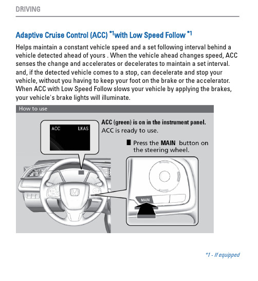
Adaptive Cruise Control (ACC) *1with Low Speed Follow *1Helps maintain a constant vehicle speed and a set following interval behind a vehicle detected ahead of yours . When the vehicle ahead changes speed, ACC senses the change and accelerates or decelerates to maintain a set interval. and, if the detected vehicle comes to a stop, can decelerate and stop your vehicle, without you having to keep your foot on the brake or the accelerator. When ACC with Low Speed Follow slows your vehicle by applying the brakes, your vehicle's brake lights will illuminate.*1 - If equippedn Activating and Setting the Vehicle Speed1.Press the MAIN button. The ACCindicator appears in the multi-information display.2.Accelerate to the desired speed (above 25 mph/40 km/h). Take your footoff the pedal and press the SET/- button to set the speed.n Adjusting the Vehicle SpeedPress the RES/+ button to increasespeed or the SET/- button to decreasespeed. Each time you press the button,the vehicle speed is increased ordecreased by about 1 mph (1.6 km/h). Ifyou keep the button pressed, thevehicle speed increases or decreasesby 5 mph or 5 km/h until you release it.n Adjusting the Vehicle DistancePress the Interval button to change the following interval. Each time you press the button, the setting cycles through extra long, long, middle, and short.n During OperationIf a vehicle is detected ahead of youwhen ACC is turned on, the systemmaintains, accelerates, or deceleratesyour vehicle’s set speed to keep thevehicle’s set following interval from thevehicle ahead.If a vehicle detected ahead of youslows down abruptly, or if anothervehicle cuts in front of you, a beepsounds and BRAKE appears on the driver information interface to alert you .ACC has limited braking capability.When your vehicle speed drops below 22 mph (35 km/h), ACC willautomatically cancel and no longer will apply your vehicle’s brakes.n Canceling ACCYou can press the CANCEL button,MAIN button or the brake pedal. TheACC with Low Speed Follow indicatorgoes off.Certain conditions may cause ACC tocancel automatically. When thishappens, appears on the driverinformation interface.Improper use of ACC can lead to a crash.Use ACC only when traveling on open highways in good weather.n Switching to Standard Cruise ControlPress and hold the Interval button for one second.Cruise Mode Selected appears in thedriver information interface for two seconds, and then the mode switches to Cruise. Press and hold the interval button again to switch back to ACC . ACC Mode Selected appears on the driver information interface display for two seconds.。
电磁刹车操作规程
电磁刹车操作规程1 适用范围本规程适用于电磁刹车操作方法及操作过程注意事项等内容和要求。
2 风险提示(1)操作人员应精心操作,协调使用刹车和电磁刹车。
(2)不得将刹车手柄长时间置于闭合位置。
(3)不得使用不符合要求的冷却水。
(4)不得堵塞溢流孔。
(5)不得在无冷却水或冷却风机不运行时使用电磁刹车。
(6)不得在设备运转过程中维护保养。
(7)各旋转部位护罩完好齐全。
(8)检维修时先切断动力源,并进行上锁、挂签、测试。
3 操作内容3.1 启用前检查(1)首次使用前应做绝缘测量,绝缘电阻应大于1MΩ。
(2)检查盘车,刹车转子应转动灵活。
(3)在刹车两侧轴承腔内注入锂基脂。
(4)在牙嵌或齿式离合器的滑动与转动部分注入适量润滑脂。
(5)呼吸孔畅通无油污。
(6)油冷式控制柜内油质良好,油面距离上端盖20mm左右,保证内部电器元件浸入冷却油内。
(7)控制箱各电器元件安装牢固。
(8)司钻控制箱手柄牢固、灵活无卡滞。
(9)保证控制箱与刹车主体接线正确牢固。
(10)风冷式电磁刹车进排风门畅通无阻;风机转动灵活,报警装置完好。
(11)水冷式电磁刹车准备充足的刹车冷却软化水,水压开关及报警装置完好。
3.2 启动(1)闭合电源开关。
(2)检查控制柜内指标灯状态及仪表参数,确认指标正确。
(3)风冷式启动风机,水冷式启动水泵。
3.3 操作与运行(1)在下钻过程中,重量超过30t后要使用电磁刹车,用电磁刹车手柄控制下放速度。
(2)运行中冷水温度与流量应符合要求,轴承升温不大于70℃,轴承处无冷却水渗出;刹车坚固件无松动;冷却风机运转正常,变压器及油冷式控制柜温度正常。
(3)每次下钻前检查维护轴承、牙嵌、离合器、拨叉。
检查控制柜仪表,指标灯指标正常。
(4)及时清除进排风口杂物。
(5)下钻完毕后,风冷刹车应继续通风,刹车冷却后再关闭风机。
(6)停机时关闭电源开关。
汽车碟式刹车分泵调整回位工具使用说明
汽车碟式刹车分泵调整回位工具使用说明一、工具介绍汽车碟式刹车分泵调整回位工具是一种专门用于调整汽车碟式刹车分泵回位的工具。
它由一个手柄和一个可调节的螺丝钉组成。
手柄用于握持,螺丝钉用于调整刹车分泵的回位力度。
二、使用步骤1. 准备工作:首先,确保车辆停在平坦且安全的位置,切断点火开关,拉紧手刹,确保车辆不会滑动。
同时,准备好需要使用的汽车碟式刹车分泵调整回位工具。
2. 定位工具:根据车辆的具体型号和刹车系统的位置,找到刹车分泵的位置。
通常刹车分泵位于发动机舱内,靠近驾驶员侧。
确保可以方便地触及到刹车分泵。
3. 插入工具:将汽车碟式刹车分泵调整回位工具的螺丝钉插入刹车分泵的调整孔中。
要注意,螺丝钉需要与孔内的凹槽相吻合,以确保插入正确。
4. 调整回位力度:握住工具的手柄,顺时针或逆时针旋转螺丝钉,使刹车分泵的回位力度适合实际需要。
要根据实际情况进行调整,避免回位力度过大或过小,以确保刹车分泵的正常工作。
5. 测试刹车:在完成调整后,可以进行简单的刹车测试。
要确保刹车踏板的回位灵敏度和刹车效果符合要求。
如果发现异常情况,应立即停止操作,并检查是否有其他问题存在。
三、注意事项1. 在调整刹车分泵回位力度时,要谨慎操作,避免过度调整或不当操作造成损坏。
2. 在使用工具时,要注意保持手柄的稳定握持,以避免工具脱落或滑动造成伤害。
3. 如果不确定如何正确使用该工具或调整刹车分泵回位力度,建议寻求专业技术人员的帮助或咨询。
结论:汽车碟式刹车分泵调整回位工具是一种简单而实用的工具,它可以帮助我们调整刹车分泵的回位力度,确保刹车系统的正常工作。
在使用工具时,要注意安全操作,并遵循正确的步骤进行调整。
如有任何不确定或需要帮助,建议咨询专业技术人员。
通过正确使用该工具,我们可以更好地维护和保养汽车的刹车系统,确保行驶安全。
碟刹使用手册说明书

INTRODUCTIONMeng Kah Auto Parts Trading Sdn. Bhd. incorporated in the year 1998, with the core business of importing and distributing motorcyc e parts and accessories. With a successful venture, it has created a brand "Racing Boy" to meet the high demand and expectation of its customers. The services include in-house designing, testing, developing and manufacturing of high quality and stylish products.In the year 2013, Racing Boy has again rebranded itself as "RCB" to further solidify as an international name. Today, RCB design and manufacture a full range of accessories that includes rims, absorbers, braking systems, engineparts and handling systems. RCB, a leading international brand.Safety SymbolsIn this manual, mounting intructions and other technical documents, important information concerning safety is distinguished by the following symbols :The Danger Symbol: If not observed, have a high degree of probability that they will cause serious injury or even death.The Warninng Symbol: If not observed, could possibly cause injury.The Caution Symbol: if not observed, could result in damage to the vehicleWarning! Danger!Caution!Danger!This RCB product has been designed to comply with applicable safety standards. Products are not intended to be used di erently from the specific use for which they have been designed and manufactured. Use for any other purpose, or any modification to, or tampering with, the Product can a ect the performance of the Product and may render the Product unsafe. Such modification or improper use wil void the Limited Warranty, and may subject the individual so using the Product to l iabil ity for bodil y injury or property damage to others.This Product is vital to the safe operation of the vehicle on which it is installed, and it is intended to be installed only by a skilled, qualified individual who has been trained and/ or is experienced in the installation and use for which the Product is intended. The installer must be equipped with the proper tools of his trade, and with the knowledge and experience to deal with vehicle repairs. Improper or incorrect installation, whether caused by a failure to faithfully and completely follow these Instructions or otherwise, will void the Limited Warranty and could subject the installer to liability in the event of personal injury or property damage. RCB shall not be liable for any damage or injury caused to or by any person operating a vehicle on which a replacement product has been improperly installed.The used product replaced by this Product must not be installed on any other product. Property damage and personal injury, including death, could result.In this course of replacing the product, and related items such as brake fluid, brake pads, brake shoes, and the like, the installer will be exposed to fluids and parts that may be deemed to be “hazardous waste” under applicable laws, rules and regulations. All such wastes must be handled, recycled and or disposed of in accordance with all applicable laws, rules and regulations. The failure to do so can subject the generator of the hazardous waste to penalties under environmental laws, and could result in bodily injury or property damage to the generator or others.Always check that the brake fluid level in the reservoir is between the minimum and maximum levels indicated on the reservoir. An incorrect level can cause brake fluid leaks or reduced brake system e iciency. Too much or too little brake fluid in the reservoir could cause the brakes not to perform properly, and personal injury, including death, could result.Warning!Warning!To avoid creating a defective installation, avoid sharply striking and/ or damaging the Product, its parts and its components, as this can impair their e iciency and may cause them to malfunction. If necessary, replace any damaged part or component.To avoid injury:• Always wear gloves during disassembly and assembly of components with sharp edges.• Do not allow skin surfaces to make direct contact between the pad and shoe linings since thiscould cause abrasions.• Ensure correct connection of any electrical contacts, checking that the warning lights come on.If they do not, non-operation of the warning lights can cause a reduction in e iciency of thebraking system, or brake signaling failure.Avoid contact of grease and other lubricants with the braking surfaces of the disc and pads as this could a ect the e iciency of the braking system and cause serious physical damage.Caution!Check that the bearing seats are free from dirt. Any dirt present can damage the seats during assembly operations and shorten bearing life.Do not use sharp tools when fitting rubber components, since this can damage them. Be sure to replace damaged components.Every time the discs are changed you should also replace the pads.NoticeThis feature only available for a certain model of motorcycle.REMOVE THE FRONT WHEELRELEASE THE OLD BRAKE DISC• First jack up your motorcycle securely in order to unload the wheel.• Loosen the fastening screws of the caliper.• Move the calliper away from the disc.• Unscrew the nut on the pin and loosen the screws of the fork joint feet, on both sides if present, without taking them out.• Remove the pin keeping the wheel slightly raised to permit extraction of the pin.• Remove the wheel.• Rest the wheel on a rest surface.• Unscrew and remove the disc fastening screws.• Remove the disc to be replaced.• Clean the area where the disc rests on the wheel using a degreasing product.• Hook the caliper or calipers to the vehicle chassis by means of appropriate supports.Warning!Warning!Warning!Securely support the vehicle so that there is no danger of it falling over.Do not apply the brake lever when removing the brake caliper.Notice• Keep any type of magnets (including magnetic pick-up tools, magnetic screwdrivers, etc.) away from the front wheel sensor or front wheel sensor rotor; otherwise, the sensor or rotor may be damaged, resulting in improper performance of the ABS system. • Do not drop the front wheel sensor rotor or subject it to shocks. • If any solvent gets on the front wheel sensor rotor,wipe it o immediately. During all the operations described below, the caliper fluid inlet hose must NOT be disconnected.Caution! Ensure that the solvent does not come into contact with parts of the wheel that could be damaged (rubber and paint). Absorb with paper.REFIT THE FRONT WHEEL • Insert the wheel in the fork joint observing the forward rotation direction indicated on the wheel.• Clean with a damp cloth and lubricate the surface of the pin to facilitate insertion.• Insert the pin keeping the wheel in the correct position with one hand and centring the spacer and the milometer transmission, if provided.• Position the screws of the feet of the fork joint, on both sides if present, only tightening them far enough to keep them in position.• Tighten the nut on the pin to torque prescribed by the vehicle manufacturer.• Install the front caliper to the fork joint. • Compress the suspension to bed the fork joint.• Tighten the screws of the fork joint foots usinga torque wrench, applying the torque prescribed by vehicle manufacturer.FIT THE FRONT BRAKE DISCWarning! Always replace badly corroded or damaged fastening bolts with new ones.• Fit the new brake disc. • Use torque wrench to tighten the fasteningbolts to the torque specified by the vehiclemanufacturer, in diagonally opposite sequence.FITT THE REAR BRAKE DISC • Clean the supporting surfaces, all the seats and all the components involved in the refitting operation using a degreasing product.• Position the sprocket on the rear wheel.• Re-tighten the sprocket fastening screws, if provided, applying the tightening toque prescribed by the vehicle manufacturer.Warning! Ensure that the solvent does not come into contact with parts of the wheel that could be damaged (rubber and paint). Absorb with paper.• Position the brake disc to the rim. • Insert the new fastening screws and tighten themwith a torque wrench.REMOVE THE REAR WHEEL Notice• Keep any type of magnets (including magnetic pick-up tools, magnetic screwdrivers, etc.) away from the front wheel sensor or front wheel sensor rotor; otherwise, the sensor or rotor may be damaged, resulting in improper performance of the ABS system. • Do not drop the rear wheel sensor rotor or subject it to shocks. • If any solvent gets on the rear wheel sensor rotor, wipe it o immediately. • Stand the vehicle on a level surface.Warning!Securely support the vehicle so that there is no danger of it falling over.Place the vehicle on a center stand so that the rear wheel is elevated.TIP • Unscrew the nut on the pin.• Remove nut and washer.• Remove the pin keeping the wheel slightly raised to permit extraction of the pin.• Remove the spacer.• Gently push the wheel towards the vehicle.• Slide the chain out of the sprocket resting it on its side.• Remove the wheel.• Release the old brake disc. Refer to “Front Brake Disc ” on page 5• Reposition the caliper on the brake disc.• If the pads obstruct insertion of the caliper on thedisc, press firmly with your hands on the pads to retract the pistons.• Tighten the fastening screws of the caliper of calipers, applying the tightening torque prescribed by the vehicle manufacturer.• Check the brake fluid level and top up if necessary with new fluid in compliance with the recommendations of the vehicle manufacturer.• Remove the vehicle from the stands.• Repeatedly operate the brake lever/ pedal until the normal resistance has been restored and check braking e iciency.REFIT THE REAR WHEEL• Slightly lubricate the surface of the pin to facilitate insertion.• Insert the wheel into the fork.• Reposition the caliper on the brake disc.• Gently push the wheel towards the vehicle.• Reposition the chain on the sprocket .• Correctly reposition the spacer.• Insert the pin, checking that it fits into the hole provided on the caliper supporting bracket and that the caliper is correctly positioned in its seat on the fork.• Check correct positioning of the pin in its seat on the fork.• Correctly reposition the washer and nut.• Position a shim (e.g. a screwdriver) between the chain and the sprocket.• Rotate the wheel far enough to block the shim between the chain and the sprocket.This operation eliminates the need to tension the chain.• Tighten the nut on the pin to tightening torque prescribed by the vehicle manufacturer.• Rotate the wheel in the opposite direction and remove the shim.• Check correct tensioning of the chain according to the directions provided by the vehicleCaution!REAR WHEELCHECKING THE BRAKE DISC Warning!Never attempt to make any repairs to the disc.Measure The Brake Disc RunoutMeasure The Brake Disc ThicknessDamage/galling Replace • Place the vehicle on suitable stand to make sure the wheel to be measured is elevated. • Remove the brake caliper.• Hold the dial gauge at a right angle against the brake disc surface.• Measure the runout 1.5mm (0.06in) below the edge of the brake disc.• Brake disc runout limit: 0.15mm (0.0059in)• Out of specification replace the brake disc.• Measure the brake disc thickness at a few di erent l ocations.• Out of specification Replace.While working on the brakes, make sure that no grease, paste, brake fluid or other chemicals come into contact with the surface of the brake pads.In order to achieve optimum braking performance with a new brake disc, always replace the brake pads at the same time.Warning!INSPECTION & MAINTENANCES-SERIES ALLOY DISC00– Floating Brake Disc– Alloy 7075 (Aircraft Grade)– Enchance durability level– Improve Safety & Performance– Provide Effective Braking Power – Anodised anti Rust– Better Heat DissipationE-SERIES STEEL DISC– High Quality Buttons– Heat treated Stainess Steel– Enchance durability level– Improve Safety & Performance– Provide Effective Braking Power – Better Heat DissipationMODEL INFORMATION。
- 1、下载文档前请自行甄别文档内容的完整性,平台不提供额外的编辑、内容补充、找答案等附加服务。
- 2、"仅部分预览"的文档,不可在线预览部分如存在完整性等问题,可反馈申请退款(可完整预览的文档不适用该条件!)。
- 3、如文档侵犯您的权益,请联系客服反馈,我们会尽快为您处理(人工客服工作时间:9:00-18:30)。
DWS40电磁涡流刹车使用说明书上海申通石油机械厂有限公司一、性能及说明DWS40型涡流刹车用作钻深为4000米的海洋或陆地钻机的辅助刹车,既可绞车成套供应,也可为矿场已经使用的钻机配套作为单独部件供应。
1、技术规范最大扭矩 60000N.m钻井深度 4000m作用原理感应涡流制动线圈个数 4每个线圈额定电阻(20°C时) 5.39Ω线圈绝缘等级H级励磁功率 12KW励磁电流(两串两并时)40A需用冷却水量285L/min最大出水温度(当进水温度42°C时) 72°C重量 6500kg二、结构电磁涡流刹车由刹车主体、可控硅整流装置及司钻开关等三部分组成。
1、刹车主体它由两个基本部分组成,如图一所示。
其一为静止部分,称为定子;其二为转动部分,称为转子。
在定子与转子之间有一定的气隙,称为工作气隙,电磁涡流刹车的刹车主体采用外电枢结构的型式,也就是说,其转子在定子外面旋转。
刹车的定子由磁极和激磁线圈构成。
磁极是磁路的一部分,采用电工钢制成,这种材料的导磁系数高,矫顽力小,以满足下钻时有用制动扭矩大,而起空吊卡时无用制动扭矩小的要求。
激磁线圈是刹车的电路部分,工作时通以直流电流,它固定于磁极上,与磁极组成一个整体成为定子。
刹车在运行时要产生大量的热量,因此激磁线圈采用了耐高温的电磁线与相应的绝缘材料,以保证线圈在高温下仍具有良好的绝缘性能。
图一电磁涡流刹车结构示意图1. 端盖2. 转子3. 机座4. 定子5. 激磁线圈6.上呼吸器7.下呼吸器刹车的转子通过齿式离合器与绞车滚筒轴相联,由绞车滚筒驱动,与滚筒同速旋转。
转子既是磁路的一部分,又是电路的一部分,采用电工钢制成。
它和定子磁极、工作气隙构成刹车的完整磁路。
2.可控硅整流装置:它由整流变压器和可控硅半控桥式整流电路组成。
用以将钻机交流发电机或交流电网供给的交流电压变成可调直流电压,给激磁线圈通以可调直流电流。
考虑到使用电磁涡流刹车进行下钻作业时,其下钻速度的调整精度、调节系统的稳定性以及过渡过程动态品质方面的指标都要求不高,因此采用比较简单的闭环调节系统即可满足钻井工艺的要求。
通过调节激磁线圈的直流电流,便可调节刹车的制动扭矩,从而改变钻具的下放速度。
3.司钻开关:它实际上是一台可调的差动变压器,由铁芯、线圈、调节机构等部分组成。
将铁芯位置的变化转换成交流信号电压的变化,经桥式整流作为给定信号电压,去控制可控硅的导通角,达到改变直流电压,从而改变激磁线圈直流电流,改变制动扭矩,调节滚筒转速的目的。
壳体两侧装有四个排除不锈钢护罩内冷凝水的呼吸器及两个润滑轴承的黄油嘴。
")锥度为8:77ft。
涡流刹车输出轴端直径为190.52mm(71/2刹车的外形尺寸为:长度1201mm(47")宽度1514mm(59")高度1514mm(59")三、冷却系统涡流刹车与绞车的滚筒共用一个水冷却系统,由一个水泵供应冷却水,流经刹车的冷却水返回一个容积为16m3的水箱以便散热,刹车需用的冷却水量为285L/min确保涡流刹车的进出水温度在规定的范围内。
冷却水系统的流程图如图二所示。
水质要求含有较低的矿物质(PH值不超过7~7.5),与内燃机水套内的水质要求相近,如果水质不合要求,则需进行化学处理,当刹车用于海洋时,也可以装置专门的海水冷却器。
四、安装说明刹车本身带有支架,可直接安装于钻深为4000m的国产ZJ32、40L型钻机的绞车上,如果应用于其他钻机则应更换支架。
刹车轴端装有齿式离合器与滚筒相联接,请注意此处不需要也不允许用单向离合器,因刹车转子需要与滚筒一起在两个方向同步回转以保证转子能通过冷却水得到冷却。
从刹车排出的冷却水经过一个漏斗返回水箱,漏斗与排水接头稍离一段距离以保证排水流畅。
当无回水泵时,水箱安装的位置应与涡流刹车内的冷却水有足够的水位差,使冷却水能自流返回,刹车两侧各有一个1¼"溢流管,此管不允许堵塞,以防止内腔水位上升致使轴承锈蚀。
应当指出,电磁涡流刹车的冷却水必须在溢流管有一定的水流出时为适宜,从而保证冷却水在涡流刹车内有一定的水位高度。
否则会造成涡流刹车过热,甚至烧坏线圈,导致涡流刹车损坏而无法正常工件。
五、作用原理电磁涡流刹车又称电磁涡流制动器。
它是一种将钻具下钻时产生的巨大机械能转换成电能,又将电能转换为热能的非摩擦式能量转换装置。
这种能量的转换及强有力的制动过程,是通过电磁感应原理完成的,而不是通过摩擦式的或其他形式的磨擦付完成的,没有任何磨损件。
制动时产生的巨大热量,通过水介质进行吸收与交换。
当刹车工作时,在它的激磁线圈内通入直流电流,于是在转子与定子之间便有磁通相链,使转子处在磁场闭合回路中。
磁场所产生的磁力线通过磁极→气隙→电枢→气隙→磁极。
形成一个闭合回路。
如图三所示,下钻时,绞车滚筒旋转,通过离合器驱动转子以相同转速在定子所建立的磁场内旋转。
在这个磁场中,磁力线在磁级的齿部(凸极部分)分布较密,而在磁极的槽部(齿间部分)分布较稀,因此随着转子与定子的相对运动,转子各点上的磁通便处于不断重复的变化之中。
换句话说,转子沿工作气隙的圆周上的因磁极的齿部和槽部的磁导不等,在空间建立脉动磁场,根据电磁感应定律,转子上便产生感应电势,在这个感应电势作用下,转子中产生涡流。
涡流与定子磁场相互作用产生电磁力,力的方向由左手定则确定,该力沿转子的切线方向,并且与转子旋转方向相反。
这个力对转子轴心形成的转矩称为电磁转矩,也就是电磁涡流刹车阻止滚筒旋转的制动扭矩。
司钻通过调节司钻开关手柄位置,便调节了激磁电流的大小,改变了制动转矩的大小,从而达到了控制钻具下放速度的目的。
图三电磁涡流刹车工作原理示意图六、安装与调试1、电磁涡流刹车开箱后,首先检查刹车主体、可控硅整流装置及司钻开关三个部件是否完好无损。
转动刹车主体的转子是否转动自如,齿式离合器操纵是否灵活。
可控硅整流装置的元件与接线是否松动,元器件是否有损坏。
司钻开关的操纵手柄转动是否灵活。
在外观检查合格的基础上接着进行安装、接线和调试。
角度误差的调整水平误差的调整图四电磁涡流刹车轴与滚筒轴的找正2.将涡流刹车主体吊装到绞车底座上,安放在原水刹车的位置。
刹车轴与绞车滚筒轴之间用齿式离合器联接。
安装时必须保证涡流刹车轴与绞车滚筒轴轴线严格找正,其同轴度误差不得大于0.25毫米。
找正时可按图四所示方法,用百分表检查角度误差和水平偏置误差,借助涡流刹车底板上的四个顶丝,在刹车与底座间用垫片进行调整。
在现场安装调整时,如果没有百分表,可用钢板尺和塞规进行检验,也可用指针靠在离合器端面及径向在圆周的四个方向检查其跳动量。
如果涡流刹车轴与绞车滚筒轴中心没有找正或误差很大,将造成轴承负荷增加,导致轴承早期磨损直至损坏报废。
除了保证涡流刹车中心高与绞车滚筒中心高保持一致外,还必须保证离合器处于分离状态时其间有15~19毫米的间隙。
安装后的离合器应能灵活移动,保证离合器在挂合与分离时操作自如,没有任何卡阻现象。
3.将可控硅整流装置稳妥地安装在钻机配电房或压风机房内,切不可露天安放,以防受潮受热而损坏。
若安装处振动较为严重,应采取防振措施,如垫以橡皮等。
4.将司钻开关(司钻控制器)安装在绞车气控箱上或司钻操作方便的位置,便于司钻操纵,并用螺栓固定,不得松动。
司钻开关应操作灵活,并保证自动复零与断电。
5.接线:严格按照电气原理图要求进行接线。
在接线之前,先用500伏兆欧表检查涡流刹车激磁线圈对地绝缘电阻,其值必须大于1 MΩ,一般正常情况下测得的绝缘电阻为无限大。
6.电路调试(1) 按电气原理图和接线图要求,严格检查接线是否正确无误,确认无误后方可接通电源,进行调试。
(2) 可控硅整流装置直流输出端S1( + )、S2(-)的负载先不接涡流刹车激磁线圈,先接500瓦、220伏白炽灯泡作假负载。
(3) 接通控制电源、扳动开关K1。
主回路断开,交流接触器ZC断开。
a. 观察指示灯HD(红色)是否变亮,检查交流输入电压220伏或380伏是否正常。
b. 用示波器观察电容C11两端是否出现锯齿波。
c. 用双线示波器或普通示波器观察触发脉冲波形,将探头分别接触G 1—Z11、G2—X22,脉冲波形应正常,脉冲应不丢失。
(4) 接通主回路电源,揿下按扭QA1,接触器ZC接通,指示灯LD(绿色)变亮。
a. 用双线示波器观察直流输出端S1( + )、S2(-)之间以及可控硅控制极与阴极间的波形,此时应观察到触发脉冲波形和直流输出波形。
b. 将面板上的给定信号开关扳向“内”(即本机给定)。
调节给定电位器W1,由零逐渐增大,主回路的直流输出电压随着给定信号的增大而增大,(从直流电压表和示波器以及假负载灯炮可以清楚看到输出电压的变化)。
c. 将面板上的给定信号开关扳向“外”(即司钻开关给定)。
调节司钻开关(即司钻控制器)的手柄,即调节差动变压器的铁芯位移,也就调节了给定信号电压,主回路的直流输出电压同样随着给定信号的变化而变化。
从直流电压表,灯炮以及示波器可以清楚地看到这种变化。
在调节过程中注意观察系统是否稳定。
(5) 将可控硅整流装置直流输出端S1( + )、S2(-)接入涡流刹车激磁线圈,调试用的假负载220伏、500瓦白炽灯炮仍并联在直流输出端S1( + )、S2(-),不必拆除。
使给定信号为零,然后分别接通控制电源K1和主回路ZC调节给定信号电压W1,随着给定信号的逐渐增加,涡流刹车激磁线圈的电流逐渐从零增大到最大值 40安,从直流电压表、电流表白炽灯炮以及接在直流输出端的示波器波形可以清楚地观察到直流电压、直流电流的变化。
在调试过程中分别进行“内控”与“外控”调试,并随时注意系统是否稳定,若系统不够稳定,呈现振荡,可调节反馈电位器使之稳定。
至此,电磁涡流刹车的安装与调试已经完成,即可投入运转。
需要注意的是,刹车在每次搬家后,必须重复上述(5)接线和(6)电路调试的内容,不可省略,也不可麻痹大意。
七、故障的排除1、轴承的损坏——转子与定子表面擦碰,导致磁极间短路。
(1)产生的原因:①与绞车滚筒轴不同轴度太大。
②轴承缺乏适当地润滑。
③刹车腔内水位过高使轴承密封工作恶化。
A、进水排量过大。
B、排水管被堵塞。
C、排水口背压过高。
(2)排除方法:①调整轴的位置②按轴承保养守则进行保养。
③将排水控制在280L/min,排水管直径不得小于3",另外也不能产生刹车内腔与水箱的位置差不够或返回水箱的排出水管线过长的现象;刹车排出管不要连接在漏斗上。
2、空气隙恶化——空气和铁的氧化物是不良的导磁体,稍微增加空气隙或表面沉积锈蚀层将会大大减少穿过转子和磁极间的磁通量。
(1)、产生的原因:①使用了高含盐量或高PH值(7~7.5)的冷却水造成转子和磁极表面有大量的锈蚀层和水垢层。