基于51单片机 DS1302 LCD1602数字时钟显示
DS1302+LCD1602显示程序
/*头文件*/
#include <reg52.h>
#include <intrins.h>
#define uint unsigned int
#define uchar unsigned char
#define nop() _nop_()
sbit lcd_rs_port = P2^0; /*定义LCD控制端口*/
/****************************************************************
程序名称: LCD1602显示时间
函 数 名:W1302()
功 能:往DS1302写入数据
说 明:先写地址,后写命令/数据 (内部函数)
调 用:RTInputByte() , RTOutputByte()
入口参数:ucAddr: DS1302地址, ucData: 要写的数据
返 回 值:无
RTInputByte(ucAddr); /* 地址,命令 */
ucData = RTOutputByte(); /* 读1Byte数据 */
T_CLK = 1;
T_RST = 0;
return(ucData);
uchar data time_data_buff[7]={0x00,0x00,0x09,0x01,0x01,0x04,0x09};/*格式为: 秒 分 时 日 月 星期 年 */
uchar data lcd1602_line1[]={" 2000/00/00 000"};
uchar data lcd1602_line2[]={" 00:00:00 "};
用DS1302+LCD1602制作的时钟

{
uchar i,*p;
p = RTC_RADD; //地址传递
for(i = 0 ; i < 7 ; i++) //分7次读取 秒分时日月周年
{
SJ[i] = Read_Ds1302(*p);
p++;
}
}
/*************************************************/
}
/*****************************************************/
/****LCD定位******************************************/
void LOCATE(uchar H , uchar L)
{
if(H == 1) //如果是第一行
{
LCD_RS = rs; //写指令/数据选择:低电平写指令,高电平写数据
LCD_RW = 0; //读写选择:低电平写,高电平读
LCD_E = 0; //关使能
LCD_DAT = c_d; //把指令/数据写入P1口
delay(5); //延时5ms
{
if(SDA)
temp |= 0x80; //每次传输低字节
SCK = 0;
temp>>=1; //右移一位
_nop_();
_nop_();
_nop_();
SCK = 1;
}
RST = 0;
_nop_(); //以下为DS1302复位的稳定时间
基于DS1302和LCD1602的可调数字钟
学习情境2-可调式数字钟之基于DS1302和LCD1602的可调数字钟☆点名,复习1、DS1302的引脚及其功能,以及DS1302与单片机的硬件连接?2、如何对DS1302读写数据,如何得到DS1302的时钟?☆新课讲授2.3 基于DS1302与LCD1602设计的可调数字钟上堂课程我们学会了使用DS1302,知道了如何在单片机系统中的连接,也详细的学习了如何得到DS1302的时钟,并且我们使用了16个数码管把年月日和时分秒实时地显示出来。
但数码管的显示毕竟有其自身的缺陷,现在在工业控制的各个环节,都使用液晶进行人机联系。
在日常生活中,我们对液晶显示器并不陌生。
液晶显示模块已作为很多电子产品的通用器件,如在计算器、万用表、电子表及很多家用电子产品中都可以看到,显示的主要是数字、专用符号和图形。
在单片机的人机交流界面中,一般的输出方式有以下几种:发光管、LED 数码管、液晶显示器。
发光管和LED数码管比较常用,软硬件都比较简单,在单片机系统中应用液晶显示器作为输出器件有以下几个优点:(1)显示质量高,由于液晶显示器每一个点在收到信号后就一直保持那种色彩和亮度,恒定发光,而不像阴极射线管显示器(CRT)那样需要不断刷新新亮点。
因此,液晶显示器画质高且不会闪烁。
(2)数字式接口,液晶显示器都是数字式的,和单片机系统的接口更加简单可靠,操作更加方便。
(3)体积小、重量轻,液晶显示器通过显示屏上的电极控制液晶分子状态来达到显示的目的,在重量上比相同显示面积的传统显示器要轻得多。
(4)功耗低,相对而言,液晶显示器的功耗主要消耗在其内部的电极和驱动IC上,因而耗电量比其它显示器要少得多。
2.3.1 LCD1602技术资料2.3.1.1 液晶显示简介1、液晶显示原理:液晶显示的原理是利用液晶的物理特性,通过电压对其显示区域进行控制,有电就有显示,这样即可以显示出图形。
液晶显示器具有厚度薄、适用于大规模集成电路直接驱动、易于实现全彩色显示的特点,目前已经被广泛应用在便携式电脑、数字摄像机、PDA移动通信工具等众多领域。
51单片机,DS1302时钟,1602显示,可调时钟剖析
基于proteus的51单片机仿真实例八十一、实时时钟芯片DS1302应用实例1、DS1302引脚排列:如下图引脚说明:1)Vcc1:后备电源,VCC2:主电源。
在主电源关闭的情况下,也能保持时钟的连续运行。
DS1302由Vcc1或Vcc2两者中的较大者供电。
当Vcc2大于Vcc1+0.2V时,Vcc2给DS1302供电。
当Vcc2小于Vcc1时,DS1302由Vcc1供电。
2)X1、X2:振荡源,外接32.768kHz 晶振。
3)RST:复位/片选线,通过把RST输入驱动置高电平来启动所有的数据传送。
RST输入有两种功能:首先,RST接通控制逻辑,允许地址/命令序列送入移位寄存器;其次,RST提供终止单字节或多字节数据的传送手段。
当RST为高电平时,所有的数据传送被初始化,允许对DS1302进行操作。
如果在传送过程中RST置为低电平,则会终止此次数据传送,I/O引脚变为高阻态。
上电运行时,在Vcc>2.0V之前,RST必须保持低电平。
只有在SCLK为低电平时,才能将RST置为高电平。
4)I/O为串行数据输入输出端(双向)。
5)SCLK为时钟输入端。
2、DS1302的控制字节DS1302 的控制字如下图所示。
控制字节的最高有效位(位7)必须是逻辑1,如果它为0,则不能把数据写入DS1302中,位6如果为0,则表示存取日历时钟数据,为1表示存取RAM数据;位5至位1指示操作单元的地址;最低有效位(位0)如为0表示要进行写操作,为1表示进行读操作,控制字节总是从最低位开始输出。
3、数据输入输出(I/O)在控制指令字输入后的下一个SCLK时钟的上升沿时,数据被写入DS1302,数据输入从低位即位0开始。
同样,在紧跟8位的控制指令字后的下一个SCLK脉冲的下降沿读出DS1302的数据,读出数据时从低位0位到高位7。
DS1302的寄存器DS1302有12个寄存器,其中有7个寄存器与日历、时钟相关,存放的数据位为BCD码形式,其日历、时间寄存器及其控制字见数据手册。
DS1302实时时钟模块,1602显示
/******************* 说明:**************************将实时时钟数据通过LCD1602 显示基于51 单片机**************************************************/#include <reg52.h>#include <intrins.h>#define uchar unsigned char#define uint unsigned int uchar dis_time_buf[16]={0};//LCD1602 引脚定义// 采用8 位并行方式,DB0~DB7 连接至LCDDATA0~LCDDATA7sbit RS=P2A0;sbit RW=P2A1;sbit CS=P2A2;#define LCDDATA P0//DS1302 引脚定义sbit RST=P1A3;sbit IO=P1A2;sbit SCK=P1A1;//DS1302 地址定义#define ds1302_sec_add 0x80 // 秒数据地址#define ds1302_min_add 0x82 // 分数据地址#define ds1302_hr_add 0x84 // 时数据地址#define ds1302_date_add 0x86 // 日数据地址#define ds1302_month_add 0x88 // 月数据地址#define ds1302_day_add 0x8a // 星期数据地址#define ds1302_year_add 0x8c // 年数据地址#define ds1302_control_add 0x8e // 控制数据地址#define ds1302_charger_add 0x90#define ds1302_clkburst_add 0xbe// 初始时间定义uchar time_buf[8] = {0x20,0x10,0x06,0x01,0x23,0x59,0x55,0x02};// 初始时间2010年6月1号23 点59 分55 秒星期二// 功能:延时 1 毫秒// 入口参数:x// 出口参数:无//说明:当晶振为12M时,j<112 ;当晶振为11.0592M时,j<122void Delay_xms(uint x){uint i,j;for(i=0;i<x;i++)for(j=0;j<112;j++);// 功能:12us 延时//STC89C52为1T单片机,即1个时钟/机器周期,速度为AT89C52的12倍void Delay_xus(uint t){for(;t>0;t--){_nop_();}}//控制LCD写时序void LCD_en_write(void){CS=1;Delay_xus(20);CS=0;Delay_xus(20);}// 写指令函数void Write_Instruction(uchar command){RS=0;RW=0;CS=1;LCDDATA=command;LCD_en_write();// 写入指令数据}// 写数据函数void Write_Data(uchar Wdata){RS=1;RW=0;CS=1;LCDDATA=Wdata;LCD_en_write();// 写入数据}// 字符显示初始地址设置void LCD_SET_XY(uchar X,uchar Y){uchar address;if(Y==0) address=0x80+X;//Y=0, 表示在第一行显示,地址基数为0x80elseaddress=0xc0+X;//Y 非 0 时,表时在第二行显示,地址基数为 0xC0 Write_Instruction(address);// 写指令,设置显示初始地址}//在第X 行Y 列开始显示 Wdata 所对应的单个字符 void LCD_write_char(uchar X,uchar Y,uchar Wdata){LCD_SET_XY(X,Y)写 地址Write_Data(Wdata);// 写入当前字符并显示}// 清屏函数 void LCD_clear(void){Write_Instruction(0x01); Delay_xms(5);}// 显示屏初始化函数 void LCD_init(void){Write_Instruction(0x38); // 8bit interface,2line,5*7dotsDelay_xms(5);Write_Instruction(0x38); Delay_xms(5);Write_Instruction(0x38);Write_Instruction(0x08); //关显示,不显光标,光标不闪烁 Write_Instruction(0x01); //清屏 Delay_xms(5);//Write_Instruction(0x05); //Write_Instruction(0x06);//Write_Instruction(0x07);Delay_xms(5); // 写一字符,整屏右移 // 写一字符,整屏显示不移动// 写一字符,整屏左移//Write_Instruction(0x0B); Write_Instruction(0x0C);//Write_Instruction(0x0D); //Write_Instruction(0x0E); //Write_Instruction(0x0F); } //DS1302 初始化函数 void ds1302_init(void){Write_Instruction(0x04); // 写一字符,整屏显示不移动 // 关闭显示(不显示字符,只有背光亮) // 开显示,光标、闪烁都关闭// 开显示,不显示光标,但光标闪烁 // 开显示,显示光标,但光标不闪烁}//向DS1302写入一字节数据void ds1302_write_byte(uchar addr, uchar d){uchar i; RST=1;// 启动 DS1302 总线// 写入目标地址: addraddr = addr & 0xFE; // 最低位置零,寄存器 0 位为 0 时写,为 1 时读 for (i = 0; i < 8; i ++) {if (addr & 0x01) {IO=1;}else {IO=0;}SCK=1; //产生时钟 SCK=0;addr = addr >> 1;}// 写入数据: dfor (i = 0; i < 8; i ++) {if (d & 0x01) {IO=1;}else {IO=0;}SCK=1; // 产生时钟 SCK=0; d = d >> 1;}RST=O;〃停止 DS1302 总线}//从DS1302读出一字节数据uchar ds1302_read_byte(uchar addr) {uchar i,temp; RST=1;// 启动 DS1302 总线// 写入目标地址: addr addr = addr | 0x01;// 最低位置高,寄存器 0 位为 0 时写,为 1 时读for (i = 0; i < 8; i ++) {RST=0; SCK=0;//RST 脚置低 //SCK 脚置低if (addr & 0x01) { IO=1;}else { IO=0;}SCK=1;SCK=0;addr = addr >> 1;}// 输出数据:tempfor (i = 0; i < 8; i ++) { temp = temp >> 1; if (IO) {temp |= 0x80;}else {temp &= 0x7F; }SCK=1;SCK=0;}RST=0;//停止DS1302 总线return temp;}//向DS302写入时钟数据void ds1302_write_time(void) {ds1302_write_byte(ds1302_control_add,0x00); // 关闭写保护ds1302_write_byte(ds1302_sec_add,0x80); // 暂停时钟//ds1302_write_byte(ds1302_charger_add,0xa9); // 涓流充电ds1302_write_byte(ds1302_year_add,time_buf[1]); // 年ds1302_write_byte(ds1302_month_add,time_buf[2]); //月ds1302_write_byte(ds1302_date_add,time_buf[3]); // 日ds1302_write_byte(ds1302_hr_add,time_buf[4]); // 时ds1302_write_byte(ds1302_min_add,time_buf[5]); // 分ds1302_write_byte(ds1302_sec_add,time_buf[6]); // 秒ds1302_write_byte(ds1302_day_add,time_buf[7]); // 周ds1302_write_byte(ds1302_control_add,0x80); //打开写保护}//从DS302读出时钟数据void ds1302_read_time(void){time_buf[1]=ds1302_read_byte(ds1302_year_add); // 年time_buf[2]=ds1302_read_byte(ds1302_month_add); // 月time_buf[3]=ds1302_read_byte(ds1302_date_add); // 日time_buf[4]=ds1302_read_byte(ds1302_hr_add); // 时time_buf[5]=ds1302_read_byte(ds1302_min_add); // 分time_buf[6]=(ds1302_read_byte(ds1302_sec_add))&0x7f;// 秒,屏蔽秒的第7 位,避免超出59time_buf[7]=ds1302_read_byte(ds1302_day_add); // 周}void Display(void){LCD_write_char(3,0,dis_time_buf[0]+'0');LCD_write_char(4,0,dis_time_buf[1]+'0');LCD_write_char(5,0,dis_time_buf[2]+'0');LCD_write_char(6,0,dis_time_buf[3]+'0');LCD_write_char(7,0,'/');LCD_write_char(8,0,dis_time_buf[4]+'0');LCD_write_char(9,0,dis_time_buf[5]+'0');LCD_write_char(10,0,'/');LCD_write_char(11,0,dis_time_buf[6]+'0');LCD_write_char(12,0,dis_time_buf[7]+'0');LCD_write_char(15,0,dis_time_buf[14]+'0'); // 第 2 行显示LCD_write_char(3,1,dis_time_buf[8]+'0');LCD_write_char(4,1,dis_time_buf[9]+'0');LCD_write_char(5,1,':');LCD_write_char(6,1,dis_time_buf[10]+'0');LCD_write_char(7,1,dis_time_buf[11]+'0');LCD_write_char(8,1,':');LCD_write_char(9,1,dis_time_buf[12]+'0');LCD_write_char(10,1,dis_time_buf[13]+'0');}// 定时器中断函数void Timer2() interrupt 5// 定时器 2 是 5 号中断{static uchar t;TF2=0;t++;if(t==4) // 间隔200ms(50ms*4) 读取一次时间{t=0;ds1302_read_time(); // 读取时间dis_time_buf[0]=(time_buf[0]>>4); // 年dis_time_buf[1]=(time_buf[0]&0x0f);dis_time_buf[2]=(time_buf[1]>>4);dis_time_buf[3]=(time_buf[1]&0x0f);dis_time_buf[4]=(time_buf[2]>>4); // 月dis_time_buf[5]=(time_buf[2]&0x0f);dis_time_buf[6]=(time_buf[3]>>4); // 日dis_time_buf[7]=(time_buf[3]&0x0f);dis_time_buf[14]=(time_buf[7]&0x07); // 星期// 第 2 行显示dis_time_buf[8]=(time_buf[4]>>4); // 时dis_time_buf[9]=(time_buf[4]&0x0f);dis_time_buf[10]=(time_buf[5]>>4); // 分dis_time_buf[11]=(time_buf[5]&0x0f);dis_time_buf[12]=(time_buf[6]>>4); // 秒dis_time_buf[13]=(time_buf[6]&0x0f);}}// 定时器 2 初始化void Init_timer2(void){RCAP2H=0x3c;〃赋T2初始值0x3cb0,溢出20次为1秒,每次溢出时间为50ms RCAP2L=0xb0;TR2=1; //启动定时器 2ET2=1; // 打开定时器 2 中断EA=1; // 打开总中断}// 主函数void main(void){Delay_xms(50);// 等待系统稳定LCD_init(); //LCD 初始化LCD_clear(); // 清屏ds1302_init(); //DS1302 初始化Delay_xms(10);ds1302_write_time(); // 写入初始值Init_timer2(); // 定时器 2 初始化while(1){Display();}。
基于LCD1602和DS1302的时间显示程序

/*========================================================== ==使用1602液晶显示DS1302+S51时钟+温度显示zhaojun 2007/06/29=========================================================== ===声明:1. 1602驱动程序照搬明皓的,非常好用2. DS1302驱动程序是参考网友修改而来NS1602R(16*2)模拟口线接线方式连接线图:---------------------------------------------------| LCM-----51 | LCM-----51|LCM------51 || ----------------------------------------------- || DB0-----P0.0 | DB4-----P0.4 | RS-------P2.0 || DB1-----P0.1 | DB5-----P0.5 | RW-------P2.1 || DB2-----P0.2 | DB6-----P0.6 | E--------P2.2 || DB3-----P0.3 | DB7-----P0.7 | VLCD接1K电阻到GND |---------------------------------------------------DS1302 接线图Vcc2 CLK I/O /RST| | | |---------------| 8 7 6 5 || DS1302 || || 1 2 3 4 |---------------| | | |VCC1 GND1. 脚接+5V 2,3. 脚32768HZ晶振4. 脚接地5. 脚接S51的P1.2 6. 脚接S51的P1.1 7. 接S51的P1.08. 脚接后备电源,可以接老计算机主板上的3.6V电池,也可以通过二级管隔离接一个大容量电解电容电压在2.5V以上即可维持按键说明:1. 共三个键,低电平有效2. P1.4 和P1.5 同时按:初始化3. P1.6 端口按键:选择要调整的项目4. P1.5 端口按键:增加;P1.4端口按键:减少[注:AT89S51使用12M晶振]源代码:=================定义与申明=========================================================== ==*/#include "regx51.h"#include "string.h"#include "intrins.h"#define uchar unsigned char#define uint unsigned inttypedef unsigned char byte;typedef unsigned int word;//*********** 1602引脚定义引脚#define LCM_RS P2_0 // 数据/命令选择信号#define LCM_RW P2_1 // 读/写选择信号#define LCM_E P2_2 // 使能信号//*********** DS1302 时间显示定义部分sbit T_CLK=P1^0; //串行时钟输入sbit T_IO =P1^1; //串行数据端口sbit T_RST=P1^2; //复位端口//*********** 18B20温度显示定义部分sbit DQ=P3^3; //18B20 接P33口sbit ACC0=ACC^0;sbit ACC7=ACC^7;#define LCM_Data P0 //显示数据端口#define Busy 0x80 //用于检测LCM状态字中的Busy标识uchar id,timecount; //全局变量bit flag,sflag; //flag是时钟冒号闪烁标志,sflag是温度负号显示标志bit sec,min,hour,year,mon,day,weekk; //闪烁标志位//*********************函数申明void Disp_line1(void); // 显示屏幕第一行void Disp_line2(void); // 显示屏幕第二行void id_case1_key(); // id为1时的下一级选择void Set(uchar,uchar); // 根据选择调整相应项目void RTInputByte(uchar); /* 输入1Byte */uchar RTOutputByte(void); /* 输出1Byte */void W1302(uchar, uchar); // 向DS1302写入一个字节uchar R1302(uchar); // 从DS1302读出一个字节void Set1302(uchar * ); // 设置时间//******* 1602LCD驱动********************************************************** void WriteDataLCM(uchar WDLCM); //写数据void WriteCommandLCM(uchar WCLCM,BuysC); //写指令uchar ReadStatusLCM(void); //读状态void LCMInit(void); //LCM初始化void DisplayOneChar(uchar X, uchar Y, uchar DData); //按指定位置显示一个字符void DisplayListChar(uchar X, uchar Y, uchar code *DData); //按指定位置显示一串字符void Delay5Ms(void); //5ms延时void Delay400Ms(void); //400ms延时Read_Temperature(char,char);//温度显示void mychar(void); //显示自定义字符void adjust_res(char res); //res 分别等于0x1f, 0x3f, 0x5f 温度读数分辨率分别对应// 0.5, 0.25, 0.125//初始化后设置为:07年07月04日星期3 12点00分00秒// 12:00:00 XX. C// 07/07/04 Week.3unsigned char inittime[7]={0x00,0x00,0x12,0x04,0x07,0x03,0x07};// 秒分钟小时日月星期年uchar code week[]={"Week."};//星期显示//========================= 主函数======================================================= /*****************************************************函数名:main()功能:主函数说明:入口参数:无返回值:无*****************************************************/void main(void){Delay400Ms(); //启动等待,等LCM讲入工作状态LCMInit(); //LCM初始化Delay5Ms(); //延时片刻(可不要)mychar(); //显示自定义字符TMOD=0x01; //选择定时模式TH0=(65535-50000)/256;//取定时初值TL0=(65535-50000)%256;EA=1; //开中断TR0=1;ET0=1;W1302(0x90,0xa5); //打开充电二级管一个二级管串联一个2K电阻W1302(0x8e,0x80); //写保护,禁止写操作adjust_res(0x5f); //调整18B20的分辨率0x1f:0.5; 0x3f:0.25; 0x5f:0.125 while(1){if ((P1_4|P1_5)==0) // 初始化同时按下P1_4、P1_5{Delay5Ms(); // 适当延时,消除抖动if ((P1_4|P1_5)==0) Set1302(inittime); // 显示初始值}if (P1_6==0) // 设置和选择项目键{Delay5Ms(); // 适当延时,消除抖动if(P1_6==0){id++;if(id>7) id=0;} // 7个可调节项目循环调节while(P1_6==0);}switch(id) // 跳转到对应的项目进行设置{case 0:sec=0;Disp_line1(); Disp_line2();break;case 1: //调节年year=1;//设置年闪烁标志位Disp_line1(); Disp_line2();id_case1_key();break;case 2: //调节月year=0;mon=1;//设置月闪烁标志位Disp_line1(); Disp_line2();id_case1_key();break;case 3: //调节日mon=0;day=1;//设置日闪烁标志位Disp_line1(); Disp_line2();id_case1_key();break;case 4: //调节星期day=0;weekk=1;//设置星期闪烁标志位Disp_line1(); Disp_line2();id_case1_key();break;case 5: //调节小时weekk=0;hour=1;//设置小时闪烁标志位Disp_line1(); Disp_line2();id_case1_key();break;case 6: //调节分钟hour=0;min=1;//设置分钟闪烁标志位Disp_line1(); Disp_line2();id_case1_key();break;case 7: //调节秒min=0;sec=1;//设置秒钟闪烁标志位Disp_line1(); Disp_line2();id_case1_key();break;}}}//================================== 定时中断============================================= /*****************************************************函数名:void t0()功能:时间工作时,冒号闪烁说明:T0中断入口,方式1入口参数:无返回值:无*****************************************************/void t0(void) interrupt 1 using 0{TH0=(65535-50000)/256; //取50ms定时初值TL0=(65535-50000)%256;timecount++;if(timecount>9){timecount=0; //计时到,从先开始flag=~flag; //标志位取反}}//==================================== 项目设置=========================================== /*****************************************************函数名:void id_case1_key()功能:项目设置加减控制说明:P1.5和P1.4 <==> +和-入口参数:无返回值:无*****************************************************/ //id为1时的下一级选择void id_case1_key(){if (P1_5==0) //P1_5有按下,则数值增加(+){Delay5Ms(); //适当延时,消除抖动if(P1_5==0) Set(id,0); //根据选择调整相应项目if(id!=7) while(P1_5==0);}if (P1_4==0) //P1_4有按下,则数值减少(-){Delay5Ms(); //适当延时,消除抖动if(P1_4==0) Set(id,1); //根据选择调整相应项目if(id!=7) while(P1_4==0);}}/***************************************************** 函数名:void Set()功能:项目设置说明:sel_1=0时,数值加;sel_1=1时,数值减入口参数:sel和sel_1返回值:无*****************************************************/ //根据选择调整相应项目并写入DS1302void Set(uchar sel,uchar sel_1){signed char address,item;signed char max,mini;//偶数指令是写,奇数指令是读//最大值与最小值限定if(sel==7) {address=0x80; max=00;mini=0;} //秒if(sel==6) {address=0x82; max=59;mini=0;} //分钟if(sel==5) {address=0x84; max=23;mini=0;} //小时if(sel==3) {address=0x86; max=31;mini=1;} //日if(sel==2) {address=0x88; max=12;mini=1;} //月if(sel==1) {address=0x8c; max=99;mini=0;} //年if(sel==4) {address=0x8a; max=07;mini=1;} //星期//先从1302中读出数据,把数据转换成十进制进行加减设置;后从先转换回来写入1302中item=R1302(address+1)/16*10+R1302(address+1)%16;//从1302中读出1字节,再转换成十进制if (sel_1==0) item++; else item--; //sel_1=0则加,sel_1=1则减if(item>max) item=mini; //大于最大值,则赋最小值(循环)if(item<mini) item=max; //小于最小值,则赋最大值(循环)W1302(0x8e,0x00); //允许写操作W1302(address,item/10*16+item%10);//把调节好的十进制数据转换成十六进制后写入1302中W1302(0x8e,0x80); //写保护,禁止写操作}//========================================================== =============================/*****************************************************函数名:void Disp_line1()功能:显示时间和温度(XX:XX:XX XX.X C)说明:第一行显示数据处理入口参数:无返回值:无*****************************************************///屏幕显示第一行: 时间和温度显示void Disp_line1(void){Read_Temperature(10,0); //温度显示//冒号闪烁if(flag==0){DisplayOneChar(3,0,0x3a); DisplayOneChar(6,0,0x3a);} else{DisplayOneChar(3,0,0x20); DisplayOneChar(6,0,0x20);}if(sec==1) //秒闪烁标志位{if(flag==1){DisplayOneChar(7,0,R1302(0x81)/16+0x30); //显示秒十位DisplayOneChar(8,0,R1302(0x81)%16+0x30); //显示秒个位}else{DisplayOneChar(7,0,0x20); //显示秒十位DisplayOneChar(8,0,0x20); //显示秒个位}}else{DisplayOneChar(7,0,R1302(0x81)/16+0x30); //显示秒十位DisplayOneChar(8,0,R1302(0x81)%16+0x30); //显示秒个位}if(min==1) //分钟闪烁标志位{if(flag==1){DisplayOneChar(4,0,R1302(0x83)/16+0x30); //显示分钟十位DisplayOneChar(5,0,R1302(0x83)%16+0x30); //显示分钟个位}else{DisplayOneChar(4,0,0x20); //显示分钟十位DisplayOneChar(5,0,0x20); //显示分钟个位}}else{DisplayOneChar(4,0,R1302(0x83)/16+0x30); //显示分钟十位DisplayOneChar(5,0,R1302(0x83)%16+0x30); //显示分钟个位}if(hour==1) //小时闪烁标志位{if(flag==1){DisplayOneChar(1,0,R1302(0x85)/16+0x30);//显示小时十位DisplayOneChar(2,0,R1302(0x85)%16+0x30);//显示小时个位}else{DisplayOneChar(1,0,0x20); //显示小时十位DisplayOneChar(2,0,0x20); //显示小时个位}}else{DisplayOneChar(1,0,R1302(0x85)/16+0x30);//显示小时十位DisplayOneChar(2,0,R1302(0x85)%16+0x30);//显示小时个位}}/*****************************************************函数名:void Disp_line2()功能:显示日期和星期(XX/XX/XX Week.X)说明:第二行显示数据处理入口参数:无返回值:无*****************************************************/// 屏幕显示第二行日期和星期void Disp_line2(void){DisplayOneChar(3,1,0x2f); //显示固定字符DisplayOneChar(6,1,0x2f);DisplayListChar(10,1,week);if(year==1) //年闪烁标志位{if(flag==1){DisplayOneChar(1,1,R1302(0x8d)/16+0x30);//显示年十位DisplayOneChar(2,1,R1302(0x8d)%16+0x30);//显示年个位}else{DisplayOneChar(1,1,0x20); //显示年十位DisplayOneChar(2,1,0x20); //显示年个位}}else{DisplayOneChar(1,1,R1302(0x8d)/16+0x30);//显示年十位DisplayOneChar(2,1,R1302(0x8d)%16+0x30);//显示年个位}if(mon==1) //月闪烁标志位{if(flag==1){DisplayOneChar(4,1,R1302(0x89)/16+0x30);//显示月十位DisplayOneChar(5,1,R1302(0x89)%16+0x30);//显示月个位}else{DisplayOneChar(4,1,0x20); //显示月十位DisplayOneChar(5,1,0x20); //显示月个位}}{DisplayOneChar(4,1,R1302(0x89)/16+0x30);//显示月十位DisplayOneChar(5,1,R1302(0x89)%16+0x30);//显示月个位}if(day==1) //日闪烁标志位{if(flag==1){DisplayOneChar(7,1,R1302(0x87)/16+0x30);//显示日十位DisplayOneChar(8,1,R1302(0x87)%16+0x30);//显示日个位}else{DisplayOneChar(7,1,0x20); //显示日十位DisplayOneChar(8,1,0x20); //显示日个位}}else{DisplayOneChar(7,1,R1302(0x87)/16+0x30);//显示日十位DisplayOneChar(8,1,R1302(0x87)%16+0x30);//显示日个位}if(weekk==1) //星期闪烁标志位{if(flag==1){DisplayOneChar(15,1,R1302(0x8b)%16+0x30);//显示星期}else{DisplayOneChar(15,1,0x20); //显示星期}}{DisplayOneChar(15,1,R1302(0x8b)%16+0x30);//显示星期}}//================================ LCM1602控制部分=======================================/*****************************************************函数名:void WriteDataLCM()功能:向LCM1602中写入数据说明:将形参WDLCM中的数据写入LCM中入口参数:WDLCM返回值:无*****************************************************///写数据void WriteDataLCM(uchar WDLCM){ReadStatusLCM(); //检测忙LCM_Data = WDLCM;//写入数据到LCMLCM_RS = 1;LCM_RW = 0;LCM_E = 0; //若晶振速度太高可以在这后加小的延时LCM_E = 0; //延时LCM_E = 1;}/*****************************************************函数名:void WriteCommandLCM()功能:向LCM1602中写入指令说明:向LCM中写入指令;如果BuysC=0时,忽略忙检测,如果BuysC=1时,不忽略忙检测入口参数:WCLCM,BuysC返回值:无*****************************************************///写指令void WriteCommandLCM(uchar WCLCM,BuysC) //BuysC为0时忽略忙检测{if (BuysC) ReadStatusLCM(); //根据需要检测忙LCM_Data = WCLCM; //写入指令LCM_RS = 0;LCM_RW = 0;LCM_E = 0;LCM_E = 0;LCM_E = 1;}/*****************************************************函数名:uchar ReadStatusLCM()功能:读状态说明:判断LCM的工作状态;也可以不用此函数,用一段延时程序代替入口参数:无返回值:LCM_Data*****************************************************///读状态uchar ReadStatusLCM(void){LCM_Data = 0xFF; //LCM数据口先置1LCM_RS = 0;LCM_RW = 1;LCM_E = 0;LCM_E = 0;LCM_E = 1;while (LCM_Data & Busy); //检测忙信号.如果忙,则不执行return(LCM_Data);//不忙返回读取数据}/*****************************************************函数名:void LCMInit()功能:初始化LCM1602说明:LCM在工作前先要对显示屏初始化,否则模块无法正常工作入口参数:无返回值:五*****************************************************///LCM初始化void LCMInit(void){LCM_Data = 0;WriteCommandLCM(0x38,0); // 三次显示模式设置,不检测忙信号Delay5Ms();WriteCommandLCM(0x38,0); // 0x38指令表示:8位数据显示模式,俩行多显示Delay5Ms();WriteCommandLCM(0x38,0);Delay5Ms();WriteCommandLCM(0x38,1); // 显示模式设置,开始要求每次检测忙信号WriteCommandLCM(0x08,1); // 关闭显示WriteCommandLCM(0x01,1); // 显示清屏WriteCommandLCM(0x06,1); // 显示光标移动设置WriteCommandLCM(0x0C,1); // 显示开及光标设置}/*****************************************************函数名:void DisplayOneChar()功能:按指定坐标中写入数据说明:X-横坐标,Y-纵坐标入口参数:X,Y,DData返回值:*****************************************************///按指定位置显示一个字符void DisplayOneChar(uchar X, uchar Y, uchar DData){Y &= 0x01;X &= 0x0F; //限制X不能大于15,Y不能大于1if (Y) X |= 0x40; //当要显示第二行时地址码+0x40;X |= 0x80; //算出指令码WriteCommandLCM(X, 0); //这里不检测忙信号,发送地址码WriteDataLCM(DData);}/*****************************************************函数名:void DisplayListChar()功能:向指定坐标中写入字符串说明:X-横坐标,Y-纵坐标入口参数:X,Y,*DData返回值:*****************************************************///按指定位置显示一串字符***原来的遇到空格0x20就不显示***void DisplayListChar(uchar X, uchar Y, uchar code *DData){uchar ListLength,j;ListLength = strlen(DData);//strlen:读取字符串的长度Y &= 0x1;X &= 0xF; //限制X不能大于15,Y不能大于1if (X <= 0xF) //X坐标应小于0xF{for(j=0;j<ListLength;j++){DisplayOneChar(X, Y, DData[j]); //显示单个字符X++;//横坐标加1,纵坐标不变}}}//=================================== 自定义字符==========================================/*****************************************************函数名:void mychar()功能:自定义字符--CGRAM说明:LCM1602字符库中没有温度符号,自定义温度符号入口参数:无返回值:无定义形式:1602中定义CGRAM的形式如下:---------------------------------------------------------------------------| CGRAM地址设置| 自定义的代码|| DB7 DB6 | DB5 DB4 DB3 | DB2 DB1 DB0 | DB7 DB6 DB5 DB4 DB3 DB2 DB1 DB0 || 0 1 | 0 0 0 | X X X | 0 0 0 0 * 0 0 0 || 0 1 | 0 0 1 | X X X | 0 0 0 0 * 0 0 1 || ... | ... | ... | ... ... || 0 1 | 1 1 0 | X X X | 0 0 0 0 * 1 1 0 || 0 1 | 1 1 1 | X X X | 0 0 0 0 * 1 1 1 |---------------------------------------------------------------------------1. 1602共能定义8个5x8字符;2. CGRAM地址设置: X X X--DB2 DB1 DB0对应写入地址,1~8行;DB5 DB4 DB3对应自定义字符代码;DB7 DB6为指令码,不可变.3. 自定义的代码: 高4位DB7 DB6 DB5 DB4为0000时它的低3位DB2 DB1 DB0对应于第1-8个,DB3为无关项。
基于51单片机DS1302LCD1602数字时钟显示
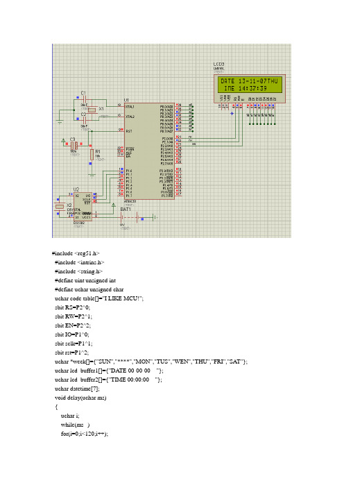
#include <intrins.h>
#include <string.h>
#define uint unsigned int
#define uchar unsigned char
uchar code table[]="I LIKE MCU!";
sbit RS=P2^0;
dispaly_string(0x00,lcd_buffer1);
dispaly_string(0x40,lcd_buffer2);
}
}
delay(5);
}
void write_a_byte_tods1302(uchar x)
{
uchar i;
for(i=0;i<8;i++)
{
IO=x&0x01;
sclk=1;
sclk=0;
x=x>>1;
}
}
uchar get_a_byte_fromds1302()
{
uchar i,b=0x00;
for(i=0;i<8;i++)
uchar lcd_buffer2[]={"TIME 00:00:00 "};
uchar datetime[7];
void delay(uchar ms)
{
uchar i;
while(ms--)
for(i=0;i<120;i++);
}
//忙检测
uchar busy()
{
uchar test;
RW=1;
{
单片机时钟芯片DS1302在LCD1602上显示年月日时分秒

单片机设计实验内容摘要:单片机实验是通过Proteus仿真并且与Keil相结合使用控制单片机使其在仿真中完成一系列所设计的程序。
我们这个小组所做的实验是仿真一个数字时钟,通过DS1302这个芯片从计算机上读取时间信息,再由51单片机对数据进行处理、分配,将其输出在LCD1602上,实现简单的数字时钟的功能。
设计内容及要求:(1)根据设计课题的技术指标和给定条件,在教师指导下,能够独立而正确地进行方案论证和设计计算,要求概念清楚、方案合理、方法正确、步骤完整;(2)要求学生掌握单片机的设计内容、方法和步骤;(3)要求会查阅有关参考资料和手册等;(4)要求学会选择有关元件和参数;(5)要求学会绘制有关电路图和设计流程图;(6)要求学会编写设计说明书。
系统框图:硬件选择:1、AT89C51AT89C51是一种带4K字节FLASH存储器(FPEROM—Flash Programmable and Erasable Read Only Memory)的低电压、高性能CMOS 8位微处理器,俗称单片机。
AT89C2051是一种带2K字节闪存可编程可擦除只读存储器的单片机。
单片机的可擦除只读存储器可以反复擦除1000次。
该器件采用ATMEL高密度非易失存储器制造技术制造,与工业标准的MCS-51指令集和输出管脚相兼容。
由于将多功能8位CPU和闪烁存储器组合在单个芯片中,ATMEL的AT89C51是一种高效微控制器,AT89C2051是它的一种精简版本。
AT89C51单片机为很多嵌入式控制系统提供了一种灵活性高且价廉的方案。
AT89C51外形及引脚排列主要特性:·与MCS-51 兼容·4K字节可编程FLASH存储器·寿命:1000写/擦循环·数据保留时间:10年·全静态工作:0Hz-24MHz·三级程序存储器锁定·128×8位内部RAM·32可编程I/O线·两个16位定时器/计数器·5个中断源·可编程串行通道·低功耗的闲置和掉电模式·片内振荡器和时钟电路特性概述:AT89C51 提供以下标准功能:4k 字节Flash 闪速存储器,128字节内部RAM,32 个I/O 口线,两个16位定时/计数器,一个5向量两级中断结构,一个全双工串行通信口,片内振荡器及时钟电路。
时钟DS1302在液晶1602显示程序
#include <reg52.h>#define uchar unsigned char#define uint unsigned intuchar code table[]="ziye334"; uchar code table1[]="0123456789"; uchar code table2[]="DAY-";sbit rs=P2^5;sbit rw=P2^6;sbit en=P2^7;sbit rst=P1^7;sbit io=P3^5;sbit clk=P1^6;sbit ACC0=ACC^0;sbit ACC7=ACC^7;sbit key1=P1^0;sbit key2=P1^1;sbit key3=P1^2;sbit key4=P1^3;sbit key5=P1^4;uchar num;uchar t_sec,sec1,sec2;uchar t_min,min1,min2;uchar t_hr,hr1,hr2;uchar t_mon,mon1,mon2; uchar t_date,date1,date2; uchar t_year,year1,year2; uchar t_day,day1,flag;void input_1byte(uchar TD) {uchar i;ACC=TD;for(i=8;i>0;i--){io=ACC0;clk=1;clk=0;ACC=ACC>>1;}}uchar output_1byte(void) {uchar i;for(i=8;i>0;i--){ACC=ACC>>1;ACC7=io;clk=1;clk=0;}return(ACC);}void write_ds1302(uchar add,uchar dat) {rst=0;clk=0;rst=1;input_1byte(add);input_1byte(dat);clk=1;rst=0;}uchar read_ds1302(uchar add){uchar inf;rst=0;clk=0;input_1byte(add);inf=output_1byte();clk=1;rst=0;return(inf);}void delay(uchar z) //延时{uint x,y;for(x=110;x>0;x--)for(y=z;z>0;z--);}void write_com(uchar com) //写指令{rs=0;rw=0;en=0;P0=com;delay(5);en=1;delay(5);}void write_date(uchar date) //写数据{rs=1;rw=0;en=0;P0=date;delay(5);en=1;delay(5);en=0;}void init_lcd(){en=0;write_com(0x38); //显示write_com(0x0c); //光标不显示write_com(0x06); //指针加1,整屏不移动write_com(0x01); //清屏write_com(0x80);}void init_1302(){write_ds1302(0x8e,0x00);//关闭写保护write_ds1302(0x90,0xaa); //定义充电write_ds1302(0x80,0x30); //秒write_ds1302(0x82,0x59);//分write_ds1302(0x84,0x23);//时write_ds1302(0x86,0x31);//日write_ds1302(0x88,0x12);//月write_ds1302(0x8a,0x04);//星期write_ds1302(0x8c,0x11);//年write_ds1302(0x8e,0x80);//打开写保护}void display(){t_sec=read_ds1302(0x81);sec1=t_sec&0x0f;sec2=(t_sec>>4);t_min=read_ds1302(0x83);min1=t_min&0x0f;min2=(t_min>>4);t_hr=read_ds1302(0x85); hr1=t_hr&0x0f;hr2=(t_hr>>4);t_date=read_ds1302(0x87); date1=t_date&0x0f;date2=(t_date>>4);t_mon=read_ds1302(0x89); mon1=t_mon&0x0f;mon2=(t_mon>>4);t_day=read_ds1302(0x8b); day1=t_day&0x0f;t_year=read_ds1302(0x8d); year1=t_year&0x0f;year2=(t_year>>4);write_com(0x80+0x4e);write_date(table1[sec2]); write_com(0x80+0x4f); write_date(table1[sec1]); write_com(0x80+0x4d); write_date(':');write_com(0x80+0x4c); write_date(table1[min1]); write_com(0x80+0x4b); write_date(table1[min2]); write_com(0x80+0x4a); write_date(':');write_com(0x80+0x49); write_date(table1[hr1]); write_com(0x80+0x48); write_date(table1[hr2]);write_com(0x80+0x0f); write_date(table1[date1]); write_com(0x80+0x0e); write_date(table1[date2]);write_com(0x80+0x0d);write_date('/');write_com(0x80+0x0c);write_date(table1[mon1]);write_com(0x80+0x0b);write_date(table1[mon2]);write_com(0x80+0x0a);write_date('/');write_com(0x80+0x09);write_date(table1[year1]);write_com(0x80+0x08);write_date(table1[year2]);write_com(0x80+0x40+5);write_date(table1[day1]); }void main(){init_lcd();delay(5);init_1302();delay(5);for(num=0;num<7;num++) {write_date(table[num]);delay(10);}write_com(0x80+0x41);for(num=0;num<4;num++) {write_date(table2[num]);delay(10);}while(1){if(flag==0){display();}}}。
基于DS1302和LCD1602的数字电子钟设计
关键词:单片机;DS1302;LCD1602;数字时钟
1
Abstract
This paper mainly introduces the hardware and software design of digital electronic clock which is made up of the AT89S52 MCU ,DS1302 clock chip and LCD1602 module .It can accurately adjust the information of the year,month,day,hour,minutes and seconds.This electronic clock has the characteristics of working accurately,keeping the time date when system losing power, and low power consumptions. Keywords: singlechip;DS1302;LCD1602;Digital clock
图(3)系统硬件连接原理图
8
三.系统软Leabharlann 设计[3]软件是单片机应用系统的灵魂,是整个系统的核心部分。如果把硬件比作人的手臂那么 软件就是人的大脑,手臂的一切动作的执行都要受控于大脑。同样,对 DS1302 时钟芯片和 1602 液晶显示模块的操作都是通过相应的软件程序来控制的。 3.1 DS1302 读写程序 任何一款数字芯片都有自己的操作时序,只有完全按照芯片厂商提供的操作时序进行编 程才可以使其正常工作。DS1302 的读写时序如图(4)所示。 按照此时序图编制的写操作程序如下:
2
一.引言
1.DS1302 时钟芯片简介[1]
基于51单片机与DS1302时钟芯片和LCD1602液晶显示的数字时钟

unsigned char DS1302OutputByte(void) {
unsigned char i; for(i=8; i>0; i--) {
ACC = ACC >>1; ACC7 = DS1302_IO; DS1302_CLK = 1; DS1302_CLK = 0; } return(ACC); }
P3.0/RXD P3.1/TXD P3.2/INT0 P3.3/INT1
P3.4/T0 P3.5/T1 P3.6/WR P3.7/RD
D1 LC
SD E
S V
VD
E V
S R
RW E
0 1 2 3 4 5 67 D D D D D D DD
D N +5V G 39 38
37
36 35
34
33 32
GotoXY(0,0); Print(" tian ma dian zi"); GotoXY(0,1); Print("Time: ");
Word 文档
.
while(1) {
DS1302_GetTime(&CurrentTime); TimeToStr(&CurrentTime); GotoXY(6,1); Print(CurrentTime.TimeString);
unsigned char i; ACC = d; for(i=8; i>0; i--) {
DS1302_IO = ACC0; DS1302_CLK = 1;
// 实时时钟写入一字节 (部函数 ) // 相当于汇编中的 RRC
Word 文档
.
DS1302_CLK = 0; ACC = ACC >> 1; } }
基于DS1302和LCD1602的可调数字钟

学习情境2-可调式数字钟之基于DS1302和LCD1602的可调数字钟☆点名,复习1、DS1302的引脚及其功能,以及DS1302和单片机的硬件连接?2、如何对DS1302读写数据,如何得到DS1302的时钟?☆新课讲授2.3 基于DS1302和LCD1602设计的可调数字钟上堂课程我们学会了使用DS1302,知道了如何在单片机系统中的连接,也详细的学习了如何得到DS1302的时钟,并且我们使用了16个数码管把年月日和时分秒实时地显示出来。
但数码管的显示毕竟有其自身的缺陷,现在在工业控制的各个环节,都使用液晶进行人机联系。
在日常生活中,我们对液晶显示器并不陌生。
液晶显示模块已作为很多电子产品的通用器件,如在计算器、万用表、电子表及很多家用电子产品中都可以看到,显示的主要是数字、专用符号和图形。
在单片机的人机交流界面中,一般的输出方式有以下几种:发光管、LED 数码管、液晶显示器。
发光管和LED数码管比较常用,软硬件都比较简单,在单片机系统中使用液晶显示器作为输出器件有以下几个优点:(1)显示质量高,由于液晶显示器每一个点在收到信号后就一直保持那种色彩和亮度,恒定发光,而不像阴极射线管显示器(CRT)那样需要不断刷新新亮点。
因此,液晶显示器画质高且不会闪烁。
(2)数字式接口,液晶显示器都是数字式的,和单片机系统的接口更加简单可靠,操作更加方便。
(3)体积小、重量轻,液晶显示器通过显示屏上的电极控制液晶分子状态来达到显示的目的,在重量上比相同显示面积的传统显示器要轻得多。
(4)功耗低,相对而言,液晶显示器的功耗主要消耗在其内部的电极和驱动IC上,因而耗电量比其它显示器要少得多。
2.3.1 LCD1602技术资料2.3.1.1 液晶显示简介1、液晶显示原理:液晶显示的原理是利用液晶的物理特性,通过电压对其显示区域进行控制,有电就有显示,这样即可以显示出图形。
液晶显示器具有厚度薄、适用于大规模集成电路直接驱动、易于实现全彩色显示的特点,目前已经被广泛使用在便携式电脑、数字摄像机、PDA移动通信工具等众多领域。
基于ds1302的51单片机简易实时时钟-1602显示-源程序
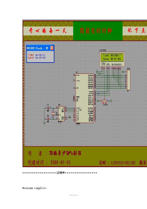
==================主程序================= #include <reg51.h>。
#include "ds1302.h"#include "LCD1602.h"void change();uchar times[9];uchar date[9];main(){LCD_init();//LCD初始化init_1302(time_1302);gotoxy(1,1);LCD_display("Time:");gotoxy(1,2);LCD_display("Date:");times[8]='\0';//date[8]='\0';while(1){get_1302(time_1302);change();gotoxy(7,1);LCD_display(times);gotoxy(7,2);LCD_display(date);}}/*=========================== 转换子程序===========================*/void change(){// 时间的转换times[0]=time_1302[2]/10+'0';times[1]=time_1302[2]%10+'0';times[2]=':';times[3]=time_1302[1]/10+'0';times[4]=time_1302[1]%10+'0';times[5]=':';times[6]=time_1302[0]/10+'0';times[7]=time_1302[0]%10+'0';// 日期的转换date[0]=time_1302[6]/10+'0';date[1]=time_1302[6]%10+'0';date[2]='-';date[3]=time_1302[4]/10+'0';date[4]=time_1302[4]%10+'0';date[5]='-';date[6]=time_1302[3]/10+'0';date[7]=time_1302[3]%10+'0';}======================================================DS1302驱动程序=============#define uchar unsigned charuchar time_1302[7]={0x00,0x00,0x00,0x03,0x07,0x03,0x08};//设置时间初始值数组// 秒分时号月份星期年sbit T_IO=P1^0; //与硬件相关的连线clk为DS1302的时钟信号线sbit T_CLK=P1^1; //DAT为DS1302的I/O数据线sbit T_RST=P1^2; //RST为DS1302的RST信号线uchar bdata datbyte;sbit datbyte0=datbyte^0;sbit datbyte7=datbyte^7;void get_1302(uchar time[]);void write_ds1302(uchar dat);uchar r_1302(uchar add);void w_1302(uchar add,uchar dat);uchar read_ds1302(void);void init_1302(uchar *time);/*==========================================D S 1 3 0 2 初始化===========================================*/void init_1302(uchar *time){uchar i, add;//uchar time_bcd[7];add=0x80;//0写入,1读出w_1302(0x8e,0x00);for(i=0;i<7;i++){w_1302(add,*time);add+=2;time++;}w_1302(0x8e,0x80);}//===========================// 读取当前时间//===========================void get_1302(uchar time[]){uchar i;uchar add=0x81;w_1302(0x8e,0x00);for(i=0;i<7;i++){time[i]=r_1302(add);add+=2;}w_1302(0x8e,0x80);}/*================================= DS1302写入一个字节(上升沿有效)=================================*/void write_ds1302(uchar dat){uchar i;datbyte=dat;for(i=0;i<8;i++){T_IO=datbyte0;T_CLK=1;T_CLK=0;datbyte=datbyte>>1;}}/*======================================= DS1302读取一个字节(下降沿有效)=======================================*/uchar read_ds1302(void){uchar i;for(i=0;i<8;i++){datbyte=datbyte>>1;datbyte7=T_IO;T_CLK=1;T_CLK=0;}return(datbyte);}/*========================================= 指定位置读取数据=========================================*/uchar r_1302(uchar add){uchar temp,dat1,dat2;T_RST=0;T_CLK=0;T_RST=1;write_ds1302(add);temp=read_ds1302();T_CLK=1;T_RST=0;dat1=temp/16;dat2=temp%16;temp=dat1*10+dat2;return(temp);}/*========================================== 指定位置写入数据==========================================*/void w_1302(uchar add,uchar dat){T_RST=0;T_CLK=0;T_RST=1;write_ds1302(add);write_ds1302(dat/10<<4|dat%10);T_CLK=1;T_RST=0;}=========================================== =============LCD1602驱动程序================#define LCD_DB P0//定义LCD的数据端口sbit LCD_RS=P2^0;sbit LCD_RW=P2^1;sbit LCD_E=P2^2;#define uchar unsigned char#define uint unsigned int//===========延时子函数======================== void delay_lcd(uint x){uint i,j;for(i=x;i>0;i--)for(j=0;j<2;j++);}//==================写指令函数================= void LCD_write_command(uchar command){LCD_DB=command;LCD_RS=0;//指令LCD_RW=0;//写入LCD_E=1;LCD_E=0;delay_lcd(1);//等待执行完毕。
DS1302+LCD1602时钟
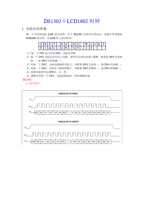
DS1302+LCD1602时钟1.实验目的效果:做一个不怕掉电的LCD显示时钟。
学习DS1302时钟芯片的读写,加强字符型液晶LCD1602的应用。
在LCD屏上显示格式:1)按一下SW1进入时间调整,关标会闪烁2)按一下SW2光标会在年份上闪烁,表明可以对年份进行调整,接着按SW3年份将加一,按SW4年份将减一;2)再按一下SW2,光标闪烁移到月份上,同样按SW3月份加一,按SW4月份减一;3)再按一下SW2,光标有下移到星期上,同样按SW3星期加一,按SW4星期减一;4)同样的道理可以调整时,分,秒。
5)调整完毕按一下SW1,光标闪烁退出,时间调整结束。
DS1302:1)读写时序:2)DS1302相关寄存器:(详细DS1302资料请查看ds1302.pdf文档)2.原理图:DS1302连接原理图LCD1602连接原理图3.实验板上操作:1)用三个短路冒将SCLK-P3.5,I/O-P3.6,CE-P3.7短接起来。
2)将板上的相应拨码开关拨到拨到ON上。
(建议把原来做过数码管显示的那个拨码开关全部拨到OFF那边)3)把LCD1602液晶插到实验板上的LCD1602液晶插槽上。
(提示:程序烧进单片机后,液晶上没有显示,请调节板子上左上角那个电位器)4)按一下SW1进入时间调整,关标会闪烁按一下SW2光标会在年份上闪烁,表明可以对年份进行调整,接着按SW3年份将加一,按SW4年份将减一;再按一下SW2,光标闪烁移到月份上,同样按SW3月份加一,按SW4月份减一;再按一下SW2,光标有下移到星期上,同样按SW3星期加一,按SW4星期减一;同样的道理可以调整时,分,秒。
调整完毕按一下SW1,光标闪烁退出,时间调整结束。
4.实物连接图如下:5.C语言程序:#include "A T89X51.h"#include "intrins.h"#define HIGH 1#define LOW 0#define TRUE 1#define ZERO 0#define MSB 0x80#define LSB 0x01// ds1302 PreDefinition#define DS1302_WP0x8E#define DS1302_RESET RST=LOW;SCL=LOW;RST=HIGH#define DS1302_WP_ENABLE Write_Ds1302(DS1302_WP,0X00)#define DS1302_WP_DISENABLE Write_Ds1302(DS1302_WP,0x00) #define LCDPORT P0sbit SCL = P3^5;// DS1302 Serial-Clock Input pin 5sbit SDA = P3^6;// DS1302 Serial-Data Input pin 6sbit RST = P3^7;// DS1302 Chip-Seclet Input pin 7sbit RS=P1^0;sbit RW=P1^1;sbit EN=P1^2;code unsigned char set_rtc_code[7]={0x07,0x03,0x29,0x02,0x21,0x07,0x40};code unsigned char write_rtc_address[7]={0x8c,0x88,0x86,0x8a,0x84,0x82,0x80};code unsigned char read_rtc_address[7]={0x8d,0x89,0x87,0x8b,0x85,0x83,0x81}; unsigned char read_rtc_code[7]; //DS1302读出信息(年份,星期,时间)暂存数组,/********1ms延时子程序***********/delay_nms(unsigned int n){unsigned int i;unsigned char j;for(i=0;i<n;i++)for(j=0;j<120;j++); //空操作}//*************LCD1602驱动程序***************************//void lcd_delay(unsigned char delaytime){while(delaytime)delaytime--;}void write_lcd_command(unsigned char write_command){lcd_delay(40);RS=0;RW=0;LCDPORT=write_command;EN=1;EN=0;}void write_lcd_data(unsigned char write_data){lcd_delay(40);RS=1;RW=0;LCDPORT=write_data;EN=1;EN=0;}void LCD_write_char( unsigned x,unsigned char y,unsigned char dat) //x表示行,y表示该行的位置(也就是列){//LCD_set_xy( x, y );switch(x){case 0:write_lcd_command(0x80+y);break;case 1:write_lcd_command(0xc0+y);break;}// LCD_en_dat(dat);write_lcd_data(dat|0x30); //dat或上0x30,就时把数字0123456789转换成ASIIC码}void lcd_displaystr(unsigned char x,unsigned char y,unsigned char code *str){switch(x){case 0:write_lcd_command(0x80+y);break;case 1:write_lcd_command(0xc0+y);break;}while (*str){write_lcd_data(*str);str++;}}void initial_lcd1602(void) //初始化LCD1602{unsigned char i;EN=0;for(i=200;i>0;i--)lcd_delay(248);write_lcd_command(0x38);for(i=4;i>0;i--)lcd_delay(248);write_lcd_command(0x38);for(i=4;i>0;i--)lcd_delay(248);write_lcd_command(0x0f);for(i=4;i>0;i--)lcd_delay(248);write_lcd_command(0x06);for(i=4;i>0;i--)lcd_delay(248);write_lcd_command(0x01);for(i=4;i>0;i--)lcd_delay(248);}//********************lcd1602驱动程序到此完********************/////////////////////////////////////////////////////////////////////////**************ds1302读写程序*************************//void Write_Ds1302_Byte(unsigned char temp) //写一个字节{unsigned char i;for (i=0;i<8;i++){SCL=LOW;SDA=temp&LSB;temp>>=1;SCL=HIGH;}}/****************************************************************************/ void Write_Ds1302( unsigned char address,unsigned char dat ) //写ds1302{DS1302_RESET;Write_Ds1302_Byte(address);Write_Ds1302_Byte(dat);RST=LOW;}/****************************************************************************/ unsigned char Read_Ds1302 ( unsigned char address ) //读ds1302{unsigned char i,temp=0x00,temp_temp;DS1302_RESET;Write_Ds1302_Byte(address);for (i=0;i<8;i++){if(SDA)temp|=0x80;SCL=LOW;temp>>=1;SCL=HIGH;}RST=LOW;temp_temp=temp/16;temp=temp%16;temp=temp+temp_temp*10;return (temp);}/****************************************************************************/ void Read_RTC(void) //读出DS1302里的相关信息,存放在read_rtd_code[]数组中{unsigned char i,*p;p=read_rtc_address;for(i=0;i<7;i++){read_rtc_code[i]=Read_Ds1302(*p);p++;}}/***********************************************************************/void Set_RTC(void) //初始化设置DS1302{unsigned char i,*p;p=write_rtc_address;for(i=0;i<7;i++){Write_Ds1302(*p,set_rtc_code[i]);p++;}}/******************************************************/void initial_ds1302(void) //初始化ds1302{DS1302_WP_ENABLE;Set_RTC();}/**************ds1302读写程序到此完************************//////////////////////////////////////////////////////系统初始化void system_initial(void){initial_ds1302();initial_lcd1602();}/****************************************************************************/void main(void){unsigned char count,staus;system_initial();//输出显示lcd_displaystr(0,0x00,"20");delay_nms(10);lcd_displaystr(0,0x04,"-");delay_nms(10);lcd_displaystr(0,0x07,"-");lcd_displaystr(0,0x0b,"Week:");lcd_displaystr(1,0x00,"Time:");lcd_displaystr(1,0x07,":");lcd_displaystr(1,0x0a,":");while(1){//按键扫描,实现对时间的调整,对应实验板的独立按钮//开始时间设置,staus=1if(P2_0==0){delay_nms(10);if(P2_0==0){staus^=1;count=0;while(P2_0==0);}}if(P2_1==0){delay_nms(10);if(P2_1==0){count++; //光标移位if(count==8)count=1;while(P2_1==0);}}if(P2_2==0) //加按钮{delay_nms(10);if(P2_2==0){switch(count){case 0x01:read_rtc_code[0]++;DS1302_WP_ENABLE;Write_Ds1302(write_rtc_address[0],(read_rtc_code[0]+(read_rtc_code[0]/10)*6));LCD_write_char(0,0x02,(read_rtc_code[0]/10)); //年十位LCD_write_char(0,0x03,(read_rtc_code[0]%10)); //年个位break;case 0x02:read_rtc_code[1]++;if(read_rtc_code[1]==13)read_rtc_code[1]=1;DS1302_WP_ENABLE;Write_Ds1302(write_rtc_address[1],(read_rtc_code[1]+(read_rtc_code[1]/10)*6));LCD_write_char(0,0x05,(read_rtc_code[1]/10)); //月十位LCD_write_char(0,0x06,(read_rtc_code[1]%10)); //月个位break;case 0x03:read_rtc_code[2]++;if(read_rtc_code[2]==31)read_rtc_code[2]=1;DS1302_WP_ENABLE;Write_Ds1302(write_rtc_address[2],(read_rtc_code[2]+(read_rtc_code[2]/10)*6));LCD_write_char(0,0x08,(read_rtc_code[2]/10)); //日十位LCD_write_char(0,0x09,(read_rtc_code[2]%10)); //日个位break;case 0x04:read_rtc_code[3]++;if(read_rtc_code[3]==8)read_rtc_code[3]=1;DS1302_WP_ENABLE;Write_Ds1302(write_rtc_address[3],(read_rtc_code[3]+(read_rtc_code[3]/10)*6));LCD_write_char(0,0x0f,(read_rtc_code[3]%10)); //星期break;case 0x05:read_rtc_code[4]++;if(read_rtc_code[4]==25)read_rtc_code[4]=0;DS1302_WP_ENABLE;Write_Ds1302(write_rtc_address[4],(read_rtc_code[4]+(read_rtc_code[4]/10)*6));LCD_write_char(1,0x05,(read_rtc_code[4]/10)); //时十位LCD_write_char(1,0x06,(read_rtc_code[4]%10)); //时个位break;case 0x06:read_rtc_code[5]++;if(read_rtc_code[5]==60)read_rtc_code[5]=0;DS1302_WP_ENABLE;Write_Ds1302(write_rtc_address[5],(read_rtc_code[5]+(read_rtc_code[5]/10)*6));LCD_write_char(1,0x08,(read_rtc_code[5]/10)); //分十位LCD_write_char(1,0x09,(read_rtc_code[5]%10)); //分个位break;case 0x07:read_rtc_code[6]++;if(read_rtc_code[6]==60)read_rtc_code[6]=0;DS1302_WP_ENABLE;Write_Ds1302(write_rtc_address[6],(read_rtc_code[6]+(read_rtc_code[6]/10)*6));LCD_write_char(1,0x0b,(read_rtc_code[6]/10)); //秒十位LCD_write_char(1,0x0c,(read_rtc_code[6]%10)); //秒个位break;default:break;}while(P2_2==0);}}if(P2_3==0) //减按钮{delay_nms(10);if(P2_3==0){switch(count){case 0x01:if(read_rtc_code[0]==0){lcd_displaystr(0,0x00,"19");read_rtc_code[0]=99;}elseread_rtc_code[0]--;DS1302_WP_ENABLE;Write_Ds1302(write_rtc_address[0],(read_rtc_code[0]+(read_rtc_code[0]/10)*6));LCD_write_char(0,0x02,(read_rtc_code[0]/10)); //年十位LCD_write_char(0,0x03,(read_rtc_code[0]%10)); //年个位break;case 0x02:if(read_rtc_code[1]==1)read_rtc_code[1]=12;elseread_rtc_code[1]--;DS1302_WP_ENABLE;Write_Ds1302(write_rtc_address[1],(read_rtc_code[1]+(read_rtc_code[1]/10)*6));LCD_write_char(0,0x05,(read_rtc_code[1]/10)); //月十位LCD_write_char(0,0x06,(read_rtc_code[1]%10)); //月个位break;case 0x03:if(read_rtc_code[2]==1)read_rtc_code[2]=30;elseread_rtc_code[2]--;DS1302_WP_ENABLE;Write_Ds1302(write_rtc_address[2],(read_rtc_code[2]+(read_rtc_code[2]/10)*6));LCD_write_char(0,0x08,(read_rtc_code[2]/10)); //日十位LCD_write_char(0,0x09,(read_rtc_code[2]%10)); //日个位break;case 0x04:if(read_rtc_code[3]==1)read_rtc_code[3]=7;elseread_rtc_code[3]--;DS1302_WP_ENABLE;Write_Ds1302(write_rtc_address[3],(read_rtc_code[3]+(read_rtc_code[3]/10)*6));LCD_write_char(0,0x0f,(read_rtc_code[3]%10)); //星期break;case 0x05:if(read_rtc_code[4]==0)read_rtc_code[4]=24;elseread_rtc_code[4]--;DS1302_WP_ENABLE;Write_Ds1302(write_rtc_address[4],(read_rtc_code[4]+(read_rtc_code[4]/10)*6));LCD_write_char(1,0x05,(read_rtc_code[4]/10)); //时十位LCD_write_char(1,0x06,(read_rtc_code[4]%10)); //时个位break;case 0x06:if(read_rtc_code[5]==00)read_rtc_code[5]=59;elseread_rtc_code[5]--;DS1302_WP_ENABLE;Write_Ds1302(write_rtc_address[5],(read_rtc_code[5]+(read_rtc_code[5]/10)*6));LCD_write_char(1,0x08,(read_rtc_code[5]/10)); //分十位LCD_write_char(1,0x09,(read_rtc_code[5]%10)); //分个位break;case 0x07:if(read_rtc_code[6]==0)read_rtc_code[6]=59;elseread_rtc_code[6]--;DS1302_WP_ENABLE;Write_Ds1302(write_rtc_address[6],(read_rtc_code[6]+(read_rtc_code[6]/10)*6));LCD_write_char(1,0x0b,(read_rtc_code[6]/10)); //秒十位LCD_write_char(1,0x0c,(read_rtc_code[6]%10)); //秒个位break;default:break;}while(P2_3==0);}}if(staus==0){//读出DS1302寄存器里的时间信息RST=HIGH;Read_RTC();LCD_write_char(0,0x02,(read_rtc_code[0]/10)); //年十位LCD_write_char(0,0x03,(read_rtc_code[0]%10)); //年个位LCD_write_char(0,0x05,(read_rtc_code[1]/10)); //月十位LCD_write_char(0,0x06,(read_rtc_code[1]%10)); //月个位LCD_write_char(0,0x08,(read_rtc_code[2]/10)); //日十位LCD_write_char(0,0x09,(read_rtc_code[2]%10)); //日个位LCD_write_char(0,0x0f,(read_rtc_code[3]%10)); //星期LCD_write_char(1,0x05,(read_rtc_code[4]/10)); //时十位LCD_write_char(1,0x06,(read_rtc_code[4]%10)); //时个位LCD_write_char(1,0x08,(read_rtc_code[5]/10)); //分十位LCD_write_char(1,0x09,(read_rtc_code[5]%10)); //分个位LCD_write_char(1,0x0b,(read_rtc_code[6]/10)); //秒十位LCD_write_char(1,0x0c,(read_rtc_code[6]%10)); //秒个位}else{RST=LOW;switch(count){case 0x01:write_lcd_command(0x83);break;case 0x02:write_lcd_command(0x86);break;case 0x03:write_lcd_command(0x89);break;case 0x04:write_lcd_command(0x8f);break;case 0x05:write_lcd_command(0xc6);break;case 0x06:write_lcd_command(0xc9);break;case 0x07:write_lcd_command(0xcc);break;default:break;}}}}。
基于51单片机数字时钟 毕业设计(论文)
本科毕业设计(论文)题目:基于51单片机的数字时钟系统软件设计基于51单片机的数字时钟系统软件设计摘要本文介绍了一款多功能数字时钟系统的软件设计。
该系统能够显示当前日期、时间,并且具有日期、时间设置以及闹钟等功能。
该系统采用51系列STC 公司生产的STC89C51单片机,以及DALLAS公司生产的数字时钟芯片DS1302,利用液晶显示器LCD1602显示数字时钟的结果。
本系统的软件设计使用C语言进行编程,利用目前流行的Keil软件编程环境对源程序进行编译。
系统的软件程序主要包括主程序、DS1302初始化程序、读DS1302程序、写DS1302程序、LCD1602显示程序、日期时间调整、定时报警等子程序的设计。
该系统具有友好的用户界面、操作简单、性能稳定。
该数字时钟系统能够长期、连续、可靠、稳定地工作,同时系统还具有体积小、功耗低等特点,便于携带、使用方便。
关键词:DS1302数字时钟芯片;STC89C51单片机;LCD1602液晶显示器;软件设计Software Design of Digital Clock System Based on 51 MCUAbstractThis article describes the multi-functional digital clock system software design. The system can display the current date, time, and has the date and time settings and the alarm clock functions.What is introduced in this article is about the software design of a digital clock system which is multifunctional. This system can display the present time and date, it also has function such as setting time and date or being used as an alarm clock. The system uses a STC89C51 microcontroller of the 51 series produced by the STC corporation and a DS1302 digital clock chip produced by the DALLAS corporation. It shows people how the digital clock goes with a liquid crystal display LCD1602.The software design of this system is programmed with the C programming language and the program is compiled with the Keil software programming environment which is quite popular now. The software programs of the system mainly include the designs of some subroutines such as the DS1302 initialization program、the DS1302 program of reading、the DS1302 program of writing、the LCD1602 display program、adjustment of the date and time, timing alarm and so on.The system is provided with a friendly user interface、simple operation and stable function. The digital clock system can work long、continuously、reliably and stable while it also has characteristics like small volume and low power consumption which allow people to use conveniently and take it with themselves easily.Key words:DS1302 digital clock chip;STC89C51 Microcontroller; LCD1602 liquid crystal displayer; software design.目录1 绪论 (1)1.1 课题研究的背景 (1)1.2 课题研究的意义 (2)1.3 数字时钟的应用及发展前景 (2)1.4 课题的研究内容及技术要求 (3)2 设计要求与方案论证 (4)2.1 设计基本要求 (4)2.2 编程语言方案论证 (4)2.2.1 汇编语言 (4)2.2.2 C语言 (5)2.3 显示方式方案论证 (5)2.3.1 利用LED数码管显示结果 (5)2.3.2 利用LCD液晶显示结果 (6)2.4 系统仿真方式方案论证 (6)2.4.1 利用Protues软件仿真实现 (6)2.4.2 手工焊接电路板 (7)3 系统主要器件的工作原理 (8)3.1 单片机STC89C51的工作原理 (8)3.1.1 单片机主要性能参数及引脚功能 (8)3.1.2 单片机存储器结构及复位电路与时钟电路 (11)3.2 时钟芯片DS1302的原理及应用 (12)3.2.1 时钟芯片DS1302的结构原理及控制字节 (12)3.2.2 DS1302数据输入输出(I/O)与寄存器 (14)3.3 LCD1602的结构及工作原理 (15)4 系统软件设计 (17)4.1 系统硬件组成及结构框图 (17)4.2 系统软件设计概述 (17)4.3 系统主程序设计 (18)4.4 时钟芯片DS1302子程序设计 (19)4.4.1 DS1302初始化程序设计 (19)4.4.2 CPU读DS1302程序设计 (19)4.4.3 CPU写DS1302程序设计 (21)4.5 时间调整子程序设计 (22)4.6 定时报警子程序设计 (24)5 系统调试 (25)5.1 系统硬件调试 (25)5.2 软件调试 (26)5.2.1 软件编程环境keil介绍 (26)5.2.2 软件调试 (29)5.2.3 利用下载编程软件STC-ISP下载程序 (29)5.3 系统调试结果 (32)6 结论 (33)参考文献 (35)致谢............................................................................................................错误!未定义书签。
DS1302时钟LCD1602显示
/**************************************************************** ** DS1302时钟******************************************************************/ #include<reg51.h>#include<intrins.h>#define uchar unsigned char#define uint unsigned int//--定义矩阵键盘使用的IO口--//#define GPIO_DIG P0#define GPIO_KEY P1//---定义lcd1602使用的IO口---//#define DB P0//--定义全局变量--//uchar error[]="Error!!!" ;//存放字符串“Error!!!”char KeyValue=-1;//用来存放读取到的键值uchar flag=0;//用来检测是否更改过时间uchar tt0=0;//中断里面的参数uchar beeflag=0;//看看有没有开闹钟//---定义蜂鸣器使用的IO口---//sbit bee=P2^3;//定义LCD1602使用的IO口//sbit LCDE=P2^7;sbit RS=P2^6;sbit RW=P2^5;//---定义ds1302使用的IO口---//sbit DSIO=P3^4; //数据传输口sbit RST=P3^5; //进行传输时,RST必须置高sbit SCLK=P3^6; //上沿读数据,下沿写数据//---DS1302写入和读取时分秒的地址命令---////---秒分时日月周年最低位读写位;-------//uchar code READ_RTC_ADDR[7] = {0x81, 0x83, 0x85, 0x87, 0x89, 0x8b, 0x8d}; uchar code WRITE_RTC_ADDR[7] = {0x80, 0x82, 0x84, 0x86, 0x88, 0x8a, 0x8c};//---键盘写入地址-------//uchar kyewrite[] = {0x82, 0x83, 0x85, 0x86, 0x88, 0x89, 0x8d,0xc0,0xc1,0xc3,0xc4,0xc6,0xc7};//用于判断增减//char addorm[]={0x01,0x10,-0x01,-0x10};//---DS1302时钟初始化2013年1月1日星期二12点00分00秒。
基于单片机的LCD1602电子时钟设计

基于单片机的LCD1602电子时钟设计近年来,随着物联网和智能设备的快速发展,电子时钟作为一种常见的智能设备,广泛应用于家庭、办公室等各种场合。
本文将基于单片机设计一款LCD1602电子时钟,实现时间显示、闹钟设置等功能。
一、硬件设计1.单片机选择在本设计中,选择常用的51系列单片机AT89C51,具有丰富的外设资源和强大的处理能力。
该单片机具有8位数据总线、16位地址总线,并且集成了定时/计数器、中断控制器和串行通信接口等外设。
2.显示模块选择3.时钟模块选择通过接入DS1302时钟模块,可以实现实时时钟的功能。
DS1302模块具有时钟计数器、电压检测电路、串行通信接口等,并且具有低功耗特点。
4.控制板设计根据LCD1602的引脚连接方式,设计一个控制板,用于将单片机、显示模块和时钟模块等连接在一起。
同时,需注意设计供电电路、外设输入输出电平等电路。
二、软件设计1.初始化设置通过单片机的GPIO口配置,将LCD1602和DS1302对应的引脚设置为输出模式,同时初始化LCD显示屏并进行清屏操作。
此外,需设置DS1302时钟模块的时钟、日期、闹钟等参数。
2.时间显示通过读取DS1302时钟模块的计数器,获得当前的小时、分钟和秒数,然后将其格式化为HH:MM:SS的形式,并通过LCD显示出来。
3.时间设置通过单片机的外部中断,当用户按下设置按钮后,进入时间设置模式。
在时间设置模式下,用户可以通过按下不同的按键来调整小时、分钟和秒数。
调整完成后,再次按下设置按钮即可保存设置。
4.闹钟设置通过单片机的定时器中断,设定一个闹钟定时器。
当闹钟定时器触发时,触发相应的中断,然后通过LCD显示闹钟提示。
此外,用户也可以通过按下按钮来设置闹钟时间,并通过单片机的外部中断进行处理。
5.闹钟响铃当闹钟时间到达时,触发相应的中断,通过LCD显示闹钟提示,并通过蜂鸣器发出响铃声。
总结通过本设计,可以实现一款功能齐全的LCD1602电子时钟。
基于51单片机的用 LCD1602 显示时钟的程序
用LCD1602 显示的时钟2012-04-30 15:04有这样一个题目:求一个为51 单片机编写的LCD 电子时钟的设计,简单就好!希望说一下怎么设计这个时钟,都需要些什么东西,最重要的——把这个设计需要的程序写出来。
设计的任务:以单片机控制的时钟,在LCD 显示器上显示当前的时间。
设计的基本要求:1.使用文字型LCD 显示器显示当前时间。
2.显示格式为“时时:分分:秒秒”。
3.用4个功能键操作来设置当前时间。
各个功能键的功能如下:K1:进入设置现在的时间。
K2:设置小时。
K3:设置分钟。
K4:确认完成设置。
4. 程序执行后工作指示灯LED 闪烁,表示程序开始执行,LCD 显示“00:00:00”,然后开始计时。
题目链接:/question/416705477.html//==================================================提到设计时钟,很多人都想到了时钟芯片DS1302,都说它简单、准确。
其实,这是个误区。
仅仅使用一般的单片机,简单的编程,达到相同DS1302 的准确度,并不是难事。
如果不要求计算平闰年、不要求分清大小月、不要求计算星期几,只是要求一个简单的时钟(及日历),用DS1302,就是自寻烦恼。
大家可以打开题目链接,看看其中的一些答案,就可以看出使用DS1302 是多么的繁琐了,简直就是一场噩梦。
做而论道以前就使用普通的单片机和LCD1602 设计过《时钟与日历》,程序设计的非常合理,时间精度就完全取决于晶振的精度。
设计出来的时钟,几个月都差不上一秒。
针对这个题目,做而论道翻出了以前的设计,删节了一些不需要的功能,设计出了符合题目要求的时钟,用PROTEUS 仿真截图如下:程序用C 语言编写,全部代码如下://---------------------------------------------------#include<reg52.h>#define uchar unsigned char#define uint unsigned int#define KEY_IO P3#define LCD_IO P0sbit LCD_RS = P2^0;sbit LCD_RW = P2^1;sbit LCD_EN = P2^2;sbit SPK = P1^2;sbit LED = P2^4;bit new_s, modify = 0;char t0, sec = 50, min = 59, hour = 23;char code LCD_line1[] = "Designed by ZELD"; char code LCD_line2[] = "Timer: 00:00:00 "; char Timer_buf[] = "23:59:50";//---------------------------------------------------void delay(uint z){uint x, y;for(x = z; x > 0; x--) for(y = 100; y > 0; y--);//---------------------------------------------------void W_LCD_Com(uchar com) //写指令{LCD_RS = 0; LCD_IO = com; // LCD_RS和R/W都为低电平时,写入指令LCD_EN = 1; delay(5); LCD_EN = 0; //用EN输入一个高脉冲}//---------------------------------------------------void W_LCD_Dat(uchar dat) //写数据{LCD_RS = 1; LCD_IO = dat; // LCD_RS为高、R/W为低时,写入数据LCD_EN = 1; delay(5); LCD_EN = 0; //用EN输入一个高脉冲}//---------------------------------------------------void W_LCD_STR(uchar *s) //写字符串{while(*s) W_LCD_Dat(*s++);}//---------------------------------------------------void W_BUFF(void) //填写显示缓冲区{Timer_buf[7] = sec % 10 + 48; Timer_buf[6] = sec / 10 + 48;Timer_buf[4] = min % 10 + 48; Timer_buf[3] = min / 10 + 48;Timer_buf[1] = hour % 10 + 48;Timer_buf[0] = hour / 10 + 48;W_LCD_Com(0xc0 + 7); W_LCD_STR(Timer_buf);}//---------------------------------------------------uchar read_key(void){uchar x1, x2;KEY_IO = 255;x1 = KEY_IO;if (x1 != 255) {delay(100);x2 = KEY_IO;if (x1 != x2) return 255;while(x2 != 255) x2 = KEY_IO;if (x1 == 0x7f) return 0;else if (x1 == 0xbf) return 1;else if (x1 == 0xdf) return 2;else if (x1 == 0xef) return 3;else if (x1 == 0xf7) return 4;}return 255;//---------------------------------------------------void Init(){LCD_RW = 0;W_LCD_Com(0x38); delay(50);W_LCD_Com(0x0c);W_LCD_Com(0x06);W_LCD_Com(0x01);W_LCD_Com(0x80); W_LCD_STR(LCD_line1);W_LCD_Com(0xC0); W_LCD_STR(LCD_line2);TMOD = 0x01; //T0定时方式1TH0 = 0x4c;TR0 = 1; //启动T0PT0 = 1; //高优先级, 以保证定时精度ET0 = 1;EA = 1;}//---------------------------------------------------void main(){uint i, j;uchar Key;Init();while(1) {//-------------------------------if (new_s) { //如果出现了新的一秒, 修改时间new_s = 0; sec++; sec %= 60;if(!sec) { min++; min %= 60;if(!min) { hour++; hour %= 24;}}W_BUFF(); //写显示//-------------------------------if (!sec && !min) { //整点报时for (i = 0; i < 200; i++) {SPK = 0; for (j = 0; j < 100; j++);SPK = 1; for (j = 0; j < 100; j++);} }}//-------------------------------Key = read_key(); //读出按键switch(Key) { //分别处理四个按键case 0: modify = 1; break;case 1: if(modify) {min++; min %= 60; W_BUFF(); break;}case 2: if(modify) {hour++; hour %= 24; W_BUFF(); break;}case 3: modify = 0; break;} }}//---------------------------------------------------void timer0(void) interrupt 1 //T0中断函数, 50ms执行一次{TH0 = 0x4c;t0++; t0 %= 20; //20, 一秒钟if(t0 == 0) {new_s = 1; LED = ~LED;}if(modify) LED = 0;}//===================================================呵呵,全部程序,也不过120 行左右。
如何实现DS1302实时时钟表显示在1602LCD液晶
如何实现DS1302实时时钟表显示在1602LCD液晶在1602LCD 液晶里显示实时时间:首先在DS1302 实时时钟芯片里写入一个时间,然后在这个芯片里读取这个时间,并显示在液晶里。
现在终于实现了...#include#include sbit SCLK=P3;sb it SDA=P3;sb it RST = P3 ;//unsigned char code Write_Address[]={0x80,0x82,0x84}; unsigned char code Read_Address[]={0x85,0x83,0x81}; unsigned char Time_Table[3];void Write_Byte(unsigned char Data)//写一个字节: 地址或数据{ unsigned char i;for(i=0; i>1;SCLK=1; } }void Write_RTC(unsigned char Address, unsigned char Data) { RST=0; _nop_(); SCLK=0; _nop_(); RST=1; Write_Byte(Address); Write_Byte(Data); RST=0;}unsigned char Read_Byte() //读一个字节: 数据{ unsigned char Data=0; unsigned char i; for(i=0; i>1; _nop_(); SCLK=1; } return Data;}unsigned char Read_RTC(unsigned char Address) //{ unsigned char Data=0; unsigned char Data1,Data2; RST=0; _nop_(); SCLK=0; _nop_(); RST=1; Write_Byte(Address); Data=Read_Byte(); RST=0; Data1=Data/16; Data2=Data%16; Data=Data2+Data1*10; return Data;}void Init_RTC() //初始化实时时钟表RTC{ Write_RTC(0x8e, 0x00); Write_RTC(0x80, 0x56); Write_RTC(0x82, 0x48); Write_RTC(0x84, 0x12); Write_RTC(0x8e, 0x80) }void DisplayTime() //把时间显示1602 液晶{ unsigned char i; InitLCD(); Write_Command(0x80+0x03); for(i=0; i<3; i++) { Time_Table[i]=Read_RTC(Read_Address[i]);Write_Data(0x30+Time_Table[i]/10); Write_Data(0x30+Time_Table[i]%10);if(i!=2) Write_Data(:); } }void main(){Init_RTC(); DisplayTime(); while(1);}其实,写这个程序,也是比较简单的,比在24C02 芯片里读写容易了。
- 1、下载文档前请自行甄别文档内容的完整性,平台不提供额外的编辑、内容补充、找答案等附加服务。
- 2、"仅部分预览"的文档,不可在线预览部分如存在完整性等问题,可反馈申请退款(可完整预览的文档不适用该条件!)。
- 3、如文档侵犯您的权益,请联系客服反馈,我们会尽快为您处理(人工客服工作时间:9:00-18:30)。
#include <reg51.h>
#include <intrins.h>
#include <string.h>
#define uint unsigned int
#define uchar unsigned char
uchar code table[]="I LIKE MCU!";
sbit RS=P2^0;
sbit RW=P2^1;
sbit EN=P2^2;
sbit IO=P1^0;
sbit sclk=P1^1;
sbit rst=P1^2;
uchar *week[]={"SUN","****","MON","TUS","WEN","THU","FRI","SAT"}; uchar lcd_buffer1[]={"DA TE 00-00-00 "};
uchar lcd_buffer2[]={"TIME 00:00:00 "};
uchar datetime[7];
void delay(uchar ms)
{
uchar i;
while(ms--)
for(i=0;i<120;i++);
}
//忙检测
uchar busy()
{
uchar test;
RW=1;
RS=0;
EN=1;
test=P0;
EN=0;
return test;
}
//写LCD命令
void writecmd(uchar cmd) {
while((busy()&0x80)==0x80); RS=0;
RW=0;
P0=cmd;
EN=1;
delay(5);
EN=0;
}
//发送数据
void writedata(uchar dat)
{
while((busy()&0x80)==0x80); RW=0;
RS=1;
P0=dat;
EN=1;
delay(5);
EN=0;
}
void init()
{
writecmd(0x38);
delay(5);
writecmd(0x01);
delay(5);
writecmd(0x06);
delay(5);
writecmd(0x0c);
delay(5);
}
void write_a_byte_tods1302(uchar x) {
uchar i;
for(i=0;i<8;i++)
{
IO=x&0x01;
sclk=1;
sclk=0;
x=x>>1;
}
}
uchar get_a_byte_fromds1302() {
uchar i,b=0x00;
for(i=0;i<8;i++)
{
b|= _crol_((uchar)IO,i);
sclk=1;
sclk=0;
}
return b/16*10+b%16;
}
uchar read_data(uchar addr)
{
uchar dat;
rst=0;sclk=0;rst=1;
write_a_byte_tods1302(addr);
dat=get_a_byte_fromds1302();
sclk=1;sclk=0;
return dat;
}
void gettime()
{
uchar i,addr=0x81;
for(i=0;i<8;i++)
{
datetime[i]=read_data(addr);
addr=addr+2;
}
void set_pos(uchar p)
{
writecmd(p|0x80);
}
void dispaly_string(uchar p,uchar *s)
{
uchar i;
set_pos(p);
for(i=0;i<16;i++)
{
writedata(s[i]);
delay(5);
}
}
void zhuanhuan(uchar d,uchar *a)
{
a[0]=d/10+'0';
a[1]=d%10+'0';
}
void main()
{
init();
while(1)
{
gettime();
zhuanhuan(datetime[6],lcd_buffer1+5);
zhuanhuan(datetime[4],lcd_buffer1+8);
zhuanhuan(datetime[3],lcd_buffer1+11);
strcpy(lcd_buffer1+13,week[datetime[5]]);
zhuanhuan(datetime[2],lcd_buffer2+5);
zhuanhuan(datetime[1],lcd_buffer2+8);
zhuanhuan(datetime[0],lcd_buffer2+11);
dispaly_string(0x00,lcd_buffer1);
dispaly_string(0x40,lcd_buffer2);
}
}。
