T100中文操作指南
T100开发模式说明

开发模式说明3.1 T100 安装区域划分3.2 开发模式设置⏹ 开发模式,依需求管理工具的启用与否分成 2 种模式可供选择1) 模式一:不用需求管理 ,签出程序不用绑定需求单 模式一(不用需求管理) 模式二(启用需求管理)签出依据无有,需求单签入单位有,人工无,结案时自动签入部署单位程式需求单(多程式)部署工具对象分成三种Adzi8001.模式一设置环境变量: (/u1/etc/chenv)⏹正式区禁止签出,测试区允许签出。
($TOPCHKOUT)⏹测试区不启动需求管理。
($TOPALM)2、模式二设置环境变量设置环境变量:(/u1/etc/chenv)a)正式区禁止签出,测试区允许签出。
($TOPCHKOUT)b)测试区启动需求管理。
($TOPALM)设置需求单预设承办窗口(azzs010)3.3 不用需求管理模式开发流程说明签出设计器(签出程式)设定azz*(维护程序设计资料)打包adzi888 汇出程式设定资料(设计器)汇出table 程式解包(正式区)adzi888 汇入程式设定资料(设计器)汇入table 程式签入(设计器)签入程式3.4 启用需求管理模式开发流程说明需求单发起(adzi800)需求单发起接单派工(adzi800)接单、派工、更新进度签出(设计器)签出时挑选需求单设定azz*(维护程序设计资料)打包adzi888 维护要部署的设定资料,绑定需求adzi800 汇出设计及设定资料解包(正式区)adzi800 汇入设计及设定资料需求结案adzi800 需求单结案,程式自动签入3.5 需求单开立说明3.5.1 需求单生命周期3.5.2 开立需求单adzi8003.5.3 RI:需求发起-发起人3.5.4 SA:系统分析-承办人3.5.5 SD&PR作业代号可先不填写,SD和PR填写对应的客制人员,只有对应的账号才可以使用这张需求单签出客制程序3.5.6 打包承办人打包3.5.7 结案发起人结案结案后。
联想万全 T100 1020 服务器用户手册说明书

第七章常见问题解答本章帮助您检查并解决在使用万全T100 1020服务器系统的过程中可能遇到的问题。
如果您在使用过程中遇到未在手册中出现的新问题,请及时拨打800-810-8888免费咨询热线求助。
7.1 系统第一次启动服务器第一次启动产生的问题通常是由于运输环境恶劣导致硬件连接松脱或损坏部分硬件引起的。
如果出现问题,建议用户按以下步骤检查:1、服务器的硬件配置是否与装箱单一致?2、所有的电缆是否都连接正确并接牢?3、处理器是否完全插入主板的插槽中?4、CPU散热片是否正常工作?5、所有的PCI插卡是否完全插入主板的插槽中并牢固?6、为确保用户自己添加的插卡可以应用,应检查是否存在资源冲突,例如:两块插卡是否共享同一中断?7、所有的外部设备如光驱、软驱是否可以正常使用?8、如果系统有一个硬盘,它是否已进行格式化或配置?9、所有的设备驱动是否安装正确?10、用户是否自己更改BIOS设置导致系统不能正常运行?11、操作系统装入是否正确?可参阅操作系统相关文档。
12、是否已按前面板上的系统电源按钮开启服务器(通电灯指示应该亮)?13、系统电源线是否与系统正确连接并插入插座?14、如果这些项目都正确但问题仍然发生,参见后面的介绍或与代理商联系。
7.2 运行新的应用软件在运行一个新的应用软件时产生的问题通常与软件有关。
尤其是在其它软件运行正确的情况下,由设备硬件引起的故障可能性比较小。
如果出现问题,建议用户按以下步骤检查:1、系统是否满足软件对硬件的最低要求?请参阅软件的随机文件。
2、软件是否为合法软件?如果不是,换一个;未授权的复制软件经常运行不正常。
3、如果从一张软盘上运行软件,它是否是一个完好的拷贝?1694、如果从光盘上运行软件,光盘是否有污损?5、如果从一个硬盘驱动器上运行软件,软件的安装是否正确?是否遵循所有的操作并安装了所有的文件?6、设备驱动程序安装是否正确?7、软件的配置是否正确?8、是否正确地使用软件?9、如果这些项目都正确但问题依然存在,请与软件商的客户服务代表联系。
高林牌缝纫机按键说明书
高林牌缝纫机按键说明书高林牌缝纫机是一款功能齐全、操作简便的家用缝纫机。
它配备了一系列按键,每个按键都有特定的功能和用途。
以下是对高林牌缝纫机按键的详细说明,帮助您更好地了解和使用这款优秀的设备。
1. 开关键:位于缝纫机的侧面,用于控制缝纫机的开关机。
当您使用缝纫机时,将开关键向上推动,机器将启动。
当您不使用缝纫机时,将开关键向下推动,机器将关闭。
注意,在开关机时要小心操作,确保机器的安全和正常使用。
2. 速度调节键:位于缝纫机的面板上,用于调节缝纫机的速度。
这款缝纫机具有多档速度可选,您可以根据实际需要选择合适的速度。
将速度调节键转动至右侧,缝纫机将以较快的速度运行;将速度调节键转动至左侧,缝纫机将以较慢的速度运行。
在选择速度时,要根据您的技能水平和缝纫任务的难易程度来调整。
3. 针眼按钮:位于缝纫机的顶部,用于将针眼引导到正确的位置。
在更换线或调整针眼时,按下针眼按钮,机器将自动将针眼调整到最佳位置。
这样,您就能更轻松地进行线穿针眼等操作,加快缝纫效率。
4. 转向钮:位于缝纫机的右侧,用于控制缝纫机的转向。
将转向钮左转,缝纫方向将为前进;将转向钮右转,缝纫方向将为后退。
这个按键适用于一些细致的缝纫任务,如缝制纽扣孔时的前后往返运动,可以更加精确地操控缝纫路径。
5. 线切割器按钮:位于缝纫机的面板上,用于将线剪断。
当一段线的缝制完成后,按下线切割器按钮,机器将自动将线剪断,并准备开始下一段缝制。
这个按键方便了您的操作,节省了线头处理的时间。
6. 脚控制按键:位于缝纫机的底部,用于控制缝纫机的脚踏板。
当您需要双手操作缝纫物件时,可以通过脚踏板控制缝纫机的启停。
将脚控制按键向上推动,缝纫机将处于连续运行状态;将脚控制按键向下推动,缝纫机将停止运行。
这个按键的设计给您提供了更多的操作自由度,使您能够更灵活地处理缝纫物件。
以上是对高林牌缝纫机按键的详细说明。
希望这些信息能帮助到您更好地使用和操作这款优秀的缝纫设备。
T100_V1.0_料件管理用户手册_简体

MENU 介绍....................................................................................................................... 18 【使用者自定区块按钮】 .............................................................................................. 19 【协助按钮】 .................................................................................................................. 19 【常用按钮】 .................................................................................................................. 20
应用专题........................................................................................................................ 21
主分群码建立流程 ..................................................................................................... 22 【功能概述】 .................................................................................................................. 22 【应用场景】 .................................................................................................................. 22 【业务流程】 .................................................................................................................. 23 【系统应用】 .................................................................................................................. 25
联想 万全T100 G10 T400 G10服务器 说明书
声明感谢您选择联想产品。
• 本手册的用途在于帮助您正确地使用联想服务器产品(以下称“本产品”),在安装和第一次使用本产品前,请您务必先仔细阅读随机配送的所有资料,特别是本手册中所提及的注意事项。
这会有助于您更好和安全地使用本产品。
请妥善保管本手册,以便日后参阅。
• 本手册的描述并不代表对本产品规格和软、硬件配置的任何说明。
有关本产品的实际规格和配置,请查阅相关协议、装箱单、产品规格配置描述文件,或向产品的销售商咨询。
• 如您不正确地或未按本手册的指示和要求安装、使用或保管本产品,或让非联想授权的技术人员修理、变更本产品,联想将不对由此导致的损害承担任何责任。
• 本手册中所提供照片、图形、图表和插图,仅用于解释和说明目的,可能与实际产品有些差别,另外,产品实际规格和配置可能会根据需要不时变更,因此与本手册内容有所不同。
请以实际产品为准。
• 本手册中所提及的非联想网站信息,是为了方便起见而提供,此类网站中的信息不是联想产品资料的一部分,也不是联想服务的一部分,联想对这些网站及信息的准确性和可用性不做任何保证。
使用此类网站带来的风险将由您自行承担。
• 本手册不用于表明联想对其产品和服务做了任何保证,无论是明示的还是默示的,包括(但不限于)本手册中推荐使用产品的适用性、安全性、适销性和适合某特定用途的保证。
对本产品及相关服务的保证和保修承诺,应按可适用的协议或产品标准保修服务条款和条件执行。
在法律法规的最大允许范围内,我们对于您的使用或不能使用本产品而发生的任何损害(包括,但不限于直接或间接的个人损害、商业利润的损失、业务中断、商业信息的遗失或任何其他损失),不负任何赔偿责任。
• 对于您在本产品之外使用本产品随机提供的软件,或在本产品上使用非随机软件或经联想认证推荐使用的专用软件之外的其他软件,我们对其可靠性不做任何保证。
•我们已经对本手册进行了仔细的校勘和核对,但我们不能保证本手册完全没有任何错误和疏漏。
T100应收账款手册教程AXR

第一层: 业务层
辅助帐套
总部会计制度
主帐套
当地的会计制度
总部统一的会计制度
1、会计周期
1、会计周期
2、本位币
2、本位币
3、会计科目
3、会计科目
当地会计制度
辅助帐套 特别报告的会计制 度 1、会计周期 2、本位币 特别会计制度 3、会计科目
税收制度
多币别记账
多币别记账
• 交易原币、记账本位币、其他记账辅助币二、三
分录底稿
依帐套设置是否启用
• 无底稿者预览凭证结果 • 启用底稿者可直接维护底稿内容
帐务信息
以业务流程面向,收集财务信息。
•销售出货开立发票立应收、未开发票出货收入暂估、发出商品及开立发票时冲销。
发票开立时点及方式 随出货开立、月结开立发票。
2.业务先对账开发票,财务以对账单和发票立应收 3.业务与财务的差异处理:发出商品?暂估应收?
Dr:Sales Cost Cr:Inventory
Dr: Bank Cr:AR-Customer
Dr:AR-Customer Cr:Revenue
P.8
以业务流程面向,收集财务信息
日常经营业务
合同 订单 出货通知单 出货单/销退单 费用单 质保金
一套原始数据产 生3套不同会计 制度的帐务数据。
支持同一法人 下不同组织的 业务一起开发 票 发票管理
1. 按组织(营运中心)做业务单 据
2. 只记录交易币别
业务接单
采购发包 生产。存货
成品出货
应收管理
应收管理 P.6
帐务分工组织
集团
公司
公司
联想 万全 T100 T400 T468 1008服务器 说明书V1.0
联想万全T100/T400/T468 1008服务器用户手册V1.0声明1声 明• 本手册所含内容若有任何改动,恕不另行通知。
• 在法律法规的最大允许范围内,联想(北京)有限公司除就本手册和产品应负的瑕疵担保责任外,无论明示或默示,不作其他任何担保,包括(但不限于)本手册中推荐使用产品的适用性和安全性、产品的适销性和适合某特定用途的担保。
• 在法律法规的最大允许范围内,联想(北京)有限公司对于您的使用或不能使用本产品而发生的任何损害(包括,但不限于直接或间接的个人损害、商业利润的损失、业务中断、商业信息的遗失或任何其他损失),不负任何赔偿责任。
• 对于在非联想万全服务器上使用万全服务器随机软件或专用软件,联想(北京)有限公司对其使用的可靠性或带来的损失概不负责。
联想万全T100/T400/T468 1008服务器用户手册V1.0安全警告和注意事项2注意:使用服务器之前,请先阅读用户手册。
安全警告和注意事项一、安全警告本指南是供有安装和配置服务器经验的专业技术人员或用户使用。
1、避免受伤为了避免安装、搬运或拆卸服务器时人员受伤,请用户尽量避免接触机箱上比较尖锐的地方,注意小心轻放。
2、系统供电① 系统电源接通和断开服务器前面板上的电源按钮并不能完全断开服务器系统内部的交流电源。
任何时候在执行本指南中的操作之前,必须将所有电源线从交流电源插座拔下,否则,有可能会引起人员受伤或设备损坏。
② 电源的危险状况电源内始终存在危险的电压、电流。
在电源中没有任何用户可维修的零件;维修必须由专业的技术人员来进行。
③ 设备和电缆的危险状况电源线、电话线和通信电缆可能存在危险的电气状况。
在拆开机箱之前,按电源按钮关闭服务器,从交流电源、通信系统、网络设备上拔下电源线。
否则,可能造成人员受伤或设备损坏。
二、注意事项1、静电放电(ESD )和ESD 保护所有操作必须在静电放电(ESD )工作台上执行,因为服务器的部件对静电非常敏感。
conti 100咖啡机使用说明

conti 100咖啡机使用说明现在很多人都有自己的咖啡机,的种类也很多,咖啡机的种类也是千奇百怪,这次我就给大家介绍几种常见的咖啡机种类:cb-1000、cb-900。
首先介绍一下cb-1000咖啡机:全英文的cb-1000属于全自动咖啡机,使用全中文的菜单键操作界面。
它最大的特点就是不需要任何额外的操作就可以喝到咖啡。
它的结构是由咖啡粉仓、咖啡豆、滤网等几部分组成。
整个咖啡粉仓就如同一个咖啡粉仓一般,里面放有咖啡粉以及各种水基成分的粉末。
整个咖啡机内部结构简单易操作,并且通过咖啡粉的过滤可以使我们能够得到纯天然无污染的精品咖啡粉作为奖励来激励我们继续坚持下去。
cb-800系列就是cb-800在咖啡粉的过滤上使用了更好的技术,可以让我们喝到咖啡更纯净醇厚的感觉并且还能有更多的味道(如果你不知道cb-800是怎么过滤出来的那就需要看说明书)。
1、打开电源,调节好压力并开始咖啡冲泡先调好压力,确保压力正常后再开始萃取。
(注:不要使用过大的压力)如果是家用咖啡机所采用的压力已经很大了,可以先调小压力。
然后用开水(水的温度越高咖啡越好)把水注入萃取杯中,把热水放入萃取杯中,同时不断地转动咖啡壶使之均匀受热。
在倒入咖啡之前,一定要将咖啡粉全部倒进咖啡壶中并关闭电源使其温度保持在合适的范围内的情况下倒入水,这样就可以最大限度的保证咖啡的口感。
为了保证咖啡品质也要控制好量。
注水之后会出现很多气泡水的情况导致萃取失败:通常我们在冲制速溶咖啡时都会用到很多新鲜的水来补充水。
使用时可以通过按下对应的按钮来让水从机器中流出来补充水份。
2、打开电源开关并按动冲泡键开始研磨(请不要将咖啡粉撒在上面)研磨:a、打开咖啡机,找到正确的位置;b、按照说明书中所述,研磨到50-60克;c、开始磨粉;d、开始搅拌;e、停止粉仓加热。
之后按照步骤操作即可。
研磨好的磨粉桶上有滤网,可供咖啡粉直接过滤用(也可采用自动过滤,手动研磨),这个滤网只需要在你没有使用的时候清洗。
K-TEK超声波AT100操作手册

AT100/AT100SAT100-0200-1 Rev J (05-2009) DCN02932TABLE OF CONTENTS1.0 INTRODUCTION (4)2.0 STORAGE INFORMATION (5)3.0 INSTALLATION AND BASIC WIRING (5)3.1 All Installations (5)3.1.1 Compression Fittings (5)3.1.2 Floats (5)3.1.3 Transmitter Housing Height (5)3.2 Stilling Probes (5)3.2.1 Assembly Instructions for F1 Flexible Probes (6)3.3 Loop Wiring (6)3.4 Jumper Settings (6)4.0 TRANSMITTER CALIBRATION AND SETUP (7)4.1 Level Output Calibration (7)4.1.1 Calibration Using the Pushbuttons (7)4.2 Reversing Action (7)4.2.1 Reverse Action Calibration Using the Pushbuttons (7)4.3 Damping (7)4.4 Calibration Using the LCD Setup Menu (9)4.5 Selecting a Primary Variable (PV) (9)4.6 Selecting an Engineering Unit for Measurement (EUN) (10)4.7 Level Offsets (L1O and L2O) (10)4.8 DAC Trim (10)4.9 Temperature Output (10)4.9.1 Selecting the Unit of Temperature (EUN TEMP) (10)4.9.2 Temperature Output Calibration (11)4.9.3 Temperature Reset (TMP RSET) (11)4.9.4 Temperature Master Calibration ......................................................................................... 11 4.10 Volumetric Strapping .................................................................................................................. 12 4.10.1 How the Strapping Table Works (12)4.10.2 Setting Up (or resetting) the Strapping Table (12)4.10.3 Selecting the Input Mode (Automatic or Manual) (12)4.10.4 Setting Up Strapping Table Points (13)4.10.5 Notes on Strapping Table Usage (13)4.10.6 Saving/Loading a Strapping Table (13)4.10.7 Setting Current Output Based on Volume (13)4.11 Alarm Delay (14)4.12 Custom Current Ranging (14)4.12.1 Description and Method of Operation ................................................................................ 14 4.12.2 CCR Set Up .. (14)5.0 COMMUNICATION OPTIONS ........................................................................................................................ 15 5.1 Hart Protocol Interface Option ..................................................................................................... 15 5.1.1 Using a 268/275/375 Rosemount Communicator or Equal . (15)5.2 Honeywell DE Protocol (15)5.2.1 Interoperability and Conformance Class (15)5.2.2 Operating Modes (15)5.3 Foundation Fieldbus .................................................................................................................... 16 5.3.1 Topology .. (16)5.3.2 Electrical Considerations (16)5.3.3 Field Wiring (17)5.3.4 Jumper Settings (17)5.3.5 DD Files (17)5.3.6 Transducer Block (17)5.3.7 Al Function Blocks (17)AT100-0200-1 Rev J (05-2009) DCN02933TABLE OF CONTENTS (continued)5.3.8 PID Blocks ........................................................................................................................................ 18 5.3.9 Link Active Scheduler / Back-up LAS .. (18)5.3.10 Threshold Adjustment (18)5.3.11 Sample Configurations (18)6.0 SAFETY, MAINTENANCE, & TROUBLESHOOTING (19)6.1 Personnel Qualifications (19)6.2 Required Tools (19)6.3 Suggested Proof Test (20)6.4 Safety Inspection (20)6.4.1 Float Inspection (20)6.4.2 Sensor Inspection (21)6.4.3 Transmitter Testing (21)6.4.4 Output Checkout (21)6.5 4-20mA, HART Transmitters (23)6.6 Foundation Fieldbus Transmitters (24)6.7 Verify Proper Power Up of the Transmitter (25)6.8 Verify Current Output Stability (25)6.9 Threshold Adjustment (26)6.10 Module Replacement (26)6.11Terminal Strip Checkout (26)6.12Threshold Adjustment Using an Oscilloscope (27)7.0 NAMETAG INFORMATION (28)8.0 WIRING DIAGRAMS (29)8.1 FM/CSA (29)8.2 ATEX/IEC (31)8.3 Typical Loop Wiring Diagram (32)8.4 Loop Powered TX Hookup /RI Dual Compartment Housing (33)8.5 Temperature Simulation Wiring Diagram (34)9.0 /F1 OPTION ASSEMBLY DRAWING (35)10.0 SIL CERTIFICATE (36)11.0 EU DECLARATION OF CONFORMITY (38)12.0 WARRANTY STATEMENT (39)AT100-0200-1 Rev J (05-2009) DCN02934K-TEK AT100 transmitters are used extensively around the world to accurately measure level in processvessels. High accuracy and no maintenance are two of the most common reasons for choosing this technology.With optional ratings to 800°F (427°C) and 3000 PSI (207 bar), K-TEK's Magnetostrictive Level Transmitters aresuitable for almost any application. HART, Honeywell DE, and Foundation Fieldbus Protocol options make ourAT100’s easy to connect digitally to most control systems. LCD displays provide indication as 4-20mA, %, and otherengineering units.When used on Storage Tanks, concerns of high accuracy, low maintenance and reasonable cost leads customers to install flexible probe versions of the AT100’s in their storage tanks. With the ability to be easily installed to a maximum of 75 feet (23 meters), almost any liquid storage application can be handled. Some common liquids include water, acids, caustics, propane, ammonia, oils, fuels, chemicals, and waste liquids. An optional internal 20-segment increment table allows the AT100 to provide volumetric output in vertical cylinder, horizontal cylinder or spherical vessels (See Section 4 for details on the Volumetric Strapping Table).K-TEK’s AT100’s can be used as "Displacer Replacers". Most Liquid Level Displacers in dynamic processes have seen many repetitive problems in operation including the following: extreme errors in output due tospecific gravity changes, leaks around the torque tube penetration, and low or stuck readings due to product buildupon the torque tube or displacer. AT100’s can be inserted into the existing Displacer Chambers or a new ExternalChambers to solve the listed problems. Tremendous improvements in accuracy will be realized. Additionally, this isan extremely easy way to update pneumatic Displacer Transmitters.The Magnetostrictive Level Transmitter (AT100) can be used to measure the level of interface between twofluids The AT100 is the finest technology available for liquid level interface measurement and control. K-TEKAT100’s can be equipped to provide two (2) level indications: one for interface and a second for total level. Designsare available for differences of specific gravity down to 0.04 differences. Most commonly applied to oil and waterseparator interface, this technique is used in many process applications. Others include HF acid / propane vessels,de-salters and sumps.The AT100 can be used as a Valve Positioner by utilizing the AT100’s non-contact style of measurement. Amagnet is attached to the valve stem and the AT100 is located along side the valve stem. The inherent 0.01% highaccuracy in our AT100 transmitter allows exceptionally fine control and measurement of valve position. K-TEK’sAT100’s never need to be re-calibrated ensuring accurate and precise control. The AT100 can also be used as an Equipment Positioner. Industrial facilities require accurate positioning of equipment. This can be accomplished withMagnetostrictive (non-contact measurement). It has been applied to many devices including gates, louvers, dampers, and hydraulic cylinders. K-TEK advantages of push button configuration, 4-20mA output, and heavy dutyconstruction ensure ease of installation and a long trouble free life.Finally, the AT100 can be used in various Sanitary Applications including the Bio-Tech, Pharmaceutical andFood Industries. A range of surface finishes are available to suit the needs of the process environment includingelectro-polishing.Based on the Functional Safety Assessment of Exida, the AT100 transmitter is suitable for use in a SafetyInstrumented Function requiring a SIL 2 risk reduction in single use and a SIL 3 risk reduction in redundant use witha Hardware Fault Tolerance of 1.Only transmitters meeting all of the following requirements may be used in a Safety Instrumented Function:• Transmitters fitted with a 4-20 mA output HART protocol /M4A or /M4B or /M4AS or /M4BS Electronic Module.• Modules marked as follow: AT_H_01_S003_090209 or AT_H_TS_01_S003_090209 (Transmitters equippedwith software revision of AT_H_090209 or AT_H_TS_090209 and a hardware revision 01).1.0 INTRODUCTIONAT100-0200-1 Rev J (05-2009) DCN02935 If required, storage prior to installation should be indoors at ambient temperature, not to exceed the following:Temperature range: -40º- 150ºF (-40º- 66ºC)Humidity: 0 to 95% R.H. non-condensing.WARNING: Transmitter probes with /SW3 option have a flexible stainless steel sensor tube which is not hermetically sealed. When removing the sensor from the sensor well, care should be taken not to expose the sensor to moisture, and to prevent water from entering the sensor well.3.1 All InstallationsPrior to installation, verify the model of the transmitter listed on the nametag is suitable for the intended application. Information regarding the model specifications may be found on the AT100 Datasheet at .3.1.1 Compression FittingsWhen fitted with a compression fitting as the process connection, the sensor tube is shipped with a set of TEFLON ferrules, and a set of metal ferrules in a separate bag. The Teflon ferrules are only intended for use in applications with operating pressures below 50 PSI (3.4 bar) and temperatures below 400ºF (204ºC.); for higher operating pressures or temperatures or for permanent installation, replace the Teflon ferrules with the metal ferrules.3.1.2 FloatsDuring installation, it may be necessary to remove the float and spacer (if included) from the sensor tube. For proper operation, the float must be reinstalled using the proper orientation. Floats may be marked with “Top for SPM” or “Top for AT”, this end of the float must face the transmitter head. Other floats may be marked with an arrow indicating the proper orientation. If a float is etched with information but does not indicate a proper orientation, it will be bidirectional and can be installed in either direction. If a float does not have any markings (sanitary applications) it will have an extra rolled seam to indicate the top half of the float.3.2 Stilling ProbesCertain transmitter options will have the sensor tube inserted into a stilling probe. These options allow the sensor tube and housing to be removed for service without breaking the seal on the vessel. These options include (consult model number) SW1, SW2, SW3 and F1. ModelSensor Type Stilling Probe SW1 1/2” rigid 5/8“ tube SW25/8” rigid 3/4” pipe (typical) SW31/2” flexible stainless 5/8” tube F1 5/8” flexible plastic 1” sectional tubeThe compression fittings which hold the sensor inside the stilling probe will contain Teflon ferrules. It is not necessary to change the Teflon ferrules to metal. This connection will not be required to hold pressure.2.0 STORAGE INFORMATION3.0 INSTALLATION AND BASIC WIRINGOption Height H0 7.75 inches (197 mm) H1, F1 14.75 inches (375 mm) H2, H3 24.75 inches (629 mm) 3.1.3 Transmitter HousingOnce installed, the top of the transmitter housing will extend above theprocess connection based on the particular model number. The extension of theprobe on some of the options is required to keep the transmitter electronicswithin its safe operating environment not to exceed:Temperature range: -40º- 150ºF (-40º- 66ºC)Humidity: 0 to 95% R.H. non-condensing.AT100-0200-1 Rev J (05-2009) DCN029363.3 Loop WiringRemove the test wires shipped with the transmitter. For field wiring, use 18 Gauge twisted shielded pair. Please refer to included wiring diagram (Section 8.0). Electrical connection to the transmitter should comply with all necessary standards as indicated by the area classification listed on the nameplate of the transmitter (Section 7.0). Apply loop power to transmitter as follows:Terminal Block + : +24 VDC (14-36 VDC)Terminal Block - (METER) : COMMONTerminal Block METER : Not used during normal operationGround screw : GROUND- Ground wires must be connected to ground screws using fork terminals to ensure proper electrical connection. - The current output of the transmitter is capable of driving a minimum of 250 ohms with a supply voltage of 19 Volts minimum.WARNING: A multi-meter may be placed between the METER positions of the terminal block to read the current outputof the transmitter without breaking the loop wiring. Do not connect multi-meter to METER test positions when instrumentis located in a hazardous environment.3.2.1 Assembly Instructions for F1 Flexible Probes Refer to Appendix B for /F1 Option Assembly Drawing1. Prepare joints #2 and #3 by lubricating the O-Ring and mating surface.2. Lower the bottom tube section with the float stop and float into the tank.3. Insert the top of the tube assembly through the mounting flange.4. Add the next section of tube and thread together using thread locking fluid to secure joints.5. Repeat step 4 for each middle tube sections.6. Add the last section (TOP) of tube, with 1” compression fitting, and thread into assembly using threadlocking fluid to secure the joint.7. Thread the tube compression fitting into the mounting flange using thread sealant.8. Lower the tube assembly until it hits the bottom of the tank. Raise the sensor well back up ½” andsecure the assembly in place by tightening the tube compression fitting.WARNING: When handling flexible tube, do not bend any section of the tube into a diameter of less than 4 ft., as thiscould permanently damage the internal assembly and prevent proper operation.9. Insert the flexible probe into the tube assembly. Secure flexible probe assembly to stainless steel tubeusing 1” tube to 1” tube compression fitting.WARNING:Insure that assembly is tight and properly sealed to prevent moisture entry.3.4 Jumper SettingsThe jumpers located on the face of the electronics module (top left hand side) can be setup as follows:See Section 6.11• ALARM (Fail Safe): (left jumper)-The Alarm jumper will determine the output of the transmitter in the event that there is a failure in detectingthe return signal from the sensor tube. This jumper should be set in the location which will send the controlstructure into a safe state.-Placing the jumper to the lower position causes the output to go to 20.99 mA when there is a loss of signalor transmitter malfunction.-Placing the jumper to the upper position causes the output to go to 3.61 mA when there is a loss of signalor transmitter malfunction.• WRITE PROTECT (right jumper)-When the jumper is in the lower position, the transmitter configuration cannot be changed via thepushbuttons or with a handheld communicator.For changes to the jumper settings to take effect, transmitter power must be turned OFF then back ON.3.0 INSTALLATION AND BASIC WIRINGAT100-0200-1 Rev J (05-2009) DCN02937 4.1 Level Output CalibrationThe AT100 is a digital transmitter with no routine calibration required. If re-calibration is required, calibration can be changed using the module pushbuttons, a HART communicator (for units with the HART option), or with the menu driven LCD readout (for units with LCD option).4.1.1 Calibration Using the Pushbuttons• Setting the 4mA point:-Establish a tank level of 0% or move the float to the desired 0% point-Enter the calibration mode by pressing the UP & DOWN buttons together for 1 second.-Press the DOWN button for 1 second to set the output at 4.00mA.• Setting the 20mA point:-Establish a tank level of 100% or move the float to the desired 100% point-Enter the calibration mode by pressing the UP & DOWN buttons together for 1 second.-Press the UP button for 1 second to set the output at 20.00mA.Note: The above steps can be repeated as many times as required4.2 Reversing ActionIf required, transmitter output can be reversed by following these steps (Note: this only reverses the 4-20 mA output, not the Engineering Unit Readout)4.2.1 Reverse Action Calibration Using The Pushbuttons1. Adjust the tank level to 50% or move the float to the 50% point ( + or - 10% ).-Enter the calibration mode by pressing the UP & DOWN buttons together for 1 second and pressthe DOWN button for 1 second to set the output at 4.00 mA.2. Adjust the level or move the float to the new SPAN (20.00mA) point.-Enter the calibration mode by pressing the UP & DOWN buttons together for 1 second and pressthe UP button for 1 second to set the output at 20.00 mA.3. Adjust the level or move the float to the new ZERO (4.00mA) point.-Enter the calibration mode by pressing the UP & DOWN buttons together for 1 second and pressthe DOWN button for 1 second to set the output at 4.00 mA.Note: Procedures 4.1.1 and 4.2.1 will only change the calibration for the selected Primary Variable.4.3 DampingDamping helps to reduce the affects of rapid or irregular movement of the fluid level in a tank or vessel. Adjustments to Damping will either increase or decrease the time required for the transmitter output to respond to changes in input from the sensor tube. A higher number allows for more output stability. A lower number will provide a quicker response. The maximum response time to a process change will be less than 110 milliseconds or the value of the Damping, whichever is greater. The factory default setting for Damping is 0.8 seconds.• The output damping amount can be changed as follows:-Press the SELECT and UP buttons together for 1 second to double the damping value.-Press the SELECT and DOWN buttons together for 1 second to divide the damping value by 2.• The Damping value may also be adjusted in the Calibration Menu on transmitters equipped with an LCD Display. The Damping is adjustable from 0 to 36 seconds.4.0 TRANSMITTER CALIBRATION AND SETUPAT100-0200-1 Rev J (05-2009) DCN02938AT100 Menu Flow Chart • To access a menu item press the SELECT button.• Use the UP and DOWN buttons to scroll through each menu and change the value of digits and menu entries.Notes: 1. These items will only appear based on the ordered options of the transmitter.2. Current ranging works only on Level (LU). Even though selected, volume uses 4-20mA.CAL - Calibration MenuMAIN DISPLAYCFG - Configuration MenuAT100-0200-1 Rev J (05-2009) DCN029394.4 Calibration Using the LCD Setup MenuThe LCD Display option offers a menu driven setup that uses the UP, DOWN and SELECT pushbuttons. Refer to the menu flow chart for navigation and selection instructions.• Setting the 4mA point:-Under the CAL menu, scroll DOWN to the LRV (Lower Range Value) menu option. Press SELECT tochange the value (in Engineering Units) for which the 4mA point is to be set.• Setting the 20mA point:-Under the CAL menu, scroll DOWN to the URV (Upper Range Value) menu option. Press SELECT tochange the value (in Engineering Units) for which the 20mA point is to be set.Note: The above steps can be repeated as many times as required. This procedure will only change the calibration for the selected Primary Variable.4.5 Selecting a Primary Variable (PV)This section applies to dual-float transmitters only.For a dual-float transmitter, the primary variable (LL1 or LL2) defines the float used to calculate current (mA) output. If the primary variable is set to LL1, current output will be determined by the position of the float nearest the transmitter housing. Alternately, if PV is set to LL2, current will correlate to the float farthest from the transmitter.• Selecting the Primary Variable-Under the SET menu, access the CFG menu, then go to the PV= menu option.-Press SELECT, then press UP or DOWN to cycle between LL1 and LL2 (the LCD will be blinking with your selection).-When the LCD is displaying the intended selection, press SELECT once more to set PV (the display should stop blinking).Note: If the Primary Variable is changed, it may be necessary to reset the 4 and 20 mA calibration points.Electronics WithoutLCD Display Electronics With LCD Display4.0 TRANSMITTER CALIBRATION AND SETUPAT100-0200-1 Rev J (05-2009) DCN029310 4.6 Selecting an Engineering Unit for Measurement (EUN)The unit is capable of displaying level output in inches, feet, millimeters, centimeters, meters, or in percent of range.• Selecting an Engineering Unit-Under the CFG menu, go to the EUN menu option.-Press SELECT, then press UP or DOWN to cycle between engineering units.-When the LCD is displaying the intended unit, press SELECT once more to set the engineering unit (the display should stop blinking).Note: Due to 4 digit display limitations on the display, if 9999mm will be exceeded, the metric engineeringunits must be changed to cm.4.7 Level Offsets (L1O and L2O) Level Offsets can be utilized to make the indicated level on the transmitter match the actual level in your tank or vessel. This is typically used to compensate for an un-measureable area at the bottom of the vessel. The Level Offsets can also be utilized to make the indicated level on the AT transmitter match the indicated level of another transmitter. Positive offsets will be added to the actual level of the transmitter to indicate a higher level. Conversely, negative offsets will indicate lower levels.• Changing the Level Offset- Navigate to the L1O (Level 1 Offset) menu option.- Press SELECT to change the value (in Engineering Units) of the level offset to be applied.- For dual-float units, Level 2 can be offset via the above steps with the L2O menu option.4.9.1 Selecting the Unit of Temperature (EUN TEMP)The unit will display temperature in either Celsius or Fahrenheit degrees.• Selecting the Unit of Temperature-Under the CFG menu, go to the EUN TMP menu option.-Press SELECT, then press UP or DOWN to cycle between Celsius and Fahrenheit.-When the LCD is displaying the intended unit, press SELECT once more to set the temperature unit (thedisplay should stop blinking). 4.9 Temperature OutputThis section applies only to transmitters with the temperature output option. These transmitters will have module types of M5A or M5B with or without a suffix of “D” or “F”.4.0 TRANSMITTER CALIBRATION AND SETUP4.8 DAC TrimThe output of the AT100 transmitters will be set up at the factory using calibrated multi-meters. Once installed, the current output received by the control system will be influenced by the available power and field wiring and may not indicate an exact 4.00 and 20.00 mA. To correct this error a DAC TRIM may be performed.• Performing the DAC Trim-Under the CAL menu, scroll down to the DAC TRIM option-Press UP and SELECT or DOWN and SELECT to enter the DAC TRIM menu-At D 4 or D20 enter the current reading indicated at the control system and the transmitter will correct itsoutput-Repeat each entry if needed then EXIT the menu.4.0 TRANSMITTER CALIBRATION AND SETUP4.9.2 Temperature Output CalibrationThe transmitter is factory calibrated to an accuracy of ±0.5° Celsius, over a range of -200 to 300°C. Fine calibration and trim for a custom range can be done via the following steps:• Setting the Lower Temperature Trim (LTT)-Bring the sensor (located near the bottom of the transmitter probe) to the temperature that will be the lowerend of the temperature range.-Under the CAL menu, go to the LTT (Lower Temperature Trim) menu option. Press SELECT to changeLTT to the current temperature of the sensor.• Setting the Upper Temperature Trim (UTT)-Bring the sensor (located near the bottom of the transmitter probe) to the temperature that will be the upperend of the temperature range.-Under the CAL menu, go to the UTT (Upper Temperature Trim) menu option. Press SELECT to changeUTT to the current temperature of the sensor.Note: Trim must be within 10°C of factory calibration to be accepted.4.9.3 Temperature Reset (TMP RSET)If required, the unit’s temperature settings (i.e. LTT and UTT) can be reset to the factory temperature calibration. To reset the unit to the factory temperature calibration, navigate to the TMP RSET menu option and press SELECT.4.9.4 Temperature Master CalibrationThe temperature indication of the AT100 will be factory calibrated from –200 to 300 degrees C. Under normal circumstances, it will not be necessary to recalibrate the temperature transmitter. If for some reason recalibration is required, the following steps will be used.1. Disconnect the power.2. Setup decade box per drawing in Section 8 - Wiring Diagrams3. Set resistance to 185 ohms.4. Apply power.5. Set EUN TEMP to °C (Celsius)6. Cycle through CFG menu to END.7. At END push UP and DOWN together.8. At FAC –200 press SELECT then UP and DOWN at the same time.9. Scroll Down to END and SELECT.10. Verify TMP indicates -200°C.11. Disconnect the power.12. Set decade box for 2120 ohms.13. Apply power.14. Cycle through CFG menu to END.15. At END push UP and DOWN together.16. Scroll down to FAC 300.17. Press SELECT then UP and DOWN at the same time.18. Scroll Down to END and SELECT.19. Verify TMP indicates 300°C.20. Disconnect the power.21. Reconnect RTD.22. Reapply power.4.0 TRANSMITTER CALIBRATION AND SETUP4.10 Volumetric StrappingNote: For AT100 models with Strapping Table option only. If utilizing Foundation Fieldbus refer to section 4.3.5.2 for strapping table instructions.4.10.1 How the Strapping Table WorksThe AT strapping table works by using table points set up by the user. For every point, there is a volume (provided by the user) and a measurement (provided by either the user or the transmitter). These table points are used to map sensor measurement to volume output. As the float travels the length of the probe, the volume output will change based on the two points in the table closest to the given transmitter measurement. With no points in the table, the volume output is linear between VMN (volume min) at 0 measurement and VMX (volume max) at UTP (upper trim point) which equates to the highest point of float travel. As points are added, the volume output is extrapolated with respect to VMN, the table points, and VMX.The Volumetric Table is capable of being set up in two different modes, Automatic and Manual. In Automatic mode, as a volume point is entered, the position of the transmitter float will determine the transmitter measurement associated with the volume entered. In Manual mode, as a volume point is entered, the user will be able to modify the measurement to which the volume corresponds.The points in the table are listed sequentially on the LCD as O01, O02, I02, … O19, I19, O20, I20. An ‘O’ is listed for each output point, which corresponds to volume. An ‘I’ is listed for each input point, which corre-sponds to linear measurement. If in manual mode, both output and input points will be available. In automatic mode, only output points will be shown.4.10.2 Setting Up (or resetting) the Strapping Table• Under the CAL menu:-Scroll to VOL TABL, then press SELECT.-Scroll up to VST RSET, then press SELECT. This will erase any table points currently set.• Under the CFG menu:-Scroll down to UTP, (which stands for Upper Trim Point) and note the value listed.-Scroll down to VMX (Volume Maximum).-Enter for 0 as a value ‘0000’, then press SELECT to reset the LCD decimal.-Next, enter the value of the Maximum Volume corresponding to UTP. Note: Enter only the whole number of the value, since the decimal is not present, then press SELECT.-After the decimal has been placed, set any digits to the right of the decimal, if available.-Scroll up to VMN (Volume Minimum).-Enter the volume of the tank at 0 measurement on the transmitter probe.4.10.3 Selecting the Input Mode (Automatic or Manual)• The AT transmitter provides two options for entering the values of the strapping table. The Automatic option requires the level (or float) to be at the fixed location that corresponds to the selected volumetric output point when the point is entered. If it is not possible (or feasible) for the tank level to be manipulated but a distance-to-volume conversion chart is available, the strapping table can be easily set up using Manual mode.• Under the CFG menu:-Scroll down to VOL MAN or VOL AUTO (the LCD will display the current input mode).-To switch between modes, press SELECT.-Scroll UP or DOWN to change the mode.-Press SELECT。
1TZT-100 多功能恒温器使用说明书
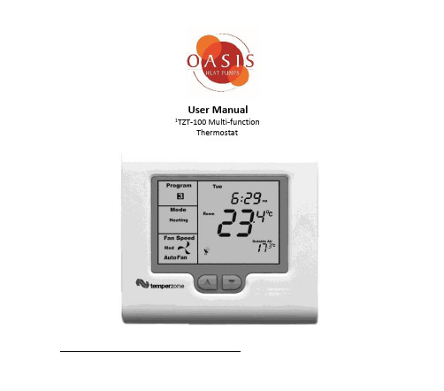
User Manual 1TZT-100 Multi-functionThermostatPlease take time to read and understand these instructions. Doing so will assist you to benefit from the many features offered in this premium product.If properly installed, your thermostat will provide years of trouble- free control of the air temperature within your living or working environment.The TZT-100 thermostat has been designed and built by Smart Temp Australia P/L, to be an attractive, highly reliable and an easy to use thermostat. The TZT-100 model is a modified version of a standard Smart Temp product. It has been configured specifically to Oasis Heat Pumps requirements for use on Oasis Heat and Chill Heat PumpsCare has been taken in the preparation of this manual. However, Oasis takes no responsibility for errors or omissions in this document. It is the responsibility of the user to ensure this thermostat and the equipment connected to it, is operating to theirspecifications, and in a safe manner.Due to ongoing product improvement Smart Temp Pty. Ltd., Oasis. reserve the right to change the specifications of this thermostat (or its components) without notice. . Any such changes may impact upon the operational detail described in this manual. The user should ensure they are reading documentation which relates to the version of thermostat they have..Table of ContentsIntroductionCommercial Programmable modeOn / Off and Mode SelectionSetting the ClockProgramming Your 2 Daily Events9After Hours Rn TimerManual modelOn / Off and Mode SelectionSetting the Fan FunctionSetting the ClockSetting Your Desired TemperatureSwitching Between Day and Night Set PointsTo Review the Set TemperatureCommon FunctionsThe Buttons Explained – ON/Off and Mode Selection etc Control ModesFan FunctionsThis TZT-100 thermostat is able to be used as a residential programmable thermostat, a commercial programmable thermostat or as a simple to use manual thermostat. Your installer will have set these modes to best suit your individual needs.For clarity, this user manual is broken into the following main sections.Commercial Programmable Mode.Allows programming of 1 “Start” and 1 “Stop” time and temperature per day.Manual Mode. (See page 18 of this manual).Use the MODE button to switch On and Off. No time-related programming available.Common Functions - All modes..Commercial Programmable ModeOn /Off and Mode SelectionTap the “MODE” button to cycle the thermostat throughthe available modes: “Heat” only, “Cool” only, Auto-changeover (Shown by both “Heat” & “Cool” in the LCD),Emergency Heat (if fitted), and “OFF”. If the fan mode isset to “Fan On”, when you select “OFF” mode the f anmode will automatically change to “Auto Fan” to preventthe fan from running unexpectedly while the unit is OFF.(Note – Not all modes may be active on your thermostat). Setting the ClockThe thermostat is fitted with a real time clock. This clock is used by the thermostat for the programming functions as described below.It is essential that the clock time and day are set accurately if you require your programmed events to start on time.To set the clock, tap the “PROG”button. The LCD will show the hours digit flashing. Use the up ()or down ()button to adjust the hours to the correct time(note the AM / PM symbol). Tap the “PROG”button again and now the minutes digits will flash.Adjust this value using the up ()or down ()button to show the correct minute. Tap the “PROG”button again and now the weekday flashes, again use the up ()or down () button to set this value to the correct day of the week. Tap the “PROG”button again to exit the clock set function.Programming Your 2 Daily EventsCommercial programming of the thermostat has been designed to be an extremely simple and logical process. The thermostat permits you to program a START time for the air conditioning system, then a Stop time for each day of the week. When the thermostat i s displaying “START” in the LCD, it will maintain whatever set point has been chosen. When the thermostat is displaying “STOP”in the LCD it will be OFF (or it will maintain an energyefficient overnight temperature if set by the installer).To enter the program mode:Press and hold the “PROG” button for 3 seconds. Thedisplay will change to show the Day “Monday” flashing.Using the up()or down()buttons adjust the dayto the day you wish to start programming an event or tothe day you wish to edit an existing event.Tap the “PROG” button to advance to the next step, TheLCD will show the word “START” with the hour’s digiting the up ()or down ()buttons adjustthe hours value to the time you wish the building AirConditioning system to start.Tap the “PROG” button again, now the minute’s digitsing the up ()or down ()b u t t o n s set theminute to the time you wish the building air conditioningsystem t o “START” for the currently selected day.Tap the “PROG” button to advance to the next step, The LCD will show the word “STOP”with the hour’s digit ing the up ()or down ()buttons adjust thehours to the time you wish the building air conditioningsystem to “STOP” for the currently selected day.Tap the “PROG”button again, now the minute’s digitsing the up ()or down ()b u t t o n s set theminute to the time you wish the building airconditioning system to “STOP” for the currentlyselected day. The LCD will now show the word “COPY”.You now have TWO optionsOption 1 - Continue programming as above.Simply continue to tap the “PROG” Button as you have been previously to advance to thenext day, “Tuesday” in this example “START” then “STOP” times, then Wednesday, Thursday etc, following the same simple steps previously explained….OROption 2 –“Copy” ProgramTo copy the values you have just set to other days of theweek tap the up()or down()buttons to“T A G”eachadditional day you wish to copy the currently set daysprogram to. When you have finished “Tagging” the daysyou desire press the “PROG”button to initiate the copyprocess. The word “Copy” will flash briefly to confirm thecopy process and your current days values will be copiedto the days selected. Normal programming will resume atthe next day to be programmed.Please Note –Your thermostat’s programs may be controlled from a Building Management System (BMS) thereby overriding any program you may have entered, as described ab ove. If the BMS is controlling the thermostat the word “Start” or“Stop” will flash in the LCD to indicate the thermostat program is under BMS control.After Hours Run TimerFor convenience, the installer may have set the after-hours run function. This function permits you to temporarily turn the thermostat back on for an installer pre-set period of time if the “Stop” program is running, at the conclusion of which the thermostat will automatically turn back off again.To activate the after-hours run timer, simply tap the“O/RIDE” button. (Or, the optional “After Hours” runbutton on the remote room temperature sensor.) The LCDwill show the word “Override” flashing in the LCD.You can cancel any unexpired portion of the timer periodby tapping the “O/RIDE” button again. The word“Override” will vanish from the screen.To Review the Set Temperature:Simply tap the up ()or down ()button to first turn the LCD backlight t h e n again to display the currently set temperature.Your Installer may have set a default “Start” event temperature that will be used at the commencement of each day; this will override any previous day’s temperature adjustments.Manual ModeON / OFF and Mode SelectionTap the “MODE” button to cycle through all the availablemodes: “Heat”-only, “Cool”-only, Auto-changeover (Both“Heat” & “Cool” show in the LCD at the same time),Emergency Heat (if fitted), and “OFF”. If the fan mode isset to “Fan On”, when you select “OFF” mode, the fanmode will automatically change to “Auto Fan” to preventthe fan from running unexpectedly while the unit is OFF.(Note – Not all modes may be active on your thermostat). Setting the Fan FunctionDetail of the thermostat’s fan control functions can be found on page 26 of this manual. Setting the ClockThe thermostat has a real time clock. In Manual mode, this clock has no function other than to display the time. The clock display can be disabled by the installer if desired.To set the clock, press and hold the “PROG”button for 3 seconds. The LCD will show the hours digit(s)e the up()or down()button to adjust t h e hours to the correct time (note the AM / PM symbol). Tap the “PROG” button and now the minutes digits will flash.Adjust this value using the up()or down()button to show the correct minute.Tap the“PROG”button and now the week day e the up ()or down () button to set this value to the correct day of the week.Tap the“PROG”button again to exit the clock set function or simply wait 30 seconds to auto exit this screen and return to the main operating display.Your clock is now set.Setting Your Desired TemperaturePress and hold the up ()or down ()buttons for3seconds.The t h e r m o st at display will change to show the word “SET”, and the active set point for the current mode. (Heating or Cooling)as you hold the up ()or down ()buttons the current set point will change accordingly.If Auto mode is selected (Indicated by both “Heat” & “Cool” showing on the display at the same time); after adjusting the “Heat” set point, wait without touching a button for 3 seconds. The thermostat display will change to show “Cool”, “SET” and your curr ent cooling set temperature.If desired change this value with the up ()or down () buttons.Wait for another3seconds for the thermostat to automatically exit this temperature setting screen. Your new set temperatures will be maintained.Switching Between Day and Night Set PointsIf the function is set by your installer, the thermostat will keep two sets of temperatures in its memory. Typically one set is for daytime set point temperatures, and the other for the night settings.The thermostat provides a quick and simple way to change between your day and night time set temperatures. Simply tap the “PROG” button. The display will change, showing “Day” or “Night” in the top left hand corner as you switch between modes.Set the “Day” set temperature(s), separately from the “Night”. Each are set as described on the previous page.To Review the Set Temperature:Simply tap the up ()or down ()button to first turn the LCD backlight t h e n again to display the currently set temperature.Common FunctionsThe Buttons Explained – ON/Off and Mode Selection etcMODETap this button to cycle the thermostat through the available modes: “Heat” only, “Cool” only, Auto-changeover (Indicated by the wo rds; “Heat” and “Cool” being visible on the display at the same time), Emergency Heat (if fitted), and “OFF”. When setting the thermostat to “OFF” mode, the fan mode will automatically change to “Auto Fan” mode so the fan does not unexpectedly continue to run.(Note – Not all modes may be active on your thermostat.)O/RIDE (Override)Commercial Programmable Mode:This button initiates the after-hours run timer. When activated, the thermostat will temporarily replace the “Stop” program temperatures with the “Start” program temperatures for an installer-defined pre set period.Residential Programmable Mode:The “O/RIDE” button is used to override the current “event” time scheduling, and to hold the currently set temperature indefinitely. This set temperature will be maintained until released by tapping the “O/RIDE” button again. “Hold” will be displayed in the LCD to confirm this function is active.(Up)Use this button to increase the desired room temperature for “Heating” or “Cooling” modes, or to increase a “value” in programming modes. Also used to force an override of the pre-programmed temperatures and temporarily replace them with a new higher set temperature.(Down)Use this button to decrease the desired room temperature for “Heating” or “Cooling” modes, or to decrease a “value” in programming modes. Also used to force an override of the pre-programmed temperatures and temporarily replace them with a new lower set temperature.PROG (Program)In Residential or Commercial Programmable mode:Tap the “PROG” button to begin setting the clock. Press and hold the “PROG” button for 3 seconds to begin programming your daily e vents.In Manual mode:Tap the “PROG” button to switch between “Day” & “Night” modes. P ress and hold the “PROG” button for 3 seconds to begin setting the clock.Control Modes:Heat-only Mode - The thermostat will turn on the Heating when the room temperature falls below the Heat set point temperature. In Heat-only mode the thermostat will NOT bring on the Cooling regardless of the room temperature and the Cooling set point temperature. In Heat-only mode, only the word “Heat” will be displayed in the LCD. When your thermostat is calling for heat, the word “Heating” will b e displayed.If the word “Heat” is flashing, the thermostat is performing an Anti-Rapid-Cycle safety delay prior to restarting the heating cycle.E. Heat Mode - The thermostat will only use your emergency heating device to maintain your desired heating temperature. This method of heating can be quite expensive therefore Emergency Heat mode is not recommended unless it is essential. When your air conditioning system is heating using emergency heat, the word “E.Heat” in the LCD will change to the word “E.Heating”.Cool-only Mode - The thermostat will turn on the Cooling when the water temperature rises above the Cool set point. In Cool-only mode the thermostat will NOT bring on the Heating regardless of the water temperature and Heating set point temperature. In Cool-only mode, only the word “Cool” will be displayed in the LCD. When your heat pump system is cooling, the word “Cooling” will be displayed.If the word “Cool” is flashing, the thermostat is performing an Anti-Rapid-Cycle safety delay prior to restarting the Cooling.Auto-changeover Mode - The thermostat will turn on the Heating if the water temperature falls below the Heat Set point temperature. Likewise it will commence Cooling if the water temperature rises above the Cool Set point. This is the recommended mode as it provides automatic control of the heat pump system to maintain the desired water temperature. Auto-changeover mode is indicated by both words “Heat” & “Cool” showing in the LCD at the same time.If “Heat” or “Cool” is fl ashing; the thermostat is performing an Anti-Rapid-Cycle safety delay prior to restarting the air conditioning system.Padlock Symbol.Whenever this symbol is shown, a control limit has been reached, or a button,or other function has been locked out.Spanner Symbol.If you see a spanner ICON flashing on your LCD, the installer has left yourthermostat in “Commissioning mode” Although your thermostat will operateyour heating and cooling system whilst in “commissioning mode”, all activesafety and energy conservations delays have been disabled. It is thereforeHIGHLY recommended that you contact your installer and request that theinstaller mode be disabled.Satellite SymbolThis indicates that your thermostat is receiving or sending information toanother “communicating” controller, or a Building Management System.Information received from the building supervisory control system maychange the function (mode or set temperature) of the thermostat. This isnormal and no cause for concern.The intent of this communications is to permit the centralised control of building functions which can include building climate control. To achieve this the BMS must be able to override thermostat settings made by the user. This ability is especially useful when a large facility has a number of heat pumps.TEXT “Locked”:The temperature of the outside air can initiate, or prevent certain functions within the thermostat from operating. If this happens, the word “LOCKED” appears. These functions automatically “unlock” once the outside air temperature becomes favourable. TEXT “FAULT”The TZT-100 has been “requested” to shut down the heating, cooling or heat pump system as a response from an external command. This request may have come from a sensor fitted to the heat pump system, a sensor monitoring supply power or a multitude of safety interlocks that can be used. To clear this fault a service call to your service person may be necessary.Remote Temperature Sensors:Your thermostat is fitted with an accurate and reliable temperature sensor used to measure the water temperature. There may be occasions where the thermostat cannot be placed in an ideal location for water temperature measurement; therefore the installer may have fitted “remote temperature sensor(s)”. These sensors will then report the water temperature from the remote temperature location back to the thermostat where this temperature will be displayed on the LCD.If your thermostat is used in a commercial location, your water temperature sensor may be fitted with a button which activates the “After Hours” run function. Consult your installer if you require this feature or have questions about its use.Symptom Suspected Fault Suggested remedyTemperature display seems inaccurate Sensor location needs to be checked Make sure sensor is in correct position Position of sensor in titanium pocket Make sure sensor is at the bottom of thetitanium pocketSensor calibration may be incorrect Call your installer, Smart Temp or Oasis, forinformation on how tocalibrate the air temperature sensorA remote temperature sensor may be in use. The temperature is NOT being measured atthe thermostat location. The remotelocation may have a different temperature.“Locked” appears on LCD. Heating or Cooling will not operate. This is not a fault.Outside air temp too high to permit heatingOutside air temp too low to permit cooling.Heating and/or cooling disabled to conserveenergy. The heating or cooling function canbe disabled when the outsidetemperature is warm or cool enough to notwarrant the use of the heat pumpController has no display Check main fuse Reset Circuit breakerCall an approved service agent. Faulty Wiring Call an approved service agent.Heat Pump System seems to run all the time Heating and/or cooling temperatures set to anun-achievable value.Set a lower heat temperature and/or ahigher cooling temperature. Review manualon setting temperaturesHeat-Cool System set to Heat Pump Mode Installer setting Incorrect – call for serviceSpanner Symbol in the LCD flashes all the time Installer has left the thermostat in“Commissioning mode”Contact your installer and request“Commissioning mode” be disabled.TroubleshootingSpecificationsInput Voltage 24VAC 50/60 Hz +/- 15%.Relay rating 24VAC @ 1Amp maximum per r elay.Operating Temperature 0-50°C (32 to 122°F).Operating RH 0-95% (non condensing).Storage Temperature 0-65°C (32 to 150°F).Size 113 x 103 x 23mm.Display Size 74 x 55mm.Temperature Sensor(s) 10K NTC type 3.Memory type Non volatile – Settings do not require battery backup. Accuracy +/- 0.3°C @ 25°C. (77°F)Stage Delays Minimum temperature change + time m ethod. Maximum stages controlled 2 cool & 3 heat (Installer s electable)Fan Speeds controlled 1 or 3 (Installer s electable)Timed upstage Delay 5~90 minutes (installer adjustable).Anti-Rapid Cycle Delay Installer selectable –“Off”, or“4-minutes”. Maximum hourly cycles Unlimited, 30, 10 or 6. (Installer s et)Display resolution 0.1 deg C (0.2F).Control Range Off to 45c (113F).Outside Air temp display range -8 ~ +60c (17 ~ 140F).Security Pin protected Installer menu with key l ock.Heat & Cool set control limits.Lithium backup battery for clock functions.Back light Blue EL.Backlight life 3,000 hours to half brightness.Optimised Start/Stop method Time-to-Start v Temp Differential method - updating. Communications Protocol Modbus RTU 4.8K 9.6K 19.2K No parity 1 data 1 stop.– Contact Oasis for Modbus objects l ist. “Auto Fan” speed selection method Difference between room and s et temp. Approvals FCC (Part 15) (pending), C-tick.Battery type CR 1220 (Backs up clock only)Battery life > 5years (10 years Maximum)Oasis Technologies LtdPh 09 5358891Mobile 021 725651Email:*********************************** © Oasis – All rights reserved.Intellectual Rights apply。
鼎捷ERPT100主要功能模块说明
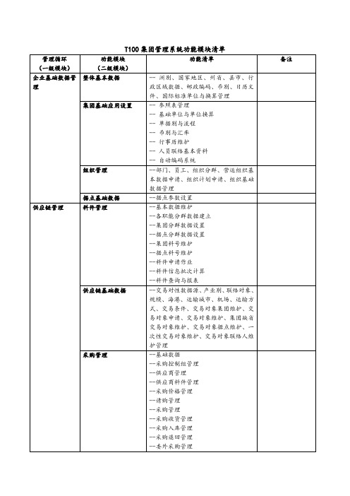
--委外管理
--月底批次处理
--生管查询程序
--生管应用报表
重复性生产管理
--重复性生产基本资料
--生管控制组管理
--生产计划管理
--领退料管理
--重复性生产报工
--完工入库管理
--重复性委外管理
--月底批次处理
--查询程序
--应用报表
可选
项目式生产管理
--项目制造
可选
品质管理
--品管参数设置
APS版本设置与执行
--APS版本维护、APS供需条件设置、APS计算、APS产生请购、APS产生工单、APS订单需求转单作业、APS工单变更整批调整作业、采购变更整批调整作业、请购变更整批调整作业、APS手调器、APS仿真结果查询
采购预测计划管理
--采购预测编号、APS转采购预测作业、采购预测数据维护与打印
生产制造管理
制造基础数据管理
--生管控制组、班别维护、组别维护、组别成员数据、组别行事历维护、员工应投入工时维护
产品结构管理(BOM)
--借用研发管理下模块
制程工艺管理
--借用研发管理下模块
批次生产管理
--批次生产基础数据
--生管控制组管理
--工单管理
--工单派工
--批次生产领退料管理
--批次生产报工管理
--购物篮分析
--会员服务管理
可选
配销管理
--基本数据
--商品管理
--经销商管理
--配销价格管理
--配送派车管理
-潜客管理
可选
财务会计管理
集团财务基础数据规划
--会计基础设置
--交易条件设置
--帐务各中心设置
t100 中insert 用法
t100 中insert 用法一、概述T100是一款常用的数据库管理系统(DBMS),其中的insert语句用于向数据库表中插入新的数据记录。
insert语句可以将指定的数据插入到表中指定的位置,以便在表中添加新的数据。
二、语法结构insert into table_name (column1, column2, column3, ...) values (value1, value2, value3, ...)。
其中,table_name是要插入数据的表的名称,column1, column2, column3等是要插入数据的列的名称,value1, value2, value3等是要插入的数据的值。
三、使用方法1. 确定要插入数据的表和列:首先,您需要确定要插入数据的表的名称和要插入数据的列的名称。
2. 准备要插入的数据:根据要插入数据的列的名称和类型,准备要插入的数据。
数据应该符合数据库表的列的数据类型和格式要求。
3. 使用insert语句:在T100中,使用insert语句将数据插入到表中。
将表名和列名以及要插入的数据值作为参数传递给insert语句。
4. 执行insert语句:执行insert语句,将数据插入到表中。
四、示例假设有一个名为"customers"的表,包含"name"、"age"和"email"三列。
现在要向该表中插入一条新的数据记录,可以使用以下insert语句:insert into customers (name, age, email) values ('John Doe', 25, '****************');执行该语句后,将在"customers"表中插入一条新的数据记录,记录中的数据为'John Doe', 25和'****************'。
1.系统管理-v1-T100

帮 助
相 关 档 离 开 作 业
追 踪
P.34
窗体作业-单据状态
数据状态用一个图标与一个下拉式选单字 段呈现 查询时可以透过下拉式选单字段进行QBE 点选状态图标会显示当下可执行的状态 action
P.35
窗体作业-数据异动信息页签
统一放数据异动的记录信息 纪录最后异动的log 当单据有确认功能时,会多呈现确认者与 确认日期字段 当单据有过账功能时,会多呈现过账者与 过账日期字段
P.10
企业集团规划
企业架构 支持多个企业集团在单一数据库作业
企业总部
建立新的企业集团时,会自动汇入基本数据 建立新的企业集团时,会预设产生一个SITE-01的据点, 一个企业可以建立多个据点。
子公司
子公司
企业
98 重庆光大产业
据点
工厂 分公司
01重庆光大
02重庆光昊
门市
P.11
数据库架构
P.39
单据别
单据别 期别与流水 1 2 3 4 5 6 7 8 9 0 1 2 3 4 5 6 7 8 9 0 据点代码
可指定单号总长度(最长20码) 可指定据点代码长度(最长5码) 可指定单别长度(最长5码) 可指定单别在据点前或据点后 可指定是否要有分隔符 “-” 单据别中设定期别流水原则
用户数据设置 azzi800
权限角色配置 Action权限设置 资料权限设置 动作设置 范围设置 字段权限设置 1.人员间资料 2.部门间数据 3.部门群组间数据 可拜访据点
部门数据权限配置
1.新增 2.查询 3.修改 4.删除
P.19
权限管理-特色
一个用户可以同时拥有有多个职能角色的权限 同一个用户在不同的据点可以有不一样职能角色的权限
TTI-120E齿轮测试仪操作手册
作者简介:赵红荣:齿轮爱好者,1997年至2009年底在深圳一家大型精密五金厂任职,2010年初至今在珠海一家大型机电有限公司任职,对齿轮颇感兴趣,对国内外多种滚齿机、齿轮检测仪器都了解(宁江Y3612/1、瑞士M I K R O N102、日本H A M A I120、60S P、60S P-N C、H O B L O N-8F、H B-300、德国K P-200、瑞士M Z-130、日本T T I-120、C L P-350、德国P26)。
由于对齿轮的热爱,本人将所学到的知识、技能以文字方式叙述出来,供初学者参考借鉴,本人汇编了《齿轮原理手册》、《滚刀知识总汇》、《蜗杆知识》、《K P-200操作手册》、《M Z-130操作手册》、《H A M A I G N-150C N C修刀机操作手册》、《H A M A I60S P-ⅡN C滚齿机操作说明》、《T T I-120E齿轮测试仪操作手册》等。
简洁实用的操作手册及理论知识,希望能帮到齿轮初学者。
我相信,中国制造的齿轮会在不久的将来超越其它强国,到处都会见到m a d e i n C h i n a。
同时为给齿轮爱好者提供一个学习交流的平台,请登录注册:中国齿轮论坛,上面汇集齿轮各方面资料和许多前辈、专家,都与你在线交流,为你解答实际遇到的困难。
最后,原我的一些资料能帮到大家。
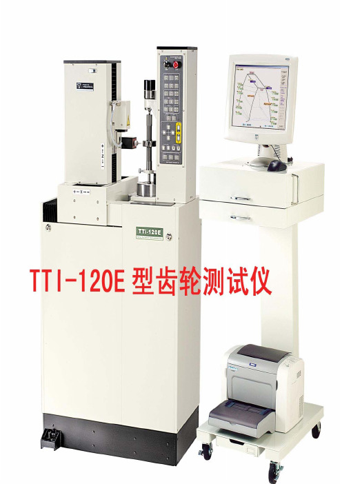
联系Q Q:113616438邮箱:z h a o h o n g r o n g@s o h u.c o m一、TTI齿轮测试仪的启动和关闭1.启动1)打开主电源、稳压器、开启电脑、拔出紧急开关按钮、测试仪钥匙打开;Windows启动后,双击TTI NC齿轮测试仪的快捷键(有些电脑开机后会2)TTI自动进入);3)齿轮测试仪的主菜单画面启动;4)按齿轮测试仪上闪烁绿色灯(基点),让其机械部分自动原点复归。
现在,齿轮测试仪程序及机械部分已全部启动。
图一:主程序画面2.关闭选择测试仪程序关闭(System Finish and Go to Windows);1)System Finish and Go to2)选择YES;3)结束程序回到WINDOWS桌面4)按下紧急开关按钮,测试仪钥匙关闭。
T100中文操作指南
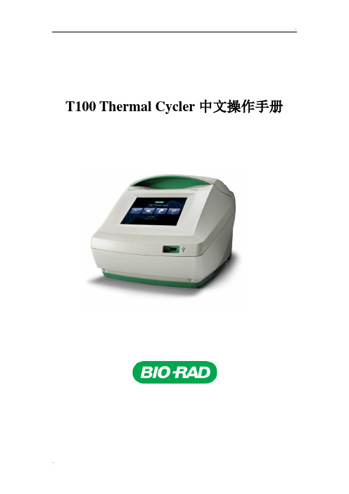
T100中文操作指南(总19页)--本页仅作为文档封面,使用时请直接删除即可----内页可以根据需求调整合适字体及大小--T100 Thermal Cycler中文操作手册手册内容1 工作环境2 T100 Thermal Cycler的介绍3 T100 Thermal Cycler 创建、编辑和储存程序4 运行程序5 管理文件夹和反应程序文件6 工具7 仪器日常维护1 工作环境工作温度 15-31℃工作和存储湿度20-80%工作电源 100–240 VAC (±10%), 50–60HZ.PCR许可证有2 T100 Thermal Cycler的介绍T100 Thermal Cycler 各部分简介T100 Thermal Cycler具有96孔的反应模块,可以使用标准96孔板、联管或单管等多种耗材。
仪器支持的样品反应体积为1-100ul, 推荐的反应体积为15-50ul。
仪器主要包括以下几个部分:加热模块:放置装有样品的标准96孔板、联管或单管热盖:加热样品管的顶部,防止样品蒸发和冷凝触屏:用于反应程序的编辑、修改和运行,实时显示运行程序USB接口:外接USB,导出数据LED指示灯:仪器正常运行时,指示灯亮散热口:提供通风,用于仪器的快速升温和降温触屏仪器开机后,显示触屏界面,界面提供仪器的名字,日期和时间,触屏上的四个按键分别代表的意义如下:New Protocol:创建一个新的反应程序Saved Protocols:查看、编辑、运行储存的程序Incubate:可长时间运行一个恒定的温度,与水浴锅功能相似Tools:设置、仪器自检、仪器信息、软件升级放置样品向上打开仪器热盖,将样品管放到相应的位置,合上热盖。
热盖的主要功能是在程序运行时,加热样品管的顶部,防止样品蒸发和冷凝。
放置样品管时,要确保管子与反应模块完全接触,且反应模块必须完全干净。
3 T100 Thermal Cycler 创建、编辑和储存程序创建新的程序,点击触屏界面的“New Protocol”按钮,进入编辑界面。
T100中文操作指南
T100 Thermal Cycler中文操作手册手册内容1 工作环境2 T100 Thermal Cycler的介绍3 T100 Thermal Cycler 创建、编辑和储存程序4 运行程序5 管理文件夹和反应程序文件6 工具7 仪器日常维护1 工作环境1.1 工作温度15-31℃1.2 工作和存储湿度20-80%1.3 工作电源100–240 V AC (±10%), 50–60HZ.1.4 PCR许可证有2 T100 Thermal Cycler的介绍2.1 T100 Thermal Cycler 各部分简介T100 Thermal Cycler具有96孔的反应模块,可以使用标准96孔板、联管或单管等多种耗材。
仪器支持的样品反应体积为1-100ul, 推荐的反应体积为15-50ul。
仪器主要包括以下几个部分:⏹加热模块:放置装有样品的标准96孔板、联管或单管⏹热盖:加热样品管的顶部,防止样品蒸发和冷凝⏹触屏:用于反应程序的编辑、修改和运行,实时显示运行程序⏹USB接口:外接USB,导出数据⏹LED指示灯:仪器正常运行时,指示灯亮⏹散热口:提供通风,用于仪器的快速升温和降温2.2 触屏仪器开机后,显示触屏界面,界面提供仪器的名字,日期和时间,触屏上的四个按键分别代表的意义如下:⏹New Protocol:创建一个新的反应程序⏹Saved Protocols:查看、编辑、运行储存的程序⏹Incubate:可长时间运行一个恒定的温度,与水浴锅功能相似⏹Tools:设置、仪器自检、仪器信息、软件升级2.3 放置样品向上打开仪器热盖,将样品管放到相应的位置,合上热盖。
热盖的主要功能是在程序运行时,加热样品管的顶部,防止样品蒸发和冷凝。
放置样品管时,要确保管子与反应模块完全接触,且反应模块必须完全干净。
3 T100 Thermal Cycler 创建、编辑和储存程序3.1 创建新的程序,点击触屏界面的“New Protocol”按钮,进入编辑界面。
T100固定资产管理手册教程AFA

盘盈建卡
盘点后根据盘点差异表,对盘盈资产建卡
调入建卡
根据资产调入单进行固定资产建卡
P.12
资产取得流程
资产资本化
直接资本化
在建工程
对于购入即可使用的可以直接行进资本化
对于需要安装、调试和验收竣工的可以先通过在建工程核算,然后等竣工报告后资本化。同时 在资本化之前发生的利息等费用也可以通过在建工程后再资本化进入资产价值中。
请购单 采购单
收货单 入库单
发票
应付账款
资产领用 (杂发)单
利息费用
杂项费用
在建工程
在建 否
资产卡片
P.13
资产折旧
资产折旧
✓ 系统提供按账簿、按期间、按本位币计提资产折旧 ✓ 可以统一计提也可以单个卡片计提 ✓ 系统提供按”资产组”计提折旧 ✓ 如果折旧后发现有误或其他原因需取消折旧,系统支持对已提折旧进行回滚 ✓ 支持资产价值、使用年限、折旧方法、工作总量变动是否影响当期折旧 ✓ 系统提供多种折旧方法。
TOPGP ERP 固定资产管理
课程大纲
1. 固定资产管理模块系统架构 2. 模块重要观念与应用
- 物账分离,一物多账 - 基础数据设定
3. 重要流程
- 资产取得流程 - 折旧计提管理 - 资产异动金管理系统架构关连图
采购管理
资产请采购
应付帐款 立帐及付款 模块
• 组织内调拨 • 跨组织移转并产生应收、应付
P.5
资产管理组织
集团
公司A
公司B
资产中心2
生产厂一
资产中心1
营销外点
华南区
营销外点
部门
部门
➢ 统筹多个结算单位(法人)的资产统一管理。 ➢ 中心是具有“资产组织”的组织单元才能
- 1、下载文档前请自行甄别文档内容的完整性,平台不提供额外的编辑、内容补充、找答案等附加服务。
- 2、"仅部分预览"的文档,不可在线预览部分如存在完整性等问题,可反馈申请退款(可完整预览的文档不适用该条件!)。
- 3、如文档侵犯您的权益,请联系客服反馈,我们会尽快为您处理(人工客服工作时间:9:00-18:30)。
T100 Thermal Cycler中文操作手册手册内容1 工作环境2 T100 Thermal Cycler的介绍3 T100 Thermal Cycler 创建、编辑和储存程序4 运行程序5 管理文件夹和反应程序文件6 工具7 仪器日常维护1 工作环境1.1 工作温度15-31℃1.2 工作和存储湿度20-80%1.3 工作电源100–240 V AC (±10%), 50–60HZ.1.4 PCR许可证有2 T100 Thermal Cycler的介绍2.1 T100 Thermal Cycler 各部分简介T100 Thermal Cycler具有96孔的反应模块,可以使用标准96孔板、联管或单管等多种耗材。
仪器支持的样品反应体积为1-100ul, 推荐的反应体积为15-50ul。
仪器主要包括以下几个部分:⏹加热模块:放置装有样品的标准96孔板、联管或单管⏹热盖:加热样品管的顶部,防止样品蒸发和冷凝⏹触屏:用于反应程序的编辑、修改和运行,实时显示运行程序⏹USB接口:外接USB,导出数据⏹LED指示灯:仪器正常运行时,指示灯亮⏹散热口:提供通风,用于仪器的快速升温和降温2.2 触屏仪器开机后,显示触屏界面,界面提供仪器的名字,日期和时间,触屏上的四个按键分别代表的意义如下:⏹New Protocol:创建一个新的反应程序⏹Saved Protocols:查看、编辑、运行储存的程序⏹Incubate:可长时间运行一个恒定的温度,与水浴锅功能相似⏹Tools:设置、仪器自检、仪器信息、软件升级2.3 放置样品向上打开仪器热盖,将样品管放到相应的位置,合上热盖。
热盖的主要功能是在程序运行时,加热样品管的顶部,防止样品蒸发和冷凝。
放置样品管时,要确保管子与反应模块完全接触,且反应模块必须完全干净。
3 T100 Thermal Cycler 创建、编辑和储存程序3.1 创建新的程序,点击触屏界面的“New Protocol”按钮,进入编辑界面。
3.2 也可选择编辑储存的程序,点击触屏界面的“Saved Protocols”按钮,选择一个程序,点击“Edite”,进入编辑界面。
3.3 新的程序编辑界面打开,如图所示3.4 按照需要的实验程序,首先设置反应体积,在V olume 中输入体积数,可输入范围为1-100ul, 推荐反应体积为15-50ul。
其次设置热盖的温度,在Lid中输入温度,可输入范围为40-110℃,推荐温度为105℃。
最后,点击反应程序的每一步时,显示为绿色,分别设置该步反应的温度和时间。
点击温度按钮,如95℃,出现数字键盘,输入需要的温度,点击“OK”,确认。
同样的操作编辑时间。
“GOTO”可以设置反应的循环数,如“34X”,即共35个循环,也可设置循环的起始反应步骤,如“Step2”,即循环反应从第2步开始至第4步结束,箭头指示的过程。
3.5 插入新的反应步骤,点击一个步骤,显示为绿色,点击“Insert”将在该步骤后面插入新的反应步骤。
在“Insert Step”界面选择需要插入反应步骤的类型,“Temperature”即可插入温度反应, “Gradient”即可插入温度梯度反应, “GOTO”即可插入PCR循环反应。
点击“Delete”,即可删除选择的步骤。
3.6 添加或删除温度梯度。
选择一个反应步骤,点击“Options”, 进入步骤优化窗口。
选择“Gradient”,在“Back row”输入温度梯度的最高温度,在“Front row”输入温度梯度的最低温度,右边会显示从A到H每一行的温度值。
注意:该仪器温度梯度跨度范围为1-25℃。
点击“OK”,返回程序主界面,最低和最高温度的温度梯度显示在反应步骤中,可以点击温度,直接修改温度梯度,不用再进入“Option”。
3.7 温度的递增、时间的延伸和改变升温速率。
选择一个反应步骤,点击“Options”, 进入步骤优化窗口。
每一个实验步骤都包括“Increment”、“Extend”、“Ramp Rate”,“Increment”输入X,即每个循环后温度增加X℃,“Extend”输入Y,即每个循环后时间延长Y秒,“Ramp Rate”输入Z,即升温速率为Z。
点击“OK”,确认。
3.8 改变“GOTO”参数。
“GOTO Step”表示多个步骤的重复循环反应。
选择一个“GOTO Step”,点击“Step”按钮,进入数字键盘,修改数字为X,即可决定循环反应的起始步骤为X,如“Step2”,即循环反应从第2步开始至第4步结束,箭头指示的过程。
点击“X”按钮,进入数字键盘,修改数字为Y,即表示再重复Y个循环,总循环数为Y+1, 如“34X”,即共35个循环。
3.9点击“Run”,无需储存,直接运行编辑好的反应程序。
也可点击“Save”按钮, 进入储存界面,在Folder后输入或选择储存程序的文件,在Name后输入反应程序命称,点击“Save”,返回程序主界面。
然后点击“Run”,运行程序。
4 运行程序4.1 开始运行程序,有如下方法:●创建新的程序,点击“Run”●从“Saved Protocols”中选择程序,点击“Run”●从“Saved Protocols”中选择程序,点击“Edite”,修改后,点击“Run”前面已经详细介绍了创建和编辑新的反应程序,下面介绍从“Saved Protocols”中选择程序,运行。
首先从开机界面中,点击“Saved Protocols”,进入选择界面。
其次从“Folders”文件夹中选择文件,如“MAIN”。
再次选择“Files”文件中的反应程序,如“ISCRIPT”,“Preview”中会显示所选程序的详细设置,包括每一步的反应温度和时间等信息。
选择好程序后,点击“Run”,出现对话框,询问是否修改反应体积,点击“OK”直接运行程序,或者点击“Volume”修改体积后,再运行程序。
程序运行后,运行进程可以通过两种状态显示,分别是“Status”和“Clock”。
“Status”状态显示整个实验程序的每个步骤,以及正在进行的步骤。
“Clock”状态显示整个实验程序的剩余时间。
点击“View Status”和“View Clock”,可在二者之间进行自由切换。
4.2 暂停和恢复程序运行一个PCR反应程序允许暂停的,暂停时,加热模块会维持在当前实验步骤的反应温度,热盖也维持原本的温度,直到反应程序恢复继续运行。
当正在升温或降温时,程序暂停,仪器会继续升温或降温,直到到达设定的温度,才会保持不变。
在“Status”状态时,点击“Pause”按钮,反应程序暂停。
点击“Resume”按钮,反应程序继续运行。
4.3 跳过反应程序中的某一步,可以缩短反应时间。
在在“Status”状态时,点击“Skip Step”按钮,即可跳过当前步骤,多次点击“Skip Step”按钮,即可跳过多个步骤。
4.4 取消反应程序。
当程序取消时,加热模块立刻停止温度加热。
不要立即关闭仪器电源,仪器需要时间使加热模块降温。
在在“Status”状态时,点击“Cancel”按钮, 选择“Yes”确认。
4.5 孵育功能。
开机主界面,点击“Incubate”按钮,进入孵育功能界面。
编辑“Block temperature”,输入温度值,即设置孵育温度。
编辑“Hold time”,输入时间,即设置孵育时间,也可设为无穷时间。
编辑“Lid temperature”,输入温度值,推荐105℃保持热该温度,防止样品蒸发或冷凝。
点击“Run”,运行孵育程序。
结束孵育功能时,点击“Cancel”。
5 管理文件夹和反应程序文件开机进入主界面,点击“Saved Protocols”,进入选择界面,包括以下文件夹:●MAIN folder:仪器自带的一些标准反应程序,可以编辑、删除和重命名●RECENT folder: 储存的是最近使用过的20个程序●CUSTOM folder:可以设置为实验室成员的个人文件夹●USB folder:外接SUB里的反应程序5.1 新建文件夹,从“Saved Protocols”选择界面,点击“Folder Options”,选择“New”,输入8个字节的名称,点击“OK”,完成。
5.2 复制文件夹或文件,从“Saved Protocols”选择界面,选择文件夹或文件,点击“Folder Options”或“File Option”,选择“Copy”,最后选择文件或文件夹新的储存位置,点击“Save”,即可完成。
5.3 删除文件夹或文件,从“Saved Protocols”选择界面,选择文件夹或文件,点击“Folder Options”或“File Option”,选择“Delete”,即可完成完整的文件夹或单个文件的删除。
5.4 重命名文件夹或文件,从“Saved Protocols”选择界面,选择文件夹或文件,点击“Folder Options”或“File Option”,选择“Rename”,输入新的名称,点击“OK”,确认。
6 工具开机进入主界面,点击“Tools”,进入选择界面,包括以下文件夹:●Settings: 仪器的系统设置●Self-Test:仪器自检设置,检测各部件的功能●Logs:观察反应运行程序界面,可以被拷贝到USB●About:观察软件的版本和仪器的机身号●Update Firmware:升级仪器的版本●Service Login:可以从Bio-Rad厂家获得帮助服务6.1 仪器的系统设置,从“Tools”界面,选择“Settings”,进入界面,会看到仪器的系统设置,包括“Cycler name”设置仪器的名称,“Date”设置日期年月日等信息,“Time”设置详细时间信息,“Display brightness”设置显示屏亮度,“sample volume”设置默认的样反应体积,“Standby delay”设置一段时间后,为了节约电资源,仪器会进入待机状态,“End of run beep”设置运行结束后,仪器会发出声音,提醒用户。
6.2 仪器自检功能,从“Tools”界面,选择“Self-Test”,点击“Start”,仪器运行自检程序,检测仪器各部件的性能。
6.3 升级仪器版本,从“Tools”界面,选择“Update Firmware”,点击“Start”,仪器运行升级程序,可升级到最新版本。
6.4 观察软件的版本和仪器的机身号,从“Tools”界面,选择“About”,即可看到仪器版本,机身号和仪器运行的总时间。
7 仪器日常维护●本机适用于实验室任何部位使用,应远离易燃易爆物品,远离水源和离心机等,避免将液体渗入仪器内部,保持仪器工作环境的稳定性●由于本机采用半导体双向控温技术,由机器内风机散热,故不得堵塞仪器两侧及底部的通风口,并应远离热源,保持良好的通风。
