日本IWAKI易威奇_EHN系列电磁计量泵
易威奇(iwaik)MD磁力泵使用说明书

IWAKI AMERICA MAGNETIC DRIVE PUMP MD/WMD SERIESContents1SAFETY INSTRUCTION (1)2UNPACKING AND INSPECTION (3)3OPERATING PRINCIPLE (3)4MODEL IDENTIFICATION GUIDE (4)5SPECIFICATIONS (5)Construction/Materials (6)6HANDLING INSTRUCTIONS (7)7INSTALLATION, PIPING, AND WIRING (8)7.1Installation (8)7.2 Piping instructions (9)7.3Wiring (9)8 ASSEMBLY (11)9OPERATION (12)10 MAINTENANCE/INSPECTION AND CONSUMABLE PARTS (14)11 PARTS DESCRIPTION AND EXPLODED VIEW (14)12 DIMENSIONS (15)13 TROUBLESHOOTING (16)P/N 180243 Rev. C Jan 20101 SAFETYINSTRUCTIONSTurn off the power supplyWorking without disconnecting the power supply may cause an electrical shock. Before performing any assembly or maintenance procedures involving the pump, make sure to turn the power supply switch off and to stop the pump and other related devices.Terminate operationWhen you detect any signs of abnormal operation, terminate pump operation immediately.For specified application onlyThe use of a pump in any applications other than those clearly specified may result in injury or damage to the pump. Use the pump strictly in accordance with the pump specifications and application capabilities.ModificationNever modify the pump. Iwaki America will not be responsible for any accident or damage of any kind caused by the user remodeling the pump without first obtaining permission or instructions from Iwaki America.Protective clothingIf application involves the handling of hazardous liquids, protective gear (gloves, glasses, clothing, etc) must be worn before performing any maintenance on the pump. Please follow safety guidelines established for such applications.OperationOperation of the pump and related system must be by experienced or knowledgeable personal. The pump operator or pump operation supervisor must not allow any personal who have little or no knowledge of the pump to operate the unit.PowerDo not operate the pump at a different voltage than specified on the nameplate. This may result in damage to the unit or fire. Only the specified voltage must be used.Do not submergeIf the motor or power cable becomes wet or damp fire or electric shock may occur. The unit should be installed in such a manner to prevent contact with fluids or in a wet environment. Follow all local, state and government regulations for the installation and wiring of the pump.Spill accidentProtective measures should be taken against any accidental spill or leakage of any hazardous liquids as a result of unexpected damage to the pump or the related piping. Please follow safety guidelines established for such occurrences.Operating site must be free of water and humidityThe pump is not designed to be water-proof or dust-proof. The use of the pump in places with splashing water or humidity above 90% may result in an electrical shock or short circuit.Do not damage power cordDo not cut, abrade or forcibly pull the power cord. Excessive heat or heavy load applied to the cable may damage the cable and finally result in a fire or an electrical shock.Do not cover the motorCovering the motor during operation may result in an accumulation heat inside the motor and cause a fire or a mechanical failure. Proper ventilation is necessary for the motor.GroundingDo not operate the pump without proper grounding; otherwise an electrical shock may result. Follow all local, state and government regulations for the installation and wiring of the pump.Power cord cannot be replacedNever use a damaged power cable; otherwise, a fire or an electrical shock may result. Handle the power cord carefully, as it cannot to be replaced by a new cable. (The complete motor must be replaced if damaged).Location and storageDo not install or store the pump in the following places:* Places where a flammable gas or material is used or stored.* Places where the ambient temperature is extremely high (104°F or higher) or extremely low(32°F or lower).Static Electricity HazardWhen low electric conductivity liquid such as ultra-pure water is handled, static electricity may be generated in the pump, which may cause static discharge and damage the pump. Take appropriate countermeasures to avoid and remove any potential static electricity.2 UNPACKING AND INSPECTIONOpen the package and check that the productconforms to your order. Also, check each of thefollowing points. For any problem orinconsistency, contact your distributor at once.1. Check that the model number indicated on thenameplate conforms to the specifications ofyour order.2. Check that all the accessories you ordered areincluded.3. Check that the pump body and parts have notbeen accidentally damaged or that any boltshave not been loosened in transit.3 OPERATINGPRINCIPLEA sealless magnet drive pump uses magnet torque to transmit energy from the motor to the impeller. A magnet coupling is formed using an inner, or driven magnet, attached to the impeller and an outer, or drive magnet, attached to the motor shaft. This design eliminates mechanical shaft seals or packing, since there is no direct connection between the motor shaft and the impeller. The front and rear casings, sealed with a static o-ring, form the pump or liquid end. The magnetic field is transmitted from the drive magnet through the rear casing to the driven magnet that is attached to the impeller. The combined coupling torque of the drive magnet and impeller magnet provides the driving power to theDrive MagnetDriven Magnet4 MODELGUIDEIDENTIFICATION1 2 3 4 5 6 7 81. Series name (WMD specifies US motor design)2. Pump Size (6, 10, 15, 20, 30, 55, 70, 100)3. R = Rotating Spindle (omit for MD-6 and MD-10)4. L = UL Listed Motor, included in 6, 10, 55, 70, 100 115V model(also on older 15/20/30/40 models)5. Pump typeBlank: Standard ImpellerZ: High Head ImpellerX: High Flow Impeller6. Suction/Discharge Port ConnectionsBlank: Hose ConnectionT: Threaded Connection7. Power source voltage:115: 115V (50.60Hz) 230: 230V (50/60Hz)220:220/240V(50/60Hz)8. NL = UL Listed 115V Motor (applies to 15, 20, 30, 40 sizes)5 SPECIFICATIONSConnections ModelHose NPT MotorOutput (HP) MotorSpeed(RPM)Current(Amps)MaxFlow(GPM)MaxHead(Ft)Max Sys.Pressure(PSI)SpecificGravityWeight(Lbs)PolypropyleneMD-6 1/2---1/25031000.252.3 4.5 2.80 1.2 1.8MD-10 1/2---1/12529000.403.1 6.84.30 1.1 1.6MD-15R(T) 1/21/21/7531000.29 5.0 11.1 7.20 1.3 3.5 WMD-15R(T) 1/21/21/38 3100 0.82 5.0 11.1 7.20 1.3 6.0MD-20RT(T) 5/83/41/38 3100 0.48 8.2 14.1 9.95 1.1 4.4 WMD-20R(T) 5/83/41/38 3100 0.48 8.2 14.1 9.95 1.1 7.0MD-20RX(T) 1 1 1/38 3100 0.50 13.7 8.2 5.69 1.3 4.4 WMD-20RX 111/3831000.5013.7 8.2 5.69 1.3 7.0MD-20RZ 5/83/41/3831000.53 2.9 22.6 14.22 1.1 4.4 WMD-20RZ 5/83/41/383100 0.53 2.9 22.6 14.22 1.1 7.0MD-30R 3/43/41/1631500.80 10.0 17.7 11.60 1.3 7.7 WMD-30R 3/43/41/1631501.00 10.0 17.7 11.60 1.3 9.0MD-30RX 1 1 1/16 3150 1.10 19.0 13.5 8.54 1.1 7.7 WMD-30RX 111/1631501.0019.0 13.5 8.54 1.1 9.0MD-30RZ 5/83/41/1631501.10 4.5 36.1 24.18 1.0 7.7 WMD-30RZ 5/83/41/163150 1.00 4.5 36.1 24.20 1.0 9.0MD-40R 3/43/41/1232001.30 13.7 21.3 14.22 1.1 8.6 WMD-40R 3/43/41/1232001.90 13.7 21.3 14.22 1.1 10.0MD-40RX 1 1 1/12 3200 1.20 22.4 15.4 9.95 1.1 8.6 WMD-40RX 111/1232001.9022.4 15.4 9.95 1.1 10.0MD-55R 1 1 1/8 3400 1.60 18.4 26.9 17.06 1.2 10.1MD-70R 1 1 1/4 3400 2.80 25.6 31.8 21.33 1.0 13.2MD-70RZ 3/43/42/734003.80 11.4 66.6 42.70 1.0 13.2MD-100R 1 1 1/3 3300 3.40 35.6 39.0 25.60 1.2 18.7 WMD-100R 1 1 1/3 3400 * 35.6 39.0 25.60 1.2 * FluoroplasticWMD-30FX ---1/21/163200 0.9 3.2 35.2 17.01.3(1.5)9 WMD-30FY ---1/21/163200 0.9 3.2 26.0 17.01.5(1.8)9 WMD-30FZ ---1/21/163200 0.9 2.6 24.0 21.3 1.9(2.1) 9MD-55Y ---11/833001.917.125.621.31.3(1.5)11.9 MD-55Z ---11/833001.613.0 19.0 21.3 2.0(2.2) 11.9 WMD-100FY --- 1 1/3 3450 * 36.0 38.0 31.2 1.3(1.6) *MD-100FY ---11/333003.435.737.731.21.3(1.6)18.7 WMD-100FZ ---1 1/3 3450 * 28.0 27.2 31.2 1.9(2.2) *MD-100FZ ---11/333003.428.027.231.21.9(2.2)18.7 Notes:1. Pump performance data is based on pumping clean water at ambient temperature.2. The maximum flow rate is at 0 discharge head.3. Maximum viscosity of liquid: 1.0 cP (for a specific gravity of 1.0)4. Permissible liquid temperature: 32-176°F (0 – 80°C). Note, permissible temperature range may differ dependingupon the type of liquid and operating conditions.)5. The maximum specific gravity of the liquid is the value at max. flow rate. The value varies depending on the flowrate, ambient temperature, viscosity of liquid, etc.6. Motor: Single-phase capacitor-run induction motor or 3-phase induction motor.* Built-in thermal protectorA thermal protector is built in the motor. The protector automatically stops motor operation when the motor isoverheated. (The motor starts again when the temperature falls to normal.)Typical Construction/MaterialsName Qty MaterialNo. PartGFRPP (Note 1)1 FrontCasing 1Casing 12 Rear3 Impeller 1Ceramic4 Thrust 2 Alumina5 O-ring 1 FKM or EPDM (Note 2)6 Screw 4~6 Stainless steelcontaining7 Bearing 2 Fluororesinfiller material (Note 3)ceramic8 Spindle 1 Alumina9 Motor 1Note 1: The material of the impeller used in MD-70RZ, 100R, 100R-5 is CFRPP.Note 2: More elastomer options availableNote 3: The material of the bearing used in (W)MD-20RZ, 30RZ, and MD-70RZ is PPS.6 HANDLINGINSTRUCTIONS1. Handle the pump carefullyStrong impact to the pump assembly may result in damage or reduced performance.2. StartingBefore priming the pump be sure the power is turned off then proceed with filling the pumpend with water. Note, the pump must be fully primed before starting.Next close the valve on the outlet or discharge side of pump. Turn on power to the pump,when full speed is reached gradually open the discharge vale until specified flow rate isachieved.CautionOperating the pump dry (without liquid) may cause severe damage.3. StoppingWhen stopping the pump, first close the discharge valve gradually. When it is completelyclosed, turn off the power switch so that the pump stops. Never stop the pump suddenly byquickly closing a valve (i.e., solenoid or hydraulic valves).CautionQuick valve closure may cause water hammer that can cause severe damage to thepump.4. TemperatureThe pump itself may not suffer a change in performance due to temperature fluctuation.However, the liquid may change in terms of viscosity, vapor pressure, and corrosive properties.Pay special attention to changes in liquid characteristics as a result of temperature fluctuation.Liquid temperature range: 32 – 176°F (0 – 80°C)Ambient temperature range: 32 – 104°F (0 – 40°C)5. As there is a powerful magnet inside the pump unit, do not use any liquid that contains metallicsubstances such as iron, nickel, etc.6. Do not operate the pump in the following places:∙ Places exposed to rain and/or wind.∙ Places where the temperature falls below 32°F (0°C).∙ Places where corrosive gas (such as chlorine) is present.∙ Places exposed to splashing of water or fluid being pumped.∙ Places where the ambient temperature is 104°F (40°C) or above.∙ Places where explosive or combustible materials/gases are present.7. Do not operate the pump with the following liquids:∙ For the compatibility to chemical liquid or any special liquid, contact an Iwaki America sales representative.∙ Liquids that significantly swell polypropylene.∙ Paraffinic hydrocarbons such as gasoline and kerosene.∙ Halogenated hydrocarbons such as trichloroethylene and carbon tetrachloride.∙ Ether and low-grade ester∙ Slurry(For a chemical compatibility to guide contact Iwaki America customer service.)8. To prevent fire and explosions, do not place dangerous or flammable substances near thepump.9. Be sure unit is properly ground.10. If a pumped is damaged, it can be dangerous to operate. Contact factory for assistance.11. Avoid direct physical contact with the motor or pump during operation, as surface temperaturesmay be extremely high due to operating conditions.7 INSTALLATION, WIRING AND CONNECTIONS7.1 Installation1. Installation siteInstallation site must have an ambient temperature of 32-104°F (0-40°C) and a relativehumidity lower than 90%. Install the pump where maintenance and inspection work can bedone easily.2. Pump installation methodThis pump is not self-priming. It is recommended that the pump shall be installed in aposition lower than the liquid level of the suction tank by at least 12 inches (30 cm). If thisdistance is too short, air may enter the pump, causing damage.3. Direction of pump discharge portThe discharge port can be directed as desired. However, for efficient elimination of air inthe pump end, it is recommended that the discharge port be positioned in the horizontaldirection.4. Anchoring of baseThe base of the pump must be anchored firmly. The pump must not be mounted in avertical position.7.2 Piping instructions1. To minimize frictional resistance, the shortest piping possible with a minimum number ofbends should be utilized on the inlet or suction side of the pump.2. Use a corrosion-resistant vinyl hose that is rated at or above the pressure rating of thepump (see specification table).3. Hose size (for hose-barb style pumps)Select hose size in accordance with the diameter of the pump connections. As the hosetends to be crushed under the force, the use of a braided reinforced hose is recommended.Note, if the connection on the suction side is loose air may be mixed in with pumped fluid.(In the case of high temperature liquids, special attention must be paid to the selectionof a hose.)4. Hose connectionBe sure to cut the ends of the hose straight. Press the hose end firmly against the dischargeor suction port until it reaches the bottom of the port. Use a fastener (such as a hose clamp)to make the connection tight and leak free.CautionDo not over tighten the connection ports (suction and discharge) excessively asthey are made of plastic resin and are could be damaged.5. Valve installationInstall valves close to the suction and discharge ports.∙ Suction side valve:For easy liquid removal and pump maintenance∙ Discharge side valve:For adjustment of the discharge rate or head and for easy removal and pumpmaintenance.7.3 Wiring1. Prior to wiring the pump, confirm the voltage indicated on the nameplate is correct foryour installation. (Observe all local and national regulations regarding electrical work.)The connection diagram is presented on the next page.2. The pump does not have an external switch. It starts when power is supplied to the pumpwires.Wiring diagrams• (W)MD-15R, 20R, 20RX, 20RZ, 30R, 30RX and 30RZ (Single-phase capacitor run motor withthermal protector)• (W)MD-40R, 40RX, 40RZ, 55R, 70R, 70RZ, and 100R (Single-phase capacitor run motor withthermal protector)• MD-70R, 70RZ, and 100R models (3-phase motor, 220/380V)• (W)MD-70R, 70RZ, and 100R models (3-phase motor,400/440V)8 ASSEMBLY1. Place the motor on end vertically so that the shaft is pointed upward.2. Install the drive magnet on the motor shaft and position the shaft flush with the inside of themagnet. Note: On WMD models, screw the bracket to the motor first.3. Insert the rear casing into the magnet/motor bracket.4. Install the impeller and O-ring into the rear casing.5. Place the front casing over the pump, making sure that the volute casing is aligned.6. Using a hex head driver, fasten the liquid end to the bracket using six screws. Tighten in a starpattern.9 OPERATIONCaution• Before operating the pump, confirm that connections to the discharge and suction ports are secure.• Dry run operation (operation without liquid in the pump) damages the pump. Be sure to fill the pump with liquid prior to startup.• Do not operate the pump with closed, or almost entirely closed, suction and/or discharge side valve(s). A closed suction valve will cause dry-run operation.•Do not open or close the suction or discharge side valve suddenly, this may result indecoupling and damage to the pump end. (Under such circumstances, turn off the power supply immediately. When the motor stops rotating, the magnetic coupling will be reconnect automatically.)No. Operation StepNote1 Check piping, wiringand voltage. Check connections to confirm they are secure and leak-free. Check the power supply voltage by referring to the information on the nameplate.2Open and close valves. Fully open suction side valve. Fully close discharge side valve.3 Check that pumpchamber is filled with liquid. Fill pump chamber with priming liquid.Be sure suction line is completely filled, this is especially important if pump is above liquid level.4 Supply power topumpAfter steps 1 to 3 above, connect power supply to start pump.5 Adjust dischargecapacity & head to desired values.Adjust discharge side valve gradually till desired discharge capacity and head are obtained. Do not open or close valves suddenly.Note: Do not keep discharge side valve closed for more than 1 minute.Note: Check that pump is operating normally. If not, turn off power immediately and eliminate cause referring to 'Causes of Trouble and Troubleshooting' section (p.27).6 Checkpoints during operation Be careful to prevent solids from entering the pump. Solids in thepump may cause impeller to be locked stopping liquid circulation. The motor continues to rotate even if impeller is locked. In such acase, turn off power supply at once.Pump Stopping ProcedureStep Description No. Stopping1 Close discharge side valve. Close discharge side valve gradually.Do not use electromagnetic valve for quick closing.2 Switch power off. Check that motor stops smoothly after power supply isdisconnected. If not, pump should be inspected. (For details,contact Iwaki or your dealer.)How to store pump when it is out of use for a long timeRemove the liquid from the pump if it is to be stored for a long period of time. In addition, run it with water for about 5 minutes every 3 months to prevent rust on the motor bearing.Warning• Before draining the pump, turn off the power supply.• Be sure to wear proper safety gear (gloves, protective shoes, etc.) when handling pump end for draining purposes, especially when a hazardous chemical is being pumped.CautionNote that residual liquid may run from the discharge and suction ports when the housing isremoved. Do not allow any electric parts to come in contact with the liquid.Never discharge hazardous or chemical liquid over the ground or floor in the plant. Instead, use a draining pan (or container). Observe each applicable local law or regulation for the handling or disposal of hazardous liquids.Draining procedure1. Turn off the power supply. (Make sure no other operator will turn the power supply onaccidentally.)2. Close the discharge and suction sides valves fully.3. Remove the hoses piping attached to the pump.4. Remove the screws on the pump base to detach the pump from its mounting location.5. Rotate the pump.6. Discharge hazardous liquids appropriately.10 MAINTENANCE/INSPECTIONMaintenance and inspection• When the pump has been used for a long time, the front casing screws attaching the pump headto the motor bracket may loosen. Tighten screws periodically taking care not to deform the plastic parts. Also, after pump has been stored for a long time, tighten screws before pump is used again.• Daily inspectionCheck operating conditions (vibration, noise) as well as electric current value and pump discharge capacity. As soon as you find any abnormality, turn off power and refer to “Troubleshooting” on page 27.11 PARTS DESCRIPTION AND EXPLODED VIEWItem No. Description Item No. Description 1 Screw 5 Rear Casing 2Front Casing 6 Drive Magnet 3 O-Ring 7 Motor Assembly 8Retainer(MD-100R,100F,55F only)4Impeller9 BracketTYPICAL MD-6 through 40 TYPICAL MD-55/70/10012 DIMENSIONSDimensions in inches*Varies with motorConnectionsW H L a b c d e fNPT(M)Model HosePolypropylene Models (MD-115V models only)MD-6/10 1/2 --- 2.91 3.62 4.09 1.18 2.87 2.36 1.77 1.22 0.67WMD-15R(T) 1/2 1/2 3.50 4.26 9.46 2.37 4.15 2.50 1.94 1.52 0.85MD-15R(T) 1/2 1/2 3.74 4.39 7.05 1.97 4.59 3.35 2.17 1.52 0.85WMD-20R(T) 5/8 3/4 3.50 4.35 9.70 2.37 4.39 2.50 1.94 1.30 1.12MD-20R(T) 5/8 3/4 4.17 4.19 7.99 1.73 4.06 3.54 1.77 1.30 1.12WMD-20RX(T) 1 1 3.50 4.95 10.37 2.37 5.06 2.50 1.94 1.83 40+MD-20RX 1 1 4.17 4.75 8.66 1.73 4.45 3.54 1.74 1.83 40+WMD-20RZ 5/8 3/4 3.50 4.70 9.98 2.37 4.67 2.50 1.94 1.56 1.52MD-20RZ 5/8 3/4 4.17 4.92 8.31 1.73 4.17 3.54 2.17 1.56 1.52WMD-30R 3/4 3/4 3.50 4.70 11.65 2.37 5.72 2.50 1.94 1.89 1.22MD-30R 3/4 3/4 4.72 5.12 9.76 1.57 5.87 3.94 2.36 1.89 1.22WMD-30RX 1 1 3.50 5.09 11.89 2.37 5.96 2.50 1.94 1.97 40+MD-30RX 1 1 4.72 5.51 10.00 1.57 6.10 3.94 2.36 1.97 40+WMD-30RZ 5/8 3/4 3.50 4.70 10.97 2.37 5.04 2.50 1.94 1.56 1.53MD-30RZ 5/8 3/4 4.72 5.12 9.05 1.57 5.16 3.94 2.36 1.56 1.53WMD-40R 3/4 3/4 4.38 4.84 11.34 3.09 6.66 3.37 2.08 1.89 1.22MD-40R 3/4 3/4 4.72 5.12 9.85 1.57 5.87 3.94 2.36 1.89 1.22WMD-40RX 1 1 4.38 5.23 11.30 3.09 7.02 3.37 2.08 1.97 43+MD-40RX 1 1 4.72 5.51 10.08 1.57 6.10 3.94 2.36 1.97 43+MD-55R 1 1 4.72 6.10 10.77 1.57 7.05 3.94 2.56 2.42 1.57MD-70R 1 1 5.63 6.11 10.18 2.76 5.71 4.25 2.56 2.07 1.70MD-70RZ 3/4 3/4 5.63 6.50 9.72 2.76 5.24 4.25 2.56 1.65 1.87MD-100R 1 1 6.14 6.89 12.67 2.76 6.38 4.33 2.95 2.55 1.714.8710.432.551.713.503.00*WMD-100R 117.44*Fluoroplastic Models (MD-115V models only)(X,Y,Z) --- 1/2 3.50 5.02 11.82 2.37 6.67 2.62 2.29 1.84 1.22WMD-30FMD-30F(X,Y,Z) --- 1/2 4.72 5.12 9.09 1.57 6.77 3.94 2.36 1.53 1.52(Y,Z) --- 1 4.72 6.11 10.53 1.57 6.61 3.94 2.56 2.30 1.56MD-55FWMD-100F (Y,Z) --- 1 * 6.80 * 3.00 12.05 4.88 3.56 2.55 1.71MD-100 (Y,Z) --- 1 6.14 6.89 12.67 2.76 6.38 4.33 2.95 2.55 1.7113 TROUBLESHOOTINGPump does not start. Pump isnot pumpingor flow isinsufficient.Electriccurrentis high.Excessivenoise orvibration.Liquidleaks.Power is not supplied or wiringis faulty. ○○Check powerconnections orcontact your dealer. Motor is out of order (shortcoil or capacitor failure).○○Contact your dealer.There is residual air in the pump. ○○Eliminate air frompump end completely.Air is sucked in via suction port. ○○Check suctionconnection.Pump is running dry. ○○Supply priming waterto pump.Specific gravity/viscosity ofliquid is too high. ○○○Confirm applicationwith pumpspecifications. Periphery of impeller magnet isin contact with rear casing. ○○○○Contact your dealer. Impeller is damaged. ○○○○Contact your dealer.Foreign matter is stuck toimpeller. ○○○Contact your dealer. O-ring is damaged. ○Contact your dealer. Loose front casing bolts. ○○Tighten bolts.5 BOYNTON ROAD HOPPING BROOK PARK HOLLISTON, MA 01746 USATEL: 508-429-1440 FAX: 508-429-1386 。
米顿罗电磁计量泵介绍方案

电磁计量泵维修
备件包 Pro Pac™
• 隔膜Liquifram™ • 单向止回阀组件 • 压环 / 套环 • 泵头安装螺栓 • 安装指导 • 轴封
电磁计量泵的安装
装箱内容 安装注意事项 启动 流量标定
Company Confidential 内部资料,汉胜版权所有,翻录仿用必究
电磁计量泵安装
装箱内容
电磁计量泵 16 英尺 (5m) 进、出口软管(316SS 泵头除外) 带滤网脚阀 注射阀 进、出口阀 (4FV, B4FV, 3FV等) 安装操作手册 进口软管陶瓷配重
计量泵的选型
泵头和连管代码: 351TI
5 = 0.5 9 = 0.9 6 = 1.8 1 = 3.0
Company Confidential 内部资料,汉胜版权所有,翻录仿用必究
计量泵的选型
泵头材质代码: 351TI
0 = Acrylic 2 = PVDF / PolyprelTM 3 = PDVF / PTFE 8 = PVC / PolyprelTM
电磁计量泵维修
更换备件包RPM Pro Pac™ 更换隔膜Liquifram™
Company Confidential 内部资料,汉胜版权所有,翻录仿用必究
电磁计量泵维修
电磁计量泵预防性检修
每年需更换备件包括:
单向止回阀组件 隔膜Liquifram™ 进、出口压环
套环 泵头安装螺栓 轴封
Company Confidential 内部资料,汉胜版权所有,翻录仿用必究
电磁计量泵安装
吸入提升式安装
出口注射阀必须垂直 安装 脚阀必须垂直安装 进口管路必须直,不 可弯曲和扭曲 最大提升高度 5 英尺 (1.5m)水柱
易维奇EHN系列计量泵中文说明书

感谢选用EHN型电磁计量泵。
本使用手册由“安全部分”、“概述部分”、“安装部分”、“操作部分”和“维护部分”组成,介绍了本产品的正确安装、操作、维护和故障检修的步骤。
请认真阅读本手册的全部内容,确保本计量泵的最佳性能、使用安全和维修。
目录安全指引............................................................................................................ 1~3 产品概述 1.开箱检查 (4)2.工作原理 (4)3.型号识别 (5)4.规格 (6)5.操作功能 (7)6.STOP功能 (8)7.概述.............................................................................….. 8,9 安装 1.安装前 (10)2.搬运注意事项...........................................................… 10,11 3.安装 (12)4.设管.........................................................................….. 13,14 5.布线..........................................................................… 14~18 操作 1.操作..........................................................................… 19~23 2.控制器的操作............................................................. 24~35 维护安全指引 (36)1.故障检修 (36)2.维护与检查 (37)3.易损件 (37)4.拆卸与组装................................................................... 38~42 部件分解图......................................................................…………………. 43~46 外形尺寸......................................................................……………………. 47~50 安全指引为了正确、安全使用本计量泵●“安全指引”部分介绍了操作本产品时需要注意的一些重要细节。
IWAKI磁力泵
141.52. .............................................................................................................................................................................................................................................................................................................................................................................................................................................................................................................................................................................................................................................................................................................................................................................................................................................................................63. 74. (8)..........................................................................................................................................................................................................................................................................................................................................................................................................................................................................................................95. ...............................................................................................................................................................................................................................................................................................................................................................106. 117. 13148. ...........................................................................................159. 10. 161711. 1812. 2013. 2014. 2715. 35 谢谢您选用易威奇MDM系列磁力驱动泵。
易威奇计量泵
磁力泵一、启动前的准备和检查1、检查泵的有关配管联接就绪,泵体附件完好,电气仪表符合要求。
2、检查泵油箱装填符合标准的润滑油,润滑油无变质,并到指定油位。
3、有联轴器的泵需手动盘车、检查各转动部分是否灵活,有无不正常的卡死,杂音情况,无阻力感和磨擦感。
4、打开泵入口阀及泵出口线上排气阀,进行排气,使泵内充满液体,然后关闭排气阀。
排气时,也可轻轻地转动轴,使泵内气体完全排出。
5、点试泵,确认泵的旋转方向是否正确,轴承和泵体无异常振动和噪音,压力正常,如一切正常,泵停止转动5分钟后可启动泵。
二、磁力泵的启动:1、全闭排出阀。
2、接通电源,待泵运转到额定转速。
3、如果需要,再次打开排气阀进行排气,直到彻底无气后,再关闭排气阀。
4、注意电流,缓慢打开出口阀,注意不要超负荷。
使压力、流量达到额定数值。
5、检查泵的轴承、油位、工作状态、机体振动、噪音、泄漏、温度等状况有无异常。
三、停泵1、逐渐关闭出口阀。
2、切断电源。
3、关闭入口阀。
4、盘车,检查泵转动的灵活性。
5、将泵内介质放出四、磁力泵的切换注意:原则上切换时应保持系统流量、压力保持不变,严禁抽空、抢量等现象发生。
1、备用泵应做好一切启动准备工作。
2、打开备用泵入口阀,并排气。
3、启动备用泵至额定转速,检查振动、泄漏、温度等,然后注意电流变化,逐渐打开备用泵出口阀,同时在保持流量、压力不变的情况下,逐渐关闭被切换泵的出口阀。
当备用泵达到额定压力和流量时,关闭被切换泵的排出阀并切断电源,对其做停泵后的处理。
五、磁力泵操作注意事项:1、磁力泵在任何情况下,不允许在无润滑措施下运行,以免损坏机件。
2、不允许在入口阀不开的情况下启动泵,做断流运转。
3、不允许停泵后,不关闭出口阀门。
4、只允许用出口阀调节流量、压力,不可用入口阀调节。
六、泵正常运转时检查要点。
1、检查泵出口压力、出口流量是否满足工艺要求。
2、轴承箱温度是否过高,轴承箱温度不能高于70℃或环境温度+40℃。
西科艾恩手持静电场强度计FMX-004用户手册说明书

w w w . s i m c o -I O N . c o mIonization Solutions Handheld Electrostatic Fieldmeter FMX-004Simco-Ion’s Model FMX-004 Fieldmeter is a compact handheld electrostatic fieldmeter used for locating andmeasuring static charges. Its pocket size makes it handy to use and four-button operation makes it easy tooperate.The FMX-004 measures static voltages within ±30 kV (30,000V) at a distance of 1 inch. Results aresimultaneously displayed numerically and in bar graph format. POWER on/off, ZERO adjustment, MODE andHOLD are all push-button operation. The HOLD button allows the display to retain the static charge reading.This is especially useful where the display is difficult to see during measurement.Two LED guide lights to help position the fieldmeter at the right distance from a charged test object. Theconductive case and ground snap facilitate grounding for accurate measurement. The circuitry of theFMX-004 has been designed to make measurements in areas using air ionization.Features Benefits• Digital display with color-coded bar graphs• Easy to read especially in low light environments• Lightweight, compact design• Convenient to use in hard to reach areas• Distance ranging lights• Ensures accurate distancing and measurements• Audible alarm feature• User convenience feature to insure proper operation• Battery-powered with an auto shut-off feature• Extends battery life; energy efficient• Analog Output• Signals to a chart recorder or other device for hard copydocumentation of static charge levelsSimco-Ion, Technology Group1141 Harbor Bay Parkway, Suite 201 Alameda, CA 94502Tel: +1 (800) 367-2452 (in USA) Tel: +1 (510) 217-0460*********************DS-FMS004_V3 - 10/20 © 2020 Simco-Ion All rights reserved.Ordering InformationSpecial FeaturesThe FMX-004 measures both positive and negative polarity charges up to ±30 kV (30,000V) at a distance of 1”. Results are simultaneously shown numerically and in bar graph format on the unique multi-colored display that also displays battery charge status. Power on/off, zero adjustment, Ion Balance (MODE) and hold are all push button operation. The hold button allows the display to retain the static charge reading. This is especially useful where the display is difficult to see during measurement.Two LED guide lights to help position the fieldmeter at the rightdistance from a charged test object. The conductive case and ground snap facilitate grounding for accurate measurement. The circuitry of the FMX-004 has been designed to make measurements in areas using air ionization.Analog OutputThe FMX-004 has an optional cable and bracket kit available. The bracket enables the fieldmeter to be mounted for continuous reading collection.The analog output cable allows you to feed an output signal to a PLC, data acquisition card, data logger, chart reader or other devices.MaintenanceAs with most measuring devices, calibration is necessary for optimal performance. We recommend recalibrating the FMX-004 once a year. Simco-Ion offers recalibration services that include a certificate with or without data.。
IWAKI易威奇电磁计量泵EW系列
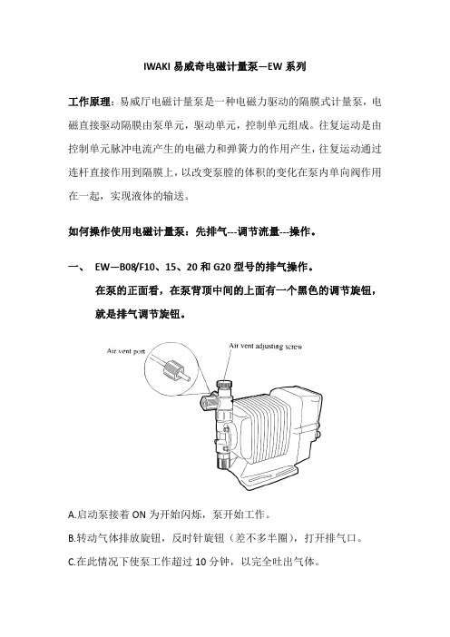
IWAKI易威奇电磁计量泵—EW系列工作原理:易威厅电磁计量泵是一种电磁力驱动的隔膜式计量泵,电磁直接驱动隔膜由泵单元,驱动单元,控制单元组成。
往复运动是由控制单元脉冲电流产生的电磁力和弹簧力的作用产生,往复运动通过连杆直接作用到隔膜上,以改变泵膛的体积的变化在泵内单向阀作用在一起,实现液体的输送。
如何操作使用电磁计量泵:先排气‐‐‐调节流量‐‐‐操作。
一、 EW—B08/F10、15、20和G20型号的排气操作。
在泵的正面看,在泵背顶中间的上面有一个黑色的调节旋钮,就是排气调节旋钮。
A.启动泵接着ON为开始闪烁,泵开始工作。
B.转动气体排放旋钮,反时针旋钮(差不多半圈),打开排气口。
C.在此情况下使泵工作超过10分钟,以完全吐出气体。
D.顺时针旋转排气调节螺母,以关闭排气阀。
E.检查泵的各部分确认无泄漏后,完成排气过程。
二、 流量调整可采用两种方法调节吐出量,即调节冲程频率和调节冲程距离,大多数情况下采用前面种方法调节,在调节冲程频率也不能获得所需的吐出量的情况下,调节冲程距离就是一种辅助方式。
1、吐出量的调节。
根据泵的操作工况和液体的性质确定泵的冲程频率和冲程距离的数值,考虑到泵的性能特性,请按下面的方法确定设置值:a.冲程距离设备为100%,接着调节冲程频率,以获得近似的吐出量。
b.测量吐出量。
c.如果实际所测的吐出量低于所需量,就增加冲程频率,接着,再次测量吐出量。
d.调节冲程距离,此次是为了精确调节吐出量。
f.确认吐出量,并检查吐出量是否精确达到设备值。
2、调节冲程频率。
按“操作”中相关章节调整冲程频率,冲程频率由控制器控制冲程频率的范围为1—180spm.3、冲程长度的调节(从左图泵液屏下那个旋转钮)。
通过改变活塞的往复程度可调节冲程长度。
a.找开供电按钮ON,在泵工作的同时旋转冲程长度—调节旋钮以调节吐出量。
b.从上右图表示了吐出量与冲程长度的关系,吐出量以百分数的形式表示,取铭牌上的最大吐出量为100%。
日本IWAKI计量泵简易操作指南

基本操作:
1、手动操作:(显示为360、其它数值***)
2、自动操作:(显示为EXT、■360、■***;数字前面有■)
进入自动状态→
说明:比如设定信号值上限设定为180,那么在即使EXT信号频率高于180,泵也只能以Spm=180的速度运转。
(出厂设定到360,如出现OVER字样
则在进入自动前没有手动调到360
3、按键锁定:在手动或者EXT秒,解
除锁定。
锁定中泵停止运行,按键失效,解除锁定后方可恢复功能。
4、EXT乘法/除法控制方式选择:
NNN或者/NNN
EXT待机状态(出厂设定为/NNN)5、EXT乘法/除法控制数值设定:
EXT NNN/NNN界面(上面
item4已设定)N值(n=1~999EXT待机状态(出厂设定为/1)
6、自动状态下的显示方式设定:
自动状态下(、■360、■***■
入E-EX界面,E-SP EXT
厂设定为E-SP)
说明:选择E-EX(出厂设定值),EXT运行时屏幕显示“EXT”
选择E-SP,EXT运行时屏幕显示“■Spm”,该数值为泵实际速度,而非信号值。
该显示也可以按以上步骤修改回“EXT”显示。
7、抗干扰设定:
T-5)→按
T10/T50
8、STOP功能之M-OF设定
手动待机状态下→+⊙进入抗干扰界面M-OF界面
(设定为M-OF)
9、STOP功能之
手动待机状态下→M-OF界面
M-ON
“-STOP STOP(如果
)
10、STOP功能之M-ON
“M-ON界
M-OF
态。
此时,M-ON设定解除。
隔膜式电机计量泵 Sigma X 控制型 — Sigma 2 - S2Cb 操作说明书
隔膜式电机计量泵Sigma X 控制型 — Sigma/ 2 - S2Cb操作说明书原版操作说明书 (2006/42/EC)部件编号 982520版本:BA SI 023 01/22 ZH请首先完整阅读使用说明书。
• 请勿丢弃说明书。
因安装或操作失误而造成的损失,由运营商承担。
请阅读下列补充说明!之后您将能更好地使用操作说明书。
文中特别强调:n列举操作指导ð操作指导的结果- 参见(参考)信息说明书中给出了设备正确操作或易于您操作的重要信息。
安全提示安全提示用图标标识 - 参见安全章节。
本操作说明书在印刷时符合当时最新的欧盟规定。
在咨询或订购备件时,请务必指明铭牌上所标识的产品识别码和序列号。
由此可以明确识别设备型号和材料类型。
补充说明插图 1: 请阅读!有效性指明产品识别码和序列号补充说明2目录目录1产品识别码 (6)2安全说明章节 (9)2.1 标识和警告标志 (9)2.2 按规定使用 (9)2.3 人员资格 (9)2.4 可分离保护装置 (11)3储存、运输和拆包 (13)4设备概览和控制元件 (14)4.1 控制元件 (16)4.2 按键功能 (18)5功能说明 (19)5.1 泵 (19)5.2 输送单元 (20)5.3 排气阀和集成式溢流阀 (20)5.4 多层安全膜片 (21)5.5 运行模式 (21)5.6 功能 (22)5.7 选项 (22)5.8 功能和故障指示灯 (23)5.8.1 LCD 屏幕 (23)5.8.2 LED 指示灯 (23)5.9 运行模式、功能和故障状态等级 (24)6装配 (25)6.1 基座 (25)6.2 所需空间 (25)6.3 固定 (26)6.4 装配 HMI 用户控制系统 (26)7安装 (27)7.1 液压安装 (27)7.1.1 溢流阀/减压阀 (29)7.1.2 隔膜破裂传感器 (30)7.1.3 基本安装提示 (30)7.2 电气安装 (31)7.2.1 常规 (31)7.2.2 控制接头 (31)7.2.3 HMI 操作部件 (39)7.2.4 泵,电源 (39)7.2.5 其它组件 (39)8设置的基本信息 (40)8.1 控制系统设置基本信息 (40)8.2 检查可设置的参数 (42)8.3 切换到设置模式 (42)9设置/“菜单” (43)9.1 “信息” (43)9.2 “运行模式” (43)9.3 “设置” (43)9.3.1 “运行模式” (44)9.3.2 “计量” (47)9.3.3 “校准” (48)9.3.4 “输入端/输出端” (49)9.3.5 “系统” (51)9.3.6 “设置系统时间” (52)3目录9.3.7 “日期” (52)9.4 “计时器” (52)9.4.1 计时器“激活” (52)9.4.2 “设置计时器” (52)9.4.3 “全部删除” (54)9.4.4 示例 (55)9.5 “服务” (55)9.5.1 “密码” (55)9.5.2 “清除计数器数据” (55)9.5.3 “日志” (56)9.5.4 “显示屏” (56)9.5.5 “退出 HMI” (56)9.5.6 “隔膜部件编号:XXXXXXX” (56)9.5.7 “备件包部件编号:XXXXXXX” (56)9.6 “语言” (Language) (57)10开始使用 (58)11操作 (61)11.1 手动操作 (61)12维护 (63)12.1 维护安全提示 (63)12.2 标准输送单元: (63)13维修 (65)13.1 安全提示,维修 (65)13.2 清洁阀门 (65)13.3 更换计量隔膜 (67)14排除功能故障 (70)14.1 安全提示,排除功能故障 (70)14.2 无错误信息的故障 (70)14.3 故障信息 (71)14.4 警告信息 (72)14.5 所有其它故障 (72)14.6 日志 (72)14.6.1 日志中的警告信息 (73)14.6.2 日志中的故障信息 (73)14.6.3 日志中的事件 (74)15停用 (75)16技术数据 (77)16.1 性能数据 (77)16.2 黏度 (77)16.3 装运重量 (78)16.4 接触介质的材料 (78)16.5 环境条件 (78)16.5.1 环境温度 (78)16.5.2 介质温度 (78)16.5.3 空气湿度 (79)16.5.4 防护等级和安全要求 (79)16.6 安装高度 (79)16.7 电气连接 (79)16.8 隔膜破裂传感器 (80)16.9 继电器 (80)16.10 齿轮油 (80)16.11 声压级 (81)17尺寸图 (82)18电机数据页 (84)4目录19Sigma/ 2 输送单元 (85)20磨损件 S2Cb (91)20.1 标准 (91)20.2 医药级 (91)21计量流量设置图表 (93)22欧盟认证符合性声明 (94)23Sigma X 控制型操作/设置概览 (95)24Sigma X 控制型总操作菜单 (96)25持续显示界面和辅助显示界面 (100)26索引 (102)5产品识别码1 产品识别码6产品识别码7产品识别码82 安全说明章节2.1 标识和警告标志本操作说明书使用了以下针对不同危险严重程度的信号词:本操作说明书使用了以下不同危险种类的警告标志:2.2 按规定使用n 该泵仅允许用于液体计量介质的计量。
e-HM电泵安装、操作和维护手册说明书
Installation, Operation, andMaintenance ManualModel e-HMTable of Contents Table of Contents1 Introduction and Safety (2)1.1 Introduction (2)1.2 Inexperienced users (2)1.3 Safety terminology and symbols (2)1.4 Warranty (2)1.5 Spare parts (2)1.6 Declaration of Conformity (2)2 Transportation and Storage (2)2.1 Inspect the delivery (2)2.2 Transportation guidelines (3)2.3 Storage guidelines (3)3 Product Description (3)3.1 Pump design (3)3.2 Application limits (3)3.3 The data plate (3)4 Installation (3)4.1 Facility requirements (4)4.1.1 Pump location (4)4.1.2 Piping requirements (4)4.2 Electrical requirements (4)4.3 Install the pump (5)4.3.1 Install the pump on a concrete foundation (5)4.3.2 Electrical installation (5)5 Commissioning, Startup, Operation, and Shutdown (5)5.1 Prime the pump (5)5.2 Check the rotation direction (three-phase motor) (5)5.3 Start the pump (6)6 Maintenance (6)6.1 Service (6)7 Troubleshooting (6)7.1 Troubleshooting table (6)1 Introduction and Safety1.1 IntroductionPurpose of this manualThe purpose of this manual is to provide necessary information for:•Installation •Operation •MaintenanceCAUTION:Read this manual carefully before installing and using the product. Improper use of the product can cause personal in-jury and damage to property, and may void the warranty.NOTICE:Save this manual for future reference, and keep it readily available at the location of the unit.1.2 Inexperienced usersWARNING:This product is intended to be operated by qualified person-nel only.Be aware of the following precautions:•Persons with diminished capacities should not operate the prod-uct unless they are supervised or have been properly trained by a professional.•Children must be supervised to ensure that they do not play on or around the product.1.3 Safety terminology and symbolsHazard levelsHazard categoriesHazard categories can either fall under hazard levels or let specific sym-bols replace the ordinary hazard level symbols.Electrical hazards are indicated by the following specific symbol:Electrical Hazard:Hot surface hazardHot surface hazards are indicated by a specific symbol that replaces the typical hazard level symbols:CAUTION:Description of user and installer symbols1.4 WarrantyFor information about warranty, see the sales contract.1.5 Spare partsWARNING:Only use original spare parts to replace any worn or faulty components. The use of unsuitable spare parts may cause malfunctions, damage, and injuries as well as void the guar-antee.For more information about the product's spare parts, refer to the Sales and Service department.1.6 Declaration of ConformityWe at,Xylem Inc./Goulds Water Technology 1 Goulds Drive Auburn, NY 13021Declare that the following products: NPE, MCS, MCC, 3642/3752,3656, 3656 SP, GB, e-SV, SVI, NPO, Prime Line SP, HB, e-HM, HMS, LC,NPV, LB, LBS comply with Machine Directive 06/42/EC. This equipment is intended to be incorporated with machinery covered by this direc-tive, but must not be put into service until the machinery into which it is to be incorporated has been declared in conformity with the actual provisions of the directive.Nick DaddabboIndustrial Product Engineer2 Transportation and Storage2.1 Inspect the delivery1.Check the outside of the package.2.Notify our distributor within eight days of the delivery date, if the product bears visible signs of damage.3.Remove the staples and open the carton.4.Remove the securing screws or the straps from the wooden base (if any).5.Remove packing materials from the product. Dispose of all pack-ing materials in accordance with local regulations.6.Inspect the product to determine if any parts have been damaged or are missing.7.Contact the seller if anything is out of order.1 Introduction and Safety2.2 Transportation guidelinesPrecautionsWARNING:•Observe accident prevention regulations in force.•Crush hazard. The unit and the components can be heavy. Use proper lifting methods and wear steel-toed shoes at all times.Check the gross weight that is indicated on the package in order to se-lect proper lifting equipment.Position and fasteningThe unit can be transported either horizontally or vertically. Make sure that the unit is securely fastened during transportation, and cannot roll or fall over.2.3 Storage guidelinesStorage locationNOTICE:•Protect the product against humidity, dirt, heat sources, and me-chanical damage.•The product must be stored at an ambient temperature from -40°C to +60°C (-40°F to 140°F).3 Product Description3.1 Pump designThe pump is a multistage, non-self priming pump. The pump can be used to pump:•Cold water •Warm water Intended useThe pump is suitable for:•Civil and industrial water distribution systems•Irrigation (for example, agriculture and sporting facilities)Improper useDANGER:Do not use this pump to handle flammable and/or explosive liquids.WARNING:Improper use of the pump may create dangerous conditions and cause personal injury and damage to property.NOTICE:Do not use this pump to handle liquids containing abrasive, solid, or fibrous substances, toxic or corrosive liquids, potable liquids other than water, or liquids not compatible with the pump construction material.An improper use of the product leads to the loss of the warranty.3.2 Application limitsTable 1: Pressure and temperature limitsSeal Code 1HM, 3HM5HM10HM,15HM,22HM2-6 Stages 7+ Stages 2-5 Stages 6+ Stages All StagesBQE 147PSI at 248F 235PSI at 248F 147PSI at 248F 235PSI at 248F 235PSI at 248F BQV 147PSI at 248F 235PSI at 248F 147PSI at 248F 235PSI at 248F 235PSI at 248F QQE 147PSI at 248F 235PSI at 194F 147PSI at 248F 235PSI at 194F 235PSI at 194F QQV 147PSI at 248F 235PSI at 194F147PSI at 248F235PSI at 194F235PSI at 194FBVE147PSI at 194FNot Avail-able 147PSI at 194F Not Avail-able Not Avail-able3.3 The data plateThe data plate is a label on the pump. The data plate lists key productspecifications.1.Goulds Water Technology Catalog Number2.Capacity range3.TDH range4.Rated speed5.Rated horsepower6.Maximum operating pressure7.Maximum fluid temperature8.Pump serial numberIMQ or other marks (for electric pump only)Unless otherwise specified, for products with a mark of electrical-relat-ed safety approval, the approval refers exclusively to the electrical pump.3 Product Description4 InstallationPrecautionsWARNING:•Observe accident prevention regulations in force.•Use suitable equipment and protection.•Always refer to the local and/or national regulations,legislation, and codes in force regarding the selection of the installation site, plumbing, and power connections.4.1 Facility requirements4.1.1 Pump locationDANGER:Do not use this unit in environments that may contain flam-mable/explosive or chemically aggressive gases or powders.GuidelinesObserve the following guidelines regarding the location of the prod-uct:•Make sure that no obstructions hinder the normal flow of the cool-ing air that is delivered by the motor fan.•Make sure that the installation area is protected from any fluid leaks, or flooding.•If possible, place the pump slightly higher than the floor level.•The ambient temperature must be between -30°C (-22°F) and +40°C (+104°F) unless otherwise specified in the data plate.•The relative humidity of the ambient air must be less than 50% at +40°C (+104°F).Installation above liquid source (suction lift)The theoretical maximum suction height of any pump is 34 ft. In prac-tice, this is not achieved due to the following conditions affecting the suction capability of the pump:•Temperature of the liquid•Elevation above the sea level (in an open system)•System pressure (in a closed system)•Resistance of the pipes•Own intrinsic flow resistance of the pump •Height differences NOTICE:Do not exceed the pumps suction capacity as this could cause cavita-tion and damage the pump.4.1.2 Piping requirementsPrecautionsWARNING:•Use pipes suited to the maximum working pressure of the pump. Failure to do so can cause the system to rup-ture, with the risk of injury.•Make sure that all connections are performed by quali-fied installation technicians and in compliance with the regulations in force.•Do not use the on-off valve on the discharge side in the closed position for more than a few seconds. If the pump must operate with the discharge side closed for more than a few seconds, a bypass circuit must be instal-led to prevent overheating of the water inside the pump.Piping checklist•Pipes and valves must be correctly sized.•Pipe work must not transmit any load or torque to pumpflanges.4.2 Electrical requirements•The local regulations in force overrule these specified require-ments. In the case of fire fighting systems (hydrants and/or sprin-klers), check the local regulations.Electrical connection checklistCheck that the following requirements are met:•The electrical leads are protected from high temperature, vibra-tions, and collisions.•The power supply line is provided with:•A short-circuit protection device •A main disconnect switch.The electrical control panel checklistNOTICE:The control panel must match the ratings of the electric pump. Improp-er combinations could fail to guarantee the protection of the motor.Check that the following requirements are met:•The control panel must protect the motor against overload and short-circuit.•Install the correct overload protection (thermal relay or motor pro-tector).Pump TypeProtectionSingle phase standard electric pump up to 3 HP•Built-in automatic reset thermal-overload protec-tion•Short circuit protection (must be supplied by the installer)Three-phase electric pump•Thermal protection (must be supplied by the instal-ler)•Short circuit protection (must be supplied by the installer)•The control panel must be equipped with a dry-running protec-tion system to which a pressure switch, float switch, sensors, or other suitable device is connected.•The following devices are recommended for use on the suction side of the pump:•When the liquid is pumped from a water system, use a pres-sure switch.•When the liquid is pumped from a storage tank or reservoir,use a float switch or sensors.•When thermal relays are used, relays that are sensitive to phase failure are recommended.The motor checklistUse cable according to rules with 3 leads (2+earth/ground) for single phase versions and with 4 leads (3+earth/ground) for three-phase ver-sion.4 Installation4.3 Install the pump4.3.1 Install the pump on a concrete foundation1.Piping support2.On-off valve3.Flexible pipe or joint4.Check valve5.Control panel6.Do not install elbows close to the pump7.Bypass circuit8.Eccentric reducere wide bends 10.Positive gradient11.Piping with equal or greater diameter than the suction port e foot valve13.Do not exceed maximum height difference 14.Ensure adequate submersion depth1.Anchor the pump onto the concrete or equivalent metal structure.•If the liquid temperature exceeds 50°C, the unit must be anchored only by the motor bracket side and not also by the side of the inlet supporting bracket•If the transmission of vibrations can be disturbing, then pro-vide vibration-damping supports between the pump and the foundation.2.Remove the plugs covering the ports.3.Assemble the pipe to the pump threaded connections.Do not force the piping into place.4.3.2 Electrical installationPrecautionsElectrical Hazard:•Make sure that all connections are performed by quali-fied installation technicians and in compliance with the regulations in force.•Before starting work on the unit, make sure that the unit and the control panel are isolated from the power sup-ply and cannot be energized.Grounding (earthing)Electrical Hazard:•Always connect the external protection conductor to ground (earth) terminal before making other electrical connections.Connect the cable1.Connect and fasten the power cables according to the wiring dia-gram under the terminal box cover.a)Connect the ground (earth) lead.Make sure that the ground (earth) lead is longer than the phase leads.b)Connect the phase leads.NOTICE:Tighten the cable glands carefully to ensure the protection against the cable slipping and humidity entering the terminal box.2.If the motor is not equipped with automatic reset thermal protec-tion, then adjust the overload protection according to the nominal current value of electric pump (data plate).5 Commissioning, Startup,Operation, and ShutdownPrecautionsWARNING:Make sure that the drained liquid does not cause damage or injuries.NOTICE:•Never operate the pump below the minimum rated flow.•Never operate the pump with the delivery ON-OFF valve closed for longer than a few seconds.•Do not expose an idle pump to freezing conditions. Drain all liq-uid that is inside the pump. Failure to do so can cause liquid to freeze and damage the pump.•The sum of the pressure on the suction side (water mains, gravity tank) and the maximum pressure that is delivered by the pump must not exceed the maximum working pressure that is allowed (nominal pressure PN) for the pump.•Do not use the pump if cavitation occurs. Cavitation can damage the internal components.5.1 Prime the pumpH>0H<0+H-H121231.Fill plug2.Drain plug3.FunnelInstallations with liquid level above the pump (suction head)Close the on-off valve located downstream from the pump.Installations with liquid level below the pump (suction lift)Open the on-off valve that is located upstream from the pump and close the on-off valve downstream.5.2 Check the rotation direction (three-phase motor)Follow this procedure before start-up.1.Start the motor.2.Stop the motor.3.If the rotation direction is incorrect, then do as follows:a)Disconnect the power supply.b)In the terminal board of the motor or in the electric controlpanel, exchange the position of two of the three wires of the supply cable.c)Check the direction of rotation again.5 Commissioning, Startup, Operation, and Shutdown5.3 Start the pump1.Start the motor.2.Gradually open the on-off valve on the discharge side of the pump.At the expected operating conditions, the pump must run smoothly and quietly. If not, refer to Troubleshooting (page 6).3.If the pump does not start in correctly in 30 seconds, then do the following:a)Switch off the pump.b)Reprime the pump.c)Start the pump again.4.Switch off and on the pump (for about 30 seconds of continuos running) and make sure that all the trapped air is bled out by re-peating this 2–3 times.NOTICE:Make sure that the pump has bled away all the trapped air. Failure to do so can harm the product.6 MaintenancePrecautionsElectrical Hazard:Disconnect and lock out electrical power before installing orservicing the unit.WARNING:•Maintenance and service must be performed by skilled and qualified personnel only.•Observe accident prevention regulations in force.•Use suitable equipment and protection.6.1 ServiceThe pump does not require any scheduled routine maintenance. If the user wishes to schedule regular maintenance deadlines, they are de-pendent on the type of pumped liquid and on the operating conditions of the pump.Contact the local sales and service representative for any requests or information regarding routine maintenance or service.7 TroubleshootingIntroductionAlways specify the exact pump type and identification code when re-questing information or spare parts from the Sales and Service depart-ment.For other situation not mentioned in the table, refer to the Sales and Service department.7.1 Troubleshooting tableProblem Cause and solutionThe pump does not start.•The thermo-overload protection in the single-phase motor has tripped; it will automatically reset when the motor cools down.•Check the power supply wiring to see that the connections are all tight•Check to see that the circuit breaker or ground-fault protection device has tripped. Or replace any fuses that may have blown.•Check to see if any protection device installed for dry running protection has tripped or hung up.Problem Cause and solutionThe pump starts up but the ther-mal protector is triggered after a short time or the fuses blow.•The power supply cable is damaged, the motor short circuits or thermal protector or fuses are not suited for the motor current. Check and re-place the components as necessary.•The thermo-overload protection (single phase)or of the protection device (three-phase) trips due to excessive current input. Check the pump working conditions.•A phase in the power supply is missing. Check the power supply.•The pump is clogged with solids and the impel-ler becomes bound. Clean the pump.The pump starts but does not de-liver any liquid.•Air is entering the suction piping, check the liq-uid level, the tightness of the suction pipes and the operation of the foot valve.•The pump is not correctly primed. Repeat the instructions in Prime the pump (page 5).The pump’s de-livery is re-duced.•Check for restrictions in the piping system.•Wrong rotation of the impeller (three-phase).Check the direction of rotation.•The pump is not correctly primed. Repeat the instructions in Prime the pump (page 5).6 MaintenanceXylem |’zīləm|1) The tissue in plants that brings water upward from the roots2) A leading global water technology companyWe're 12,000 people unified in a common purpose: creating innovative solutions to meet our world's water needs. Developing new technologies that will improve the way water is used, conserved, and re-used in the future is central to our work. We move, treat, analyze, and return water to the environment, and we help people use water efficiently, in their homes, buildings, factories and farms. In more than 150 countries, we have strong, long-standing relationships with customers who know us for our powerful combination of leading product brands and applications expertise, backed by a legacy of innovation.For more information on how Xylem can help you, go to Xylem Inc.2881 East Bayard Street, Suite A Seneca Falls, NY 13148USATel: (866) 325-4210Fax: (888) 322-5877Visit our Web site for the latest version of this document and more informationThe original instruction is in English. All non-English instructions are translations of the original instruction.© 2013 Xylem IncGoulds is a registered trademark of Goulds Pumps, Inc. and is used under license.。
威卡(WIKA)F2822型拉 压力传感器操作说明说明书
拉/压力传感器(轮辐式),F2822型示例:型号F28222A D P R 1X 914113.01 07/2021 C N威卡(WIKA )操作说明,F2822型© 07/2021 WIKA Alexander Wiegand SE & Co. KG 保留所有权利。
WIKA ®是威卡(WIKA )在各个国家的注册商标。
在开始任何工作之前,请仔细阅读操作说明!请妥善保管以备后用!型号F2822操作说明页码 3 - 203威卡(WIKA )操作说明,F2822型A D P R 1X 914113.01 07/2021 C N目录1. 一般信息 42. 设计与功能 52.1 型号F2822概述 . . . . . . . . . . . . . . . . . . . . .52.2 描述 . . . . . . . . . . . . . . . . . . . . . . . . .52.3 供货范围........................53. 安全 63.1 符号说明........................63.2 预期用途........................63.3 不当使用........................73.4 操作人员责任 . . . . . . . . . . . . . . . . . . . . . .73.5 人员资质........................83.6 个人防护设备 . . . . . . . . . . . . . . . . . . . . . .83.7 标签/安全标识......................94. 运输、包装和储存 104.1 运输 . . . . . . . . . . . . . . . . . . . . . . . . 104.2 包装和储存 . . . . . . . . . . . . . . . . . . . . . . 105. 调试、运行 115.1 调试前注意事项 . . . . . . . . . . . . . . . . . . . . 115.2 安装说明.......................115.3 拉/压力传感器安装 . . . . . . . . . . . . . . . . . . . 125.4 电气连接.......................145.5 连接放大器 . . . . . . . . . . . . . . . . . . . . . . 145.6 引脚分配 型号F2822. . . . . . . . . . . . . . . . . . . 146. 故障 157. 维护和清洁 167.1 维护 . . . . . . . . . . . . . . . . . . . . . . . . 167.2 清洁 . . . . . . . . . . . . . . . . . . . . . . . . 167.3 再校准 . . . . . . . . . . . . . . . . . . . . . . . 168. 拆卸、返修和处置 178.1 拆卸 . . . . . . . . . . . . . . . . . . . . . . . . 178.2 返修 . . . . . . . . . . . . . . . . . . . . . . . . 178.3 处置 . . . . . . . . . . . . . . . . . . . . . . . . 179. 规格 189.1 认证 . . . . . . . . . . . . . . . . . . . . . . . . 1910. 附件 19附件:欧盟符合性声明 204威卡(WIKA )操作说明,F2822型A D P R 1X 914113.01 07/2021 C N1. 一般信息■操作说明中描述的拉/压力传感器均采用先进的技术进行设计和制造。
特芬 Tefen MixRite 水流驱动计量泵 1-60 L h 2-90 L h 操作手册说明书

TRATTAMENTO DELLE ACQUER egolazione della pompaMixRiteIl volume di iniezione viene impostato manualmente ruotando la ghiera nella proporzione desiderata. La quantità di prodotto concentrato iniettato è proporzionale alla quantità di acqua che scorre nella pompaMixRite.Acqua dolceManicottoregolazionedosaggioMotoremiscelatoreTefen dal 1973 è leader nella produzione di miscelatori volumetrici che nonrichiedono energia elettrica per il loro funzionamento e che rispettano l’ambiente.La linea di pompe dosatrici MixRite di Tefen garantisce una precisamiscelazione del prodotto concentrato nella rete idrica o di altri liquidi.È la scelta giusta per molti motivi.Applicazioni■Clorazione■Igienizzazione■Disinfezione dell’acquaLa pompa dosatrice azionata ad acqua MixRite di Tefen è un sistemafacile da usare e ingegnoso che ha dimostrato il suo valore in oltre 90paesi.Tefen è certificata ISO 9001 2015T asso di dosaggioInformazioni su TEFENVantaggi dell’utilizzo di MixRite■Facile installazione■Bassi costi di esercizio e manutenzione■Motore idraulico attivato solo dalla pressione del flusso dell’acqua –non elettrico■Dosaggio proporzionale alla portata■Ripetibilità e omogeneità del dosaggio eccellenti2 | POMPE DOSATRICIClorazione per zone rurali o in casi di emergenza:■Si stima che 2,6 miliardi di persone non abbiano un accesso soddisfacente all’acqua potabile■adatte a condizioni estreme, come la mancanza di elettricità e di vincoli locali■Concentrazione e dosaggio tipici:■Ipoclorito di sodio: 0,3 - 5 PPM■Biossido di cloro: 0,3 – 5 PPM■Perossido di idrogeno: 1 PPM e superiore■Tutti i livelli di concentrazione e dosaggio si riferiscono al contenuto di acqua.Controllo del PH■Per il controllo del pH vi è una vasta gamma di acidi utilizzati, come ad esempio: acido solforico, acido clorico, acido fosforico, acido nitricoIgienizzazione e disinfezioneLe pompe dosatrici proporzionali MixRite sono ampiamente utilizzate per l’igienizzazione e la disinfezione delle reti idriche.Settori che rientrano in questa applicazione:■Trasformazione e igienizzazione dei prodotti agroalimentari■Pulizia delle linee di produzione della birra■Sale operatorie – pulizia e disinfezione delle superfici■Additivi detergenti e igienizzanti da dosare e iniettare, inclusi glutaraldeide e acidi organici come:■acido peracetico, acido formico, ecc.■ammonio quaternario, ecc.ClorazioneProdotti chimici e acidi PVDF34 | POMPE DOSATRICIPompe dosatriciPressione dell’acqua 0,2 – 8 bar Portata 10 – 3.500 L/h Peso 1,8 kg*Attacco3/4”0,03-0,2%, 0,1-0,9%, 0,3-2%, 0,5-5%, 1-10%Pressione dell’acqua 0,2 – 8 bar Portata 7 – 2.500 L/h Peso 1,8 kg Attacco3/4”Portata bassa0,1-0,9%, 0,3-2%, 0,4-4%Pressione dell’acqua 1 – 8 bar Portata 0,05 - 10 m 3/h Peso 7,4 kg Attacco1,5” o 50 mm* Gambe di supporto disponibili su richiesta speciale0,1-1%, 0,2-2%, 1-5%Pressione dell’acqua 1 – 8 bar Portata 0,02 - 5 m 3/h Peso 5 kg Attacco1” o 32 mm* Gambe di supporto disponibili su richiesta speciale0,1-1%, 0,2-2%, 0,5-5%*1-10%: 3 kg5Purificazione dell’acqua potabile6 | POMPE DOSATRICISistema galleggiante percisterne Watch Guard e iniettori ad acqua MixRiteWatch Guard è il primo sistema di diluzione con valvola galleggiante per cisterne progettato per la fornitura di soluzioni diluite in qualsiasi fusto, cisterna o altro tipo di serbatoio. Quando viene collegato ad una fonte idrica standard, Watch Guard si attiva automaticamente e tiene il serbatoio pieno, garantendo una fornitura costante di soluzione diluita per il sistema MixRite.Gli iniettori ad acqua MixRite si collegano in linea alla rete idrica e utilizzano la pressione dell’acqua p e r m i s c e l a r e a c c u r a t a m e n t e l e s o l u z i o n i indipendentemente dalle variazioni di flusso o di pressione.Utilizzando Watch Guard in combinazione con qualsiasi sistema MixRite è possibile ottenere diluzioni elevate, fino a 5 parti per milione.■Consente di ottenere una diluzione elevata in 2 semplici passi■delle sostanze chimiche■Watch Guard è semplice da installare su qualsiasi fusto, cisterna o altro serbatoio■Si attiva automaticamente per mantenere il serbatoio pieno di soluzione miscelata■Punta di misurazione inclusa per le diluzioni da 0,25% a 14,2%■Comprende un dispositivo di ritegno per i divari di azione approvato ASSE 1055B■MixRite si collega in linea alla rete idrica■Fornisce un dosaggio accurato indipendentemente dal flusso d’acqua o dalle variazioni di pressione ■Diversi modelli disponibili per volumi di dosaggio dall’1% al 10% e portate d’acqua da 227 a 25.000 litri all’oraDiluzioni elevateMixRite+=AcquaDiluzione fino a 5 PPMDiluzione 0,25%-14,2%AcquaQualsiasi acido concentrato, cloro o sostanza chimicaDA NON SCALARE(Serbatoio per la soluzione diluita)PUNTA DI MISURAZIONE7Rapporti di induzione per le viscosità mostrateRapporti di diluzione di MixRite in combinazione con l’unità Watch Guard8 | POMPE DOSATRICISistema di bypass proporzionale e automaticoIl sistema TreatRite™ fornisce un metodo proporzionale tra la linea principale (A) e la sotto-linea (B), supportato da un sofisticato sistema idraulico innovativo. La pompa MixRite™ è un’unità volumetrica proporzionale. La combinazione di pompa dosatrice MixRite™ e unità bypass crea un sistema di dosaggio completamente proporzionale. Questo sistema fornisce pertanto all’utente una soluzione perfetta per il trattamento delle acque. L’utente finale del sistema TreatRite™ può dosare i comuni additivi per il trattamento delle acque, come ad esempio: ipoclorito di sodio, biossido di cloro e perossido di idrogeno. Il sistema TreatRite™ può essere utilizzato a diversi intervalli, come riportato qui di seguito:– Linea di trattamento delle acquePerdita di pressione vs. portata5,00,000,400,801,201,6015,025,035,045,055,065,075,085,095,0P e r d i t a d i p r e s s i o n e (b a r )Portata della linea principale (m 3/h)2"3"4"AB90%10%9Gamma :Principio di funzionamento■La valvola di comando pilota rileva il livello dipressione in più punti e controlla la condizione di apertura del diaframma.■Questa operazione regola le portate per generare un rapporto stabile 1:10 tra le linee.Caso di studio (trattamento delle acque)■Portata totale dell’acqua: 67,3 m 3/h ■Tasso di dosaggio desiderato: 0,1%■Quantità dell’additivo: 67,3 x 0,1% = 0,0673 m 3/h Configurazione rilevante: 4’’, 1,5"■Flusso dell’acqua della linea principale: 67,3 x 0,9 = 60,57 m 3/h■Flusso dell'acqua del bypass: 67,3 x 0,1 = 6,73 m 3/h Iniettore rilevante: TF10 0,2%-2%■Impostazione del dosaggio sull’iniettore: 0,0673 / 6,73 = 1%Caratteristiche e vantaggi■Mantiene costante la portata proporzionale ■Idraulico, volumetrico e non elettrico ■Dosaggio proporzionale alla portata■Precisione: qualità in superficie ottimizzata, senza sprechi■Ad ampie portate, la portata tra la linea principale e la linea secondaria rimane 10:1 ■Pressione operativa fino a 8 bar ■Elevata resistenza ai raggi UV ■Elevata resistenza chimica■Sistema preimpostato. Nessuna calibrazione necessaria■Ripetibilità e omogeneità del dosaggio eccellenti■Di facile installazione, utilizzo e manutenzione, senza rischi elettriciTF-52.53.5TF-10Trattamento delle acqueCon trattamento delle acque si intende qualsiasiprocesso volto a migliorare la qualità dell’acqua perrenderla più idonea a uno specifico uso finale. L’usofinale può essere: produzione di acqua potabile,fornitura di acqua a uso industriale, irrigazione,manutenzione dei flussi fluviali, ricreazione delle acquee molti altri usi, compresa la reimmissione sicuranell’ambiente.Tefen Flow Products è uno dei principali fornitori diprodotti per tubazioni industriali a livello mondialeper soddisfare le esigenze di impianti idrici e didepurazione. Il sistema di Tefen, superiore allaconcorrenza, è composto da raccordi, valvole e tubie garantisce prestazioni uniformi in tutti gli impianti ditrattamento Le proprietà non corrosive garantisconobuone prestazioni sul lungo periodo e bassi costi dimanutenzioneI prodotti Tefen Flow sono certificati NSF e hannoconseguito l’approvazione WRAS.10 | POMPE DOSATRICI11RACCORDI IN PVDFPRE-FILTRO DELL’ACQUAVALVOLETEFEN LTD.KibbutzNahsholim3081500Israele|Tel.97246395944|Fax.97246390813|********************| E D I T I O N 0 4 I T 0 4 / 2 0 2 0 n o w -b r a n d i n g . c o . i le/o le specifiche tecniche dei prodotti e/o aggiungere e/o rimuovere prodotti e/o modificare i prezzi e/o i termini e le condizioni specificati nel presente documento in qualsiasi momento e a sua esclusiva discrezione, senza alcun preavviso.。
计量泵十大品牌合集计量泵品牌哪个比较好

计量泵十大品牌合集中国计量泵公司排名1.上海沈泉泵阀制造有限公司上海沈泉泵阀制造有限公司是一家专业生产,销售管道泵,排污泵,消防泵,化工泵等给排水设备的厂家,产品涉及工矿企业、农业、城市供水、石油化工、电站、船舶、冶金、高层建筑、消防供水、工业水处理和纯净水、食品、制药、锅炉、空调循环系统等行业领域。
2. 新疆百利万通机电设备有限公司新疆百利万通机电设备有限公司成立于2018年,位于乌鲁木齐市星河水泵市场及恒汇机电城主要经营:水泵,滴灌泵,管道泵,多级泵,渣浆泵,压滤机入料泵,双吸泵,离心泵,潜水泵,深井泵,污水泵,化工泵,无塔供水设备吗,广泛应用于生活给水,农用排灌、化工、制药、造纸、石油、采矿、建筑、冶金、消防等各行各业。
3. 湖南中开泵业有限公司湖南中开泵业有限公司(中开泵业、中泵、长泵特泵、汨罗制泵)是长沙水泵行业知名水泵制造厂家,注册商标“长一制泵”,长沙水泵厂始建于1951年,曾用名称长沙通大集团长沙水泵厂,长沙工业泵总厂,长沙天鹅工业泵厂,于1951年正式建厂,多年来一直从是国内知名的专业中开泵-多级泵-双吸泵-立式斜流泵-冷凝泵-凝结水泵-立式长轴泵-清水泵-船用挖砂泵等泵类设计、研发和生产的综合泵业公司。
4. 四川三台力达泵业有限公司四川三台力达泵业有限公司,成立于1995年,现座落于三台县青东坝工业集中区四号路;注册资本2000万元,拥有资产1.2亿余元,员工130余人,其中中高级专业技术管理人员40余人。
公司厂区占地面积80余亩,包括办公大楼、生产车间、职工宿舍、活动中心等建筑。
具有模具制造、铸锻件生产、理化检验、机械加工、装配、测试的完整泵制造体系。
有各类主要设备200余台(套),其中包括大型立车、铣床、龙门刨、抛丸机、新型造型机、1.5吨中频炉、600吨液压机、自动测试台架、大型清洗机等在内的重点设备达30余台(套)。
年生产能力20000余台,大口径可达1m,能生产制造灰铸铁、球墨铸铁、不锈钢、高分子材料等众多材质的产品。
易维奇EHN系列计量泵中文说明书

感谢选用EHN型电磁计量泵。
本使用手册由“安全部分”、“概述部分”、“安装部分”、“操作部分”和“维护部分”组成,介绍了本产品的正确安装、操作、维护和故障检修的步骤。
请认真阅读本手册的全部内容,确保本计量泵的最佳性能、使用安全和维修。
目录安全指引............................................................................................................ 1~3 产品概述 1.开箱检查 (4)2.工作原理 (4)3.型号识别 (5)4.规格 (6)5.操作功能 (7)6.STOP功能 (8)7.概述.............................................................................….. 8,9 安装 1.安装前 (10)2.搬运注意事项...........................................................… 10,11 3.安装 (12)4.设管.........................................................................….. 13,14 5.布线..........................................................................… 14~18 操作 1.操作..........................................................................… 19~23 2.控制器的操作............................................................. 24~35 维护安全指引 (36)1.故障检修 (36)2.维护与检查 (37)3.易损件 (37)4.拆卸与组装................................................................... 38~42 部件分解图......................................................................…………………. 43~46 外形尺寸......................................................................……………………. 47~50 安全指引为了正确、安全使用本计量泵●“安全指引”部分介绍了操作本产品时需要注意的一些重要细节。
电磁计量泵说明书
EM00136176
Rev 1.4
9
图一
EM00136176
Rev 1.4
10
必须成套使用我公司提供的连接软管、底阀及注射阀,这些都是准确加药的必要 条件;底阀过滤器必须安装在距离容器底部 5-10 厘米的位置以上,以免被沉淀 物堵塞而损坏泵的液压部位。 如果条件具备,最好在出水端配置安全阀,以免出现堵塞时损坏泵; 拧紧连管螺母时请用手拧紧即可,不能使用工具; 进出口软管的连接:把软管插到软管管嘴的根部并套好卡环,以防止滴液、漏气 引起空转和腐蚀。请定期检查管道情况,如果软管接口老化,请速更换软管或者 裁掉老化部分并重新接紧。 手动排气:排气阀在计量泵的右面,将其拧松后,计量泵在工作状态下排除气体 后拧紧即可。注意排气出口也必须接软管以便把气液混合物排走,防止滴到泵头 腐蚀螺栓。 将泵冲程调节旋钮调节到 100%位置,对泵进行排气; 出口管路压力一定要高于进口管路压力,否则会产生虹吸; 对泵进行流量标定:实际使用中由于条件的改变,实际流量和铭牌流量不一致是 正常的。如果现场要求比较高,可在入口处通过加药罐单位时间的减少量进行标 定,并记录标定结果,在正式运行时以标定的结果来对计量泵进行百分比设定。 泵工作 800 小时后,要使用工具再次拧紧泵头上的四条固定螺栓。
F
3
正极
抗:200 OHM)
4
无用
F 保险丝:2A 250V T 5x20
投药模式选择设置
投药模式选择开关(如图所示)
可选两种不同的模式:
1.恒定流量模式 (将模式开关调至 C 位置) 泵根据选择的频率百分比来投药。
2.流量比例调节模式(将模式开关调至 P 位置) 根据接收到的 4-20 毫安范围内的电流信号, 泵按比例投药。
SI-EH
压力(%)
100 90 90 80 80 70 70 60 60 50 50 40 40 30 30 20 20 10 10 00 0 0.5 1.5 1 2 2.5 3.5 3 4
位置 压力
100 90 90 80 80 70 70 60 60 50 50 40 40 30 30 20 20 10 10 0 0 0.5 1.5 1 2 2.5
SI/EH PRO-改进的监测和控制:
• 数据记录仪-记录事件、分析和报警信息。
• Rotork 蓝牙设定器 PRO-在 SI/EH 执行机构和 Insight2 软件 之间进行数据下载和上传。
• 半自动极限位置校准。
• 部分行程—可远程或使用 Rotork 蓝牙®设置器 Pro 就地激 活。
• 可选 ESD 手动复位—限制执行器的操作,直到当过程控制 安全时在本地手动复位。
SI-EH 直行程性能数据
EH-L 执行器可灵活用于各种特殊作业,且设计可用于双位置或 紧急关闭。执行器在慢速模式选项下也可设置用于精度<0.5%的 模拟控制。当电源断开或收到控制信号时可令弹簧伸缩或双动以 进行故障保护或末位锁定。可选蓄能器和各种液压泵的尺寸均能 满足所需的操作速度和故障安全操作。
• 兼容 Rotork Insight2 软件。
•
兼容各种
Rotork
网
络
通
讯
卡
-Pakscan
,
®
Profibus
、
Foundation Fieldbus®、Devicenet® 和 Modbus。
Insight2
重新定义流体控制
3
SI-EH 角行程执行器
Skilmatic SI/EH-Q 系列产品为角行程阀门和调节 器提供了独一无二且安全可靠的电动故障安全型 和调节控制的解决方案。
企业信用报告_易威奇泵业贸易(深圳)有限公司
基础版企业信用报告
5.10 司法拍卖 ....................................................................................................................................................9 5.11 股权冻结..................................................................................................................................................10 5.12 清算信息..................................................................................................................................................10 5.13 公示催告..................................................................................................................................................10 六、知识产权 .......................................................................................................................................................10 6.1 商标信息 ....................................................................................................................................................10 6.2 专利信息 ....................................................................................................................................................10 6.3 软件著作权................................................................................................................................................10 6.4 作品著作权................................................................................................................................................10 6.5 网站备案 ....................................................................................................................................................11 七、企业发展 .......................................................................................................................................................11 7.1 融资信息 ....................................................................................................................................................11 7.2 核心成员 ....................................................................................................................................................11 7.3 竞品信息 ....................................................................................................................................................11 7.4 企业品牌项目............................................................................................................................................11 八、经营状况 .......................................................................................................................................................12 8.1 招投标 ........................................................................................................................................................12 8.2 税务评级 ....................................................................................................................................................12 8.3 资质证书 ....................................................................................................................................................12 8.4 抽查检查 ....................................................................................................................................................12 8.5 进出口信用................................................................................................................................................12 8.6 行政许可 .............................................................................................................பைடு நூலகம்......................................12
易威奇计量泵

磁力泵一、启动前的准备和检查1、检查泵的有关配管联接就绪,泵体附件完好,电气仪表符合要求。
2、检查泵油箱装填符合标准的润滑油,润滑油无变质,并到指定油位。
3、有联轴器的泵需手动盘车、检查各转动部分是否灵活,有无不正常的卡死,杂音情况,无阻力感和磨擦感。
4、打开泵入口阀及泵出口线上排气阀,进行排气,使泵内充满液体,然后关闭排气阀。
排气时,也可轻轻地转动轴,使泵内气体完全排出。
5、点试泵,确认泵的旋转方向是否正确,轴承和泵体无异常振动和噪音,压力正常,如一切正常,泵停止转动5分钟后可启动泵。
二、磁力泵的启动:1、全闭排出阀。
2、接通电源,待泵运转到额定转速。
3、如果需要,再次打开排气阀进行排气,直到彻底无气后,再关闭排气阀。
4、注意电流,缓慢打开出口阀,注意不要超负荷。
使压力、流量达到额定数值。
5、检查泵的轴承、油位、工作状态、机体振动、噪音、泄漏、温度等状况有无异常。
三、停泵1、逐渐关闭出口阀。
2、切断电源。
3、关闭入口阀。
4、盘车,检查泵转动的灵活性。
5、将泵内介质放出四、磁力泵的切换注意:原则上切换时应保持系统流量、压力保持不变,严禁抽空、抢量等现象发生。
1、备用泵应做好一切启动准备工作。
2、打开备用泵入口阀,并排气。
3、启动备用泵至额定转速,检查振动、泄漏、温度等,然后注意电流变化,逐渐打开备用泵出口阀,同时在保持流量、压力不变的情况下,逐渐关闭被切换泵的出口阀。
当备用泵达到额定压力和流量时,关闭被切换泵的排出阀并切断电源,对其做停泵后的处理。
五、磁力泵操作注意事项:1、磁力泵在任何情况下,不允许在无润滑措施下运行,以免损坏机件。
2、不允许在入口阀不开的情况下启动泵,做断流运转。
3、不允许停泵后,不关闭出口阀门。
4、只允许用出口阀调节流量、压力,不可用入口阀调节。
六、泵正常运转时检查要点。
1、检查泵出口压力、出口流量是否满足工艺要求。
2、轴承箱温度是否过高,轴承箱温度不能高于70℃或环境温度+40℃。
易威奇泵业国际贸易(上海)有限公司介绍企业发展分析报告
Enterprise Development专业品质权威Analysis Report企业发展分析报告易威奇泵业国际贸易(上海)有限公司免责声明:本报告通过对该企业公开数据进行分析生成,并不完全代表我方对该企业的意见,如有错误请及时联系;本报告出于对企业发展研究目的产生,仅供参考,在任何情况下,使用本报告所引起的一切后果,我方不承担任何责任:本报告不得用于一切商业用途,如需引用或合作,请与我方联系:易威奇泵业国际贸易(上海)有限公司1企业发展分析结果1.1 企业发展指数得分企业发展指数得分易威奇泵业国际贸易(上海)有限公司综合得分说明:企业发展指数根据企业规模、企业创新、企业风险、企业活力四个维度对企业发展情况进行评价。
该企业的综合评价得分需要您得到该公司授权后,我们将协助您分析给出。
1.2 企业画像类别内容行业仓储业-其他仓储业资质增值税一般纳税人产品服务际贸易、转口贸易;化工泵及其零部件和配套1.3 发展历程2工商2.1工商信息2.2工商变更2.3股东结构2.4主要人员2.5分支机构2.6对外投资2.7企业年报2.8股权出质2.9动产抵押2.10司法协助2.11清算2.12注销3投融资3.1融资历史3.2投资事件3.3核心团队3.4企业业务4企业信用4.1企业信用4.2行政许可-工商局4.3行政处罚-信用中国4.4行政处罚-工商局4.5税务评级4.6税务处罚4.7经营异常4.8经营异常-工商局4.9采购不良行为4.10产品抽查4.11产品抽查-工商局4.12欠税公告4.13环保处罚4.14被执行人5司法文书5.1法律诉讼(当事人)5.2法律诉讼(相关人)5.3开庭公告5.4被执行人5.5法院公告5.6破产暂无破产数据6企业资质6.1资质许可6.2人员资质6.3产品许可6.4特殊许可7知识产权7.1商标7.2专利7.3软件著作权7.4作品著作权7.5网站备案7.6应用APP7.7微信公众号8招标中标8.1政府招标8.2政府中标8.3央企招标8.4央企中标9标准9.1国家标准9.2行业标准9.3团体标准9.4地方标准10成果奖励10.1国家奖励10.2省部奖励10.3社会奖励10.4科技成果11土地11.1大块土地出让11.2出让公告11.3土地抵押11.4地块公示11.5大企业购地11.6土地出租11.7土地结果11.8土地转让12基金12.1国家自然基金12.2国家自然基金成果12.3国家社科基金13招聘13.1招聘信息感谢阅读:感谢您耐心地阅读这份企业调查分析报告。
- 1、下载文档前请自行甄别文档内容的完整性,平台不提供额外的编辑、内容补充、找答案等附加服务。
- 2、"仅部分预览"的文档,不可在线预览部分如存在完整性等问题,可反馈申请退款(可完整预览的文档不适用该条件!)。
- 3、如文档侵犯您的权益,请联系客服反馈,我们会尽快为您处理(人工客服工作时间:9:00-18:30)。
型号识别
(VC/VH)
EHN - B 11 VC 1 R - NAE
驱动单元代码 (平均功耗) B:20W C:24W
膜片有效直径 11:10mm 16:15mm 21:20mm 过流端材质代码 31:30mm VC, VH 36:35mm
软管连接直径 (mm) 1: Ø4 × Ø9 *2:Ø4 × Ø6 *3:Ø6 × Ø8 4:Ø8 × Ø13 *5:Ø9 × Ø12 PVC 软管(标准规格) * 聚四氟乙烯或聚乙烯软管(特殊规格)
规格
型号
EHN-B11-NAE EHN-B16-NAE EHN-C21-NAE
最大吐出量
mL/min
30
55
110
每冲程吐出量 mL/shot 0.04 - 0.08 0.08 - 0.15 0.12 - 0.31
最大吐出压力
MPa 1.0
0.7
冲程长度调节范围
%
50 - 100
40 - 100
冲程频率
脉冲分配(n :1)
泵通过外部信号进行除法法则运 行。 对 应“n”个脉冲信号的输入, 泵进行 1 次注射。“n”可以设置为 1 ~ 999。
注 :当泵收到外部接点(STOP)信号时,也 可对泵进行操作(通过按键转换)。在这 种情况下,当泵在 EXT 模式下运行,并 收 到 STOP 信 号 时, 泵 将 与 EXT 信 号 同步运行。
VC/VH 型
FC 型
SH 型
宽电压电源
所有型号均采用 AC100 ~ 240V 宽 电压规格,从而免除由于电源电压 差异而带来的困扰。
精确调节
采 用 数 字 化 控 制 器, 可 在 1spm ~ 360 spm 范围内调节冲程频率,结合 冲程长度的调节 , 可以实现从最小 流量到最大流量之间的精确调节。
排气阀
小流量型(EHN-11,16 和 21)配 置有排气阀,通过转动排气旋钮便 可轻易地把泵腔内的空气排出。
防水 / 防尘设计
泵的各部分如驱动单元和控制单元 均采用防水 / 防尘设计,其防护等 级相当于 IP66。
注 :泵不可安装于户外。
3
控制器与泵头的不同组合 可以应对广泛应用需求
标准型 EHN-R 系列
铝陶瓷
哈氏合金 C276
FKMΒιβλιοθήκη EPDMPCTFE
SUS316
PVC
PVC
PVDF
SUS316
PTFE
FKM
EPDM
–
–
PTFE + EPDM(EPDM 不与液体接触)
PVC: 透明聚氯乙烯 FKM: 氟橡胶 EPDM : 三元乙丙橡胶
PCTFE: 聚氯三氟乙烯 PTFE : 聚四氟乙烯 PVDF: 聚偏二氟乙烯
泵类型 FC 2:Ø4 × Ø6 6:Ø10 × Ø12 SH 9:Rc 1/4
控制器 R:标准型 Y:数字/模拟转换型
8
EHN
系列
泵的规格
(VC/VH)
型号 最大吐出量 每冲程吐出量 最大吐出压力 冲程频率 冲程长度 接头(软管直径) 电源 排气阀 选购件
mL/min mL/shot
MPa spm
EHN-Y
主流管 (纯净水)
脉冲流量计
脉冲信号
CT-U 储罐 杀菌剂
止回阀
静态混合器 喷嘴
EHN-R, EHN-Y 7
技术参数
垫片 阀球 O 型圈 泵头 膜片 阀套
阀座
结构与材质
材质代号 泵头 阀球 阀座 阀套 垫片 O 型圈 膜片
VC
VH
FC
SH
PVC
PVC
PVDF
SUS316
铝陶瓷
哈氏合金 C276
低的压力下运行,吐出量将会大于上述数据,当吐出压力低于或等于 0.12MPa,请务必使用止回阀以防过量供给。
6
EHN
系列
EHN 系列广泛应用于水处理
现场中添加各种化学药液
往锅炉中注入锅炉药剂
由于泵可在小流量下精确运行,因此可 以注入未经稀释的纯净的锅炉药剂。
CT-U25N/50NR
储罐
A 注射至供水泵的吐出端
* 关于 IMP 系列的详细情况请参考相关样本说明书。
纯水洗涤槽 洗涤槽
EHN-R 电镀液槽 CT-U 储罐
* 关于 TC-300 的详细情况请参考相关样本说明书。
蒸馏水杀菌
(按比例混合纯净水和杀菌剂)
EHN-R
泵通过脉冲流量计的信号,根据纯净水的流量按比例注入杀菌剂,因此无论纯净水流量如何变化,均可始终保持同一混合浓度。
多种泵头
多 种 类 型 的 标 准 泵 头(VC/VH), 自动排气型(NAE)和高压缩比型 (55 型)
注 :NAE 和 55 型的详细资料请见第 5 页。
冲程长度调节旋钮
控制面板
2
EHN
系列
控制单元
多功能 EHN-Y 型拥有数字输入以 及模拟信号输入,与 EHN-R 型一 起被列入标准产品系列。
脉冲分配(n :1) 泵通过外部信号进行除法法则运行。 对应“n”个脉冲信号的输入,泵进 行 1 次注射。“n”可以设置为 1 ~ 999。
注 :如果“n”设为 1,泵会进行同步运行, 如果 EHN 与选配的 EH 控制器一起使 用时,请采用此功能。
90
P1
0
4
8
mA
16 20
5
可专用于输送特殊化学药液
阀球
O 型圈 膜片 泵头 垫片
阀套 阀座
过流端材质
材质代号 泵头 阀球 阀座 阀套 垫片 O 型圈 膜片
VC PVC 铝陶瓷 FKM PVC PTFE FKM PTFE + EPDM(EPDM不与液体接触)
规格
型号
最大吐出量
mL/min
每冲程吐出量
mL/shot
最大吐出压力
MPa
冲程长度调节范围
%
冲程频率
过流端材质
吸入口
泵 的 气 锁 状 态 一 旦 解 除,便 回 复 到 正 常 运 行 状 态 吐 出 液 体。 同时也会有少量液体从自动排 气阀流出。
材质代号 泵头 接头 分离杆 阀球 阀座 O 型圈
VC
钛 铝陶瓷 FKM FKM
VH PVC PVC
哈氏合金 C276 哈氏合金 C276
EPDM EPDM
spm
1 - 360
接头(软管直径)
Ø4 × Ø9
电源
AC100 - 240V 50/60Hz 单相
附件
止回阀 CA-1, PVC 软管 3 米
工作条件 : 泵输送液体温度:0 ℃- 40 ℃ 环境温度:0 ℃- 40 ℃ 注:最大吐出量是指在最大吐出压力和常温下泵输送清水时的数值,如果在较
低的压力下运行,吐出量将会大于上述数据,当吐出压力低于或等于 0.12MPa,请务必使用止回阀以防过量供给。
工作原理(NAE型)
构造(55型)
手动排气口
手动排气调节螺母
空气
自动排气阀
分离杆
接头
阀球 阀座
泵头
O 型圈
来自吸入口的气体通过泵头到 达接头处,因泵的吐出端受压, 而排气阀端压力低于泵吐出端 压 力,所 以 气 体 会 经 过 自 动 排 气 阀 并 打 开 阀 门,与 液 体 一 起 一点一点往外排放。
除手动和 EXT(脉冲乘积 / 脉冲分 配)操作外,亦可利用模拟信号进 行操作。 还可通过外部接点信号,实现泵的 STOP 功能。标准型内置有 DC/12V 的传感器电源。
控制器功能
手动操作
可通过按键控制泵的运行 / 停止 及设置冲程频率,其范围为 1spm ~ 360 spm。无论泵正在运行或处于停 止状态,均可对冲程频率进行设置。
控制器 R:标准型 Y:数字/模拟转换型
特殊配置 NAE:自动排气型 55:高压缩比型
(FC/SH)
EHN - B 11 FC 2 R
驱动单元代码
(平均功耗) B:20W C:24W
膜片有效直径
11:10mm
21:20mm 31:30mm 36:35mm
过流端材质代码 FC, SH
软管连接直径 (mm)
EXT 运行
脉冲乘积(1 :n)
泵通过外部脉冲信号进行乘积法则 运行。对应 1 个脉冲信号,泵进行 n 次注射。“n”可以设置为 1 ~ 999 。进行乘积运行期间输入的脉冲信 号将被储存,最多可储存 255 个脉 冲信号。
示例(1 : 3)
输入脉冲
储存信号
STOP 功能
当泵收到外部接点信号时,泵将 会停止运行,直到这一外部接点 (STOP)信号被解除为止。利用这 种功能,可以进行 ON/OFF 控制, 同时也便于与液位传感器配套使用。
示例( 3 : 1)
EHN-R
输入脉冲
液位传感器
泵运行 运行 停止
化学药液储罐
泵运行 运行 停止
4
注 :如果“n”设为 1,泵会进行同步运行, 如果 EHN 与选配的 EH 控制器一起使 用时,请采用此功能。
注入点
主管道 液位传感器监视储罐内的液位, 当液位低于下限时使泵停止。
EHN
系列
数字 / 模拟转换 EHN-Y 型
易威奇
EHN
系列
电磁计量泵
最新型数字式控制和宽电压规格的电磁计量泵
EHN 系列配置技术成熟的 EH-R 系列泵头, 驱动装置以及最新开发的控制单元, 是最新型电磁隔膜式计量泵。
最新型电磁计量泵 数字式控制和宽电压
EHN 系列是最新型电磁隔膜式计量泵,配置技术成熟 的 EH-R 系列泵头,驱动装置以及最新开发的控制单 元。100V ~ 240V 的宽电压及数字化控制的 EHN 系列 可方便应用于各种化学药液的添加工序。
