930984-戴利科技设备服务清单
网络安全等级保护备案表
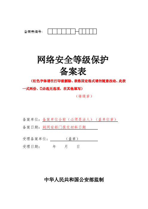
网络安全等级保护备案表(红色字体请在打印前删除、表格固定格式请勿随意改动、此表一式两份、 必选无选项,在其他填写)(骑缝章)备案单位:备案单位全称(必须是法人)(盖单位章) 备案日期:到网安部门提交材料日期受理备案单位: (盖章) 受理日期: 年 月 日中华人民共和国公安部监制备案表编号:填表说明一、制表依据。
根据《信息安全等级保护管理办法》(公通字[2007]43号)之规定,制作本表;二、填表范围。
本表由第二级以上网络运营者或其主管部门(以下简称“备案单位”)填写;本表由四张表单构成,表一为单位信息,每个填表单位填写一张;表二为网络基本信息,表三为网络定级信息,表二、表三每个网络填写一张;表四为第三级以上网络需要同时提交的内容,由每个第三级以上网络填写一张,并在完成系统建设、整改、测评等工作,投入运行后十个工作日内向受理备案公安机关提交;表二、表三、表四可以复印使用;三、保存方式。
本表一式二份,一份由备案单位保存,一份由受理备案公安机关存档;四、本表中有选择的地方请在选项左侧“ ”划“√”,如选择“其他”,请在其后的横线中注明详细内容;五、封面中备案表编号(由受理备案的公安机关填写并校验):分两部分共11位,第一部分6位,为受理备案公安机关代码前六位(可参照行标GA380-2002)。
第二部分5位,为受理备案的公安机关给出的备案单位的顺序编号;六、封面中备案单位:是指负责备案单位的法人单位全称;七、封面中受理备案单位:是指受理备案的公安机关网络安全保卫部门名称。
此项由受理备案的公安机关负责填写并盖章;八、表一05单位负责人:是指主管本单位网络安全工作的领导;九、表一06网络安全/等级保护责任部门:是指单位内负责网络安全工作的部门;十、表一08隶属关系:是指网络运营者与上级行政机构的从属关系,须按照单位隶属关系代码(GB/T12404―1997)填写;十一、表二02网络编号:是由备案单位给出的本单位备案网络的编号;十二、表二12网络平台:是指网络所处的网络环境和网络构架情况;十三、表二14关键产品使用情况:国产品是指网络中该类产品的研制、生产单位是由中国公民、法人投资或者国家投资或者控股,在中华人民共和国境内具有独立的法人资格,产品的核心技术、关键部件具有我国自主知识产权;十四、表二15网络采用服务情况:国内服务商是指服务机构在中华人民共和国境内注册成立(港澳台地区除外),由中国公民、法人或国家投资的企事业单位;十五、表三01、02、03项:填写上述三项内容,确定网络安全保护等级时可参考《网络安全等级保护定级指南》,网络安全保护等级由业务信息安全等级和系统服务安全等级较高者决定。
930产品说明书新

9.3油泵电机电缆W3(采煤机自带)
型号UCPQ—G
电压等级3300V
连续载流量30A
芯线标称3x10+1x10+3x6
电缆外径φ38mm
9.4牵引电机电缆W4,W5(采煤机自带)
型号UCPQ—G(带屏蔽)
电压等级1000V
连续载流量138A
芯线标称3x35+1x16+4x4
电缆外径φ45.26mm
1.1高压箱结构
高压箱分为两个腔体,从采空侧看,箱体左侧连线的是接线腔,右侧是隔爆腔。它们之间由3300V单芯过墙电缆及多芯过线组来联系。
在接线腔中用于进出线的喇叭口共十个。采空侧两个大喇叭口,引入1W电缆,另一备用。,出线的四个大喇叭口和四个小喇叭口在煤壁侧,分别引出W1,W2,W3,W6,W7电缆。接线腔上部开盖,腔内设有一个接线端子排用于控制和监测电缆的接线;腔内底部有一接地螺栓,用于进出线电缆的接地连接。
SB4是采煤机先导试验按钮,SB5是采煤机对运输机闭锁按钮。
图1.3
3.采煤机监测系统和控制系统原理及保护功能
3.1采煤机监测系统原理如图1.4所示,监测中心采用工业控制机。
采煤机监测中心,利用微电脑技术及专家系统,把实时数据库理论和相关的现代控制方法融合在一起。通过接口电路板采煤机送来的信号状态、数据、进行处理和分析,完成采煤机恒功率控制和故障诊断等功能;并对采煤机运行状态进行记录,预报警及相应的紧急故障处理,故障状态下的事故分析,操作指导及提示等功能。
第一章
930电牵引采煤机整机供电电压为3300V,装机总功率930KW,截割电机最大功率400KW。其机型为:MGTY400/930-3.3D。
第一节概述
NI sbRIO-9607单板RIO OEM设备使用开始指南说明书

GETTING STARTED GUIDENI sbRIO-9607Single-Board RIO OEM DevicesThis document describes how to begin using the NI sbRIO-9607.Safety GuidelinesOperate the sbRIO-9607 only as described in the user documentation.Caution The sbRIO-9607 must be installed in a suitable enclosure prior to use.Caution NI makes no product safety, electromagnetic compatibility (EMC), or CEmarking compliance claims for the sbRIO-9607. The end-product supplier isresponsible for conformity to any and all compliance requirements.Caution Exercise caution when designing an enclosure for the sbRIO-9607.Auxiliary cooling may be necessary to keep the sbRIO-9607 within the specifiedoperating temperature range. Refer to the NI sbRIO-9607 Specifications on /manuals for more information about the maximum operating temperature rating. Forinformation and examples regarding factors that can affect thermal performance,visit /info and enter the Info Code sbriocooling.Caution Do not operate the sbRIO-9607 in a manner not specified in thisdocument. Product misuse can result in a hazard. You can compromise the safetyprotection built into the product if the product is damaged in any way. If the productis damaged, return it to NI for repair.Safety VoltagesConnect only voltages that are below these limits.V terminal to C terminal30 VDC maximum, Measurement Category I Measurement Category I is for measurements performed on circuits not directly connected to the electrical distribution system referred to as MAINS voltage. MAINS is a hazardous live electrical supply system that powers equipment. This category is for measurements of voltages from specially protected secondary circuits. Such voltage measurements include signal levels, special equipment, limited-energy parts of equipment, circuits powered by regulated low-voltage sources, and electronics.Caution Do not connect the sbRIO-9607 to signals or use for measurements withinMeasurement Categories II, III, or IV.Preparing the EnvironmentEnsure that the environment in which you are using the sbRIO-9607 meets the following specifications.-40 °C to 85 °CLocal ambient operating temperature neardevice (IEC 60068-2-1, IEC 60068-2-2)Maximum reported onboard sensor temperatureCPU/FPGA temperature98 °CPrimary System temperature85 °CSecondary System temperature85 °CNote Ensure that the local ambient, reported CPU/FPGA, and reported PrimarySystem temperatures do not exceed any of the maximum temperatures listed in thisdocument. For more information about how to access the onboard sensors, visit/info and enter the Info Code sbriosensors.Operating humidity (IEC 60068-2-78)10% RH to 90% RH, noncondensing Pollution Degree (IEC 60664)2Maximum altitude5,000 mIndoor use only.Note Refer to the device specifications on /manuals for completespecifications.2| | NI sbRIO-9607 Getting Started GuideUnpacking the KitCaution To prevent electrostatic discharge (ESD) from damaging the device,ground yourself using a grounding strap or by holding a grounded object, such as your computer chassis.1.Touch the antistatic package to a metal part of the computer chassis.2.Remove the device from the package and inspect the device for loose components or anyother sign of damage.CautionNever touch the exposed pins of connectors.Note Do not install a device if it appears damaged in any way.3.Unpack any other items and documentation from the kit.Store the device in the antistatic package when the device is not in use.Verifying the Kit ContentsVerify that the following items are included in the sbRIO-9607 kit.Figure 1.sbRIO-9607 Kit Contents1.sbRIO Device2.NI CompactRIO Device Drivers Media3.Getting Started Guide4.Power Supply5.10-pin IDC to 9-pin DSUB Cable6.Power Cable Assembly7.Standoffs and Screws8.NI 9694 Digital I/O Breakout RMC BoardNote The provided power supply is only intended for the getting startedexperience. NI recommends the use of a power supply that meets the specifications listed in the NI sbRIO-9607 Specifications for system deployment.NI sbRIO-9607 Getting Started Guide | © National Instruments | 3Installing Software on the Host ComputerBefore using the sbRIO-9607, you must install the following application software and device drivers on the host computer.bVIEW 2015 or laterbVIEW Real-Time Module 2015 or laterbVIEW FPGA Module 2015 or later4.NI CompactRIO Device Drivers August 2015 or laterFor minimum software support information, visit /info and enter the Info Code softwareversion.Connecting the sbRIO-9607The sbRIO-9607 has the following components.Figure 2. sbRIO-9607 Components1.J9, Power Connector2.Chassis Ground Bracket3.J10, USB Host Port4.W1, CAN (CAN0)5.J7, RJ-45 Ethernet Port6.W2, RS-232 (COM1)7.Reset Switch8.LEDs 9.Mounting Holes Connected to Chassis Ground10.Ethernet RGMII Transceiver11.ULPI USB T ransceiver12.FPGA Processor13.DDR Memory14.NAND Flash15.CPLD16.J1, RIO Mezzanine Card Connector4| | NI sbRIO-9607 Getting Started GuideConnecting the sbRIO-9607 to PowerThe NI sbRIO device requires a 9 VDC to 30 VDC external power supply. The NI sbRIO device filters and regulates the supplied power and provides power for RMCs.Note Refer to the Power Requirements section of the NI sbRIO-9607Specifications for the complete power requirement specifications.Note Refer to the Power Requirements section of the NI sbRIO-9607 User Manualfor formulas and examples for calculating power requirements for differentconfigurations and application types.Note Refer to the Power Requirements section of the NI sbRIO-9607 User Manualfor proper wiring of the power cable assembly.Complete the following steps to connect a power supply to the device.Caution Do not mate or unmate the power supply connectors while power isapplied.1.Ensure that your power supply is powered off.2.Insert the power connector plug into the power connector receptacle of the NI sbRIOdevice until the connector latches into place.3.Turn on the power supply.Powering On the NI sbRIO DeviceThe NI sbRIO device runs a power-on self test (POST) when you apply power to the device. During the POST, the Power and Status LEDs turn on. When the Status LED turns off, the POST is complete. If the LEDs do not behave in this way when the system powers on, refer to the STATUS LED Indicators section.Connecting the sbRIO-9607 to the Host Computer Complete the following steps to connect the sbRIO-9607 to the host computer using the RJ-45 Ethernet port.1.Power on the host computer.2.Connect the sbRIO-9607 to the host computer using a standard Category 5 (CAT-5) orbetter shielded, twisted-pair Ethernet cable.Caution To prevent data loss and to maintain the integrity of your Ethernetinstallation, do not use a cable longer than 100 m.The first time you power up the device, it attempts to initiate a DHCP networkconnection. If the device is unable to initiate a DHCP connection, it connects to thenetwork with a link-local IP address with the form 169.254.x.x. After the device hasNI sbRIO-9607 Getting Started Guide| © National Instruments| 5powered up, you must install software on the device and configure the network settings in MAX.Note Installing software may change the network behavior of the device. Forinformation about network behavior by installed software version, visit /info and enter the Info Code ipconfigcrio.Configuring the System in Measurement & Automation Explorer (MAX)Complete the following steps to find the system in MAX.unch MAX on the host computer.2.Expand Remote Systems in the configuration tree and locate your system.3.Tip MAX lists the system under the model number followed by the serialnumber, such as NI-sbRIO-9607-########.Complete the following steps to set a system password.Note The default username for the sbRIO-9607 is admin. There is no defaultpassword for the sbRIO-9607, so you must leave the password field blank whenlogging in until you set a system password.1.Right-click your system and select Web Configuration.The NI Web-Based Configuration and Monitoring utility opens in your default browser and is where you set the password. If you have not installed Microsoft Silverlight,NI Web-based Configuration & Monitoring prompts you to do so.2.Enter a unique name for your system in the Hostname field.3.Click the Security Configuration icon.4.Click Login.5.In the Login dialog box, enter the username admin and leave the password field blank.6.Click OK.7.Click Change Password.8.Enter and re-enter a new password.9.Click OK.10.Click Save.11.Click OK to confirm you are changing the password.Caution NI cannot recover lost system passwords. If you forget the password,you must contact NI and reformat the controller.6| | NI sbRIO-9607 Getting Started GuideInstalling Software on the sbRIO-9607Complete the following steps to install software on the sbRIO-9607.1.In MAX, expand your system under Remote Systems.2.Right-click Software.3.Add/Remove Software to launch the LabVIEW Real-Time Software Wizard.Tip You must log in if you set a system password.4.5.Click Next.6.Select NI Scan Engine from the software add-ons.Select any additional software to install. If you plan on using the sbRIO-9607 with theNext.Tip You can use this wizard at anytime to install additional software.7.Next.8.9.Click Next to start the installation.10.Click Finish when the installation is complete.Troubleshooting the sbRIO-9607The sbRIO-9607 is Not Communicating with the Network•Ensure that the Ethernet connections between the sbRIO-9607 and the host computer and the Ethernet connections between the host computer and the router are secure.•Ensure that you have the correct version of NI CompactRIO Device Drivers installed on the host computer. Visit /info and enter the Info Code softwareversion for theTip If you have recently upgraded LabVIEW, you must reinstall NICompactRIO Device Drivers.•e a standard Category 5 (CAT-5) or better shielded, twisted-pair Ethernet cable toconnect the sbRIO-9607 Ethernet port to a host computer. The sbRIO-9607 attempts to initiate a DHCP network connection at powerup.NI sbRIO-9607 Getting Started Guide| © National Instruments| 72.In MAX, expand your system under Remote Systems and select Troubleshoot RemoteSystem Discovery.System ResetThe following figure shows the reset behavior of the sbRIO-9607.Figure 3. Reset Button BehaviorPress and holdPress and holdRESET button for ≥ 5 sSTA TUS LED IndicatorsThe following table lists the STATUS LED indicators.8| | NI sbRIO-9607 Getting Started GuideTable 1. ST ATUS LED IndicatorsNI sbRIO-9607 Getting Started Guide| © National Instruments| 9Where to Go NextWorldwide Support and ServicesThe National Instruments website is your complete resource for technical support. At / support, you have access to everything from troubleshooting and application development self-help resources to email and phone assistance from NI Application Engineers.Visit /services for NI Factory Installation Services, repairs, extended warranty, and other services.Visit /register to register your National Instruments product. Product registration facilitates technical support and ensures that you receive important information updates from NI.National Instruments corporate headquarters is located at 11500 North Mopac Expressway, Austin, Texas, 78759-3504. National Instruments also has offices located around the world. For telephone support in the United States, create your service request at /support or 10| | NI sbRIO-9607 Getting Started Guidedial 1 866 ASK MYNI (275 6964). For telephone support outside the United States, visit the Worldwide Offices section of /niglobal to access the branch office websites, which provide up-to-date contact information, support phone numbers, email addresses, and current events.NI sbRIO-9607 Getting Started Guide| © National Instruments| 11Refer to the NI Trademarks and Logo Guidelines at /trademarks for information on National Instruments trademarks. Other product and company names mentioned herein are trademarks or trade names of their respective companies. For patents covering National Instruments products/technology, refer to the appropriate location: Help»Patents in your software, the patents.txt file on your media, or the National Instruments Patent Notice at /patents. Y ou can find information about end-user license agreements (EULAs) and third-party legal notices in the readme file for your NI product. Refer to the ExportCompliance Information at /legal/export-compliance for the National Instruments global trade compliance policy and how to obtain relevant HTS codes, ECCNs, and other import/export data. NI MAKES NO EXPRESS OR IMPLIED WARRANTIES AS TO THE ACCURACY OF THE INFORMA TION CONT AINED HEREIN AND SHALL NOT BE LIABLE FOR ANY ERRORS. U.S. Government Customers: The data contained in this manual was developed at private expense and is subject to the applicable limited rights and restricted data rights as set forth in FAR 52.227-14, DFAR 252.227-7014, and DFAR 252.227-7015.© 2014—2015 National Instruments. All rights reserved.376414A-01Aug15。
美国巴克莱尼公司产品目录说明书

121Parker Hannifin CorporationIndustrial Profile Systems Business UnitWadsworth, Ohio USA10-1515.........1.5" x 1.5" Standard ..............................................1810-1515PKG..1.5" x 1.5" Standard 4 x 8' Pcs.............................1810-1530.........1.5" x 3" Standard .................................................2110-1530PKG..1.5" x 3" Standard 4 x 8' Pcs ................................2110-1543.........1.5" Quarter Round ...............................................2010-1545.........1.5" x 1.5" x 45......................................................2010-1560.........1.5" x 6" Standard .................................................2410-1575.........1.5" x .75"..............................................................2010-1591.........1.5" x 1.5" Mono Slot ............................................1910-1592.........1.5" x 1.5" Bi-Slot Corner......................................1910-1593.........1.5" x 1.5" Tri-Slot .................................................1910-1594.........1.5" x 1.5" Bi-Slot Mid Frame ...............................1910-3030.........3" x 3" Standard ....................................................2310-3030PKG..3" x 3" Standard 2 x 8' Pcs ...................................2310-3092.........1.5" x 3" Tri-Slot Corner ........................................2210-3093.........1.5" x 3" Quad Slot................................................2210-3094.........1.5" x 3" Bi-Slot Mid Frame ..................................2211-1515.........1.5" x 1.5" Heavy...................................................1811-1515PKG..1.5" x 1.5" Heavy 4 x 8' Pcs .................................1811-1530.........1.5" x 3" Heavy......................................................2111-1530PKG..1.5" x 3" Heavy 4 x 8' Pcs ....................................2111-3030.........3" x 3" Heavy .........................................................2312-001............Upper Door Track 40 - Plastic ..............................8312-002............Lower Door Track 40 - Plastic ..............................8312-006............Sliding Door Guide 1", Upper ...............................8312-007............Sliding Door Guide 1", Lower ...............................8312-010............Mesh Clamp Profile, Clr - Max 13.1ft ...................8212-011............Stiffener/ Handle Profile, Clr - Max 9.8ft ..............8212-012............Sliding Door Guide 40 - Upper, Clr - Max 9.8ft....8312-013............Sliding Door Guide 40 - Lower, Clr - Max 9.8ft....8312-018............Panel Extrusion 40, Clr - Max 19.7ft ....................8212-022............Rolling Door Guide Profile, Clr - Max 13.1 ft.......8612-032............32 x 18 Bi-Slot .......................................................2512-090............Cover/Gasket Strip 1", Clear ................................2912-090B .........Cover/Gasket Strip 1", Black ................................2912-090Y .........Cover/Gasket Strip 1", Yellow ..............................2912-095............Aluminium Cover Strip 1"......................................2912-095B .........Aluminium Cover Strip 1", Black ..........................2912-101............Cover/ Gasket Strip 40, Clr - 6.6ft........................2912-1010.........1" x 1" Standard ....................................................1612-1010PKG..1" x 1" Standard 6 x 8' Pcs ...................................1612-101B .........Cover/ Gasket Strip 40, Blk - 6.6ft .......................2912-101Y .........Cover/ Gasket Strip 40, Yellow - 6.6ft..................2912-102............Al Cover Strip 40, Clr - 6.6ft..................................2912-1020.........1" x 2" Standard ....................................................1612-1020PKG..1" x 2" Standard 4 x 8' Pcs ...................................1612-102B .........Al Cover Strip 40, Blk - 6.6 ft. Length ..................2912-1030.........1" x 3" Standard ....................................................1712-105............Clamp Bar Profile ..................................................2712-106............Panel Gasket .........................................................2812-107............Mesh Gasket .........................................................2812-108............Panel Gasket 10 Clear - Max 410 ft.....................2512-109............19" Rack Angle......................................................2612-110............Rack Angle, Blank .................................................2612-111B .........PVC Cover Strip 40, Blk - 6.6ft.............................2912-111BL .......PVC Cover Strip 40, Blue - 6.6ft ..........................2912-112............Safety Cover Strip 40/28, Yellow - Max 9.8ft.......2812-114............Anti-Skid Cover 40, Blk - Max 65.6ft....................2812-2020.........2" x 2" Standard ....................................................1712-400............UHMW Slide Bar 40 max 120"...........................11112-402............Slide Strip 1" max 120".......................................11112-410............Slide Strip 1.5" max 120"....................................11112-420............UHMW Slide Bar 40 x 10 max 120"...................11112-421............UHMW Guide Profile .............................................8613-012............Steel Tube, Plastic Coated for handles(max. 120 in.).....................................................5413-410............Slide Profile 40....................................................11013-430............Slide Profile 40 Side Flange . (110)13-440............Slide Profile 28....................................................11013-450............Slide Profile 28 Side Flange ...............................11013-800............Slide Profile 56....................................................11013-810............Slide Profile 80....................................................11018-1010.........1" x 1" End Cap .....................................................3118-1020.........1" x 2" End Cap .....................................................3118-1030.........1" x 3" End Cap .....................................................3118-1515.........1.5" x 1.5" End Cap...............................................3118-1530.........1.5" x 3" End Cap..................................................3118-1543.........1.5" Quarter Round End Cap................................3118-1545.........1.5" x 1.5" x 45? End Cap.....................................3118-1575.........1.5" x .75" End Cap...............................................3118-2020.........2" x 2" End Cap .....................................................3118-3030.........3" x 3" End Cap .....................................................3118-710............Access Hole Plug ..................................................3118-713............Access Hole Plug - Steel ......................................3118-807............32x18 End Cap......................................................2519-004............Drill & Counterbore for BHCS or SHCS .............11419-006............Drill & Countersink for FHCS ..............................11419-007............Saw Cut for Linear Shaft.....................................11419-009............Tap 5/16-18........................................................11419-026............Panel Packing for Secure Transport ..................11419-029............Panel - Chamfer Corner ......................................11419-030............Panel - Notch Corner ..........................................11419-104............Special Miter Cut .................................................11419-200............Special Invoice Required ....................................11419-201............Assembly Required .............................................11419-202............Assembly Form Follows......................................11419-203............Packaging in Kit Form.........................................11419-204............Kit Form Follows..................................................11419-205............Special Assembly Documents Enclosed............11419-206............Engineering..........................................................11419-207............On-Site Installation..............................................11419-208............Special Packing Slip Required ...........................11419-210............Special Machining ...............................................11419-211............Miter Connection Service....................................11419-300............Inspection/Acceptance/Approval ........................11419-501............Saw Cut up to 3"x1.5".........................................11419-502............Saw Cut up to 3"x3"............................................11419-503............Saw Cut 6"x1.5"...................................................11419-511............Drill .277" Access Hole - Except 6" side ............11419-512............Drill & Tap (10/32",1/4",5/16", 3/8")....................11419-514............Drill & Tap (1/2" or 5/8" up to 1.5" Deep)...........11419-515............Step Drill for Universal Fastener 1.5" or 1"........11419-516............Drill/ Tap 5/16x1.5" for 5/16"Foot .......................11419-517............Drill/ Tap 3/8"x 2" for 3/8" Foot...........................11419-520............Step Bore for Pneum. Univ. Fastener(3/4" x 1/4")......................................................11419-525............Drill .277" Access Hole thru 6" side ...................11419-527............Panel - Thru Hole up to 3/8"l Profile Square 3"x1.5"l Profile Square 3"x3"l Profile Square 6"x1.5"..................................11419-603............Drill/ Tap/ Mill for Roller PA ................................11419-605............45° Miter Cut, up to 3x3" profile .........................11419-606............45° Miter Cut, 6"x1.5" profile ..............................11420-059............T-Slot Profile 1.5"..................................................3620-062............Heavy T-Slot Bar - 1.5".........................................3620-082............Economy T-Slot Nut, 1.5" - 5/16-18.....................3520-082SS.......Economy T-Slot Nut, 1.5" - 5/16-18,Stainless Steel ...................................................3520-083............Economy T-Slot Nut, 1.5" - 1/4-20.......................3520-088............Economy T-Slot Nut, #10-32...............................3520-093SS.......Economy T-Slot Nut 28, 1/4-20 Stainless Steel .......20-1010.........Cast Gusset 1"......................................................4520-1010C.......Cap for Cast Gusset 1".........................................4520-102z4........Gusset Profile ........................................................2720-182............Economy Offset T-Slot Nut, 1.5" - 5/16-18. (35)122Parker Hannifin CorporationIndustrial Profile Systems Business Unit Wadsworth, Ohio USA20-193............Economy Offset T-Slot Nut 1.5" - 1/4-20.............3520-200............Retainer for Wire mesh 1"Single ..........................8120-201............Retainer for Wire mesh 1" Double........................8120-202............Retainer for Wire mesh 1.5" Single ......................8120-203............Retainer for Wire mesh 1.5" Double.....................8120-300............Joining Plate, 1.5" x 3"..........................................4820-301............Joining Plate, 1.5" x 6"..........................................4820-302............Joining Plate, 3" x 3".............................................4820-303............Joining Plate, 3" x 6".............................................4820-304............Joining Plate, Corner 4.5" x 4.5"..........................4920-305............Joining Plate, T , 4.5" x 4.5".................................4920-306............Joining Plate, Corner 6" x 6"................................4920-307............Joining Plate, T , 6" x 6".......................................4920-310............Joining Plate, 1" x 2".............................................5020-311............Joining Plate, 1" x 4".............................................5020-312............Joining Plate, 2" x 2".............................................5020-313............Joining Plate, 2" x 4".............................................5020-314............Joining Plate, Corner 3" x 3".................................5120-315............Joining Plate, T , 3" x 3".......................................5120-330............Connection Element, 90 1.5" x 1.5" x 1.5"...........4220-335............Connection Element, 90 1" x 1" x 1"....................4320-336............Connection Element, 90 1" x 1" x 2"....................4320-337............Connection Element, 90 1.5" x 1.5" x 3"..............4220-338............Connection Element, 90 1.5" x 3" x 3".................4220-4040.........1 x 1 Single Gusset (die cast)..............................4520-440............Gusset Bracket, 3" x 3" x 1.5"..............................4420-441............Gusset Bracket, 3" x 3" x 3".................................4420-442............Gusset Bracket, 3" x 3" x 1".................................4420-500............Corner Element 1, 1.5"..........................................4620-501............Corner Element 1, 3".............................................4620-502............Corner Element 2, 1.5"..........................................4620-503............Corner Element 2, 3".............................................4620-504............Corner Element 3, 1.5"..........................................4620-505............Corner Element 3, 3".............................................4620-506............Machined Gusset 1" x 1"......................................4720-507............Machined Gusset 1" x 2"......................................4720-508............Machined Gusset 1.5" x 1.5"................................4720-509............Machined Gusset 1.5" x 3"...................................4720-8040.........2 x 2 Single Gusset (die cast)..............................4521-020............Rubber Insert 80....................................................9221-021............Clamping Shoe 80.................................................9221-032............Floor Fastening Set...............................................9221-057z4........L-Bracket Profile....................................................2721-060............L Base Floor Anchor 1.5"......................................9321-061............L Base Floor Anchor 1".........................................9321-073............UHMW Guide Insert Set - 1/4-20..........................8621-075............Roller Insert Set.....................................................8621-1020-04....Base Plate, 1" x 2", 1/4-20..................................10121-1020-05....Base Plate, 1" x 2", 5/16-18................................10121-1030-04....Base Plate, 1" x 3", 1/4-20..................................10121-1030-05....Base Plate, 1" x 3", 5/16-18................................10121-1530-06....Base Plate, 1.5" x 3", 3/8-16..............................10121-1530-08....Base Plate, 1.5" x 3", 1/2-13..............................10121-1530-10....Base Plate, 1.5" x 3", 5/8-11..............................10121-2020-05....Base Plate, 2" x 2", 5/16-18................................10121-2020-06....Base Plate, 2" x 2", 3/8-16..................................10121-2020-08....Base Plate, 2" x 2", 1/2-13..................................10121-250............Flange Foot 1.5" x 1.5".........................................9521-252............Flange Foot 1" x 1"................................................9521-255............Flange Foot 1.5" x 3.0".........................................9521-256............Flange Foot 3.0" x 3.0".........................................9521-300............Caster Swivel 2" - Hollow King Pin.......................9621-301............Caster Swivel 2", Locking - Hollow King Pin........9621-302............Caster Rigid 3" - Top Plate ...................................9721-303............Caster Swivel 3" - Top Plate.................................9721-3030-06....Base Plate, 3" x 3", 3/8-16..................................10121-3030-08....Base Plate, 3" x 3", 1/2-13..................................10121-3030-10....Base Plate, 3" x 3", 5/8-11. (101)21-304............Caster Swivel 3", Locking - Top Plate..................9721-305............Caster Swivel 3" - 7/16 Grip Ring.........................9621-306............Caster Swivel 3", Locking - 7/16 Grip Ring..........9621-309............Caster Swivel 3" - Hollow King Pin.......................9621-310............Caster Swivel 3", Locking - Hollow King Pin........9621-311............Caster Rigid 5" - Top Plate ...................................9721-312............Caster Swivel 5" - Top Plate.................................9721-313............Caster Swivel 5", Locking - Top Plate..................9721-316............Caster Swivel 5" - Plate 550lbs ..........................10021-317............Caster Swivel 5", Locking - Plate 550lbs ...........10021-318............Caster Swivel 5" - Plate 900lbs ..........................10021-319............Caster Swivel 5", Locking - Plate 900lbs ...........10021-320............Standard Duty 1-5/8" - 7/16 Grip Ring .................9621-323............Leveling Caster 1"- Threaded Stud M12..............9921-324............Leveling Caster 1" - Plate Mount.........................9921-325............Floor Lock - Plate Mount.....................................10021-327............Leveling Caster 1.5"- Threaded Stud M12...........9921-328............Leveling Caster 1.5"- Plate Mount.......................9921-330............Socket for 1.5" x 3" Heavy....................................9621-331............Socket for 1.5" x 3" Standard ...............................9621-332............Corner Bracket for Standard Duty Casters ..........9621-333............Straight Bracket for Standard Duty Casters ........9621-336............Caster Swivel 3" - 1/2" Stem ................................9721-337............Caster Swivel 3" - Locking - 1/2" Stem ................9721-338............Caster Swivel 5" - 1/2" Stem ................................9721-339............Caster Swivel 5"- Locking - 1/2" Stem .................9721-340............Furniture 2" - 5/16 Grip Ring.................................9821-341............Furniture 2" - 5/16 Grip Ring-Locking ..................9821-342............Institutional Twin Wheel ........................................9821-343............Institutional Twin Wheel Locking ..........................9821-344............Dual Wheel 3" - 1/2" Stem ....................................9821-401............Knuckle Foot 1.5", 5/16-18 x 2"............................9021-402............Knuckle Foot 1.5", 5/16-18 x 3"............................9021-403............Knuckle Foot 1.5", 3/8-16 x 3"..............................9021-404............Knuckle Foot 3", 1/2-13 x 4".................................9021-405............Knuckle Foot 3", 1/2-13 x 6".................................9021-406............Knuckle Foot 3", 5/8-11 x 4".................................9021-407............Knuckle Foot 3", 5/8-11 x 6".................................9021-409............Corner Mounting Plate ..........................................9221-410............Knuckle Foot 1" Delrin, 1/4-20 x 2"......................8921-411............Knuckle Foot 1" Delrin, 3/8-16 x 3"......................8921-412............Knuckle Foot 1" Steel, 1/4-20 X 2".......................8921-413............Knuckle Foot 1" Steel, 3/8-16 X 3".......................8921-414............Knuckle Foot 1" Steel, 1/2-13 x 3".......................8921-415............L-Base Leveling Foot 1.5".....................................9321-416............L-Base Leveling Foot 1"........................................9321-420............Leveling Foot 3, Bolt Down, 1/2-13......................9121-421............Leveling Foot 3, Bolt Down, 5/8-11......................9121-422............Anti-Vibration Leveler 1/2-13, Light......................9121-423............Anti-Vibration Leveler 1/2-13, Medium.................9121-424............Anti-Vibration Leveler 1/2-13, Heavy ...................9121-440............Floor Mounting Bracket 1.5".................................9421-441............Floor Mounting Bracket 3"....................................9421-442............Floor Mounting Bracket 1"....................................9421-443............Floor Mounting Bracket 2"....................................9421-500............Adapter Plate 1.5".................................................9921-501............Adapter Plate 1.0".................................................9921-502............Adapter Plate 1.5".................................................9921-504............Base Plate for heavy Casters.............................10022-111............Economy Mesh Clamp 1.5"..................................8122-115............Multiblock 1.5" - 1/4-20.........................................8022-116............Multiblock 1" - 1/4-20............................................8022-153............Corner Bracket 1.5"...............................................4122-154............Connector Cap 1.5" Radius ..................................4122-155............Connector Cap 45 Degree ....................................4122-202............Cable Tie Holder....................................................8722-204............T-Clip 5/32-1/4 w/Fast Kit .....................................8722-206............T-Clip 1/4-5/16 w/Fast Kit . (87)123Parker Hannifin CorporationIndustrial Profile Systems Business UnitWadsworth, Ohio USA22-209z1........T-Clip 5/16-3/8 w/Fast Kit .....................................8722-211z1........T-Clip 3/8-1/2 w/Fast Kit .......................................8722-213z1........T-Clip 1/2-5/8 w/Fast Kit .......................................8722-216z1........T-Clip 5/8-3/4 w/Fast Kit .......................................8722-219z1........T-Clip 3/4-7/8 w/Fast Kit .......................................8722-223z1........T-Clip 7/8-1 w/Fast Kit ..........................................8722-230............Cable Hose Holder w/ English Fast Kit ................8723-030............Light Duty Aluminium Handle ...............................5323-031............Handle PA 132......................................................5423-032Z1.......Handle PA 179......................................................5423-033............Handle PA 93.5.....................................................5423-038............L-Handle Locking...................................................5523-038z1........Backing Plate.........................................................5723-039............L-Handle Non-locking............................................5523-046............Magnetic Catch......................................................6023-051............Strike Plate for Magnetic Catch............................6023-058............Mini-Key Safety Switch - Straight Key .................7023-059............Mini-Key Safety Switch - Angle Key.....................7023-060............Safety Switch 1 (1 NC + 1 NO).............................7223-061............Safety Switch 1 (2 NC)..........................................7223-062............Safety Switch 2 (1 NC + 1 NO).............................7323-063............Safety Switch 2 (2 NC + 2 NO).............................7323-064............Safety Switch 3 (2 NC) - To Lock.........................7423-066............Safety Switch 3 (2 NC) - To Unlock .....................7423-070............Open Angled Handle .............................................5323-071............Closed Angled Handle ..........................................5323-072............Tube Handle Ends.................................................5423-073............Tube Handle Center Supports ..............................5423-102............Mini-Key Mounting Bracket...................................7023-104............Safety Switch Mounting Bracket 1.......................7223-108............Mini Key Mounting Bracket - Top .........................7123-109............Mini Key Mounting Bracket - Sliding ....................7123-110............Safety Switch Mounting Bracket 3.......................7423-119............Mounting Bracket for Magnetic Catch..................6023-120............Ball Catch Bracket Style 1....................................5823-121............Ball Catch ..............................................................5823-122............Magnetic Catch Bracket........................................6023-124............Door Stop 1"..........................................................6323-125............Door Stop 1.5" - Straight.......................................6323-126............Door Stop 1.5" - Angle ..........................................6323-127............Ball Catch Bracket Style 2....................................5823-128............Ball Plunger, 3/8" Dia x .786"...............................5923-129............Ball Plunger, 1/2" x 1.10"......................................5923-130............Rachet Lock (for panel sliding doors)..................6323-133............Quarter Turn Latch T-Handle Non-Locking..........5523-134............Quarter Turn Latch Wing Knob Locking...............5523-135............Quarter Turn Latch - Square Insert ......................5523-137............Ball Catch Bracket 1"............................................5923-140z1........Spare Key for 23-134/23-144...............................5723-140z2........Square Key for 23-135/23-145.............................5723-140z4........Cam 45-2 Offset ....................................................5723-140z5........Cam 35-10 Offset ..................................................5723-140z7........Keeper Bracket......................................................5723-140z8........Cam 45-8...............................................................5723-142z1........Hooked Cam..........................................................5723-143............Quarter Turn Latch T-Handle Non-Locking Panel 5623-144............Quarter Turn Latch Wing Knob Locking Panel ....5623-145............Quarter Turn Latch - Square Insert Panel ...........5623-155............Slam Latch - Keyed...............................................6223-156............Slam Latch - Non Locking.....................................6223-158............Velcro Plate ...........................................................6323-159............Internal Handle for Quarter Turn Handles............5623-160............Deadbolt Latch ......................................................6223-210............Grabber Door Catch ..............................................6123-211............Grabber Door Catch w/Micro-Switch..................6123-212............Grabber Door Catch Bracket 90 degree ..............6123-213............Grabber Door Catch Bracket Flat.........................6123-220............Adjustable Hinge 1................................................6823-222............Adjustable Hinge 2................................................6823-224............Positioning Hinge 85°............................................6823-226............Positioning Hinge 120°..........................................6823-228............Positioning Hinge 155°..........................................6823-250............Hinge 1" - Steel .....................................................6623-250L .........Hinge 1" - Steel Left ..............................................6623-250R.........Hinge 1" - Steel Right............................................6623-251............Hinge 1"/1.5" - Steel..............................................6623-251L .........Hinge 1"/1.5" - Steel Left ......................................6623-251R.........Hinge 1"/1.5" - Steel Right ....................................6623-252............Hinge 1.5" - Steel ..................................................6623-252L .........Hinge 1.5" - Steel Left ...........................................6623-252R.........Hinge 1.5" - Steel Right ........................................6623-260............Pivot Joint 1", Blk ..................................................6923-261............Pivot Joint 1", Blk - Locking..................................6923-262............Pivot Joint 1.5", Blk ...............................................6923-263............Pivot Joint 1.5", Blk - Locking...............................6923-550............Plastic Hinge 1".....................................................6723-550L .........Plastic Hinge 1" - Left ...........................................6723-550R.........Plastic Hinge 1" - Right .........................................6723-551............Plastic Hinge 1.5"..................................................6723-551L .........Plastic Hinge 1.5" - Left ........................................6723-551R.........Plastic Hinge 1.5" - Right......................................6723-552............Plastic Hinge 1/1.5"...............................................6723-552L .........Plastic Hinge 1/1.5" - Left .....................................6723-552R.........Plastic Hinge 1/1.5" - Right...................................6723-620............Aluminum Hinge 1.5" - Right Long .......................6423-621............Aluminum Hinge 1.5" - Left Long..........................6423-622............Aluminum Hinge 1.5" - Right Short ......................6423-623............Aluminum Hinge 1.5" - Left Short .........................6423-624............Aluminum Hinge 1.5" - Receiver ..........................6423-625............Aluminum Hinge 1.5" - Double Pin .......................6423-626............Aluminum Lift off Hinge 1.5" - Heavy Duty ..........6523-626L .........Aluminum Lift off Hinge 1.5" - Left .......................6523-626R.........Aluminum Lift off Hinge 1.5" - Right .....................6523-630............Aluminum Hinge 1" - Right Long ..........................6423-631............Aluminum Hinge 1" - Left Long.............................6423-632............Aluminum Hinge 1" - Right Short..........................6423-633............Aluminum Hinge 1" - Left Short ............................6423-634............Aluminum Hinge 1" - Receiver..............................6423-635............Aluminum Hinge 1" - Double Pin ..........................6423-636............Aluminum Lift off Hinge 1" - Heavy Duty..............6523-636L .........Aluminum Lift off Hinge 1" - Left...........................6523-636R.........Aluminum Lift off Hinge 1" - Right ........................6523-640............Aluminum Lift off Hinge 1"/1.5" - Heavy Duty......6523-640L .........Aluminum Lift off Hinge 1"/1.5" - Left ...................6523-640R.........Aluminum Lift off Hinge 1"/1.5" - pression Springfor Economy T-Nuts, 1/pression Springfor Economy T-Nuts, 5/16-18...........................3525-001............T-Slot Nut 40 Steel 1/4-20....................................3425-002............T-Slot Nut, 1.5" - 5/16-18......................................3425-002SS.......T-Slot Nut, 1.5" - 5/16-18, Stainless Steel...........3425-003............Standard Fastener 5/16-18...................................3225-003SS.......Standard Fastener 5/16-18, Stainless Steel........3225-004............Universal Fastener 5/16-18..................................3325-005............Drop In T-Nut 10-32...................................................25-006............Drop in T-Nut 1/4-20", Rubber post...........................25-007............Drop in T-Nut 5/16-18", Rubber post.........................25-008............Drop-in T-Nut, 1/4-20, 28/56......................................25-009............T-Slot Nut, 1.5" *- #10-32......................................3425-014............Single Ear Standard Fastener 1.5" - 5/16-18.......3225-015............Profile to Wall Universal Fastener 5/16-18..........3325-016............Butt Fastener Assembly 5/16-18..........................3325-017............Butt Fastener Assembly 1/4-20............................3325-022............Standard Fastener, 1/4-20....................................3225-022z1........Standard Fastener, 1/4-20 - Clip .. (32)。
RIGOL技术有限公司产品与服务支持手册说明书
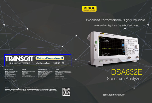
All-Digital IF TechnologyFrequency Range from 9 kHz to 3.2 GHzMin. -148 dBm Displayed Average Noise Level (Typ.) Min. -90 dBc/Hz @ 10 kHz Offset Phase Noise Level Measurement Uncertainty <1.0 dB 10 Hz Minimum Resolution BandwidthUp to 3.2 GHz Tracking Generator (DSA832E-TG) Optional PreamplifierAdvanced Measurement Functions (Opt.)EMI pre-compliance testingVSWR and antenna resonant point testingUse Built-in tracking source to perform economical and efficient incentive responsemeasurement Channel power monitoring and pass/fail verificationMass production requirements for the measurement and monitoring of spectral signals Applicable to RF industrial region, such as R&D, lower cost manufacture industry etc Measurement requirements for electronics fans of spectrum analyzerCombined with the Microwave & RF education and training kit; applicable to RF education field; get to deeply understand the theories by practical operationsAdvantages and CharacteristicsAdvantages and CharacteristicsPrice and Application SolutionsOrdering InformationBrief Technical ParametersPlease contact the RIGOL Regional Sales Manager for further informationFrequency Frequency range 9 kHz to 3.2 GHz Frequency resolution 1 HzSSB Phase Noise20℃ to 30℃, f c =1 GHzCarrier offset10 kHz offset <-90 dBc/HzAmplitude Measurement Range Rangef c ≥10 MHz DANL to +20 dBmDisplayed Average Noise Level (DANL)RBW = VBW = 10 Hz, sample detector, trace average ≥ 50, tracking generator off, 20℃ to 30℃, input impendence = 50 ΩPA OFF <-130dBm (typ.) PA ON <-148dBm (typ.)DistortionSecond harmonic intercept (SHI)f c ≥ 50 MHz, input signal level = -20 dBm, attenuation = 10 dB +40 dBm Third-order intercept (TOI)f c ≥ 50 MHz, two -20 dBm tones at input mixer spaced by 200 kHz, attenuation = 10 dB +7 dBmDescriptionOrder Number Model spectrum analyzer, 9 kHz to 3.2 GHzDSA832E spectrum analyzer, 9 kHz to 3.2 GHz (with tracking generator, factory installed)DSA832E-TG Standard accessoriesquick guide (hard copy)-power cable-Optionspreamplifier, 100 kHz to 3.2 GHz PA-DSA832EMI filter & quasi-peak detectorEMI-DSA800advanced measurement kit AMK-DSA800VSWR measurement kit VSWR-DSA800DSA PC softwareUltra Spectrum Optional accessoriesinclude: N-SMA cable, BNC-BNC cable, N-BNC adaptor, N-SMA adaptor, 75 Ω to 50 Ω adaptor, 900 MHz/1.8 GHz antenna (2pcs), 2.4 GHz antenna (2pcs)DSA Utility Kitinclude: N(F)-N(F) adaptor (1pcs), N(M)-N(M) adaptor (1pcs), N(M)-SMA(F) adaptor (2pcs), N(M)-BNC(F) adaptor (2pcs), SMA(F)-SMA(F) adaptor (1pcs), SMA(M)-SMA(M) adaptor (1pcs), BNC T type adaptor (1pcs), 50 Ω SMA load (1pcs), 50 Ω BNC impedance adaptor (1pcs)RF Adaptor Kit include: 50 Ω to 75 Ω adaptor (2pcs)RF CATV Kit include: 6dB attenuator (1pcs), 10dB attenuator (2pcs)RF Attenuator Kit 30dB high power attenuator, max. power 100W ATT03301HN(M)-N(M) RF cableCB-NM-NM-75-L-12G N(M)-SMA(M) RF cable CB-NM-SMAM-75-L-12G RF demo kit (transmitter)TX1000RF demo kit (receiver)RX1000VSWR bridge, 1 MHz to 2 GHz VB1020VSWR bridge, 1 MHz to 3.2 GHz VB1032VSWR bridge, 800 MHz to 4 GHz VB1040VSWR bridge, 2 GHz to 8 GHz VB1080near field probe NFP-3EMI PC softwareS1210 EMI Pre-compliance Software rack mount kit RM-DSA800soft carrying bagBAG-G1USB to GPIB interface converter for instrumentUSB-GPIBEMI pre-compliance test function(Opt.) EMI Filter & Quasi-Peak Detector Kit (Opt.) VSWR Measurement Kit (Opt.) Optional RF TX/RX Training KitOptional RF Accessories (Cable, Adaptor, Attenuator, Bridge ...) Complete Connectivity: LAN (LXI), USB Host & Device, GPIB (Opt.)8 Inch TFT LCD DisplayCompact Size, Light Weight Design。
HIOKI儀器產品選購指南说明书
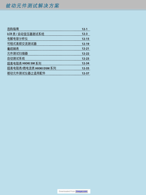
Ⴍ 高速20通道/變壓器L/C/Z/DCR/圈數/短路/平衡掃描測試功能 高速80通道/變壓器L/C/Z/DCR/圈數/短路/平衡掃描測試功能
20通道/變壓器L/C/Z/DCR/圈數/短路/平衡掃描測試功能 3250加LCR錶分析功能 3252 1MHz版
3302加通訊參數測量功能
ٜࠠݴᛌཥݴ๕ / ༊ӻ୕፯ᒅܸی
Ꮠ͜Ⴍ LCD Inverter變壓器(陶瓷電容、線材、PCB)
耐久性測試/耐壓測試/崩潰電壓測試 外部電極螢光燈管(EEFL),背光耐久性/燈管電流測試 交換式電源供應器(SMPS)主變壓器與主動式功率因素修正器
(Active PFC) Choke耐久性測試與電氣特性分析 醫療設備高頻漏電流安規檢驗
ࠫϣ 12-34 12-34 12-34 12-34 12-35 12-35
0.1mΩ ~ 100MΩ 0.1mΩ ~ 100MΩ 0.1mΩ ~ 100MΩ 0.01mΩ ~ 100MΩ 0.01mΩ ~ 100MΩ
3252
20Hz~200kHz
0.1mΩ ~ 100MΩ
3302
20Hz~1MHz
0.1mΩ ~ 100MΩ
Ⴍ 電容量高速檢測 全數位分類,比較器功能,可選無10kHz版 全數位分類,比較器功能
提供高頻高壓交流與直流電源供應的功能,供平面螢光燈(FFL) 與表面傳導電子發射顯示器(SED)裝置分析使用
直流/直流轉換器SMD Power Choke溫昇測試 (直流重疊電流與交流漣波電壓)與電氣特性分析
緩衝電容壽命測試 高壓電容壽命測試 LCD Inverter變壓器(陶瓷電容、線材、PCB)生產線耐壓測試 醫療設備高頻漏電流安規檢驗 車用驅動馬達生產線電暈(Corona)放電檢驗 被動元件(換流器變壓器、陶瓷電容、高壓線材、PCB等) 高頻高壓壽命測試
程控设备清单

序号 设备名称 制造商 型号 单位 数量 安装位置
TS303数字程控交换机系统 1 2 3 4 5 6 7 8 9 10 11 12 13 14 数字中继板 ZXJ10子框母板 Power B 电话机 电话机 电话机 电话机 电话机 电话机 电话机 电话机 指令电话主机(控制台) 音频配线架 音频配线架 深圳中兴 深圳中兴 深圳中兴 TCL TCL TCL TCL TCL TCL TCL TCL Dell、上海纽顿兰 烽火科技 烽火科技 4*2Mbit/s BDT Power B HCD868(17)TSD HCD868(17)TSD HCD868(17)TSD HCD868(17)TSD HCD868(17)TSD HCD868(17)TSD HCD868(17)TSD HCD868(17)TSD MDR9500电话录音系统,电 脑配置为DELL-OptiPlex GX280 3*VDF-128 VDF-128 (128线,含保安单元) 块 块 块 部 部 部 部 部 部 部 部 套 架 架 2 1 2 23 1 9 70 10 60 30 85 1 1 7 各收费站票亭 三明北大厅 三明北备机 夏茂 将乐监控(大厅 6,通信房1,办 公室2) 泰宁 万安 将乐 将乐分中心 将乐分中心 其余通信站点 三明北分中心
bom格式样本

单位 Pcs Pcs Kg Pcs Pcs Kg Pcs Pcs Kg Bao Pcs Pcs Kg Bao Pcs Pcs M Pcs Pcs Pcs Pcs M Pcs Pcs Pcs Pcs M Pcs Pcs Pcs Pcs M Pcs Pcs
类别 F F B F F B F F B B F F B B F P B B B F P B B B F P B B B F P B B B
BOM(物料清单)
生效日期: 母物料: 水平物料是否批核? 水平 .1 ..2 ...3 .1 ..2 ...3 .1 ..2 ...3 ...3 .1 ..2 ...3 ...3 .1 ..2 ...3 ..2 ..2 .1 ..2 ...3 ..2 ..2 .1 ..2 ...3 ..2 ..2 .1 ..2 ...3 ..2 ..2 CDF核 核准: 序号 1 2 3 4 5 6 7 8 9 10 11 12 13 14 15 16 17 18 19 20 21 22 23 24 25 26 27 28 29 30 31 32 33 34 物料编号 1-888-013 1-027-026 6-001-008 1-888-014 1-027-027 6-001-008 1-999-403 1-027-060 6-001-001 7-002-108 1-999-404 1-027-061 6-001-001 7-002-108 9-000-091 5-010-001 5-010-000 9-005-072 9-029-019 9-000-092 5-010-001 5-010-000 9-005-072 9-029-019 9-000-093 5-010-001 5-010-000 9-005-072 9-029-020 9-000-094 5-010-001 5-010-000 9-005-072 9-029-020 2008-5-23 PA0078/W-020-09-AA 门把手,PA-0078 Y 图号 名称 短手柄盖-下 短手柄盖-下 塑胶料,ABS PA-727 长手柄盖-下 长手柄盖-下 塑胶料,ABS PA-727 短手柄盖-上 短手柄盖-上 塑胶料,ABS PA-757,台湾 色粉,光辉,6497 长手柄盖-上 长手柄盖-上 塑胶料,ABS PA-757,台湾 色粉,光辉,6497 包装材料,PA-0078(长手柄盖-上) 封箱胶纸, W=60mm L=3000mm 封箱胶纸, W=60mm 卡通箱,480*410*400mm PVC盒,470*400*55mm,T=0.5 包装材料,PA-0078(长手柄盖-下) 封箱胶纸, W=60mm L=3000mm 封箱胶纸, W=60mm 卡通箱,480*410*400mm PVC盒,470*400*55mm,T=0.5 包装材料,PA-0078(短手柄盖-上) 封箱胶纸, W=60mm L=3000mm 封箱胶纸, W=60mm 卡通箱,480*410*400mm PVC盒,470*400*55mm,T=0.5 包装材料,PA-0078(短手柄盖-下) 封箱胶纸, W=60mm L=3000mm 封箱胶纸, W=60mm 卡通箱,480*410*400mm PVC盒,470*400*55mm,T=0.5 机械工程师: 规格 ABS PA-727 ABS PA-727 ABS ABS PA-727 ABS PA-727 ABS ABS PA-757 ABS PA-757 ABS 色粉 ABS PA-757 ABS PA-757 ABS 色粉 N.A. N.A. N.A. A=A PVC N.A. N.A. N.A. A=A PVC N.A. N.A. N.A. A=A PVC N.A. N.A. N.A. A=A PVC 电子工程师: 材质/颜色 Cr-PLATING NATURAL 塑胶料 Cr-PLATING NATURAL 塑胶料 灰白色 WHITE 塑胶料 WHITE 灰白色 WHITE 塑胶料 WHITE N.A. N.A. N.A. N.A. 透明 N.A. N.A. N.A. N.A. 透明 N.A. N.A. N.A. N.A. 透明 N.A. N.A. N.A. N.A. 透明 版本 AA
Equipment List
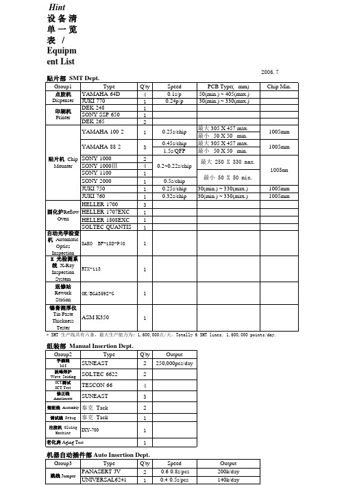
Q'ty 2 2 4 3 2 1 1 1
Output 250,000pcs/day
老化房 Aging Test
机器自动插件部 Auto Insertion Dept.
Type PANASERT-JV 跳线 Jumper UNIVERSAL6241 PANASERT-AE 卧式 Axial PANASERT-AVB UNIVERSAL6241B PANASERT-RH 立式 Radial PANASERT-RH6 Group3 Q'ty 2 1 2 2 1 2 1 Speed 0.6-0.8s/pcs 0.4-0.5s/pcs 0.6-0.8s/pcs 0.6-0.8s/pcs 0.4-0.5s/pcs 0.8-0.9s/pcs 1.0-1.2s/pcs Output 200k/day 140k/day 200k/day 170k/day 120k/day 165k/day 78k/day
贴片部 SMT Dept.
Type YAMAHA-64D JUKI-770 DEK-248 印刷机 Printer SONY SSP-650 DEK-265
点胶机 Dispenser
YAMAHA-100-2 YAMAHA-88-2
贴片机 Chip SONY-1000 Mounter SONY-1000Ⅲ
1005mm 1005mm
SONY-1100 SONY-2000 JUKI-750 JUKI-760 HELLER-1700 固化炉Reflow HELLER-1707EXC 固化炉 Oven HELLER-1808EXC SOLTEC-QUANTIS
自动光学检查 机 Automatic SAKO BF-18D-P40 Optics Inspection X 光检测系 统 X-Ray RTX-113 Inspection System 返修站 OK/BGA3592-G Rework Station 锡膏测厚仪 Tin Paste ASM K350 Thickness Tester
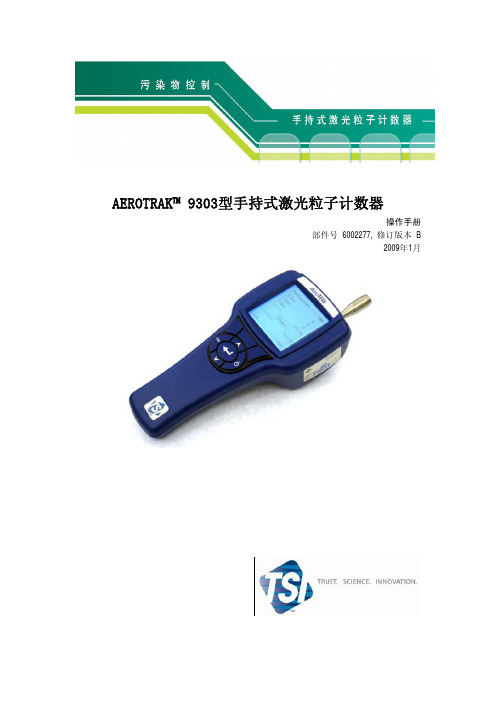
9303中文说明书
目录
手册修订历史...................................................................................................................................3 声明 ..................................................................................................................................................4 安全信息...........................................................................................................................................7
光源激光二极管分钟满足jisb9921流量01cfm283lmin校准nist溯源采样探头管等速采样探头采样模式手动和自动采样时间秒至99分59采样频率1999次或连续采样输出内部hepa过滤器真空源内置泵通讯方式usb输出数据存储1500个记录状态提示电量不足或维修显示36英寸160160单色lcd主机外壳高耐磨注塑电源110240vac5060hz通用线路功率及各国适用的插头电池可充电锂离子电池电池工作时间连续使用45小时以上充电时间小时主机尺寸lwh916324in231162cm不包括等速取样入口重量13lbs058kg含电池标准cejisb9921iso215014保修期年
前述保证将代替其他的担保并且受制于规定的限制。不可作出其它表述,或为特定目的 或商业利益而对保证权限作出曲解。在法律的规定的范围内,用户或买方享有索取赔偿的权 利,卖方对商品的所有损失,损坏或损害(包括以合同为基础所作的声明、疏忽、侵权行为、 严格的义务或其它)承担责任,卖方可将商品返还卖方,卖方偿还买方购买资金或卖方选择 对商品进行维修或替换。卖方对商品特殊的、重大的或意外损伤不承担任何责任。卖方不承 担任何由安装、拆卸或重新组装所造成的花销或费用。在多种因素导致法律诉讼时不得对卖 方提出任何形式超过12个月以上的诉讼。在卖方承担风险的前提下,返还到生产厂家的产品 由买方承担损失风险,如有损坏将被退回,否则,卖方承担损失风险。卖方及所有的使用者 都必须接受该保证及责任权限,该权限包含了卖方所有的保证责任或特殊的有限度的质量保 证。在未得到卖方相关负责人签署的书面材料的情况下,不得擅自对该保证及责任权限进行 补充,修改或放弃使用其条款。 维修政策
配置清单及技术指标
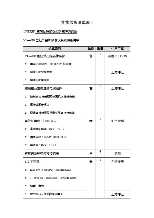
货物供货清单表1货物名称: 窑筒体扫描仪(红外窑炉热像仪)YL—IIB型红外窑炉热像仪系统供货清单:注:贵州普定明达、贵州遵义华峰、云南华宁珠山、云南普洱、云南曲靖际丰、云南易门大椿树、云南元江等水泥生产线已选用。
供货单位:上海德运光电技术有限公司主要技术性能指标货物名称:窑筒体扫描仪(红外窑炉热像仪)•设备制造厂名称:上海德运光电技术有限公司•规格及型号:YL—ⅡB型•红外线扫描摄像头部:•制造厂名称:上海德运光电技术有限公司•规格及型号:YL—ⅡB型•红外探测器:美国JUDSON J15TE碲镉汞、多级半导体制冷•扫描方式:光学线扫描•扫描频率:25线/秒•扫描角度:自适应,最大110°•聚焦范围:10米~≦•空间分辨率:2毫弧度•测温范围:100℃~500℃•温度分辨率:<1℃(200℃黑体)•重复性:±1℃•工作方式:连续•输出信号:线扫描温度信号、行同步信号等•使用环境:环境温度:-25℃~45℃;野外现场:避免太阳直射•体积与重量:Ф200×380毫米;摄像头12公斤•红外图像采集卡:•制造厂名称:上海德运光电技术有限公司•规格及型号:HW Blaster•多路输入信号:线扫描温度信号、行同步信号、窑转速信号等•高速高精度A/D转换器,最高采样数率:4M/S•8位I/O•支持MS-Win32、Win98、WinNT、Win2000•计算机及配置:(以供货清单为准)•制造厂名称:台湾凌华•规格及型号:610工控机•计算机配置:Intel PⅣ2.4G CPU,256MB RAM1.44 FD,80G HDD,48X CD-ROM键盘,鼠标•系统软件:(详见后所附技术文本)•制作及版权所有:上海德运光电技术有限公司•版本信息:Model 2000,Windows98版•图像显示:实时显示温度线性化、图像几何校正•图像刷新频率:同步刷新(与窑转速同步)•图像象元数:400×200•软件功能:•图像显示:窑平面温度展开图及水平/垂直波形图、温度分布三维显示图、炉衬厚度显示图、历史记录图像回放•温度测量:点温、波形、单温、放大、区域•温度报警:分段高温报警温度设定、红窑温度报警设定•记录回顾:窑最高/平均/最低温度曲线回顾、点温回顾、图像回放、红窑回放•输出:打印日报表、打印温度曲线、红窑报警打印输出投标货物清单表2.1货物名称:工业电视(窑头高温工业电视)ITV-2005HA型高温工业电视供货清单:供货单位:上海德运光电技术有限公司主要技术性能指标货物名称:工业电视(窑头高温工业电视)•制造厂名称及地址:上海德运光电技术有限公司•规格及型号:ITV-2005HA型•电源电压(V):~220V•允许环境温度(℃):≤60℃•环境湿度:≤90%•不锈钢高温防护外壳:•材料:工业不锈钢•结构:整体双层水冷套,气浴,前端窥孔后端拆卸•使用环境:耐温:150℃,并伴有不可予见的正压瞬时高温火焰出现,火焰温度可达1200 ℃;耐压:86~106Kpa / 常压•外型尺寸:Φ135×365mm•防护外壳回撤装置:•结构:电动回撤/固定式,自动开关闸门•使用环境:耐温:150℃,并伴有不可予见的正压瞬时高温火焰出现,火焰温度可达1400 ℃;耐压:86~106Kpa / 常压•摄像头回撤方式:电动回撤•行程:0.4米•关闭窥孔方式:电动开/关闸门•行程时间:< 5 秒•外型尺寸:架长•不锈钢安装底板:•材料:工业不锈钢•结构:双层隔水套,窥孔气浴、闸门•使用环境:耐温:150℃,并伴有不可予见的正压瞬时高温火焰出现,火焰温度可达1400 ℃;耐压:86~106Kpa / 常压•窥孔:外部直径Φ60mm、气吹扫、闸门开/关•外型尺寸:590×220×40mm•彩色摄像机型号:松下WV-CP484•CCD成像面积:1/3英寸,752×582象素•彩色CCD水平解析力:480线•系统水平清晰度:≥400线•信噪比(dB):50Db•最低照度:0.5Lux (F1.2时),0.6Lux (F1.4时)•视频输出:1Vp-p PAL同步复合,75Ω•高温针孔镜头•分立式蓝宝石保护镜片•焦距:4~20mm 变焦•F数:2.5~12.5•视场角:74度~17度•针孔直径:Φ1.6mm,配蓝宝石防护镜•外型尺寸:Φ20×99mm•现场电水气控制柜•电水气控制、油水分离器•防护外壳内部温度显示和高温报警、外部高温报警、低水压低气压报警等•摄像机设置控制•手动开/关闸门•中控室远程控制器通讯•中控室远程控制器•防护外壳内部温度显示和高温报警、外部高温报警、低水压低气压报警•摄像机设置控制•手动执行开/关闸门货物清单表2.2货物名称:工业电视(蓖冷机高温工业电视)ITV-2005HN型内窥式高温工业电视供货清单:供货单位:上海德运光电技术有限公司主要技术性能指标货物名称:工业电视(蓖冷机高温工业电视)•制造厂名称及地址:上海德运光电技术有限公司•规格及型号:ITV-2005HN型•电源电压(V):~220V•允许环境温度(℃):≤60℃•环境湿度:≤90%•不锈钢高温防护外壳:•材料:工业不锈钢•结构:整体双层水冷套,气浴,前端窥孔后端拆卸•使用环境:耐温:150℃,并伴有不可予见的正压瞬时高温火焰出现,火焰温度可达1200 ℃;耐压:86~106Kpa / 常压•外型尺寸:Φ135×365mm•防护外壳回撤装置:•结构:电动回撤/固定式,自动开关闸门•使用环境:耐温:150℃,并伴有不可予见的正压瞬时高温火焰出现,火焰温度可达1400 ℃;耐压:86~106Kpa / 常压•摄像头回撤方式:电动回撤•行程:0.4米•关闭窥孔方式:电动开/关闸门•行程时间:< 5 秒•外型尺寸:架长•不锈钢安装底板:•材料:工业不锈钢•结构:双层隔水套,窥孔气浴、闸门•使用环境:耐温:150℃,并伴有不可予见的正压瞬时高温火焰出现,火焰温度可达1400 ℃;耐压:86~106Kpa / 常压•窥孔:外部直径Φ60mm、气吹扫、闸门开/关•外型尺寸:590×220×40mm•彩色摄像机型号:松下WV-CP484•CCD成像面积:1/3英寸,752×582象素•彩色CCD水平解析力:480线•系统水平清晰度:≥400线•信噪比(dB):50Db•最低照度:0.5Lux (F1.2时),0.6Lux (F1.4时)•视频输出:1Vp-p PAL同步复合,75Ω•高温针孔镜头•分立式蓝宝石保护镜片•焦距:4~20mm 变焦•F数:2.5~12.5•视场角:74度~17度•针孔直径:Φ1.6mm,配蓝宝石防护镜•外型尺寸:Φ20×300mm•现场电水气控制柜•电水气控制、油水分离器•防护外壳内部温度显示和高温报警、外部高温报警、低水压低气压报警等•摄像机设置控制•手动开/关闸门•中控室远程控制器通讯•中控室远程控制器•防护外壳内部温度显示和高温报警、外部高温报警、低水压低气压报警•摄像机设置控制•手动执行开/关闸门。
售后服务能力
8、售后服务能力1、技术支持售后服务体系作为业内享有良好声誉的安防设备生产厂商,我公司有能力及时向用户提供高质量的产品和优良的售后服务。
为了保证优质及时的服务实现,我公司在全国范围内已经成立一支受到良好培训并富有非常丰富工作经验的工程师队伍,对用户采购的产品提供一线售后技术支持。
1)服务理念----全程全面全天候专业化服务服务体现了浩云公司一个品牌的实力和承诺,凭借雄厚的实力,全心全意为客户提供售前、售中和售后服务,尽心尽力保障用户设备正常使用。
2)服务宗旨----服务第一、顾客至上浩云公司奉行“服务第一、顾客至上”的服务宗旨,时刻以客户利益为重,处处为客户着想,不断地开拓创新,为客户创造价值。
3)服务规范----诚信、专业、高效、迅捷为更好地服务客户,浩云公司建立了标准、规范的客户服务体系,为客户提供高效、迅捷的优质服务,力争以全面、细致的服务让客户满意,进一步增强客户对浩云公司的信心与认同。
4)服务承诺浩云公司承诺产品自销售之日起,凡属产品质量问题一个月包换,肆年免费保修。
但下列情况不在保修范围之内,但用户仍可享受本公司提供的维修服务,但所需更换的零件费用及检修费由用户承担。
1、无保修卡或擅自涂改保修卡的。
2、一切人为损坏如:接入不适当电源、不依说明书使用、因意外而造成损坏、非经本公司认可之维修或改装、不适当之安装等,保修立即失效。
3、面壳划伤碰损等现象不在包换之列。
4、保修卡上的产品型号和编号与商品实物不相符合的。
5、因不可抗力因素如地震、火灾、水灾等造成的损坏。
5)服务保障1、售后服务实行7*24小时服务,若产品发生故障,先通过电话、网络进行远程技术支持,如果问题还没解决,售后服务工程师会在最短时间内到现场解决问题。
2、浩云公司拥有各类专业技术人员,根据需要,售后服务工程师可向公司各职能部门随时申请专业技能人员,派往用户所在地,提供及时、优质的服务。
3、公司提供种类齐全的备品备件,及时、迅速的将售后服务所需备品备件送到用户所在地进行设备更换维修。
FOT-930 MaxTester多功能损耗测试器的产品介绍说明书

FasTesT: three-wavelength measurement of optical loss, ORL and fiber length in 10 secondsAll-in-one portable test solution: up to eight instruments combined in a single, eye-catching handheld packageFTTx ready: allows for the testing of passive optical networks (PONs) at 1310 nm, 1490 nm and 1550 nm, the three ITU-T G.983.3 recommended wavelengths for PONsCost of ownership: lowest in the industry, thanks to three-year warranty and recommended calibration interval, error-free testing and minimized training timeMultifunction Loss TesterFOT-930 MaxTester 800-404-ATEC (2832)E s t a b l i s h e d 1981The new FOT-930 MaxTester Multifunction Loss Tester is designed to help network service providers address CAPEX and OPEX issues, enable installers to easily adapt to all network types, and provide CATV operators with a single-unit solution to their backreflection, fiber-length, high-power and bidirectional loss measurement needs. Combined with its video fiber inspection probe, this unit also enables the easy detection of dirty or damaged connectors, providing a clear view of connectors and fiber ends on the FOT-930’s high-resolution display.EXFO’s Next-Generation MaxTester: Much More Features, Much Bigger PerformanceAll-in-one unit: combines up to eight instrumentsFuture-proof: next-generation features meeting the latest industry requirementsWith countless configurations available, the FOT-930MaxTester is the handheld unit of choice for today’s network service providers, fiber-optic network installers/contractors and CATV operators.FOT-930 MaxTesterWhile performing FasTesT measurements, the FOT-930 can launch automated loss and ORL measurements on all three wavelengths andperform fiber-length measurements.The FOT-930’s Windows-like, 320 x 240 color interface provides first-class user-friendliness.The video fiber inspection probe enables quick, easy inspection of fiber endsor connectors. View is displayed on the FOT-930’s high-resolution display.Key Features"Two FasTesT ports: a three-wavelength singlemode port, including either 1625 or 1490 nm, and a two-wavelength multimode port, for a total of up to five wavelengths"Automatic measurement of ORL and fiber length during FasTesT "Visual loss and ORL pass/fail analysis "Field-swappable rechargeable batteries "Easily accessible connectors "Large 320 x 240 color screen"Storage of over 1000 complete test reports, with automated report generation"Options: high-power detector, talk set, visual fault locator (VFL) and video fiber inspection probe "No offset nulling requiredThe FOT-930 lets you use a high-power source, a high-power power meter, as well as a talk set and visual fault locator combination, all at once.Network Service Providers: Addressing CAPEX and OPEX ConcernsTalk Set PortFor crystal-clear voice communication.Power Meter Detector Port Compatible with almost every connector on the market. Manually and efficiently perform power and loss testing. Accurately measure power up to 26 dBm.Perform loss, ORL and fiber length measurements for up to three SM wavelengths on one port, and for two MM wavelengths on a second port. VFLBuilt-in 650 nm visual fault location on a universal connector.FOT-930 MaxTester CATV Operators: One Unit for All Backreflection, Fiber-Length and Loss Measurement NeedsAs video-on-demand is on the verge of becoming the next big thing, bandwidth and distance are increasing and fiber tolerances are becoming more and more stringent. Related analog transmission systems use high power up to 26 dBm. As a result, network engineers need to worry about potentially high backreflection—mostly caused by dirty or damaged connectors—and perform fiber-length measurements.In short, CATV test crews need a backreflection meter, an OTDR (for measuring fiber length), a video fiber inspection probe and a bidirectional, dual- or triple-wavelength loss meter. Choosing the FOT-930 combines all these functionalities in a compact, easy-to-carry unit.Key Advantages for CATV Operators•Automated ORL measurement based on pass/fail thresholds•GeX detector, for high-power measurement up to 26 dBm•Video fiber inspection probe, for easy viewing of connectors and fiber ends on the FOT-930’s high-resolution displayThe FOT-930’s colored pass/fail indicators help you quickly identifyunacceptable ORL values..Full Report Generation in a SnapThe FOT-930’s software automatically sets up test data in an easy-to-read, well-organized table. Testing is simplified thanks to the highly intuitive user interface and integrated test functions, taking software user-friendliness to the next level.•Select predefined test parameters and pass/fail thresholds•Customize user settings and cable identification parameters•Add operator comments•Generate reports for ORL, bidirectional loss (three wavelengths) and fiber length measurementReport GenerationGrowing fiber deployment in NSP and CATV networks sometimes leads installation companies to hire subcontractors. These subcontractors must produce proper test documentation to corroborate the tests were performed as specified.EXFO’s FOT-930 MaxTester easily and efficiently provides complete, high-quality test documentation. Its data logging and management features help users quickly access and download test results to any PC through the RS-232 port for in-depth analysis and first-class report generation.Display comprehensive test results thanks to ToolBox data management software.FasTesT ReportSpecifications1(Preliminary)External Power Meter FOT-932FOT-932X FOT-933Detector type Ge GeX InGaAsMeasurement range (dBm)10 to -7026 to -55 6 to –73Range displayed (dBm)Down to -90Down to -75Down to -90Uncertainty2, 3±5 % (±0.1 nW)±5 % (±3 nW)±5 % (±0.05 nW)Wavelength range (nm)800 to 1650800 to 1650800 to 1650Display resolution2(dB)0.010.010.01Calibrated wavelengths404040Recommended recalibrationperiod (years)333Automatic offset nulling4Yes Yes YesSources Standard-4-5-12C (second port)-12D (second port)Wavelengths (nm)1310 ±201310 ±201310 ±20850 ±25850 ±251550 ±201550 ±201490 ±101300 +50/–10 1300 +50/–101625 ±151550 ±20Emitter type Laser Laser Laser LED LEDMinimum output power5(dBm)-3.5/-3.5-3.5/-7/-7-3.5/-7/-7-26.5/-26.5 (50/125 µm)-24.5/-24.5 (62.5/125 µm)Spectral width6(nm)≤5/≤5 ≤5/≤5/≤5≤5/≤5/≤550/13550/135Stability7(8 hours) (dB)±0.05±0.05±0.05±0.05±0.05FasTest Standard-4-5-12C(second port)-12D(second port)Wavelengths (nm)1310 ±201310 ±201310 ±20850 ±25850 ±251550 ±201550 ±201490 ±101300 +50/–10 1300 +50/–101625 ±151550 ±20Loss range8(dB)6060604345Loss precision9(repeatability) (dB)Side-by-side0.150.150.150.250.25Loopback0.250.250.250.450.45Length measurement range (km)20020020055Length measurement uncertainty10±(10 m + 1 % x distance)Dedicated ORL All SM wavelengthsORL range9(APC / UPC) (dB)65 / 55ORL uncertainty11(dB)±0.5Resolution2(dB)0.01General SpecificationsSize (H x W x D) 25.0 cm x 12.5 cm x 7.5 cm (97/8in x 4 15/16in x 3 in)Weight 1kg(2.2lb)Temperature operating –10 °C to 50 °C (14 °F to 122 °F)storage –40 °C to 70 °C (–40 °F to 158 °F)Storage capacity 1024 complete testsRelative humidity 0 % to 95 % non-condensingPower9Li-ion battery 9 hours3 hours to fully recharge when unit is offWarranty (years)3FOT-930 MaxTesterNotes:1.At 23 °C ±1 °C and 1550 nm with FC/PC connector unless otherwise specified.2.Resolution, uncertainty and linearity are functions of input power; uncertainty isvalid at calibration conditions.3.Traceable to NIST; up to 20 dBm for GeX.4. Power of > –45 dBm for Ge, > –30 dBm for GeX and > –57 dBm for InGaAs.5. In high-power mode.6. As defined by Telcordia TR-TSY-000887, rms for lasers and at -3 dB for LEDs;typical values for LEDs.7.After a warm-up time of 6 minutes.8. Typical value, at 1550 nm for SM and 850 nm for MM.9.Typical value.10.For fiber length ≤120 km.11.Typical value, for APC connectors.12.In graded-index MM fibers.Talk setEmitter type Laser Wavelength (nm)1550 ±20 Dynamic range at 1550 nm (dB)45 Dynamic range MM12(dB)40VFL9Emitter type Laser Wavelength (nm)650 Output power (dBm)3Standard AccessoriesUser guide, AC adapter/charger, 2 Li-ion batteries, shoulder strap, Certificate of Calibration, connector adapter (FOA) according to chosen connector, mandrel, RS-232 cable and software, soft carrying case and alcohol cleaning pads.CORPORATE HEADQUARTERS 400 Godin AvenueVanier (Quebec) G1M 2K2 CANADA Tel.: 1 418 683-0211 ·Fax: 1 418 683-2170EXFO AMERICA 4275 Kellway Circle, Suite 122Addison TX 75001 USATel.: 1 800 663-3936 ·Fax: 1 972 836-0164EXFO EUROPE Le Dynasteur, 10/12 rue Andras Beck 92366 Meudon la Forêt Cedex FRANCE Tel.: +33.1.40.83.85.85 ·Fax: +33.1.40.83.04.42EXFO ASIA-PACIFIC 151 Chin Swee Road, #03-29 Manhattan HouseSINGAPORE 169876Tel.: +65 6333 8241·Fax: +65 6333 8242EXFO CHINABeijing New Century Hotel Office Tower, Room 1754-1755 Beijing 100044 P . R. ChinaTel.: +86 (10) 6849 2738 · Fax: +86 (10) 6849 2662No. 6 Southern Capital Gym Road TOLL-FREE (USA and Canada)Tel.: 1 800 663-3936 • *************SPFOT930.1AN © 2004 EXFO Electro-Optical Engineering Inc. All rights reserved. Printed in Canada 04/02EXFO is certified ISO 9001 and attests to the quality of these products. EXFO has made every effort to ensure that the information containedin this specification sheet is accurate. However, we accept no responsibility for any errors or omissions, and we reserve the right to modify design,characteristics and products at any time without obligation.Units of measurement in this document conform to SI standards and practices.Contact EXFO for prices and availability or to obtain the phone number of your local EXFO distributor.For the most recent version of this spec sheet, please go to the EXFO website at /support/techdocs.asp In case of discrepancy, the Web version takes precedence over any printed literature.。
供货范围货物清单

供货范围(货物清单)
主要技术要求
除主要设备外,清单中各类设备安装及配套所需的配件与辅材数量为参考数据,应以实地考察后得到的实际数据投标,招标完成后采购方不因固有工程量增加而承担任何费用,费用将以中标价结算,请投标人充分考虑风险性。
建议投标人到用户单位进行现场勘察,以明确施工场地情况并准确了解相关工程量等。
注:注意事项:
1、招标人提供的清单中材料所涉及品牌或型号(如有),仅供投标人参考。
投标人在投标时可以选用其它品牌,但所选用的品牌产品要在实质上相当于或不低于参照品牌技术性能的要求,并且使采购人满意。
2、提供相同品牌产品且通过资格审查、符合性审查的不同投标人参加同一合同项下投标的,按一家投标人计算,评审后得分最高的同品牌投标人获得中标人推荐资格;评审得分相同的,以投标报价最低的获得中标人推荐资格。
3、非单一产品采购项目,采购人应当根据采购项目技术构成、产品价格比重等合理确定核心产品,并在招标文件中载明。
多家投标人提供的核心产品品牌相同的,按第2条款规定处理。
拟投入本任务的主要安全设备列表

拟投入本任务的主要安全设备列表
1. 闭路监控系统
- 数字视频监控设备,包括高清摄像机和录像设备
- 多路视频监控系统,支持实时监视和录制功能
- 监控中心控制台,配备显示屏和控制设备
2. 入侵报警系统
- 门窗磁控器,用于感知门窗的开关状态
- 人体红外探测器,用于探测房间内的移动物体
- 报警主机,用于管理和响应报警信号
- 报警器,用于发出警报声音和光亮信号
3. 门禁系统
- 门禁控制器,用于控制门的开关状态
- 门禁读卡器,支持刷卡和密码开门
- 门禁管理软件,用于管理门禁权限和生成报表
4. 消防报警系统
- 烟雾探测器,用于探测烟雾和火焰
- 温度探测器,用于探测房间内的温度变化
- 报警联动控制器,用于联动报警设备和灭火系统
- 消防主机,用于管理和响应火警信号
5. 安全门禁系统
- 电子门锁,支持刷卡、密码和指纹开锁
- 门禁交换机,用于管理多个门禁点的联网通信
- 门禁读卡器,支持身份验证和记录访问日志
6. 安防巡检系统
- 巡检终端,配备高清摄像头和巡检软件
- 巡检管理软件,用于分配巡检任务和生成巡检报告
以上是拟投入本任务的主要安全设备列表。
这些设备将提供全面的安全监控和保护措施,确保任务场所的安全和保密。
济南达科力华机械设备有限公司电动调节阀产品手册说明书

济南达科力华机械设备有限公司(第五版)(提示:请妥善保管,以备急需,遗失不补!)电动调节阀产品手册书中国·山东电话:0531-6869 0668济南达科力华机械设备有限公司主要从事供热节能方面的技术及产品开发;水处理等行业和领域的技术研发、设备制造和工程实施、方案设计、技术服务等工作。
包括西门子温控阀、西门子温控器西门子电动执行器等相关技术咨询、暖通及热能设备销售、安装与调试,西门子温控阀可实现无人值守,超温报警,温度补偿等人性化控制。
济南达科力华机械设备有限公司还是依托省农科院兴办的集科、工、贸于一体的科技型高新技术企业,在工厂化养殖自动化控制领域(食用菌、花卉等)、食品加工等与省农科院深度合作,在温度、湿度、气体浓度、压力等自动控制上取得良好的效果,得到广泛认可。
公司同时代理德国西门子楼宇科技产品,为暖通空调设备厂家及工程公司提供售前、售中和售后服务工作,为广大用户提供优良产品和优质服务。
公司秉承“诚信至上,以人为本,效率优先,服务社会”的办企原则,以优质的产品和高效的售后服务回报广大客户。
路漫漫其修远兮,吾将上下而求索。
孜孜耕、默默前行,是我们永远不变的敬业精神;自强不息,敢于亮剑是我们永远不变的创业精神。
电动温控阀,自力式温控阀,电动二通阀,电动三通阀电动调节阀,减温减压装置,电动减压阀,全自动软化水电动压差旁通阀,高频电子水处理,楼宇自控系统、工厂化养殖自控系统解决方案,工业生产温控、压控、气控等系统解决方案。
企业宗旨:一切以用户体验为导向,以用户价值为中心!企业文化:一步一步,脚踏实地绿色环保节能高效一、产品介绍根据现场情况的不同,选用达科力华电动阀,能够满足空调制冷、换热供暖、通风等控制系统的需要,达到调节温度、压力、湿度及流量的目的。
也广泛适用于石油、化工、冶金、纺织、印染等工业现场的自动控制。
二、产品特点达科力华电动阀采用进口执行器、控制器、传感器,阀门采用平衡式单阀座结构,能够抵消阀门内部高压降产生的推力,有效解决高压现场关断力的问题,降低了执行器的负荷,延长了机器寿命。
北京国际工程咨询有限公司_企业报告(代理机构版)

6
首都师范大学附属育新学校房山分 校 2023 年信息化建设预算项目
北京市房山区教育委 员会
7881.2 7200.0
2023-07-27 2023-07-31
7
清华大学高通量多束扫描电子显微 镜购置项目(清设招第 2022726 号)
清华大学
中标公告
5500.0
2022-12-23
本报告于 2023 年 08 月 21 日 生成
18
2022 年延庆区农村地区村庄冬季清 洁取暖项目
北京市延庆区农业农 村局
19 奔驰 MFA 物业外包服务中标公告
北京鹏盛物业管理有 限公司
3670.0 3568.8 3500.0 3400.0 3400.0 3209.8 3116.9 3036.0
2022-12-22 2023-06-28 2022-11-02 2022-12-14 2022-12-26 2022-09-22 2022-08-24 2022-12-02
1.4 大额项目列表
序号
项目名称
招标单位
预算金额(万元) 公告时间
1
北京市海淀区教师进修学校附属房 山实验学校二次装修改造项目(监 理)成交公告
北京市海淀区教师进 修学校附属房山实验 学校
800000.0
2023-07-24
2
[公开]北京工商大学改善办学保障条 件-整促改落地项目-经济学院整建
北京工商大学
*平均节支率是指,项目节支金额与预算金额的比值的平均值。(节支金额=项目预算金额-中标金额)
本报告于 2023 年 08 月 21 日 生成
1 / 41
1.2 代理项目趋势
近 3 月(2023-06~2023-08):
