SDI中文操作手册
P150-SDI中文说明书_新_
高清3G/HD-SDI监视器15.0″ 高分辨率监视器尊敬的用户:欢迎使用本公司生产的摄影,广播传媒等配套的彩色液晶监视器,本监视器采用先进的集成电路与专业的TFT LED液晶屏,具有高亮度、功耗低、性能稳定、无辐射等优点。
本监视器有多种安装方式,可配套折叠支架作为桌面式监视器使用,监视器的背面预留有VESA(100*100mm;75*75mm)安装孔 侧面的四个方向留有1/4英寸螺丝孔,客户可以根据自己的需要,安装各种款式的固定支架。
本监视器不但具备有SDI(可选)、HDMI ,分量COMPONENT(YpbPr),复合Video,音频Audio多种信号输入,还具有SDI(可选),分量COMPONENT(YpbPr), 复合Video,音频Audio多种信号输出端口。
可以满足不同的用户需求。
产品特点:◆ 峰值辅助对焦◆ 佳能5D MarkII 模式(CAMERA)◆ 画面放大/缩小,镜像翻转功能◆ 画中画功能◆ 行场消隐◆ Tally 指示灯◆ 前置耳机孔◆ 单色显示:彩色、黑色,红,绿,蓝,关◆ 画面比例 全景,全真模式,4:3,满屏,缩放1,缩放2◆ 扫描模式: 标准,欠扫描,过扫描◆ 框形标记:关,96%,93%,90%,85%◆ 显示像素与屏幕像素点对点为了可靠的、长期的正常使用,达到最佳视听效果,请认真阅读本使用说明书注意事项1. 请采用随机配置的电源适配器,如果因为需要,请注意提供合格的电源。
.2. 不要将机子放于日光下爆晒,也不要在过冷过热或潮湿的地方存放、使用.3. 使用时显示屏幕应避开强光照射,以保证图像效果及机子的长期使用.4. 机子内部虽有防震保护措施,但还应避免剧烈碰撞。
5. 不要用化学试剂或溶剂擦洗机子.请用软布擦除机子上的尘污,以保证本机的亮丽.6. 机内无用户可调组件,非专业人员,请勿自行打开本机或自行尝试修理本产品!以免造成不必要的损坏.目 录1.前面板功能示意图---------------------------32.后面板功能示意图---------------------------43.按键操作说明-------------------------------54.功能菜单简介-------------------------------55.信号格式列表-------------------------------96.SDI支持模式表-----------------------------97.电源输入方式------------------------------108.TALLY的使用与连接------------------------119.随机附件----------------------------------1210.故障探寻与排除---------------------------1311.产品技术参数---------------------------- 141.前面板功能示意1.电源指示灯2.►:音量加大调整,在OSD菜单中为确认键与数值增加3.◄:音量减小调整,在OSD菜单中为确认键与数值减小4.:图像暂停键,在OSD菜单中为调整项选择键(向下)5.: 单击该键为辅助对焦功能,双击时为图像放大键,在OSD菜单中为调整项选择键(向上)6.MENU: 菜单键7. B / W:图像的彩色、黑白、单色(红、绿、蓝)切换键8.16:9/4:3:; 图像画面比例调整键9.CAMERA:摄影模式确认键10.SCALE: 框形标记选择键11.MODE:输入信号选择键12.: 耳机插口 (音频输出)13.TALLY(提示灯)2.后面板功能示意图● 后面板功能说明1、 HDMI 高清信号输入2、4、6、 分量Ypbpr输入3、5、7 分量Ypbpr输出8、 复合视频信号输入9、 复合视频信号输出10、11. 音频输入(左右双声道)12、 3G-SDI输入(可选)13、 3G-SDI输出(可选)14、 电源DC12V输入15、 电源开关16、 TSLLY信号输入17、 电池扣板3. 按键操作说明如果在工作状态下按下机子的“”键,即进入相应的OSD菜单操作按本机上的“”或“”键来选择所需查看或调整的选项:(显示效果)(声音)(系统设置)(扫描位置调整),在选择相应的选项后,按动本机上的“”或“”键进行确认,,如果需要退出OSD菜单,则再按一次“”4、功能菜单简介●显示效果设置 (本设置有2页菜单)按“”键,出现以下的OSD菜单,“”或“”键来选择,按动“”或“”键确认,以“”或“”键选择调整项目,然后再用“”或“”键进行各调整量的调整或选择。
SDI使用说明
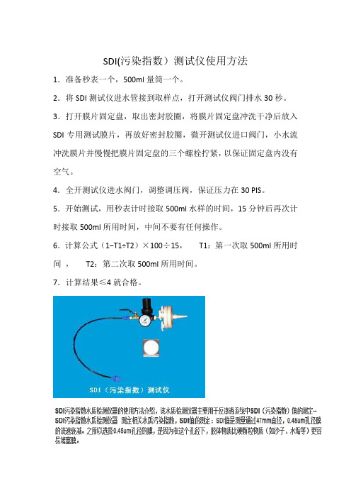
SDI(污染指数)测试仪使用方法
1.准备秒表一个,500ml量筒一个。
2.将SDI测试仪进水管接到取样点,打开测试仪阀门排水30秒。
3.打开膜片固定盘,取出密封胶圈,将膜片固定盘冲洗干净后放入SDI专用测试膜片,再放好密封胶圈,微开测试仪进口阀门,小水流冲洗膜片并慢慢把膜片固定盘的三个螺栓拧紧,以保证固定盘内没有空气。
4.全开测试仪进水阀门,调整调压阀,保证压力在30 PIS。
5.开始测试,用秒表计时接取500ml水样的时间,15分钟后再次计时接取500ml所用时间,中间不要有任何操作。
6.计算公式(1−T1÷T2)×100÷15,T1:第一次取500ml所用时间,T2:第二次取500ml所用时间。
7.计算结果≤4就合格。
SDI的另一种算法。
SDI 标准与程序手册第6部分:SDI 表单9版本0123说明书
61.1 Scuba Diver Registration FormUse this form for the following:1. Open Water Scuba Diver2. Junior Open Water Scuba Diver3. Advanced Scuba Diver4. Master Scuba Diver5. Rescue Diver6. Specialty (Remember to specify which specialty)When using the student registration form, fax or scan and email to SDI Headquarters; the student cards will be returned in the mail.Students can also be registered through the members’ section of International Training Inc website.When registering on-line the cards will be returned in the mail unless the facility has an in-store certification card printer. When using the in-store certification card printer, certification cards are printed and issued immediately to the students.1.2 General Liability Release and Express Assumption of Risk FormsUse this form to obtain the general liability release and assumption of risk from the students. Make sure to review the contents before starting on a course or specialty to ensure it has been completed and signed – including the signature of a witness.Each course the student participates in requires a separate waiver release.1. SDI General Liability Release and Express Assumption of Risk – forTeaching2. SDI General Liability Release and Express Assumption of Risk - ForGuided Scuba Tours for Certified Divers3. SDI General Liability Release and Express Assumption of Risk - ForGuided Snorkeling Tours4. SDI General Liability Release And Express Assumption of Risk - ForUnguided and Unsupervised Boat Dives for Certified Divers5. International Training General Liability Release and ExpressAssumption of Risk – For non-SCUBA courses6. International Training Notice To The Minor Child’s Natural Guardian1.3 Notice To The Minor Child’s Natural GuardianUse this form when teaching or supervising minors in the US state of Florida. This release is used in conjunction with the appropriate liability release for the specified activity or course.1.4 Specialty Upgrade Form for Assistant Instructors and InstructorsUse this form to file for specialty upgrades.1.5 Open Water Global Referral FormUse this form to when a student is traveling to another facility for the open water certification. The procedure is covered in Part 2 – SDI Diver Standards Section 6 Open Water Scuba Diver Standards.1.6 Solo Release FormUse this form as the Solo Diver Liability Release.1.7 Accident / Incident Report FormUse this form to file information regarding an accident or incident with SDI Headquarters.1.8 Academic Presentation FormUse this form when preparing for the academic portion of a class. An example of its usage can be found in the academic portion of the Open Water Instructor Manual.1.9 In-Water Presentation FormUse this form when preparing for the confined portion of a class. An example of its usage can be found in the in-water portion of the SDI Open Water Scuba Diver Instructor Manual.1.10 Member Update FormUse this form when renewing if a membership or teaching status has lapsed after 2 years not teaching.1.11 Dive Leader ApplicationUse this form to file for Divemaster, Assistant Instructor, and Open Water Scuba Diver Instructor ratings.1.12 Medical Questionnaire and Physicians Sign Off Use this form to obtain medical information for the students. Make sureto review the contents before starting on a course or specialty. Should the student mark yes to any item on the questionnaire, the Guidelines to the Physician and the Physician’s Sign-off page are included in this form.1.13 SDI JR Open Water Upgrade FormUse this form when an individual who was originally certified as an SDI Open Water Scuba Diver, turns 15 and wishes to upgrade to an SDI Open Water Scuba Diver.1.14 SDI Student Record FolderUse this folder to document, and retain, all training records for an SDI Diver.1.15 Divemaster Course ChecklistUse this form to track progress throughout the DM course1.16 Assistant Instructor Course ChecklistUse this form to track progress throughout the AI course1.17 Instructor Development Course (IDC) Instructor Evaluation Course (IEC) checklistUse this form to track progress throughout an Instructor Development Course (IDC) or Instructor Evaluation Course (IEC)1.18 Unique Specialty/Ops Course Application And GuidelinesUse this form to request for a Unique Specialty Instructor Upgrade1.19 Member AgreementAny new member must submit signed Membership Agreement with leadership level registration documents.。
SDI中文操作手册

SDI中⽂操作⼿册SDI-CPT中⽂操作⼿册⽬录1 SDI-CPT系统描述 (2)2 SDI-CPT硬件连接 (2)2.1 GPS天线安装 (2)2.2 SDI-CPT安装 (3)2.3 电⽓连接 (3)2.4 电源连接 (5)3 系统⼯作 (5)3.1 ⼯作顺序 (5)3.2 系统启动和对准技术 (6)3.2.1 默认动态对准 (7)3.2.2 粗对准 (8)3.2.3 ⼿动对准 (8)3.3 配置SDI-CPT (8)3.3.1 端⼝配置 (8)3.3.2 输出语句配置 (8)3.3.3 命令配置 (9)3.3.4 CDU软件配置 (9)3.4 导航模式 (21)3.5 载体与SDI-CPT间安装⾓度偏差校准过程 (21)3.6 退出系统 (22)4 数据协议 (22)5 项⽬操作建议 (30)1 SDI-CPT系统描述SDI-CPT的操作主要包括硬件连接、GPS天线安装、SDI-CPT安装和设备配置等⼏部分。
SDI-CPT是GPS/INS组合导航产品,内部有三个陀螺、三个加速度计和NovAtel OEMV3接收机,采⽤GPS和IMU紧耦合技术,提供⽐纯GPS导航或纯惯性导航系统更⾼精度的三维位置、速度和姿态信息。
2 SDI-CPT硬件连接SDI-CPT硬件连接主要涉及GPS天线、电源,外部数据记录设备与SDI-CPT 的连接,具体如下图说⽰:图 2-1 SDI-CPT硬件连接⽰意图其中:1 代表SDI-CPT2 代表GPS天线3 代表电源,电压为+9~+18VDC(此处已转接28V-12V稳压电源模块)4 代表数据记录设备,如PC机,⼯控机等,可以通过COM1⼝或COM2⼝连接2.1 GPS天线安装为了得到精确的定位信息,确保GPS天线稳固地安装在载体上,且对空视线良好,没有遮挡,并尽可能减⼩多路径⼲扰。
2.2 SDI-CPT安装将SDI-CPT牢固地安装在载体上,且确保SDI-CPT与GPS天线相位中⼼的距离恒定,同时保证SDI-CPT⽅向相对于载体和天线也是恒定。
海康威视DS-3S系列HD-SDI光端机用户手册说明书

DS-3S系列综合平台HD-SDI光端机用户手册杭州海康威视数字技术股份有限公司技术热线:400-700-5998UD.6L0103D0063A01非常感谢您购买我司产品,如您有任何疑问或需求请随时联系我们。
本手册适用于以下产品:本手册可能包含技术上不准确的地方、或与产品功能及操作不相符的地方、或印刷错误。
我司将根据产品功能的增强或变化而更新本手册的内容,并将定期改进及更新本手册中描述的软硬件产品。
更新的内容将会在本手册的新版本中加入,恕不另行通知。
本手册中内容仅为用户提供参考指导作用,不保证与实物完全一致,请以实物为准。
本手册中提到的部件、组件和附件仅作说明之用,不代表购买机型的配置,详细配置请以装箱单为准。
0100001021128安全使用注意事项此内容的目的是确保用户正确使用本产品,以避免危险或财产损失。
在使用此产品之前,请认真阅读此说明手册并妥善保存以备日后参考。
如下所示,预防措施分为“警告”和“注意”两部分:警告:无视警告事项,可能会导致死亡或严重伤害。
注意:无视注意事项,可能会导致伤害或财产损失。
事项提醒用户防范潜在的死亡或严重伤害危险。
事项提醒用户防范潜在的伤害或财产损失危险。
警告在本产品安装使用中,必须严格遵守国家和使用地区的各项电气安全规程。
请使用正规厂家提供的电源适配器,供电电源要求为DC12V/1A。
在接线、拆装等操作时请一定要将电源断开,切勿带电操作。
如果设备工作不正常,请联系购买设备的商店或最近的服务中心,不要以任何方式拆卸或修改设备。
(对未经认可的修改或维修所导致的问题,本公司不承担责任)。
光端机的光器件所产生的光源能对人的眼睛产生永久性伤害,切勿用眼睛直视光端机的光器件和通电状态下光端机的光纤接口。
在光端机上插拔光纤时,切断电源。
注意请不要使物体摔落到设备上或大力震动设备,并使设备远离存在磁场干扰的地点。
避免将设备安装到表面震动或容易受到冲击的地方。
(忽视此项可能会损坏设备)请不要在高温(超过75℃)或低温(低于-40℃)或高湿度地点安装设备。
三星SDI 3.6kW全能一体化(AIO)快速指南说明书

ENG. VersionContents :1.Required Preparations before the installation.2.Battery Tray Assembly.3.Connections and Configuration.4.Install Setting5.Operating T est6.Installer Accounter Account8.System Commissioning 9.Contact Information10.Energy meter Install Instruction3.6 kWh …All-in-One(AIO)“ Quick Guide※ Specification of the product can be modified without any notice to customers to improve the systemModel : ELSR362-00001※ This manual is for 3.6kW All-in-One product(ELSR362-00001) of Samsung SDI.You can download the manuals for product from “Notice” in the monitoring web page.ray Assembly, shall be carried out by at least qualified technicians Neither DC Disconnect switch nor AC Circuit Breaker are embedded inside the AIO.Fig1Fig2-Anchor Bolt SpecificaitonB-2C-2C-7ENG. Version NoCompany ModelInterfaceDirection1EasyMeterQ3DA1004D0Unidirection (*)2Q3DA1024D0Bidirection3Q3DA1034D0Unidirection (*)4Hager Vertrie-bsgesellschaft EHZ363ZA D0Bidirection 5EMH Metering eHZ-IW8E2A5L0EQ2P D0Bidirection 6ED300L W2E8-0N-EL0-D2-0000002-F50/Q2D0Bidirection 7eHZ-IW8E2A5WL0EQ2PD0Bidirection 8EMU Elektronik Professional 3/75S0Bidirection 9CALRO GAVAZZI EM24-DIN.AV9.3.X.02.XS0BidirectionGrid connection dataValueUnitAC Nominal power4.6kWAC Max. apparent power5kVA Max. current 20A Max. allowed fuse protection current 32A AC Nominal voltage 230Vac AC Voltage range184~264Vac AC grid frequency 50Hz Feed-in phases/connection phases 1/1-Operating temperature-10~40°C Storage temperature-20~60°CTable 3. AC specificationTable 2. PV generatorTable 1. Reccommending Digital Energy MeterPV inverter connection dataValueUnitMax. input total power 6.6kWp Max. input power per string3.3kWp Max. input voltage550Vdc Min. input voltage/Initial input voltage125/150Vdc MPPT voltage125~500Vdc Max. input current per string15A Number of independent MPPT trackers 2EA-The meters above are products supplied to Stark Company (Germany)-(*) : It is not recommend because of unidirection type.Digital Energy MeterP V S t r i n g 2Home LoadGrid◈The PV string 1 and the PV string 2 must be each connected.◈Do not change the PV string 1 and PV string 2 to parallel to be connected.P V S t r i n g 1(Refer to install manual provieded by Manufacturer of the energy meter you chose) Communication LineENG. Version5) Do NOT change! 3) Select the closest cityto your location6) Select a energy metertype: S0 or D08) If S0, Select thesample rate ofthe energy meter 7) If D0, select therelevant Feed-Inand Purchage9) Set the current localtime and date10) Click here11) After clicking “SAVE and ReSTART” on the top of the window a message saying “Wait for 1 Minute and press F5” will appear follow the message12) Click Operating Test 4) Max power perString1) Click here 2)Tray Serial Number4. Install Setting.ENG. Version1) Turn on PV2) Check “Check item list” is Ok .3) Operating mode TEST * Grid-Charge testa) Select “1. Target Power” (ex: 0~1000W)b) Click “GRID-Charge” →Check the value of INV information Power.(The value could be different with Target Power) → Click “NOP(STOP)”* BAT-Discharge testa) Select “1. Target Power”(ex: 0~1000W)b) Click “BAT-Discharge” →Check the value of INV information Power.(The value could be different from Target Power) → Click “NOP(STOP)”* PV-Only testa) Select “1. Target Power”(4000W)b) Click “PV-Only” →Check the value of INV information Power.(The value could be different from Target Power) → Click “NOP(STOP)”4) Once the Operating Test is done -Power OFF: AC grid and PV OFF.-Remove the jumper connector supplied by Samsung.-Disconnect the LAN Cable from your laptop and connect the AIO to the Internet Router.-Power ON: AC grid and PV ON※ Turn On Sequence : AC Breaker turn on → DC disconnect switch turn on.Turn Off Sequence : DC disconnect switch turn off → AC Breaker turn off.Check item list5. Operating Test.Operating mode testDescriptionon the enclosure) 8) If it is saved successfully, you can see a success message. It couldtake for 5~10 minutes to login.RAW DATASTATUS : Login SuccessLOGDATE : 20140812031805STATUSCD : 0IP : 211.170.180.17ESSUID : TESTBED-0009ENG. VersionENG. VersionOn your browser:https://New AccountAll the blanks marked with * shall be filled in.Enter the AIO Serial NumberClick Check (there may appear red warnings or messages if either one of the necessary items to be filled in is missing) Select the languageID= username (check conditions. Username shall be longer than 6 characters…)Email address Password (twice)Optional Info.7. User Account.ENG. Version8. System Commisioning (I)◈There is a LCD display on the front cover where you can check the general operation and status of the AIO :GridThe arrow indicates whether the Product is feeding or purchasingBattery;Pointing up-> Batt is being discharged Pointing down-> Batt is being rechargedPV GenerationHouse loadOperating Stand-byConnectedError or A/SHere we can check the voltage, power, SOC or the current from the PV, Battery, Grid or the house comsumption.ENG. VersionPV-Auto Mode (I)PV-Auto Mode (II)PV-Auto Mode (III)PV-Only Mode (I) PV-Only Mode (II)Batt-Discharge ModeAIO_Quick_Installation_Gu ide (DRAFT)178. System Commisioning (II)The EMS decides an appropriate operating mode or the energy flow in real-time.Examples of operation modes:Refer to ‘User Manual’.(Clause 4.1 , 7.2)for more information in detail.ERROR checking status:If an ERR code appears on the display, please check the ERROR code at our website: https://If there is no description available please contact our Customer Service (see page 17)When the All in One is disconnected from the energy meter or the power conversion system is disconnected from the EMS(energy management system), the All in Onesystem enters into the Stand-Alone Mode . The system operates in a PV-only mode -> Check the energy meter (Operating Test, page 9).The display is OFF-> please check the power connection, AC and DC. Measure thevoltage, if possible, at the AC and DC sources.LCD OFFErrors.ENG. Version9. Contact InformationCustomer Service:Samsung SDI Europe Gmbh Oskar-Messter-Str. 29 85737 Ismaning GermanyE-Mail : ************************Or, you can send us a message on our website after log-in:https://ENG. VersionEMU Maker CARLO GAVAZZI EMU ElektronikModel Name EM24-DIN.AV9.3.X.O2.XProfessional 3/75 (Stark-MBS)Interface S0S0Direction Bidirection Bidirection Need Qty.1 ea 1 ea Change Setting when install Need Do not need Calculation time (2000W)*(1)10~30sec10~20 sec*(1)* Calculation time-. Connect with AIO 3.6kWh System -. It is taken time thatAIO system calculate Power[W].When, Power Line is change to 2000W10. Energy Meter (Smart Meters) Install Instruction<EM24><EMU>S0+(FDIN)S0-(FDIN)S0+(PUCH)S0-(PUCH)8 9 12 133. Assignment Output 1:S0 Pulse Output (kWh Import)4. Assignment Output 3:S0 Pulse Output (kWh Export)ENG. Version※ Please refer to the instruction manual to change informationGridN, L, L, L<3.6kWh AIO System Side View>House (Load)Meter3241 42S0+(FDIN)S0-(FDIN)S0+(PUCH)S0-(PUCH)31 32/pdf/UK/EM23DINDS.pdf-. State : No. 7-. State : No. 8PUL nEG.2。
SDI12 V1.3 中文版

目录1.0介绍2.0Sdi-12的优点3.0Sdi-12的电子接口3.1系列数据线3.1.1电压检测的陡度3.1.2阻抗匹配3.2地线3.312伏电源3.4连接4.0sdi-12交互协议4.1波特率和帧的格式4.2可允许的字符4.3设备地址4.4Sdi-12命令与回复4.4.1活动命令(a’)4.4.1.1活动命令示例(a’)4.4.2发送身份验证命令(aI’)4.4.2.1发送身份验证命令示例4.4.3 地址查询命令(?!)4.4.4 更改地址命令(aAb!)4.4.5 开始测量命令(aM!)4.4.5.1 退出测量4.4.6 服务请求4.4.7开始当前测量命令4.4.7.1退出一个当前测量4.4.8发送数据命令(aD0!...aD9!)4.4.8.1继续测量(aR0!...aR9!)4.4.8.2aR0!命令示例4.4.8.3传感器对综合测量的返回(D1!...D9!)4.4.8.4开始测量命令(aM!)和发送数据命令的示例4.4.8.5当前测量命令(aC!)和发送数据命令(aD0!)的示例4.4.9附加测量命令(aM1!...aM9!)4.4.9.1附加测量命令的示例(aMn!)4.4.10 附加当前测量命令(aC1!...aC9!)4.4.11 开始验证(aV!)4.4.11.1开始验证命令的示例(aV!)4.4.12 请求一个@@@检查4.4.12.1 CRC-16计算4,4,12,2 将@@CRC码作为AS CⅡ码4.4.12.3 CRC-16开始测量命令(aMC!)和发送数据命令的示例4.4.13 扩展命令4.4.13.1 传输@@模式SDI-12基于微处理器的传感器的数据串接口标准SDI-12版本号1.31.0介绍本文描述了1.3版的SDI-12标准。
1.3版是1.2版的升级版。
本文的目的是描述SDI-12的细节并提供所有SDI-12命令和回复的示例。
SDI-12是一种基于微处理器的传感器接口的数据记录仪的标准。
索思锐SDI HDMI有线 无线HD视频编码器 2020 版 快速上手指南说明书

Connect one end of the network cable to the encoder Ethernet port. The other end is connected to the network switch or the computer'sUsing the power adapter (DC 12v) connect to the main product, after the power is turned on, then the product starts working immediately.Connect WiFi antenna(for wireless encoder only) Connect the WiFi antenna with the device antenna interface.101112Connect WIFI(for wireless encoder only)07Quick reset and rebootFirmware upgradingRestore factory settingsHold the ‘Reset’ button more than 5 seconds, restoring factory setting will lead to the device reboot, and restarting course will last about 20s.NOTE:These parameters will be restored after restoring factory setting:● Login username and password will be as admin;IP address will be restored as 192.168.1.168, subnet mask will be ● 255.255.255.0;All encoding parameters of video and audio will be restored to factory ● default value;Media transmission parameters will be restored as factory default value.●Restore factory settingsTwo methods for restoring factory settings:If users change parameters that lead encoder couldn’t work(The typical situation is changed network address, so it couldn’t be visited encoder by network), users could restore factory setting to default value.①Choose”Basic Settings>Restore factory settings”on the web console.②Press “Reset” button.Firmware upgradingThis device supports online firmware upgrading for upgrading software. Select”Basic Settings”, pull downward and click”Update firmware ”.On the page, click”Browse” to select the upgrading file, and click”Upgrade” to upgrade the device.NOTE:After uploading firmware file successfully, the encoder will automatically restart, this process will take about 30s-60s(the time will be different according to upgrade content), and please be patient.After the upgrade is complete, via the web interface”system information>versioninformation” to check whether the latest version information in accordance with expected and confirm the upgrade succeeded.Quick reset and Reboot“Quick Reset” function is to reset encoding service, normally used for making changed parameters to effect immediately. The whole process lasts around 3s.“Reboot” function is used for encoder reboot. Device rebooting lasts around 20s.NOTE:Select”Quick Reset”,current encoding will be suspended for a while;Select”Reboot”, the encoder will ‘warm’ reboot.Under some circumstances, reboot maybe with the help of ‘cold’ reboot:power down then power up the device.①Click web management interface”Network&Service Settings-Network manager”②Click “Configuration” under wifi for Wifi setting interface③Users could configure according to the related parameters of Wifi hotspots. Put in password, after succeed, it could transmit through wireless network.Note:When using the encoder Wifi function, don't connect to the wired network or optionally delete the gateway address of the wired network. Because the wired network priority is higher than Wifi, the simultaneous connection may cause the WiFi network to push stream unsuccessfully.Coding and pushing08Encoder supports H.264 encoding, support a variety of push-flow methods, such as RTP, RTMP, RTMPS, UDP, HLS, etc.The RTSP services is always enable for the device , all tools which support the standard RTSP protocol and H.264 decoding (such as VLC media player) can be connected to the encoder and get video streams.Main: rtsp://encoder IP address:554/ch01SUB: rtsp://encoder IP address:554/sub01Note:”ch01”, ”sub01” is the RTSP session ID.You can change the session ID in the Web console.The default RTSP accessing URL is:The following is an example of RTMP to introduce the configuration of push flow. Other push flow methods can be login to the device page for detailed configuration.RTMP Live Streaming09Add RTMP pushing streaming serviceAdd streaming serviceOur device’s H.264 main/sub stream supports adding up to 8 same or different streaming media service, to meet your needs of adopting same/different stream media protocols for multi-goal pushing.On the management interface of “Encoding&Stream-Encoding and Stream Settings”, for main/sub stream to choose “add one stream service”, users can add the needed service type.Currently main video live streaming platforms require”RTMP” service. After adding RTMP pushing service, click set icon to configure RTMP parameters.Take YouTube for an example“Streaming point” is RTMP address given by platform ( Take YouTube as an example ). ( Other platforms are similar, if questions please contact platform technical support for help ).RTMP push-flow must first get a push-flow URL address from the platform Login to YouTube, got below address:Streaming point should be like Server URL+Stream name/key,for example: rtmp:///live2/9ja6-9u28-uz4j-8x6rAfter you get the RTMP URL address, you need to set it up in the encoder. If the platform requires user name and password verification, you also need to fill in the corresponding parameters in the encoder.In the case of rtmps push mode, fill in rtmps URL at Push point and set Use old RTMP version to yes, so that it can be supported.NOTE:。
SDI MWD仪器操作手册

SDI MWD 仪器操作手册SDI MUD PULSE MWD OPERATORS MANUAL(内部资料)美国海顿公司US HAYDEN, INC第一章安全操作科学钻井公司提倡:安全第一。
所有操作必须在阅读操作手册后进行。
每一步安全操作步骤在每一章节详尽描述。
第二章井下仪器安装一仪器运输箱检查安全—在打开运输箱时,必须确保有支架支撑,保证箱子不关闭造成事故。
设备检查—检查运输箱是否损坏。
—检查设备是否损坏。
—列一个需要的设备清单。
如果设备不是自己装的,这是十分必须的。
—如果有影响工作的设备,立即和基地联系。
装箱单—装箱单包括仪器各部分。
—见附录B。
二O型圈替换原则—损坏的密封圈必须更换。
—使用过的密封圈尽量更换。
位置/大小—所有使用的密封圈见下表。
取出/安装—取出—取O型圈时必须用专用工具以免密封圈表面受损。
—观察O型圈槽是否变形。
—如果O型圈槽损坏及时向办公室联系。
—保证O型圈槽清洁。
—安装—完成以上工作后用专用工具安装O型圈。
—在O型圈上涂润滑油。
三仪器丝扣类型—泥浆脉冲MWD仪器有两种扣型。
清洁—在运输过程中仪器丝扣必须用护帽保护,以免灰尘、脏物、水进入。
—如果需要清洁,用线刷清洁丝扣。
粘扣—通常是丝扣表面不清洁,没有涂黄油引起的。
—如果上扣不顺,—停下来,不要继续。
—卸扣。
—清洁丝扣。
—观察丝扣。
—保证扣型一致。
—如果没有粘扣。
—给丝扣涂黄油。
—重新连接丝扣。
—如果粘扣,用备用件。
—和基地联系。
四扶正器观察—保证橡胶块没有损伤,所有螺丝固定。
固定—清洁扶正器固定位。
—清洁螺丝孔。
—选择合适的橡胶块。
—在固定螺丝上涂粘结剂222,安装扶正块。
—拧紧。
大小/调整—扶正块必须与钻铤匹配。
—调整环有三种尺寸:2 1/4"、2 13/16"、3 1/2"。
—如果钻铤内径不标准,切割扶正块使其与钻铤匹配。
五电池检查安全—锂电池有可能爆炸。
—阅读附录A。
里面详细说明电池的安全操作方法以及事故发生的处理方法。
三垦变频器系列数字输入基板SDI使用说明书
内容
设定 1 速频率 用 16bi t 信号 端子请 以继电 器接点 或开路 集电极 来予以 输入。
共用 端子
功能
BINARY 0.01~600.00Hz
20LSB 21
0.01Hz 0.02Hz
BCD
JP1 短路 ( 出厂时 )
0.01 ~ 99.99Hz
JP1 断开 0.1~ 600.00Hz
10-2
■ 在变频器上可同时安装2 块选购基板。 (可把第1块选购基板装在主机側的插座1。而第 2块的选购基板则插在第 1块选购基板上 的插座2上。)只是 ,因 2块选购基板的組合情况而有不能安装的基板 ,请予注意。以下即为其組 合表。
插座 1
未装基板
SB-PG
SWS
SAS
SDI
插座 2
未装基板
-
○
○
○
○
SB-PG
20
0.01Hz
21
0.02Hz 10-1
20
0.1Hz
21
0.2Hz
22
0.04Hz
23
0.08Hz 位数
34
0.16Hz
10-1
25
0.32Hz
22
0.04Hz 位数
23
Hale Waihona Puke 0.08Hz200.1Hz
21
0.2Hz 100
22
0.4Hz
23
0.8Hz
20
1Hz
21
2Hz
26
0.64Hz
27
1.28Hz 位数
-2-
1. 概要
■在数字输入基板 (SDI)中配备着设定 1 速频率用的 BCD 代码或是 BINARY 的 16bit 输入功能。 安装了 SDI 基板之后,即可从变频器的外部以 16bit 的数字输入信号来高精度地设定1速频率。
sdi高清编码器说明书
SDI高清编码器利用说明一、产品图:二、产品概述:SDI高清编码器是一款专业的高清音视频编码及复用产品,该产品具有1路SDI音视频输入接口,支持编码格式,可同时对视频音频进行编码。
输出TS双码流设计,可依照不同需要设置每一路的输出码流分辨率,该设备具有高集成,低本钱的优势,可普遍应用于各类数字电视播出系统中。
支持3U结构,一台机箱可插入16张搜集卡,双电源冗余结构,系统更稳固。
全面支持VLC解码操作。
三、应用范围:一、网络电视高清编码器二、可接入NVR硬盘录像机二、数字标牌高清流效劳器3、视频会议系统视频效劳器4、网络会议系统视频搜集五、代替高清视频搜集卡六、酒店宾馆有线电视系统四、要紧特性:· Baseline Profile编码· Main Profile编码. High Profile编码·MJPEG/JPEG Baseline编码·音频编码支持MPEG1 Audio Layer 2. CBR/VBR/ABR码率操纵,16kbit/s~40Mbit/s. 网络接口采纳1000M 全双工模式·1通道SDI输入,支持VGA转SDI输入·支持高达720P,1080P的高清视频输入·支持图像参数设置·支持HDCP协议,支持蓝光高清·支持HTTP,UTP,RTSP,RTMP,ONVIF 协议·WEB操作界面,中英文配置界面可选. WEB操作界面权限治理·支持广域网远程治理(WEB)·支持双码流输出. 主码流与副码流能够采纳不同的网络协议进行传输·支持流分辨率设置·支持音频MP3与AAC格式选择·支持音频输出流单声道与立体声切换·支持GOP帧率设置. 支持码流增加水印功能,XY轴,字体可设置. 支持一键恢复默许配置·支持机顶盒解码·低功耗电源设计·3U高级机箱,主备电源自动切换功能,保证了系统的稳固输入:音频:系统:通用:尺寸(宽x长x高) 170*130*30mm 3U标准机箱3U结构,一台3U机箱支持16路编码板重量单台3U 8KG温度范围0~45℃(工作),-20~80℃(存储)电源单机箱:12V/DC 3U机箱:AC 220V±10%,50/60Hz功耗5W/1路3U机箱80W五、系统设置:1、WEB操作界面设置时,需修改配置电脑的IP ,SDI高清编码器出厂默许IP为:复位初始化:面板上有个RST用于对SDI高清编码器进行初始化复位,在通电状态下,按住不放10秒后会自动重启,因此参数会初始化。
SDI转DVIDVI转SDIC优选系列中文操作手册
过渡方式的选择.有Fade(淡入淡出),cut (无缝切换),wipe(特级切换),push(交错切换).根据需要选择.
设定切换时间.
在Wipe 特级切换效果中选择切换方式.内含Top->Bottom,上至下切换.Bottom->Top,下至上切换. Left->Right,左向右切换.Right->Left,右向左切换. Diagonal,对角切换. Diamond,钻石切换效果.
输出形式的调节,该选项针对VGA,DVI-I/D,YUV(YPbPr/YCbCr),SDI,S-video以及复合视频信号.选项中含有RGBS,RGBHV,RGsB,YUV以及NTSC/PAL来针对不同的选择.一般RGBHV,YUV,NTSC/PAL为最常用的选项.
该选项菜单里的剩余选项一般不需要调节.
切换尺寸,可改变切换方格的大小.
八.AdjustEthernet(网络设置)
IP开启设置.有三个选项,Auto,On,Off. On和Off决定了IP端口开启或者关闭的主要选项,
Auto则会自动感应连接装态而开启.
网络参数的设置.当要通过网络与C2-7000完成联动的时候,就必须将以上选项加以设置.
机器上的LED显示屏幕的亮度调节.
RS232连接过程中的传输比特率的调节,该选项不需设定,保持默认为最佳.
报警开启.当机器运行出现故障或异常的时候,开启报警会有蜂鸣提示.
可识别的分辨率总数量的查看.
选定的图标/测试图的信息查看.
电源开关次数.
固件升级的次数.
总计使用时间.
十一, 具体功能的使用说明.
*1,信号转换(signal convert)
高清SDI光端机详细说明书

高清SDI光端机详细说明书HD-SDI高清数字视频光端机采用先进的非压缩数字高清视频和高速数字光纤传输技术,将1.485Gbps的HD-SDI数字信号转换为光信号后可在光纤上传送1-20公里再恢复为电信号。
适合SDI视频监控和远距离视频采集。
该系列光端机性能稳定、画质清晰、稳定性高,并带LED状态指示,可直观地观察光端机的工作状态。
PE-TRV4DB0/1-SCCD/HD新一代全高清SDI光端机,能长距离传输最低143Mbps至最高达2.97Gbps的数字信号,大大延伸了数字视频信号的连接距离;内置高性能的电缆自动均衡器和时钟校时功能;采用全数字视频高保真技术,能支持高清晰度的运动、静止图像无失真在光纤上传输。
可广泛应用在指挥控制中心、医学影像处理、自动化控制中心及多媒体教学系统、安防监控、交通智能、智能小区、电力自动化、水利、石油、化工、航天、海关、机场、车站、港口码头、监狱、博物馆、展览馆、企业管理、生产自动化等诸多领域。
主要特性l SDI视频传输高稳定、超低延迟(趋近于0)l 支持RS485控制,对前端SDI动点实时掌控l 时钟恢复保障系统超高稳定性技术规格光路参数数量/类型单模单纤20KM光纤连接器类型FC传输功率-5dbm最大接收灵敏度-18dbm通用视频参数信号类型SD-SDI(270Mbps),HD-SDI(1.485Gbps)视频增益18bit或10bit,分辨率支持情况如下:分辨率标清:480i, 576p高清:720p所有帧率,1080p@30以下所有帧率1080i@50fps, 1080i@60fps视频标准SMPTE 259M-C,SMPTE 292M,ITU-R BT.1120信号抖动容限0.4UI输入视频参数(发射机)数量/信号类型单根SD-SDI,HD-SDI数字分量视频连接器4个 BNC数据率270Mbps~1.485Gbps信号幅度0.8Vp-p阻抗75欧姆耦合类型AC耦合最大输入电缆长度(GB75-5或B8281)SD-SDI 150m,HD-SDI 100m注意:上述传输距离对于不同的SDI图像输出设备,不同规格的电缆,测试结果将出现差异视频输出参数(接收机)数量/信号类型单根SD-SDI,HD-SDI数字分量视频连接器4个 BNCRe-Clocking自动支持270Mbps及1.485Gbps信号幅度0.8Vp-p阻抗75欧姆数据参数反向4851路波特率9600bps及以下通用参数外部电源220VAC to 5VDC电源需求5VDC, 0.5A。
3G-SDI HDMI FULL HD Gen-lock 摄像机操作手册说明书

3G-SDI/HDMI FULL HD Gen-lock Camera OPER ATION GUIDE GEN3G-200To prevent damage which may result in fire or electric shock hazard, do not expose this appliance to rain or moisture.1. Be sure to use only the standard adapter that is specified in the specification sheet. Using any other adapter could cause fire,electrical shock, or damage to the product.2. Incorrectly connecting the power supply or replacing battery may cause explosion,cause excessive heat or fire3. Do not connect multiple cameras to a single adapter. Exceeding the capacity may cause excessive heat or fire.4. Securely plug the power cord into the power receptacle. Insecure connection may cause fire.5. When installing the camera, fasten it securely and firmly. A falling camera may cause personal injury.WARNINGThis symbol indicates that dangerousvoltage consisting a risk of electric shockis present within this unit.PRECAUTION This exclamation point symbol is intended to alert the user to the presence of important operating and maintenance (servicing) instructions in the literature accompanying the appliance.cause personal injury due to fire, electric shock, or falling objects.7. Do not install the unit in humid, dusty, or sooty locations. Doing so may cause fire or electric shock.8. If any unusual smells or smoke come from the unit, stop using the product. Immediately disconnect the power source and contact the servicecenter. Continued use in such a condition may cause fire or electric shock.9. . If this product fails to operate normally, contact the nearest service center. Never disassemble or modify this product in any way.Please read this Operation Guide before installing and using the camera & retain this copy for your reference.1. Always follow the instructions in the operations guide when applying power. Fire and equipment damage can occur if power isapplied incorrectly. For the correct power supply,refer to the specifications page.2. Do not use camera if fumes, smoke or a strange odor is emitted from the camera, or if it seems not functional correctly.Disconnect the power source immediately and consult with your supplier.3. Do not use the camera in extreme environments where high temperatures or high humidity exists. Use the camera underconditions where temperatures are between 32°F ~ 104°F, and humidity is below 90%.4. If installed close to a TV, radio transmitter, magnet, electric motor transformer or audio speakers the magnetic field generatedmay interfere with or distort the image.5. Try to avoid fluorescent light reflections, unstable light conditions, direct pointing toward the sun. Use caution when operating the camerain the vicinity of spotlights or other bright lights and light reflecting objects.6. To prevent damage, do not drop the camera or subject it to strong shock or vibration.L- Left | R- Right | U- Up | D- Down |- Select • 2.1 Megapixel CMOS progressive sensor provides superb image quality and excellent color reproduction.• SMPTE 292M & 424M standard high definition video format including 59.94Hz.• ‘Self-Adaptive’ resolution and frame rate feature allows camera to self-adopt to the external reference sync signal.• Highly compatible with Tri Level reference.• Versatile, compact and rugged design.• Built in OSD control button & control via SONY VISCA protocol.• Embedded audio via SDI & HDMI.• Wide range of white balance.• High Dynamic Range & Noise Reduction.• Simultaneous SDI and HDMI Output.1. Move the Cursor Up/Down to Choose Menu To move from item to item in the menu, move the joystick to the Up/Down.2. Change the Value To change the value of the selected item, move the joystick to the Left/Right.3. Shift to the Sub Menu of the Chosen MenuTo go into sub menu, press SEL key. The menu items with always have its sub menu.MAIN MENU*WB CONTROLAE CONTROLDAY /NIGHTAUDIOIMAGE CONTROL SPECIALSETUPRESET EXITLENSDC IRIS MANUAL IRIS WHITE BALANCE AUTO ATW PUSH MANUAL EXPOSURE AUTO SHUTTER PRI. FLICKER-LESS MANUAL BLACK-LIGHT SPOT HDR BLC OFF ACEDAY/NIGHTCOLOR NIGHTAUDIO MICMIC LINE OFFGEN-LOCKMODE, OUTPUT EN, H-SYNC, PHASE SETIMAGE CONTROLCONTRAST, SATURATION, MIRROR, FLIP, D-ZOOMNOISE REDUCTION, GAMMA, FRAME RATESETTINGSOFTWARE VERSION, CAM ID, BAUDRATE, LANGUAGE, DEFECT DETRESETSPOT HDR BLC OFF EXITMENU *LENS DC IRISWB CONTROL ATWEXPOSURE AUTOBACKLIGHTDAY/NIGHT COLORAUDIO OFFGENLOCKIMAGE CONTROLSPECIALRESETEXITLENS DC IRIS Select “DC IRIS” when using the DC Iris lens (CS/C Mount). Iris will be controlled by the camera.• AUTO : Camera will automatically adjust the white balance if the color temperature falls within 3,000°K ~ 8,000°K.• ATW : Wider range of color temperature than “AUTO” mode. Camera will automatically adjust the white balance if the color temperature falls within 1,900°K ~ 11,000°K.• PUSH :Push mode is used if “AUTO” or “ATW” cannot produce the proper white balance.Place a white paper in front of the camera when using the “PUSH” mode to self-adopt.• MANUAL : Manual mode has “COLOR TEMP”, “RED GAIN”, and “BLUE GAIN” options for user preferred settings.* Adjust white balance using “AUTO” and “ATW” modes before using “PUSH” or “MANUAL” modes. White balance may not work properly if the camera is facing toward a light source.MENU*LENS MANUAL IRISWB CONTROL ATWEXPOSURE AUTOBACKLIGHTDAY/NIGHT COLOREXPOSURE Camera exposure level can be adjusted using four different modes.: 0~20 : 0~20: OUTDOOR, INDOOR, DE-BLUR Shutter speed is automatically: OFF, x2, x4, x8, x16, x32, x64AUTO Auto mode will adjust the exposure level automatically.Detailed fine tuning options are available under this menu.MENULENS MANUAL IRISWB CONTROL ATW*EXPOSURE AUTOBACKLIGHTDAY/NIGHT COLOREXPOSURESHUTTER PRI.Shutter priority mode provides more detailed shutter speed option. All other controls are tuned for the selected shutter speed.: 0~20: 0~20: 1/2 ~ 1/40,000 MENULENS MANUAL IRISWB CONTROL ATW*EXPOSURE SHUTTER PRIBACKLIGHTDAY/NIGHT COLOREXPOSURE FLICKER-LESS Flicker-less mode provides a proper image sensor frequency to match the power frequency in order to minimize video flicker. • EXP. COMPENSATION : 0~20 ( Exposure level can be adjusted by the light meter ): 0~20: AUTO ( Shutter speed is automatically controlled by the camera )MENULENS MANUAL IRISWB CONTROL ATW*EXPOSURE FLICKERBACKLIGHTDAY/NIGHT COLOREXPOSUREMANUALFlicker-less mode provides a proper image sensor frequency to match the power frequency in order to minimize video flicker. • GAIN : AUTO, -3dB ~ +30dB: 1/2 ~ 1/40,000MENULENS MANUAL IRIS WB CONTROL ATW *EXPOSURE MANUAL BACKLIGHTDAY/NIGHT COLORSPOTBACK-LIGHTCamera provides multiple options for BACK-LIGHT requirements.MENULENS MANUAL IRIS WB CONTROL ATWMIC: Camera will receive MIC level audio input by selecting “MIC” mode.• AUDIO LEVEL : -12dB ~ +59dBAudio level can be manually adjusted from this menu.• MIC ATTENUATION : ON, OFFAudio input attenuation can be controlled from this menu to minimize the audio noise level.• SAMPLE RATE : 16, 20, 24, 32: -12dB ~ +59dB: ON, OFF: 16, 20, 24, 32AUDIOCamera supports external analog audio input (3.5mm). Audio will be embedded to both SDI and HDMI outputs.MENULENS MANUAL IRIS WB CONTROL ATW EXPOSURE MANUAL BACKLIGHTDAY/NIGHT COLOR *AUDIO MIC GENLOCK IMAGE CONTROL SETTING RESET EXITGEN-LOCKCamera is equipped with an external Tri-Level reference signal input for seamless switching. Up to 3G-SDI reference signal can be accepted and camera will self-adjust to both resolution and frame rate based on the reference signal.• MODEEnable or Disable the external reference signal.• OUTPUT ENEnable or Disable the reference signal loop out.• H-SYNC PHASEAdjust H-Sync pixel offset for a fine tuning.MENULENS MANUAL IRIS WB CONTROL ATW EXPOSURE MANUAL BACKLIGHTDAY/NIGHT COLOR AUDIO MIC *GENLOCK IMAGE CONTROL SETTING RESET EXITIMAGE CONTROLCamera provides multiple options to adjust image quality.• CONTRAST : 0 ~ 64“CONTRAST” controls the range between dark and bright areas.• SATURATION : 0 ~ 20“SATURATION” sets the level of color vividness.• SHARPNESS : 0 ~ 20Image outline or edges will be clearer and pronounced.• MIRROR : ON, OFF Image is rotated horizontally.• FLIP : ON, OFF: 1.0X ~ 16.0X: OFF, LOW, MIDDLE, HIGH : LOW, MIDDLE, HIGH, STANDARD, STRAIGHT/ 29.97 / 30 / 50 / 59.94 / 60 1080i50 / 59.94 / 60 720p25 / 30 / 50 / 59.94 / 60MENULENS MANUAL IRIS WB CONTROL ATW EXPOSURE MANUAL BACKLIGHTDAY/NIGHT COLOR AUDIO MIC GENLOCK *IMAGE CONTROL SETTING RESET EXITSETTINGCamera software and remote control information is under this menu. You can remotely access the features via RS485. • SOFTWARE VERSION Camera software information.• CAM ID : 0~255Set camera ID for remote camera control access. Camera supports SONY VISCA and PELCO protocols.• BAUDRATE : 2,400 ~ 115,200Set baud rate for remote camera control access.• LANGUAGE :Camera provides an auto pixel correction.MENULENS MANUAL IRIS WB CONTROL ATW EXPOSURE MANUAL BACKLIGHTDAY/NIGHT COLOR AUDIO MIC GENLOCK IMAGE CONTROL *SETTING RESET EXITRESETCamera setting can be defaulted to the “FACTORY” er can also save the desired setting as the “USER” setting.CHANGEBefore defaulting the camera setting, make sure to select the desired setting. • FACTORYSelect “FACTORY” if factory default setting is needed. • USER : Select “USER” if user saved setting is needed.• SAVE : To save a user desired setting, Select “USER” from above menu and “SAVE”.* “FRAME RATE”, “CAM ID”, “BAUDRATE” will not change.MENULENS MANUAL IRIS WB CONTROL ATW EXPOSURE MANUAL BACKLIGHTDAY/NIGHT COLOR AUDIO MIC GENLOCK IMAGE CONTROL SETTING *RESET EXITVIDEOImage Sensor 1/3” inch Progressive CMOS Sensor Size 5.346mm x 3.003mm (16:9) Effective Pixels Horizontal: 1920, Vertical: 1080 Pixel Size 2.75 µm x 2.75 µmResolution 1080p & 1080i: 1920 x 1080720p & 720i: 1280 x 720 Resolution Rate 1080 60p/59.94p/50p/30p/29.97p/ 25p 1080 60i/59.94i/50i720 60p/59.94p/50p/30p/25p Output HD-SDI/3G-SDI (1 BNC) / HDMI 1.3a Color Space 4:2:2 (YCbCr) 10bitMin. Illumination 0.2Lux (Day), 0.1Lux (Night),0.005Lux (Slow Shutter ON)White Balance Auto & Manual (9,000 K - 11,000 K) LENSLens CS Mount ( Default 4mm HD Lens )AUDIO INPUTInput 3.5mm Analog Audio Input through I/O Cable Sample Rate 16/24/32 BitsSTANDARDSMPTE SMPTE 292M, SMPTE 424M SYNCHRONIZATIONGen-lock External Tri-Level InputPHYSICALCamera Control RS-485 VISCA, OSD ButtonOperation Temp 32° F - 104° FDimension 49mm x 49m x 71mm / 1.92” x 1.92” x 2.79”(With default 4mm Lens)Weight 180g / 0.39lbs (With default 4mm Lens) Power 6W at 12VDC (+9 - +15VDC)*Specification are subject to change without notice.Visit us:/supportE-mail us:***********************Give us a Call:Toll Free: 844.631.8367 |Tel: 909.333.7421 Operating Hours: Mon-Fri | 8:00am – 5:00pm PST。
SDI_操作手册

文档历史Documents History:编号作者日期描述负责人1 万冰2007-10-08 编写文档万冰2 测试组2007-10-25 更新全部系统截图万冰3 万冰2007-10-30 重写项目背景,改变文档布局万冰4 裴蕾2007-11-2 对文档进行校对万冰5 万冰2007-11-2 更新裴蕾所校对出错误万冰1 项目介绍 (1)1.1 项目背景 (1)1.2 项目目的 (1)1.3 业务实现 (1)1.4 业务流程的重要变化点 (1)1.5 IT 架构变化: (2)2 名称解释 (2)3 服务管理 (3)3.1 送修服务管理 (3)3.1.1 *确认用户信息(系统) (3)3.1.2 *新建维修单(系统) (6)3.1.3 打印取机凭证(系统) (8)3.1.4 进行检验(系统、流程) (9)3.1.5 *技术升级(系统流程) (10)3.1.6 确认故障(系统、流程) (12)3.1.7 确认维修方式(系统) (12)3.1.8 *预约备件(系统) (13)3.1.9 完成检验(系统) (14)3.1.10 *进行维修(系统、流程) (15)3.1.11 *完成维修(系统) (16)3.1.12 通知用户取机(系统) (16)3.1.13 完成取机服务(系统) (17)上门服务流程 (18)3.2 (18)3.2.1 *维修单分派(系统) (18)3.2.2 联系用户(系统) (18)3.2.3 新建服务请求(系统) (18)3.2.4 确认用户信息(系统) (18)3.2.5 *新建维修单(系统) (21)3.2.6 故障判断(系统) (23)3.2.7 技术升级(系统流程) (23)3.2.8 预约备件(系统) (23)3.2.9 完成预约(系统) (25)3.2.10 分派维修(系统) (25)3.2.11 联系用户确定上门时间(系统) (25)3.2.12 上门维修(系统) (26)3.3 SLA及维修单性质识别 (28)3.3.1 预约挂起类维修单 (28)3.3.2 电脑回收单 (29)3.3.3 安装、巡检类维修单 (29)3.3.4 意外保障维修单 (32)3.4 显示器维修流程与SPM3操作流程相同 (32)3.4.1 接收故障显示器(系统) (33)3.4.2 与同城厂商交接故障机(系统) (33)3.4.3 接收故障机(系统) (33)3.4.4 与维修网点交接修复显示器(系统) (33)3.4.5 显示器发货(系统) (34)3.4.6 接收故障显示器(系统) (34)3.4.7 与支持平台交接故障机(系统) (34)3.4.8 与支持平台交接修复显示器(系统) (34)3.4.9 显示器发货(系统) (35)3.4.10 接收显示器(系统) (35)3.4.11 完成显示器维修(系统) (35)3.5 返厂维修流程 (36)3.5.1 接收故障部件(系统) (37)3.5.2 保内返厂(系统) (37)3.5.3 维修网点发货(系统) (37)3.5.4 接收故障件(系统) (37)3.5.5 厂商发货 (37)3.5.6 保外返厂或者返修保修 (38)3.5.7 维修网点发货 (38)3.5.8 接收故障件 (38)3.5.9 厂商接收 (38)3.5.10 厂商发货 (39)3.5.11 平台发货 (39)3.5.12 接收部件 (39)3.5.13 完成返厂维修 (39)3.6 我的维修单 (39)3.6.1 维修单查询 (40)3.6.2 维修单撤单 (41)3.6.3 维修单关单 (41)3.6.4 维修单暂停/继续服务 (41)3.6.5 指派责任人 (42)3.7 排队机号 (43)4 大客户服务管理: (43)4.1 服务请求的建立: (43)4.2 确认客户信息: (44)4.3 确定联系人信息: (49)1项目介绍1.1 项目背景联想阳光服务通过多年的成长,对标准化的服务已完全面向过程进行管理.随着市场竞争的加剧,用户的个性化需求不断增加。
PTZOptics SDI摄像头快速启动指南说明书
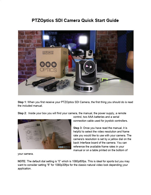
PTZOptics SDI Camera Quick Start GuideStep 1:When you first receive your PTZOptics SDI Camera, the first thing you should do is read the included manual.Step 2: Inside your box you will find your camera, the manual, the power supply, a remotecontrol, two AAA batteries and a serialconnection cable used for joystick controllers.Step 3:Once you have read the manual, it ishelpful to select the video resolution and framerate you would like to use with your camera. Thecamera's resolution is set by a yellow dial on theback Interface board of the camera. You canreference the available frame rates in yourmanual or on a table printed on the bottom of your camera.NOTE:The default dial setting is “0” which is 1080p60fps. This is ideal for sports but you may want to consider setting “6” for 1080p30fps for the classic natural video look depending your application.Step 4:Once you have set your resolution dial, can turn on your PTZOptics camera. If your network switch provides PoE (Power over Ethernet), you will not need to use the included power supply.NOTE:Only PTZOptics SDI and NDIcameras support PoE power. Thesecameras support PoE 802.3af. The cameravia PoE consume between 12 - 13 Watts;but at longer cable runs can require up to 15Watts to accommodate for voltage drop.Step 5: W hen you are first getting setup it ishelpful to connect your camera to an HDMImonitor, but you can also use the SDI output to view video from your camera as well.Step 6:Once your camera is powered on and connected to the network you should determine whether you will use a dynamic or static IP address. Each camera can have an IP address on your network which is used to control the camera with your computer, smartphone or IP connected joystick controller. This IP address is also used to stream video over your network and much more. We highly suggest assigning your camera a static IP address for long term use.Note:A dynamic IP address can change periodicallymaking it difficult to manage in the longer term. Wesuggest setting up static ip addresses with sequentialIP addresses for tidy management of multiplecameras.NOTE:For most networks in order to connect to thecamera you must be in the same subnet of the LAN (example – 192.168.1.123 & 192.168.1.111 belong to the same subnet; 192.168.1.123 &192.168.0.125 do not).Step7:Let’s put the included AAA batteriesinside our remote control and take a look at thefeatures. You can pan, tilt and zoom yourcamera using the up/down/left/right arrow keyson your remote. You can also, set a specificPTZ camera preset by clicking the “preset”button and than entering the number you wantto set. You can try moving the camera andcalling a preset quickly to test out the cameras movement operations. If you find the default camera preset movements too fast, you can alwayschange the speed settings in the camera menu. You can access the OSD Menu which stands for (On Screen Display) for this camera by pressing the “menu” button. This is where you can navigate into the advanced features such as iris, shutter speed, gain, color balance, contrast, luminance and much more with the arrow keys.Tip: Y ou can access the OSD menu remotely using the cameras IP address in any web browser or with the IP joystick.Tip:You can control up to 4 cameras with a single IR remote control. Use the shortcut *# and the corresponding Function key to set up unique camera IDs on your IR remote. Example *#F2 would set a camera to ID 2 on your IR remote.Step 8:You can use DHCP to dynamically assign an IP address for your camera. This is a great way to temporarily assign an IP address to your camera. You can setup your camera with DHCP by using the IR Remote and entering “#> *> 4”. Once the camera reboots, you can use the IR remote to locate the dynamic IP address by pressing “*> #> 4”.Step 9:You can assign a static IP addressto your camera using our Windows Only IPaddress settings tool, or with any Mac or PCcomputers web browser. Let’s use a webbrowser. Enter the IP address of yourcamera into your web-browser and pressenter. when prompted enter the defaultusername and password which is “admin /admin”. You may want to consider changing this default password in the admin area.Step 10: Navigate to the “Network” tab and choose “Fixed IP Address” from the very first drop down menu. You can now enter the static IP address you wish the camera to use and press “Apply.” You can now reboot your camera by clicking the “System” tab and clicking the “Reboot” button.Step 11: Now that your camera is all setup on the network consider downloading the free PTZ camera applications available at h ttp:///apps. You can quickly tweak your camera's settings and color match multiple cameras with advanced settings. The new apps available for both Mac and PC. When you first open the PTZOptics Control App you should click the “Settings Tab” to enter your camera's name and IP Address. Once you have done this you can click the camera name to select this camera. This application features multiple views available in the view dropdown menu. Click the “advanced tab” to access controls such as Shutter Speed, Iris, Brightness, luminance and much more. Finally, you can view your camera by clicking the Window dropdown menu and clicking the “Preview Window” selection. You can make this preview window full screen or snap the preview window to the controls. Now you can view the cameras video from anywhere on your local area network. You can choose from Stream 1 or Stream 2 (Stream 1 being HD and Stream 2 being SD and which is used for low bandwidth environments). Let’s snap the video stream to the rest of our video controls.Step 12:Before we leave this tool, let’s setup a couple PTZ presets. This can be done by clicking the “Preset” radio button and entering in the name you would like to give your preset. Once you have done this you can click any of the 9 buttons available and your preset will besaved. You will notice that the program automatically enters “recall” mode. When you are in recall mode, clicking these preset buttons will recall your saved pan, tilt and zoom presets.Step 13: L et’s connect to the RTSP video stream from our camera with Open Broadcaster Software also known as OBS. The follow steps will be very similar in video production software such as vMix, Wirecast or xSplit. Open OBS and add a Scene. In this scene we can add a source with the plus button in the area right next to scenes. Select “Media Source” and name the input. In the Properties of this media source we will uncheck the first two boxes: Local File and Restart Playback when source becomes active. Now we simply need to enter our RTSP information into the input text field which is the following“RTSP://YOUR-CAMERA-IP-ADDRESS/1”. The last “Slash 1 or Slash 2” represents the two available RTSP streams you can pull from each camera. Stream 1 is your High Definition Stream and Stream 2 is your standard definition stream.Step 14:To add audio into our RTSP stream we will use a Rode Microphone with a line level output and plug it into the 3.5mm audio input on the back of our camera. The 3.5mm audio input will provide audio embedded into our IP stream and HDMI output.Step 15:You can configure your cameras RTSP Settings in the Video Tab of the network interface. You have the ability to tweak your cameras RTSP settings to deliver reliable high quality video over IP. Let’s quickly review our recommended settings used for streaming RTSP video over your network.Resolution Frame Rate Bitrate Encoding Protocol 1080p 60fps 12288 h.2641080p 30fps 8192 h.264720p 60fps 6144 h.264NOTE:PTZOptics cameras also support MJPEG and H.265 HEVC encode protocols. If you would like to customize your RTSP Settings we highly recommend reviewing our “PTZOptics Streaming Settings Guide” available at /downloads.Step 16:You camera is now setup and your have learned how to access the cameras video over IP. Your cameras can also output high definition video through SDI and HDMI simultaneously to fulfill even more advanced video production workflows. Consider joining our PTZOptics User Group at /groups/ptzopticspals and if you have any follow up questions do not hesitate to reach out. If you encounter any issues during this setup process feel free to submit a support ticket at or simply call the phone number listed on our website. Enjoy!。
SDI仪表使用方法

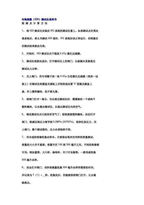
一、SDI污染指数测定仪污染指数(SDI)测定仪说明书:1、将SDI测试仪安装在RO系统的测试位置上。
如果测试点在预处理系统后,那么当测试SDI值时,RO系统应该正常运行,否则最后的测试结果就会无效。
2、开始时,SDI测试仪内不能放0.45μ微孔过滤膜。
3、测试仪连接完成后,打开测试仪上的阀门,让被测水直接流过测试仪几分钟。
4、关上阀门,用专用镊子放一张0.45μ白色微孔过滤膜(亮的一边朝上)在测试仪的膜盒支撑板上并轻轻地压紧“0”型圈及膜盒上盖,拧上塑料螺丝,但不要太紧。
5、将阀门打开一部分,当水流过测试仪时,慢慢旋松一个或两个塑料螺丝,让水漫出测试仪,以逐出测试仪内的空气。
6、确定测试仪内已经没有空气了,轻轻旋紧塑料螺丝。
完全打开阀门,将减压阀压力调节到0.2MPa(207KPa),保持住该压力,关上阀门。
整个测试期间,压力必须保持不变。
7、用合适的容器收集水样本。
只要保证每次用同样的容量测试,容量的大小并不重要。
容量可在100到500毫升之间。
不同的容器都可用:例如量筒、大口杯、咖啡杯、可口可乐瓶等。
一般考虑收集500毫升水样。
8、完全打开阀门,用秒表测量收集500毫升水样所需要的时间,并记录为T(1)=__秒。
收集完后,仍继续保持阀门打开,让水继续流出。
9、过5分钟后再用秒表测量收集另一个500毫升水样所需要的时间并记录为T(5)=__秒,过10及15分钟后各做一遍同样的测试并分别记录为T(10)和T(15)。
检测结束后,SDI值就能被计算出来。
有些水样数据采样可能要求延续到T(20),T(30)甚至T(60),当然这种水样是极少数的。
10、测定水温。
在整个测试期间,水温必须保持一致。
11、SDI值由下列公式计算得出:SDI=100P30/ Tt =100(1-T1/ T2)/ TtP30 -----在207kpa进水压力下的堵塞指数;Tt总的测试时间(分)通常为T15,此时P30<75%,不然测试T10或T5,使此时的P30<75%T1 -----初始时收集500ml水样所需的时间(秒);T2 -----经T1(通常为T15,即15分钟)后收集500ml 水样所需的时间(秒)。
SDI-HDMI双向转换器用户手册

SDI HDMI 双向转换器用户手册在使用本产品时,请仔细阅读本用户手册说明妥善保管好本用户手册,以便日后查阅由于产品的不断更新,产品技术参数变化恕不另行通知概述SDI HDMI双向互转广播级转换器是一款将高清数字分量串行接口SDI信号转换为HDMI信号,以及将HDMI信号转换为高清数字分量串行接口SDI信号的设备。
可自适应SD、HD、3Gb/s等视频格式。
无论您需要SDI与HDMI信号间的相互转换,或是SDI视频信号分配均可满足你的需要.本设备可广泛应用于视频会议系统,多媒体信号广播、广播电视节目制作与传播、SDI/HDMI信号延伸和视频安防监控领域。
特点●支持1路SDI输入,2路SDI输出,1路HDMI输入及输出。
支持 SMPTE 424M, SMPTE 292M, SMPTE 259M标准。
● SD/HD/3G-SDI信号均可完美转换。
●采用自适应信号增强技术,同时确保视频信号无损还原。
●支持5V-24V宽幅电压输入。
●灵活的供电系统,适配器供电或者背扣电池供电。
●便携式设计方便工程项目使用。
●两侧标准1/4孔安装。
●电源/输入/输出状态指示灯。
●压铸工艺铝合金外壳,坚固耐用。
●背扣式电池供电,可在郊外无市电情况下使用. 面板与端口简介①电源输入端口② LED切换模式状态指示灯③ HDMI 输入端口④ HDMI输出端口⑤ MODE ∨转换模式切换键(往下循环切换)⑥ SDI 输出端口1⑦ SDI输出端口2⑧ SDI输入端口⑨ MODE ∧转换模式切换键(向上循环切换)⑩ F970电池扣板(当安装上电池后,将扣板的尾巴线DC插头插入设备上的DC插座,向设备供电)切换模式说明按MODE键(两个MODE键作用相同, MODE ∨向下循环切换, MODE ∧向上循环切换)对信号转换模式进行切换,状态指示灯LED相应改变颜色1.指示灯红色: HDMI信号环路输出 ,SDI视频信号二路分配输出2.指示灯绿色: 将S DI信号转换为HDMI信号输出,HDMI信号转换为S DI信号,并分配为2路输出。
污染指数(SDI)测试仪说明书
污染指数(SDI)测试仪说明书检测及计算方法1、将SDI测试仪安装在RO系统的测试位置上。
如果测试点在预处理系统后,那么当测试SDI值时,RO系统应该正常运行,否则最后的测试结果就会无效。
2、开始时,SDI测试仪内不能放0.45μ微孔过滤膜。
3、测试仪连接完成后,打开测试仪上的阀门,让被测水直接流过测试仪几分钟。
4、关上阀门,用专用镊子放一张0.45μ白色微孔过滤膜(亮的一边朝上)在测试仪的膜盒支撑板上并轻轻地压紧“0”型圈及膜盒上盖,拧上塑料螺丝,但不要太紧。
5、将阀门打开一部分,当水流过测试仪时,慢慢旋松一个或两个塑料螺丝,让水漫出测试仪,以逐出测试仪内的空气。
6、确定测试仪内已经没有空气了,轻轻旋紧塑料螺丝。
完全打开阀门,将减压阀压力调节到0.2MPa (207KPa),保持住该压力,关上阀门。
整个测试期间,压力必须保持不变。
7、用合适的容器收集水样本。
只要保证每次用同样的容量测试,容量的大小并不重要。
容量可在100到500毫升之间。
不同的容器都可用:例如量筒、大口杯、咖啡杯、可口可乐瓶等。
一般考虑收集500毫升水样。
8、完全打开阀门,用秒表测量收集500毫升水样所需要的时间,并记录为T(1)=__秒。
收集完后,仍继续保持阀门打开,让水继续流出。
9、过5分钟后再用秒表测量收集另一个500毫升水样所需要的时间并记录为T(5)=__秒,过10及15分钟后各做一遍同样的测试并分别记录为T(10)和T(15)。
检测结束后,SDI值就能被计算出来。
有些水样数据采样可能要求延续到T(20),T(30)甚至T (60),当然这种水样是极少数的。
10、测定水温。
在整个测试期间,水温必须保持一致。
11、SDI值由下列公式计算得出:SDI=100P30/ T t =100(1-T1/ T2)/ T tP30-在207kpa进水压力下的堵塞指数;Tt总的测试时间(分)通常为T15,此时P30<75%,不然测试T10或T5,使此时的P30<75%T1-初始时收集500ml水样所需的时间(秒);T2-经T1(通常为T15,即15分钟)后收集500ml 水样所需的时间(秒)。
SDI污染指数自动测定仪产品说明书
∙SDI污染指数自动测定仪产品说明书∙1、监测RO(反渗透)系统进水的污染趋势一直都是一项必不可少的工作。
通常,只有当RO膜需要清洗时,人们才会意识到污染问题的存在,但是这已经造成了损失严重的停机事件,还有更严重的后果就是需要更换十分昂贵的膜。
工业中已经采用了几种方法来测量进水的污染趋势,例如:浊度、颗粒计数和污染指数(SDI)测量等等。
由于浊度和颗粒计数测量的工作方法是采用光学原理,对于不感光的胶体和微粒则无法检测,因此并不能直接测量悬浮液中微粒造成的污染即对膜的“淤塞能力”,用它们来判断污染趋势是非常困难的。
而SDI监测方法直接测量污染趋势,ASTM D4189-95中规定SDI测量方法是测定在一定压力和标准间隔时间内,一定体积的水样通过微孔过滤器(0.45μm)的阻塞率。
通常,RO(反渗透)系统在进口原水的SDI值小于1的情况下操作数年都没有问题;若在原水SDI值小于3情况下操作,则数月无需清洗膜。
然而,在原水SDI值为3~5下操作的系统,则要经常清洗膜,这样的系统通常不能正常工作。
SDI值大于5的原水,根本不能用于RO的进水。
因此,准确而及时地监测RO进水的SDI是非常必要的。
然而,人工SDI测量是一种既乏味又耗时的工作。
该SDI污染指数自动测定仪可以自动、连续地监测RO进水的污染指数。
操作者能够快速地、准确地检测反渗透预处理系统的效果,从而使SDI污染指数检测不再烦琐、最大程度地减少人工监测的误差。
SDI 使用了ASTM D4189-95里说明的标准测试方法,以每5、10和15分钟的间隔来计算SDI。
对像井水、过滤水和澄清过的低浊度(<1.0NTU)的水也能精确测定。
SDI的计算公式如下:SDIn =(1-t0/tn)×100/nSDI 污染指数(样水压力30psi,测试过程温差不超过1°C的条件下)n 测试(膜过滤样水)时间,一般取第5、10、15分钟t0 测试开始时(即n=0时),过滤得到一定体积样水所需的时间tn 测试开始n分钟后(膜过滤第n分钟),过滤得到上述相同体积样水所需的时间2、技术特性2.1、主机参数1. 电源: 200-240 VAC,50-60Hz,1.0Amps2. 整机功率: 30W( max )3. 使用环境温度: 5~45℃4. 使用环境湿度: 10~95% RH(无凝结水)5. 重量: < 4Kg6. 样品条件: 35到100psi,5~45℃,最小流量1000 ml/min1. 外形尺寸:主机255×300×125mm2. 连接:进水1/4″外丝出水 10mm塑料管3.1、标准配置①主机 1套②取样软管及转换接头 1米,1套③微孔滤器(含O型密封圈) 1套④排水软管 1米⑤与主机相连的电源线及电源插头(三眼) 1.5米⑥壁式安装挂板套件 4组⑦减压器1套3.2、可选配件a 水平仪固定安装调试时需要b 水平三角架移动使用时需要c 取样快速接头移动使用时需要1、仪器安装SDI适合于在线安装和使用,也可以移动使用,用户可以根据使用方式来选择安装方式。
- 1、下载文档前请自行甄别文档内容的完整性,平台不提供额外的编辑、内容补充、找答案等附加服务。
- 2、"仅部分预览"的文档,不可在线预览部分如存在完整性等问题,可反馈申请退款(可完整预览的文档不适用该条件!)。
- 3、如文档侵犯您的权益,请联系客服反馈,我们会尽快为您处理(人工客服工作时间:9:00-18:30)。
SDI-CPT中文操作手册目录1 SDI-CPT系统描述 (2)2 SDI-CPT硬件连接 (2)2.1 GPS天线安装 (2)2.2 SDI-CPT安装 (3)2.3 电气连接 (3)2.4 电源连接 (5)3 系统工作 (5)3.1 工作顺序 (5)3.2 系统启动和对准技术 (6)3.2.1 默认动态对准 (7)3.2.2 粗对准 (8)3.2.3 手动对准 (8)3.3 配置SDI-CPT (8)3.3.1 端口配置 (8)3.3.2 输出语句配置 (8)3.3.3 命令配置 (9)3.3.4 CDU软件配置 (9)3.4 导航模式 (21)3.5 载体与SDI-CPT间安装角度偏差校准过程 (21)3.6 退出系统 (22)4 数据协议 (22)5 项目操作建议 (30)1 SDI-CPT系统描述SDI-CPT的操作主要包括硬件连接、GPS天线安装、SDI-CPT安装和设备配置等几部分。
SDI-CPT是GPS/INS组合导航产品,内部有三个陀螺、三个加速度计和NovAtel OEMV3接收机,采用GPS和IMU紧耦合技术,提供比纯GPS导航或纯惯性导航系统更高精度的三维位置、速度和姿态信息。
2 SDI-CPT硬件连接SDI-CPT硬件连接主要涉及GPS天线、电源,外部数据记录设备与SDI-CPT 的连接,具体如下图说示:图 2-1 SDI-CPT硬件连接示意图其中:1 代表SDI-CPT2 代表GPS天线3 代表电源,电压为+9~+18VDC(此处已转接28V-12V稳压电源模块)4 代表数据记录设备,如PC机,工控机等,可以通过COM1口或COM2口连接2.1 GPS天线安装为了得到精确的定位信息,确保GPS天线稳固地安装在载体上,且对空视线良好,没有遮挡,并尽可能减小多路径干扰。
2.2 SDI-CPT安装将SDI-CPT牢固地安装在载体上,且确保SDI-CPT与GPS天线相位中心的距离恒定,同时保证SDI-CPT方向相对于载体和天线也是恒定。
为了方便使用,SDI-CPT应按照如下方式安装:Z轴指向上且Y轴通过载体前端指向前,与载体前进方向一致,如图2所示:图2-2 SDI-CPT安装图注意:SDI-CPT与天线之间的位置关系在载体运动过程始终保持恒定;在封装坐标系中测量从SDI-CPT导航中心到GPS天线相位中心的偏移量。
天线距离SDI-CPT越近,位置解算精度越高。
另外使用SETIMUTOANTOFFSET 命令输入的测量值须尽可能精确,或至少比使用的GPS位置精度高。
例如,天线偏差10cm误差会导致至少10cm误差输出。
毫米级精度最好,可以使用全站仪精确测量偏移量。
如对GPS、IMU相对位置不敏感,可不输入,则得到的位置为GPS 天线位置。
2.3 电气连接SDI-CPT有一个多功能的I/O接口,包括RS232通讯口、USB口,秒脉冲信号和事件输入信号等。
具体针脚定义如下:表2-1 SDI-CPT接头针脚定义SDI-CPT有两个串行DB9接口,其中COM2是RS232接口,为DB9针头;COM1是RS232或RS422接口可选,为DB9针孔,将针脚7和8短接则COM1 口为RS422接口,否则为RS232接口;SDI-CPT还有一个USB口和CAN口。
连接时,可用SDI-CPT的USB口与电脑的USB口连接;或用SDI-CPT的COM2口与电脑串口连接。
2.4 电源连接SDI-CPT的供电电压范围为+9~+18VDC,功耗最大为15W,其内部有个电源模块进行以下工作:l对供电电压进行滤波和校准;l对过压、过流和高温情况进行保护;l提供自动复位电路保护注意:给SDI-CPT供电的电源在上电过程中必须是不变的,以确保内部逻辑电路合理地初始化并进入有效工作状态。
如果上电过程中供电有变化,则IMU 中加速度状态字会显示失败且在RAWIMUS记录中加速度计测量为零。
注意:供电时注意电源正负极性,以免将产品烧坏。
注意:SDI-CPT接上电缆后所有地信号共地,包括电源地、信号地和外壳地。
3 系统工作3.1 工作顺序a)SDI-CPT和GPS天线安装;b)SDI-CPT导航中心到GPS天线相位中心偏移量的测量;c)通讯电缆连接,用USB口或串口与电脑连接;d)GPS天线电缆连接;e)SDI-CPT供电;f)系统启动;g)进行初始对准,并配置SDI-CPT;h)导航;i)退出系统。
3.2 系统启动和对准技术系统需要初始姿态估计启动导航滤波器,即所谓的系统对准。
一上电,系统没有位置、速度和姿态信息。
系统第一次上电时,按照以下事件发生:a)跟踪第一颗卫星并解算粗时间;b)跟踪足够多卫星计算位置信息;c)解算出精确时间,以开始给IMU测量定时;d)原始IMU测量开始被接收机同步且INS滤波器可用,同时RAWIMU log可用。
此时INS状态字为INS_INACTIVE;e)惯性对准程序启动且INS状态字为INS_ALIGNING;此时有三种方法用于完成对准,具体见以下描述;f)对准完成且INS状态字变成INS_ALIGNMENT_COMPLETE;系统转入导航模式,此时得到GPS/INS解算。
g)利用GPS更新精确解算。
一旦系统姿态角标准偏差小于2°且载机经过一些运动后,INS状态字变成INS_SOLUTION_GOOD。
如果航向标准偏差增加大于2°,状态字变成INS_SOLUTION_NOTGOOD。
表3-1 INS状态字二进制ASCII 描述0 INS_INACTIVE IMU记录出现,但对准程序未开始,INS不起作用1 INS_ALIGNING INS处于对准模式。
在此状态,用户可运动以初始化动态对准或发送SETINITAZIMUTH命令。
2 INS_SOLUTION_NOT_GOOD INS解算仍在计算但航向解算误差大于2°。
解算仍然有效但应监控解算误差。
在没有GPS信号时会遇到此状态。
3 INS_SOLUTION_GOOD INS处于导航模式且INS解算良好6 INS_BAD_GPS_AGREEMENT INS处于导航模式且GPS解算错误。
可能是由于多路径效应或有限可见卫星。
惯性滤波器拒绝GPS位置且等待解算质量提高。
7 INS_ALIGNMENT_COMPLETE INS处于导航模式但载体没有足够运动3.2.1 默认动态对准SDI-CPT默认对准方法为快速或动态对准。
如果系统按照建议安装方式安装,即Z轴指向上且Y轴与载体前向一致,那么不需要额外配置来完成运动对准。
一旦INS状态字变成“INS_ALIGNING”,运动对准开始,一旦载体速度达到1.15m/s(~4km/h),INS状态字会变成“INS_ALIGNMENT_COMPLETE”。
运动对准把GPS对地航迹俯仰角和航向角转变成IMU姿态角。
此对准方法最适用于地面运动,因为载体地面运动方向与载体前轴一致,且载体横滚角接近于零。
推荐在地面完成初始对准后再进行飞行等载体运动。
如果SDI-CPT按照建议安装方式安装,即Z轴指向上且Y轴与载体前向一致,那么不需要额外配置来完成运动对准。
如果SDI-CPT安装时IMU与载体轴向不一致,需要额外配置完成运动对准。
可以使用CDU软件或以下命令进行配置:a)用SETIMUORIENTATION命令设定与重力方向最一致的IMU轴向。
例如,如果SDI-CPT的Z轴指向上,则命令如下:SETIMUORIENTATION 5表3-2 IMU轴向定义ASCII值二进制值描述0 0 粗对准中IMU自动确定轴向(默认)1 1 X轴指向上2 2 X轴指向下3 3 Y轴指向上4 4 Y轴指向下5 5 Z轴指向上6 6 Z轴指向下b)用VEHICLEBODYROTATION命令设定从载体坐标系到SDI-CPT坐标系的角度偏差,见P68。
例如,假设IMU安装时Y轴指向载体右端而不是前端,则命令如下:VEHICLEBODYROTATION 0 0 -90快速对准中初始姿态精度取决于载体运动和用VEHICLEBODYROTATION命令输入的角度精度。
对准只是载体姿态的估计,随着载体运动,姿态解算精度会提高。
一旦姿态精度汇聚,INS状态会变成INS_SOLUTION_GOOD。
3.2.2 粗对准粗对准使用加速度计和陀螺仪的平均值估计IMU的姿态。
一旦INS状态字变成“INS_ALIGNING”,粗对准开始,要求载体保持静止约60秒。
载体保持静止最少时间为5秒,但粗对准的质量会很差。
为了执行粗对准,为了执行粗对准,必须用SETINITAZIMUTH命令输入载体初始航向估计。
假如IMU Y轴指向东,标准偏差在10度之内,则命令如下:SETINITAZIMUTH 90 10初始姿态精度取决于计算横滚和俯仰角保持静止的时间和用SETINITAZIMUTH命令输入的航向标准偏差。
为了使SDI-CPT达到最优性能,输入航向标准偏差必须与输入航向真实质量匹配。
如果不能确定输入航向质量,最好使用更大标准偏差。
对准只是载体姿态的估计,随着载体运动,姿态解算精度会提高。
一旦姿态精度汇聚,INS状态会变成INS_SOLUTION_GOOD。
3.2.3 手动对准如果已知载体姿态角,用户可使用SETINITATTITUDE命令手动输入姿态信息,命令如下:SETINITATTITUDE pitch roll azimuth pitchSTD rollSTD azSTD3.3 配置SDI-CPT3.3.1 端口配置设置端口通讯参数命令:COM [port] bps[parity[databits[stopbits[handshake[echo[break]]]]]] 假设SDI-CPT的COM1口与电脑连接,通讯波特率为115200bps,则命令如下:com com1 115200设置完成后,查看端口配置命令:log comconfig3.3.2 输出语句配置从COM1口以50Hz速率连续输出载体的位置、速度和姿态信息,命令如下:log com1 inspvab ontime 0.02设置完成后,查看端口输出语句命令:log loglist3.3.3 命令配置a)配置当前端口波特率com com1 115200b)精确输入IMU导航中心到天线相位中心之间的偏差,在SDI-CPT封装坐标系描述setimutoantoffset x_offset y_offset z_offset [x_stdev] [y_stdev] [z_stdev]c)采用动态对准方法,如果SDI-CPT按照建议安装方式安装,不需要额外配置,否则需要输入以下命令:SETIMUORIENTATION 5VEHICLEBODYR OTA TION alpha beta gamma [σ alpha] [σ beta] [σ gamma]d)采用粗对准方式,必须输入载体初始航向估计SETINITAZIMUTH azimuth azSTDe)采用手动对准方式,须输入载体初始姿态信息SETINITATTITUDE pitch roll azimuth pitchSTD rollSTD azSTDf)记录载体位置、速度和姿态信息log inspvab ontime 0.01log bestposb ontime 1log bestvelb ontime 1g)保存配置saveconfig3.3.4 CDU软件配置一旦SDI-CPT硬件连接完成,产品上电,启动CDU软件进行通讯。