PM700中文操作手册
施耐德电气PM800-PM700-PM200-DM6000-PM1000仪表应用比较

DO),PM8M2222(2DO)
DO),PM8M2222(2DO)
电能脉冲输 出模拟量输出 (AO) 波形捕捉及 负荷趋势预 测电压的下陷 和骤升监测 报警记录
无 选配PM8M2222模块实现 AO功能扩展(2AO)
无
无 无
无 选配PM8M2222模块实现 AO功能扩展(2AO)
无
无 有报警记录,带时钟
答:仪表的DO输出功能为无源继电器接点输出。主要有2类用户:1) 在400V系统中,当对应电气间隔断路器为框架式断路器或者配置了电 动操作机构的塑壳断路器时,用仪表的DO输出来实现对断路器的分闸 与合闸操作,这种情况下,DO的数量为2个配置;2)当现场需要对某 个电气参数的越限告警采用继电器输出时,配置DO输出。例如:电压 值超过设定值,则告警,并有继电器接点信号输出用于驱动报警音响 或者其他智能设备用。
数据统计
、需量统计(电流、电压、 、需量统计(电流、电压、 值、需量统计(电流、电 、需量统计(电流、电压、 量统计(电流、电压、有功 需量统计(电流、电压、 量统计(电流、电压、有功 量统计(电流、电压、有功 有功功率、无功功率、视在 有功功率、无功功率、视在 压、有功功率、无功功率 有功功率、无功功率、视在 功率、无功功率、视在功 有功功率、无功功率、视 功率、无功功率、视在功 功率、无功功率、视在功
无
无
总有功电度统计、总无功 电度统计、总视在电度统
计
电流不平衡度和电压不平衡 度
电流不平衡度和电压不平衡 度
电流不平衡度和电压不平 衡度,电流电压总谐波畸 变率
无
无
电流需量和最大值统计, 电压需量和最大值统计
PM1200 相电流及中性线电流;相电 压及平均相电压;线电压及 平均线电压;频率;相有功 功率及总有功功率;相无功 功率及总无功功率;相视在 功率及总视在功率;相功率 因数及平均功率因数; 总有功电度统计、总无功电 度统计、总视在电度统计
(完整)PM操作手册

nGenius系统操作手册NetScout公司目录1.1Java插件 (1)1。
2PM客户端 (2)1.2。
1安装PM客户端 (3)1。
2。
2采用PM客户端登录PM (6)2配置PM服务器 (6)2.1设备管理 (7)2.2全局配置 (8)2.2.1增加单一端口协议 (9)2。
2.2增加多端口协议 (10)2。
2。
3增加基于服务器地址的协议 (10)2。
2。
4增加基于URL的协议 (11)2.2.5启用P2P协议检测 (12)2.3模板 (13)2.4监控组 (14)2.5配置服务器 (15)2.6用户帐户 (16)3网络流量监控 (18)3.1监控链路层信息 (18)3.2监控网络层信息 (19)3。
3监控应用层信息 (20)3.3.1查看某特定应用协议的曲线图.......... 错误!未定义书签。
3.4监控特定主机信息 (21)3。
7数据包捕获分析 (22)4配置并查看报表 (22)4.1Ad Hoc报表 (23)4。
2News Paper报表 (23)4。
2。
1采用Newseditor定制报表 (23)4.2.2查看报表 (25)5常用功能的配置及实现方法 (26)5。
1监控响应时间 (26)5.1.1被动测量的配置步骤 (26)5.1.2查看应用响应时间 (30)5。
2子网监控(Site Monitor) (34)5.2.1在探针的相应接口启用Site功能 (34)5.2。
2定义Site (35)5。
2.3绑定Site并修改Site接口速率 (36)5.2。
4监控Site (37)5.3配置netlfow (38)5。
3.1路由器/交换机的配置 (38)5.3.2配置探针采集 NetFlow (39)5.3.3关闭探针的 NetFlow (40)6备份和恢复 (40)7常见问题 (41)7.1如何更改PM的IP地址 (41)7.4如何停止PM内置的TFTP服务 (41)7.5如何升级探针Firmware (42)7.6如何复制数据库文件到另一台PM (43)1登录PM登录PM服务器可以采取二种方式:•Java插件•PM客户端首先通过IE联接到PM服务器,输入http://PM地址:端口号,在WEB界面的左上角可看到下载界面,有二种选择:Java Plugin、PM Client Install1.1 Java插件点击“Java Plugin”,可看到下载界面,如下图根据客户端的操作系统,选择相应的Java Plugin,如选择windows的Java插件,会出现提示下载Java文件的提示,如下图可保存到系统中进行安装,也可直接打开进行安装。
PM详细注册教程与操作

1、PM简介2、注册向导3、登录账号(为了安全,首次登录账户要设置“密码卡”保护)4、如何充值(用国内网银中的人民币直接给账户充值美元)5、如何提现(把账户中美元提现人民币到国内网银)6、如何转账(把账户中美元转给另一PM账号)7、如何用PM网银投资(投资基金多用PM或者LR)一、PM简介:perfectmoney简称PM,类似于PayPal(PP),AlertPay(AP),LibertyReserve(LR),也是一种国际网银,可以用来交易美元(USD)、欧元(EURO)等国际货币。
PM与其他网银比较,优势有三:1、与其他网银不同的是,PM可以直接和国内的银行卡相连,也就是说可以直接用银行卡充值到PM里面(冲钱和提现都是根据当天的汇率自动转换的)。
比如,你往PM里面充值10美元,可以选择使用银行卡网银充值,大概10美元是69.4人民币(根据当时汇率而定)。
当然PM里面的美元、欧元也可以直接提现到银行卡里面,十分方便快捷。
比如你提现100美元,自动到你银行卡700左右人民币(根据当时汇率而定)。
这就省去了很多麻烦,既免去了找人兑换美元的麻烦,也免去了找人兑换被骗的风险。
2、PM最大的优点是,跟银行一样,往PM里面存钱,可以获得利息,年利息高达7%。
这是一个多么庞大的利息,就算不投资,直接往PM里面存10000美元,那么一年的利息就是700美元,相当于5000人民币,这是一个多么好的存钱方法。
而且,PM交易所收取的手续费也十分低,相比LR和PP来说,低了很多。
所以日日发网团队今日重点推荐大家使用PM进行各类投资。
3、更为重要的是,PM支持多个国家的语言,当然包括中文。
所以注册页面是中文的,就算不懂英文的朋友也能轻易操作。
几种网银比较:1、PP和AP都需要认证,不认证只能收款不能转账。
而且收取美元后还要找别人兑换成人民币,有被骗的风险;(如果你有双币种的银行卡,也可以直接把PP和AP中的美元提现到国内银行卡里面,但手续费很高)2、LR不需要认证,目前可以通过【广东电子黄金采购站】或【黄金网币兑换中心】,以及【巾帼网币兑换】等许多网上诚信中介把LR中的美元兑换成人民币,支持支付宝以及工商、农业、建设银行等,很方便(兑换只需0~2小时工作时间);3、PM不仅不需要认证,而且直接可以与国内银行卡相连,直接把LR中的美元提现到国内银行卡里面,十分方便快捷。
施耐德产品简单介绍(电-表)

典型应用 电力监测:对系统内部的线路和负载进行远程的实时监测 能源管理:满足客户对电能分项计量和成本分摊的特殊需求 系统维护:实时报警和存储,快速排除故障 遥信遥控 标配四个数字输入端,采集开关多种状态 两个继电器输出端,实现对断路器的遥控功能 国际标准 电能精度0.5S级,符合IEC 62053-22电能计量 精度要求 仪表满足IEC 61557-12的全性能标准(IEC 61557-11 PMD/S/K70/0.5) 电能质量分析 测量系统的总谐波畸变率(THD和TDD) 提供带有时间标记的峰值需量计算,负荷预测 事件告警:配置30种报警类型,对过压、欠压和三相不平衡等常见故障及时报警,并对最近的40次
施耐德电气 Schneider
施耐德电能管理和电能质量产品简单介 绍
电能管理软件
StruxureWare™ Power Monitoring Expert 电能管理 软件作为一套完整的系统方案,通过管理实时电能状 态和能源使用效率,实现投资回报。同时呈现关键信 息,在保证可靠供电的前提下,减少能源和维护成本。 其丰富的电能质量分析功能,更加全面的提升能源管 理水平。
PM5350 电力参数测量仪表
PM5350 电力参数测量仪表,是施耐德电气PowerLogic 仪表家族中又一全新产品。其秉承北美设计 风格,外形设计精巧,功能强大,适用于各类行业的配电监测系统。PM5350 仪表可对用电负荷的 全电力参数实时监测,并且为客户提供中英文显示,LCD 超大屏幕,在强光和大视角环境下都能获 得良好的视觉效果。
StruxureWare™ Power SCADA Expert 电力监控软件 为用户提供一个高可靠性、高实时性的分布式电力监 控方案。专为工业应用领域、基础设施和大型建筑的 配电网络电力监控管理而设计。帮客户高效和安全地 进行配电操作和保证设备可靠运行。
PM项目管理系统操作说明书模板

信息化建设项目PM项目管理系统操作说明书文档编号:PM-001作者:信息化小组版本:V1.0创建日期:2013 年9月10日文档说明此文档说明适用于《建筑云PM项目系统操作说明书》。
文档类别此文档属于项目实施的重要过程文档,是系统管理员日常工作的必要参考和重要依据。
编写目的为系统操作人员的日常工作提供必要的支持和帮助,从而确保系统能够平稳运行,并且帮助系统操作人员更加快速有效地解决系统运行过程中出现的问题。
使用方法此文档甲方项目经理提供模板,双方项目经理结合客户的具体情况共同编辑完善,最后作为项目的成果保存给客户,并发放系统操作人员使用。
文档依据《系统运行管理制度》使用对象该文档使用人员包括:项目领导、项目组成员及其它项目相关人员;项目领导、项目组成员及其他项目相关人员;获得授权的第三方人员。
编制工具Microsoft Word 2010文档控制文档变更记录*A–增加M–编辑D–删节文档审核记录文档去向记录目录文档说明 (2)文档控制 (3)第一章系统概述 (7)1.1 产品介绍 (7)1.2 主要功能 (7)1.3 产品接口 (9)1.4 操作规程 (9)1.5 操作说明 (9)1.6 系统通用操作 (10)1.6.1 单击操作 (10)1.6.2 导航介绍 (10)1.6.3 添加操作 (10)1.6.4 编辑操作 (11)1.6.5 删除操作 (11)1.6.6 查询操作 (11)1.6.7 打印操作 (12)1.6.8 多附件上传操作 (13)1.6.9 导出操作 (15)第二章项目管理 (15)2.1 项目管理系统概述 (15)2.1.1 系统功能框架 (16)2.1.2 系统分层应用逻辑 (16)2.2 项目信息 (17)2.3(A)投标管理182.3.A1 系统概述 (18)2.3.A2 应用逻辑 (19)2.3.A3 主要功能 (20)2.3(B)招标管理 (22)2.3.B1 系统概述 (18)2.3.B2 应用逻辑 (19)2.3.B3 主要功能 (20)2.4 合同管理 (29)2.4.1 系统概述 (29)2.4.2 应用逻辑 (30)2.4.3 主要功能 (30)2.5 进度管理 (35)2.5.1 系统概述 (35)2.5.2 应用逻辑 (36)2.5.3 主要功能 (37)2.6 成本管理 (40)2.6.1 系统概述 (40)2.6.2 应用逻辑 (40)2.6.3 主要功能 (41)2.7 质量管理 (45)2.7.1 系统概述 (45)2.7.2 应用逻辑 (46)2.7.3 主要功能 (46)2.8 安全管理 (49)2.8.1 系统概述 (49)2.8.2 应用逻辑 (50)2.8.3 主要功能 (50)2.9 技术管理 (52)2.9.1 系统概述 (52)2.9.2 应用逻辑 (52)2.9.3 主要功能 (52)2.10 物资管理 (55)2.10.1 系统概述 (55)2.10.2 应用逻辑 (56)2.10.3 主要功能 (56)2.11 设备管理 (57)2.11.1 系统概述 (57)2.11.2 应用逻辑 (58)2.11.3 主要功能 (58)2.12 环境管理 (60)2.13 竣工管理 (60)2.13.1 系统概述 (60)2.13.2 应用逻辑 (61)2.13.3 主要功能 (61)2.14 相关方管理................................................................................... 错误!未定义书签。
PM800快速参考手册

三级菜单 菜单名称
显示内容 PEAK 峰值需用量 PF 峰值同步功率因数
INC1 第1个增量电能
INC2 第2个增量电能
INC3 第3个增量电能
1 A相真实功率因数 2 B相真实功率因数 3 C相真实功率因数 TOTAL 总真实功率因数 1 A相置换功率因数 2 B相置换功率因数 3 C相置换功率因数 TOTAL 总置换功率因数
D/T A A相峰值日期时间 A相峰值年月日、时间 D/T B B相峰值日期时间 B相峰值年月日、时间 D/T C C相峰值日期时间 C相峰值年月日、时间
1 A相有功功率 2 B相有功功率 3 C相有功功率 TOTAL 总有功功率 1 A相无功功率 2 B相无功功率 3 C相无功功率 TOTAL 总无功功率 1 A相视在功率 2 B相视在功率 3 C相视在功率 TOTAL 总视在功率 KWd 总需用有功功率 KWd 总需用有功功率 KWd 总需用有功功率 MIN 计算周期(分) LAST 上一周期需用量 PRED 预测需用量 PEAK 峰值需用量 PF 峰值同步功率因数 LAST 上一周期需用量 PRED 预测需用量 PEAK 峰值需用量 PF 峰值同步功率因数 LAST 上一周期需用量 PRED 预测需用量
THD I 电流谐波畸变率 U 线电压
V 相电压 I 电流
最小值、相位、日期时间 MIN 最小值
MAX 最大值
2次谐波分量
H2 2次谐波分量
H3 3次谐波分量
……
H13 13次谐波分量
2次谐波分量
H2 2次谐波分量
H3 3次谐波分量
……
H13 13次谐波分量
的切换通过最后一个按钮
实现,返回上级菜单通过第一个按钮
实现,进入下级菜单直接操作
PEAA700原子吸收光谱仪简明操作手册

PEAA700原子吸收光谱仪简明操作手册AANALYST 700/800原子吸收光谱仪简明操作手册(WINLAB32)张扬祖编PerkinElmer,Shanghai2004年3月目录1.火焰部分1.1开机1.2建立方法1.3装灯与点灯1.4点火1.5优化仪器条件1.6样品测定1.7熄火与关机2.石墨炉部分2.1开机2.2建立方法2.3更换石墨管及石墨管的老化处理2.4调节自动进样器位置2.5样品测定2.6关机3.数据处理3.1出报告3.2文件删除1.火焰部分1.1开机确认仪器主机和计算机已经接入到合适的电源,按照下列步骤开机:1.1.1开空气压缩机(将空气压缩机电源插头插入220伏电源插座上);1.1.2打开氩气钢瓶阀门,使其次级压力在350kpa;1.1.3开计算机显示屏和计算机主机开关,使其进入到WINDOWS 2000或WINDOWS XP界面;1.1.4待空气压力达到500kpa后,即可打开光谱仪主机开关;此时仪器对石墨炉自动进样器等进行自检;1.1.5待上述自检动作完成,听到两声清晰的”突”,”突”声后,用鼠标器点击AAWINLAB32快捷图标或通过链接式菜单命令进入(Start—Programm—Winlab32—Winlab32 Analyst),这时光谱仪对光栅,马达等机械部件进行自检,同时计算机屏幕上出现如下画面图1:图1. WINLAB32原子吸收操作启动画面1.1.6 稍过片刻,画面自动变成如图2所示;图2.Aanalyst700/800仪器自检画面画面中代表两个通讯状况的接头接上,同时颜色变绿,此时表明仪器通过自检,可以进入到正常使用状态,画面显示如图3.图3.AA仪器32位应用软件操作界面(火焰)1.2 建立方法1.2.1 用鼠标器点击下拉式菜单File→New→Method,此时屏幕上出现画面如图4所示:图4.方法建立开始条件选择1.2.2 用下列两种方法之一选择欲建立方法的元素:1.用鼠标器点击“Element”右边的箭头,再直接单击下拉式元素列表中的任何一个元素;2.在保持元素被涂蓝的情况下,输入目标元素的第一个字母,此时凡是以该字母打头的元素都排列在前面,图5显示的是以C为第一字母的元素排列:1.2.3 如若建立铜元素的测量方法,可用鼠标器点击元素符号”Cu”,此时出现画面如图6所示:图6.方法建立中光谱仪参数输入页面之一1.2.4 根据样品浓度及样品基体的组成复杂程度选择或设定波长,狭缝,信号测定类型,在进行火焰法原子吸收光谱测定时,测量方式总是”时间平均”.如果需要了解仪器的详细性能及测定时要注意的事项,可用鼠标器点击“Tools”菜单中的“Recommended conditions”命令,此时屏幕上将会出现画面如图7:图7.元素推荐条件1.2.5 在“Define Element”分页面中各项目的参数选定或设定完毕后,用鼠标器点击方法编辑画面右上方的“Setting”,软件进入到测量时间和灯参数设定画面,见图8:图8.读数及灯电流输入页面1.2.6 读数时间的设定主要考虑两个因素:噪声大小和样品量,典型的读数时间可设定为3-5秒; 读数延迟时间一般为2-3秒;灯电流以选择“灯设定窗口值”为好,特殊情况下也可选择“使用确定的灯电流值”.下一步进入到“Sample”页面如下图9:图9.方法编辑中的火焰状况页面1.2.7 燃气和助燃气的流量将从两个方面影响火焰:火焰的大小和火焰的氧化还原性.对于大多数常见元素来说,建议使用氧化性火焰.而对于象Cr,As,Sn等一些元素则需要使用富燃火焰.观察高度对于大多数元素来说使用Reference高度即可,对于用一氧化二氮乙炔火焰测定的元素通常需要把燃烧头的位置调低.至此,该页面的参数设定完毕,可通过鼠标器的操作进入到校准画面如图10:图10.校准公式和测定单位选择页面1.2.8 在“公式和单位”的分页面上选择合适的方程,测定结果表示的小数点后最大位数和最多有效数字.样品单位和校准单位可以相同,都使用重量/体积单位或重量/重量单位;也可以两个单位不一样.当校准单位用重量/体积单位,而样品单位用重量/重量单位时,则需在测定时使用样品信息文件“Sample information”.此后可进入到标准溶液浓度及标准溶液杯在自动进样器上的位置.画面如图11:1.2.9 在ID栏中输入标准溶液名称,“Conc”栏内输入标准溶液浓度,“A/SLoc “栏代表自动进样器位置.当一次测量的样品数目较大时,为消除可能出现的吸光度漂移对测定结果的影响,可在此时确定在测量过程中用以进行单点再校准的标准浓度,并将其名称,浓度和在自动进样器里的位置分别输入到相应的空格内.接着,可用鼠标器点击右上方的“Initial calibration”,软件进入到校准曲线如何建立的分页面如图12:图12.新建校准曲线或调用已建已存曲线选择页面1.2.10 在进行火焰原子吸收测定的大多数情况下,都实施单元素,手动进样分析.一般均需建立新的工作曲线,此时可用鼠标器选击上图中下面一部分的第一选项,即,“Start by construction new curves”.如果希望使用存储在数据文件中的,早先做好的工作曲线,可采用画面中上半部分的选项,即,”Load the calibration curve set sel ected below”,然后, 点击”Browse”,从自动弹出的数据文件列表中选择欲使用的工作曲线,如果同一数据文件中存有数条校正曲线,软件将自动选择最近的一条.如果使用自动进样器并进行多元素全自动分析,也可通过选择画面下半部分的第二和第三选项;1.2.11如果是进行手动进样测定,可跳过下面两个用于对测定过程进行质量控制的”Checks”和”QC”页面,直接进入到”Option”,如下图13:图13.显示及打印项目选择页面1.2.12 可根据需要选择显示在数据结果窗口上和打印机打出的项目,此时,方法建立完成,通过File Save As将新方法存在硬盘中,待用.1.3 点灯与装灯1.3.1装灯用鼠标点击窗口上方工具拦内的“Lamp”按钮,屏幕上将会出现画面如图14 .如果是PerkinElmer Lumina 系列的空心阴极灯,可直接将灯管插入到圆柱型的灯架内,同时将灯插头插入相应的插座内,此时在灯对准页面上将会显示出该空心阴极灯的元素符号,灯电流,波长和狭缝等参数.如果是国产灯或其他公司的灯,则需用一个合适的转换接头.在这种情况下,仪器不能自动识别是何种元素灯,需由操作人员自己输入元素符号;而灯电流,波长,狭缝等参数也会在相应的栏目中显示出来.通常使用非PerkinElmer生产的空心阴极灯时,灯电流需根据生产厂家的推荐值作必要的修改.如使用无极放电灯,灯只可装在1-4号灯位中.图14.灯控制窗口1.3.2 点灯在上面的灯控制窗口中,欲点燃某一个灯,只须用鼠标器点击该元素左边的“On/Off”命令;如点击“Set Up”按钮,则仪器不仅点燃该灯,同时,波长,狭缝等也按照窗口中已设定的参数调节到位;“Set Midscale”按钮用于将光能量棒调到中间;“Repeak”用于重找波长.1.4 点火与熄火1.4.1 空气-乙炔火焰在仪器正常开启并处于火焰原子化器工作位置下,确认空气压缩机已经接通电源并正常工作;打开乙炔钢瓶主阀门并将次级压力调至0.09-0.1Mpa之间,然后在图15 所示的火焰控制窗口中,确认“Oxidant”选择空气,燃气和助燃气的流量在合适的范围,再用鼠标器点击火焰控制开关中的“On”,火焰即被自动点燃;图15.火焰控制窗口1.4.2 笑气-乙炔火焰点笑气-乙炔火焰须满足以下条件:已安装缝长为5厘米的高温燃烧头;使用了电加热笑气调节阀;空气压力,笑气压力,乙炔压力都在安全范围内(可参考仪器背面的推荐值) “Oxidant”选择笑气然后用鼠标器点击火焰控制开关中的“On”,仪器将点燃空气-乙炔火焰,在大约20秒钟后,火焰自动切换为笑气乙炔火焰.1.4.3 熄火无论是在空气-乙炔火焰或是笑气-乙炔火焰点燃的情况下,只要用鼠标器点击火焰控制开关中的“Off”按钮,即能将火焰熄灭,笑气-乙炔火焰在熄灭过程中应有一个自动转换为空气-乙炔火焰再熄灭的过程.在火焰熄灭后,关上乙炔钢瓶和笑气钢瓶(如果有的话),用鼠标器点击“Bleed Gases”,放掉管路中的残余有害气体.1.5 优化仪器条件需要并可以优化的火焰原子吸收分析的仪器条件包括燃烧头位置(上下及前后),雾化器,燃气流量等.1.5.1 燃烧头位置燃烧头的前后位置对于差不多所有被测元素和各种样品都是一样的,即希望燃烧器的缝与光源发出来的光严格平行并精确地通过缝上方.燃烧器的上下位置,即让被测光通过火焰的哪一部分则对于大多数元素来说是一样的,象Cr等少数元素有特殊的要求.燃烧头的角度虽然会对测定灵敏度产生较大的影响,但在大多数情况下,操作者总是希望灵敏度处在尽可能高的位置,因此,如果没有特殊需要,我们不必调节燃烧头的角度.燃烧头位置的一般优化可按下列步骤进行:1.用鼠标器点击相应命令或工具,调出”Continue Graphics”和”Flame Control”窗口;图16.火焰原子吸收测定条件优化窗口2.在”Flame Control”窗口中,点击”Align Burner”按钮,屏幕上将出现对话框如图17 ;图17.燃烧头位置优化对话框首先选择希望优化的任务及用自动方式还是手动方式进行,在决定选用自动调节方式后,还需决定需要优化的项目,如前后上下两者都要优化,则选“Align Burner”;如只需找到最佳高度,则选击“Determine Optimum Height”.在选择“Align Burner”后,点击“Next”,出现对话框如下图18:。
气体检测仪700系列说明书

DescriptionModel 700 Series Sensors are a non-intrusive “Smart” sensors designed to detect and monitor oxygen and Toxic Gases in air using electrochemical sensor technology.The intelligent plug-in, field replaceable cell provides automatic recognition of gas type and range, and features over-sized gold-plated connections that help prevent corrosion.The Model 700’s rugged framework includes an intrinsically safe electro-polished 316 stainless steel housing with fully encapsulated electronics and dual layer surge protection.This innovative design virtually eliminates sensor failure due to water in-gress, corrosion, vibration, and transient spikes.A primary feature of the Model 700 is embedded intuitive software that simplifies operator interface by guiding the user through routinecalibration, configuration, and fault diagnostic functions using a built-in alpha/numeric display.The Model 700 is equipped with standard analog 4-20mA, and Modbus™ RS-485 outputs. Among its unique features is a wireless option that can be used with Detcon’s SmartWireless® product line. Additional integration options include a Remote Alarm Module (RAM) and HART.Detcon’s toxic gas and oxygen sensors have a long shelf life and are sup-ported by an industry-leading warranty.Model DM 700Toxic gas sensorsFeaturesFailsafe User-Friendly Interface• LED Display (With Antiglare Cover)• Full Text Display Method • Non-intrusive Interface • Auto Zero/Auto Span• Pre-emptive Fault DiagnosticsEnvironmentally Bulletproof• Electropolished 316SS Construction • 100% Epoxy Encapsulated Circuitry • Bulletproof I/O Protection• Water-proof, Corrosion-Proof, Vibration-ProofModular and Serviceable • Modular Design• Plug and Play Components• Quick Thread Release Sensor Endcap (Allen Wrench only required)• Integral Calibration PortApplications• Oil & Gas• Chemical Plants • Food & Beverage • Steel Mills • Pulp and Paper • Refineries• Wastewater Treatment Plants •Utilities(shown as PN 967-505094-100 in SS junction box)Gas Part Number Warranty Measuring Accuracy Response Time Operating Temp Storage Temp Operating Humidity Acetylene (*See Note)967-12EG91-100 2 years0-100 ppm±2% FS T90≤140 seconds-4 to 122ºF/-20 to 50ºC-31 to 131ºF/-35 to 55ºC15-90% RH non-condensing Ammonia967-505091-100 2 years0-100 ppm±2% FS T90≤90 seconds-40 to 122ºF/-40 to 50ºC-31 to 131ºF/-35 to 55ºC15-90% RH non-condensing Arsine967-191991-001 1.5 years0-1 ppm±2% FS T90≤60 seconds-4 to 104ºF/-20 to 40ºC-31 to 131ºF/-35 to 55ºC20-95% RH non-condensing Bromine967-747591-005 2 years0-5 ppm±2% FS T90≤60 seconds-4 to 122ºF/-20 to 50ºC-31 to 131ºF/-35 to 55ºC15-95% RH non-condensing Butadiene967-12EB91-100 2 years0-100 ppm±2% FS T90≤140 seconds-4 to 122ºF/-20 to 50ºC-31 to 131ºF/-35 to 55ºC15-90% RH non-condensingCarbon Monoxide967-444491-100 3 years0-100 ppm±2% FS T50≤10 sec./T90≤30 sec.-40 to 122ºF/-40 to 50ºC-31 to 131ºF/-35 to 55ºC15-90% RH non-condensingChlorine967-747491-010 2 years0-10 ppm±2% FS T90≤60 seconds-4 to 122ºF/-20 to 50ºC-31 to 131ºF/-35 to 55ºC15-90% RH non-condensing Chlorine Dioxide 700967-747691-050 2 years0-50 ppm±2% FS T90≤120 seconds-4 to 104ºF/-20 to 40ºC-31 to 131ºF/-35 to 55ºC10-95% RH non-condensing Chlorine Dioxide 701967-777791-001 2 years0-1 ppm±2% FS T90≤60 seconds-4 to 104ºF/-20 to 40ºC-31 to 131ºF/-35 to 55ºC15-90% RH non-condensing Diborane967-192191-005 1.5 years0-5 ppm±2% FS T90≤60 seconds-4 to 104ºF/-20 to 40ºC-31 to 131ºF/-35 to 55ºC20-95% RH non-condensing Ethanol967-12EO91-100 2 years0-100 ppm±2% FS T90≤140 seconds-4 to 122ºF/-20 to 50ºC-31 to 131ºF/-35 to 55ºC15-90% RH non-condensing Ethylene (*See Note 2)967-12ED91-100 2 years0-100 ppm±2% FS T90≤140 seconds-4 to 122ºF/-20 to 50ºC-31 to 131ºF/-35 to 55ºC15-90% RH non-condensing Ethylene Oxide967-12EJ91-100 2 years0-100 ppm±2% FS T90≤140 seconds-4 to 122ºF/-20 to 50ºC-31 to 131ºF/-35 to 55ºC15-90% RH non-condensing Fluorine967-272791-001 1.5 years0-1 ppm±2% FS T90≤80 seconds14 to 104ºF/-10 to 40ºC-31 to 131ºF/-35 to 55ºC10-95% RH non-condensing Formaldehyde967-12EP91-100 2 years0-100 ppm±2% FS T90≤140 seconds-4 to 122ºF/-20 to 50ºC-31 to 131ºF/-35 to 55ºC15-90% RH non-condensing Germane967-232591-002 1.5 years0-2 ppm±2% FS T90≤60 seconds-4 to 104ºF/-20 to 40ºC-31 to 131ºF/-35 to 55ºC20-95% RH non-condensing Hydrogen (1%)967-070791-01P 2 years0-1%volume±2% FS T90≤60 seconds-40 to 104ºF/-40 to 40ºC-31 to 131ºF/-35 to 55ºC5-90% RH non-condensing Hydrogen (4%)967-050591-04P 2 years0-4%±2% FS T90≤60 seconds-40 to 104ºF/-40 to 40ºC-31 to 131ºF/-35 to 55ºC5-95% RH non-condensing Hydrogen PPM967-848491-100 2 years0-100 ppm±2% FS T90≤30 seconds-4 to 122ºF/-20 to 50ºC-31 to 131ºF/-35 to 55ºC15-90% RH non-condensing Hydrogen Bromide967-090891-030 1.5 years0-30 ppm±2% FS T90≤70 seconds-4 to 104ºF/-20 to 40ºC-31 to 131ºF/-35 to 55ºC10-95% RH non-condensing Hydrogen Chloride967-090991-030 1.5 years0-30 ppm±2% FS T90≤70 seconds-4 to 104ºF/-20 to 40ºC-31 to 131ºF/-35 to 55ºC10-95% RH non-condensing Hydrogen Cyanide967-131391-030 2 years0-30 ppm±2% FS T90≤40 seconds-40 to 104ºF/-40 to 40ºC-31 to 131ºF/-35 to 55ºC5-95% RH non-condensing Hydrogen Fluoride967-333391-010 1.5 years0-10 ppm±2% FS T90≤90 seconds-4 to 95ºF/-20 to 35ºC-31 to 131ºF/-35 to 55ºC10-80% RH non-condensingHydrogen Sulfide967-242491-100 2 years0-100 ppm±2% FS T50≤10 sec./T80≤30 sec.-40 to 122ºF/-40 to 50ºC-31 to 131ºF/-35 to 55ºC5-90% RH non-condensingHydrogen Sulfide (DC)*967-303091-1002 years0-100 ppm±10%applied gasconcentrationor ±3 ppm,whichever isgreaterT20 ≤ 20sec-40 to +131°F/-40 to +55°C -31 to +131°F/-35 to +55°C5-90% RH non-condensing 967-303091-050T50 ≤ 45 sec967-303091-025 T90 ≤ 60 secMethanol967-12EE91-100 2 years0-100 ppm±2% FS T90≤140 seconds-4 to 122ºF/-20 to 50ºC-31 to +131ºF/-35 to 55ºC15-90% RH non-condensing Methyl Mercaptan967-12EK91-100 2 years0-100 ppm±2% FS T90≤45 seconds-40 to 122ºF/-40 to 50ºC-31 to +131ºF/-35 to 55ºC15-90% RH non-condensing Nitric Oxide967-949491-100 3 years0-100 ppm±2% FS T90≤10 seconds-4 to 122ºF/-20 to 50ºC-31 to +131ºF/-35 to 55ºC15-90% RH non-condensing Nitrogen Dioxide967-646491-010 2 years0-10 ppm±2% FS T90≤40 seconds-4 to 122ºF/-20 to 50ºC-31 to +131ºF/-35 to 55ºC15-90% RH non-condensingOxygen967-341520-025 2 years 0-25%volume±1% FS T90≤10 seconds-4 to 122ºF/-20 to 50ºC-40 to 122ºF/ -40 to 50ºC15-90% RH non-condensingOzone967-393991-001 2 years0-1 ppm±2% FS T90≤120 seconds14 to 104ºF/-10 to 40ºC-31 to +131ºF/ -35 to 55ºC10-95% RH non-condensing Phosphine967-192091-005 1.5 years0-5 ppm±2% FS T90≤30 seconds-4 to 104ºF/-20 to 40ºC-31 to +131ºF/ -35 to +55ºC20-95% RH non-condensing Silane967-232391-050 1.5 years0-50 ppm±2% FS T90≤60 seconds-4 to 104ºF/-20 to 40ºC-31 to 131ºF/ -35 to +55ºC20-95% RH non-condensing Sulfur Dioxide967-555591-020 2 years0-20 ppm±2% FS T90≤20 seconds-4 to 122ºF/-20 to 50ºC-31 to +131ºF/ -35 to +55ºC15-90% RH non-condensing *Note: Acetylene can only be used with a Group A enclosure.*Note2: This product is a safety device to detect hazardous conditions, and is not intended for process control application in fruit ripening operations.*Note3: DC=Desert Climate Sensors are 3rd-party test report to ISA 92.00.01 2010 standardSystem specifications Sensor TypeContinuous diffusion/adsorption3-electrode electrochemical cellPlug-in field replaceable Intelligent Type OutputsLinear 4-20 mA DCRS-485 MODBUS-RTUElectrical ClassificationExplosion proofC CSAUSClass I, Division 1, Groups B, C, D ()Class I, Zone 1, Group IICATEXII 2 G Ex d ib IIB + H2 T4 GBIngress ProtectionNEMA 4X, IP66Safety ApprovalscCSAusATEXCE MarkingSIL2 Certified to IEC 61508* Specifications subject to change without noticeOrder guidePN 967 - _ _ _ 090 - _ _ z DM - 700 Sensor Assembly (no junction box) PN 967 - _ _ _ 091 - _ _ z DM - 700 Sensor Assembly with Aluminum J-Box PN 967 - _ _ _ 094 - _ _ z DM - 700 Sensor Assembly with 316 SS J-Box _ = Any character as shown in table on prior pagez = Code for Regulatory Approval Required, C for CSA or A for ATEX, others available.C for CSA or A for ATEX Mechanical specificationsDimensions7”H x 2.2” Dia.; 178mmH x 65mm Dia. (sensor assembly only)11”H x 6.1”W x 3.75”D; 280mmH x 155mmW x 96mmD (with junction box) Mounting holes (J-box) 5.5”; 140mm center to centerWeight2 lbs; 0.907kg (sensor only)6 lbs; 2.72kg (w/aluminum j-box)9 lbs; 4.08kg (w/stainless steel j-box)Electrical specificationsPower Input11 - 30 VDCPower ConsumptionNormal operation = 30mA @ 24V (<0.75 watt)Maximum = 50mA @ 24V (1.2 watts)Inrush Current500mA @ 24V (typical)RFI/EMI ProtectionComplies with EN50270Analog OutputLinear 4-20mA DC (1,000 ohms max loop load @ 24VDC)0mA All Fault Diagnostics2mA In-Calibration4-20mA 0-100% full-scale22mA Over-range conditionSerial RS-485 OutputRS-485 Modbus™ RTUBaud Rate9600 BPS (9600, N, 8, 1 Half Duplex)Status Indicators4-digit LED display with gas concentrationFull-script menu prompts for AutoSpan,Set-up Options, and Fault ReportingFaults MonitoredLoop, Input Voltage,Missing Sensor, Zero,Processor, Memory, CalibrationCable RequirementsPower/Analog3-wire shielded cableMaximum distance is 13,300 feet with 14 AWGSerial Output2-wire twisted-pair with ground, shielded communicationcable specifically for use with RS-485 installationsMaximum distance is 4,000 feet to last sensorI/O ProtectionOver -voltage, Miswiring, EMI/RFI ImmunityIntegration optionsThe first three characters of the PN define the Integration options as follows:PN 9R7 - Remote Alarm Module (Remote Operation and 2 Alarm Relays plus Fault)PN 9H7- Hart Integration Module (Hart Communication Protocol version 7.0, HART Registered)PN 9K7- Combination HART / Remote Alarm Module (Combines the features of both into one module)Copyright © 2020 Teledyne Technologies. All rights reserved. **********************************************AMERICAS4055 Technology Forest Blvd.The Woodlands, TX 77381USATel.: +1 713-559-9200Fax: +1 713-893-6729EMEAZI Est, Rue Orfila,CS 2041762027 ARRAS CEDEX, France Tel.: +33-3-21-60-80-80Fax: +33-3-21-60-80-00ASIA PACIFIC290 Guiqiao RoadPudong, Shanghai 201206People's Republic of China Tel.: +86-21-3127-6373Fax: +86-21-3127-6365Teledyne Gas & Flame Detection quality assurance programmes demand the continuous assessment and improvement of all our products. Information in this leaflet could thus change without notification and does not constitute a product specification. For more informa-tion, please contact us or your company representative。
(完整word版)PM操作手册

集团股份有限公司SAP—PM操作手册目录一、功能位置 (3)1.创建功能位置:IL01 (3)2.修改功能位置:IL02 (5)3.显示功能位置:(IL03) (7)4.按功能位置结构展开(IH01) (8)二、固定资产类设备新增 (9)1.固定资产类新增提报 (9)2.供应部建立采购订单ME21N (9)3.收货MIGO (9)4.设备到货,完善设备主数据 (9)三、项目设备 (13)1.项目利用旧设备 (14)2.项目采购新设备 (14)四、设备BOM的新增、修改 (14)1.新增单个设备BOM (14)2.修改设备BOM (21)3.显示设备BOM (21)4.批量导入设备BOM (21)五、故障知识库的新增、修改 (21)1.故障现象的新增、修改 (21)2.故障原因新增、修改 (24)六、状态监测点的新增、修改 (24)1.创建状态监测点 (24)2.修改状态监测点信息 (26)3.单个查询状态监测点的信息 (26)4.批量显示计量点 (26)5.录入状态监测点数据记录 (27)6.显示计量凭证(状态监测记录) (29)七、密封点 (30)1.根据功能位置创建密封点 (30)2.修改密封点信息 (32)3.查询计量点(密封点)信息 (33)4.密封点泄漏率统计报表查询 (33)八、换油点 (33)1.创建换油点 (33)2.修改换油点信息 (35)3.查询计量点(换油点)信息 (35)4. 维护换油信息 (35)5.换油执行 (36)6.换油历史记录 (36)九、测厚点 (37)1.创建测厚点 (37)2.修改测厚点信息 (38)3.查询计量点(测厚点)信息 (39)4.测厚监控平台 (39)5.测厚执行 (40)6.测厚历史记录 (40)十、设备维修流程 (40)1.职能部门创建维修通知单 (41)2.建立维修订单 (45)3.领料 (54)4.维修执行——内部维修(车间内部维修) (54)5.维修执行——外部维修(车间外) (55)6.维修工单报工 (55)7.维修订单关闭 (56)8.维修工单状态对照表 (58)十一、设备保养 (58)1.设备保养计划导入 (58)2.查看维护保养计划 (59)3.设备保养执行 (60)4.打印保养工单 (62)5.保养工单报工、结算、关闭 (63)十二、特种设备定检 (63)十三、设备调拨 (64)1.调拨申请 (64)2.财务处理 (64)3.职能部门处理 (64)十四、设备报废 (68)1.车间OA申请 (68)2.职能部门对设备调拨 (69)3.财务资产号报废 (69)十五、设备状态变更 (69)1.车间OA申请 (69)2.职能部门对设备调拨 (69)十六、文档管理 (70)1.创建设备文档 (70)2.修改、更新、查看文档 (74)十七、设备大修 (76)1.大修计划的制定及导入 (76)2.大修执行 (77)十八、报表相关说明 (77)1.设备台账报表 (77)2.设备故障分析报表 (80)3.设备故障率统计报表 (81)4.密封点泄漏率统计报表 (81)5.维修成本报表 (82)6.设备管理指标统计报表 (83)7.设备管理指标统计报表 (83)一、功能位置责任部门:设备科责任人:固定资产管理员1.创建功能位置:IL01在事物代码输入框处输入事务代码(IL01)回车进入界面;1.1单击结构标识后面的选择框,在弹出的选择界面上选择圣泉PM结构标识(XXXX—XXXX —XX—XX);功能位置分四层,按照XXXX—XXXX—XX—XX的格式去创建,第一层代表工厂(SAP的概念),第二层是车间名称代码(一般是车间名称首字母,附录里有对照表),第三层代表工段,第四层代表楼层。
四川维尼纶厂PM模块用户操作手册

目录1、ERP/SAP/PM简介 (14)1.1ERP基本概念 (14)1.2SAP软件 (16)1.2.1 SAP R/3软件具备以下功能和主要特点 (17)1.2.2 SAP 主要的模块的组成部分 (18)1.3中石化ERP项目简介 (19)1.3.1 中石化ERP项目实施目标 (20)1.3.2 中石化各企业需要实施的模块 (20)1.4PM模块简介 (21)2、组织结构 (23)2.1南化公司PM模块组织结构 (23)2.2公司代码 (23)2.3.1 计划工厂编码体系 (24)2.4维护工厂 (24)2.5工厂区域 (24)2.5.1 工厂区域编码体系 (25)2.6计划组 (37)2.6.1 计划组编码体系 (37)2.7服务采购组织结构 (45)2.7.1 服务采购组织编码体系 (45)2.7.2 服务采购组编码体系 (46)3、主数据查询、维护 (48)3.1工作中心 (48)3.1.1 业务流程简介 (48)3.1.3 业务流程各步骤说明 (52)3.1.4 创建工作中心 (53)3.1.5 更改工作中心 (56)3.1.6 显示工作中心 (57)3.1.6 显示工作中心 (58)3.2功能位置 (58)3.2.1 功能位置的定义及与原来设备位号的联系 (58)3.2.2 功能位置的编码规则 (59)3.2.3 业务流程图 (61)3.2.4 业务流程各步骤说明 (61)3.2.5 创建功能位置主数据 (62)3.2.6 复制创建功能位置 (65)3.2.7 功能位置的修改 (66)3.2.8 删除功能位置 (69)3.2.9 显示功能位置 (70)3.3设备 (70)3.3.1 业务流程简介 (70)3.3.2 业务流程图 (71)3.3.3 设备主数据的维护 (71)3.3.4 在系统中创建设备 (72)3.3.5 参照设备创建设备 (79)3.3.6 修改设备 (80)3.3.7 删除设备 (81)3.3.8 取消删除设备 (82)3.3.9 显示修改记录 (82)显示设备 ...................................................... 错误!未定义书签。
MPT700脉冲系统操作手册
MPT700脉冲系统操作手册1.介绍MPT700烧嘴脉冲控制系统是根据CE要求的改进产品,是专为控制一组或两组每组八个烧嘴而设计的.这个系统是在先前模式MPT608/618的经验基楚上和客户的要求而发展出来的.这个系统包括以下几个方面的改进:﹒1…8只烧嘴输出,不考滤硬件配置.﹒三点步进控制,MA控制,加热/冷却和故障信号=>没有跳线设置要求﹒电源系统是95-240V AC输入和低热辅射.加热/冷却和故障输方面的安全逻辑(加热/没故障=>输出).转换输出正极(12-24VDC)和公共地线.两种电流输入.不要求附加脉冲设置1.1说明和模式每个系统可控两组烧嘴的MPT700脉冲控制器:-8种操作模式-两种可转换的参数设置-两种电流输入-一个多样操作的三点步进输入.按照以下步聚来检查设备(可看说明书第二章)-.用右按键把参数值设置成0.按住右上边按钮5秒钟.=>型号和程序版本的号码将会在屏幕上显示例如:MPT700:.因为兼容性的原因,仍然可以在608软件的模式上运行MPT700(参见4.6节)当然,如果在108软件模式上用MPT700来代替MPT608或是MPT618是没有必要的.在新地方安装本设备时一定要安装128软件模式2 操作2.1 控制2.1.1 前板(见图)2.1.2 参数显示器.在操作中,参数显示器显示目前的设定值加热=>0% (100)冷却/加热=>-100% (100).在参数输入期间,显示当时系统的真实值.错码和服务参数只有在检查和寻找故障时才显示.在正常运作期间,这个显示器显示已经设置应用的区量1条竖纹=>1区2条竖纹=>2区.这个指示器显示当前应用的电源MC=>MPT700:没动作MA=>模拟信号0/4…20MA控制=>三点步进控制=>手动控制如果绿灯闪时,在有关的输入上得不到真实的设置值(只适用于’MC’和’MA’(4…20MA))MC=>MPT700:没有动作MA=>MA值<2MA(4…20MA动作).故障指示灯闪亮时,系统出现故障.如果系统在自检周期查到了故障,红色灯亮而四个绿灯闪亮,同时二元输出的故障信号开.这些指示灯只有在有输出时才显示.因为指示灯只有在驱动器被寻址时才显示,所以没有输出或是线路短路将没显示左键: 右键:选择设置电源改为手动操作选择参数改变参数值选择服务显示所有系统的动作,包括选择输入,参数输入和检查故障,一定要人工完成2.2 系统的操作2.2.1 普通的.系统所有的动作,包括改变参数,输入选择/运用设置和检查故障,都可以用按键手动完成. …4:正常操作.因为正常操作,参数值一定要设定在0和4之间.改变目标电源(e.g.2=>3)要经过5秒的时间才完成,这个延迟时间可以阻止参数选择不受控制的改变.—普通.在操作模式1到8之间,两个参数的设置是和脉冲宽度有关的,即最小燃烧时间,最小关闭时间和点火延迟时间.系统通过外部二元输入2来实现参数之间的转换.输入2不动作=>第一组参数有效.输入2动作=>第二组参数有效.一组参数:参数值40 (59).二组参数:参数值60 (79).系统在维护状态而不是工作状态时,所有的参数是可以检查的.检查参数时,要求用左半边的按键进行操作.=>参数值将会在四数位显示器的有效部位上显示.只有在当前设备参数代码是零或是输入正确的设备代码时候(参数87),参数的代码才可以改变.用键盘来选择所要改变的参数.参数的目前值将会在四数位的显示器上显示.用右半边的按键来增减数值.选择另一参数的时候,已经输入的参数将会被贮存在内存里,但暂时不会产生效果.修改后的参数只有在系统转回正常操作(参数0到4)时才产生作用3操作模式3.1操作模式1-用固操定的脉冲宽度加热.每条通道的脉冲宽度设置成一固定值.如果设置改变,脉冲间隔将会改变.最大脉冲频率=1/(脉宽+最小关闭时间).关闭时间不能小于设定值,即使系统由脉冲操作改为连续脉冲操作模式1的可调参数:Zzp:点火时间Tps:三点步进控制3.2操作模式2-用固定的脉冲宽度加热/冷却.每条通道的脉冲宽度设置成一固定值.如果设置改变,脉冲间隔将会改变.最大脉冲频率=1/(脉宽+最小关闭时间).关闭时间不能小于设定值,即使系统由脉冲操作改为连续脉冲.设置来源:加热/冷却极限及死区范围(见4.11图).128型号可以同时控制8只烧嘴及阀门(而108型号最多只能控制6只).如果需要的话,加热和冷却间的外部继电器可以由加热/冷却输出1和2(128)或输出7和8(108)控制=>输出不动作:冷却=>输出动作:加热操作模式2的可调参数:Zzp:点火时间Tps:三点步进控制3.3操作模式3:用变的脉冲宽度和间隔加热.这种操作模式,没有确立固定的脉冲宽度.脉宽和间隔可以通过设置改变.最大脉冲频率=1/(最小开启时间+最小关闭时间).当设置与参数28和29(图上‘XX’)的输入数值一致时,频率达到最大值.即使系统由脉冲控制转成连续控制,关闭时间也不应在设置之下脉冲图形:1设置1%=>最小开启时间/最大关闭时间2设置1%…XX%=>最小开启时间/关闭时间减少3设置XX%=>最小开启时间/最小关闭时间最大脉冲频率4设置XX%…99%=>最小关闭时间/开启时间增加5设置100%=>连续脉冲XX%=>参数28(10…90%)的值操作模式3的可调参数:Zzp:点火时间Tps:三点步进控制—加热/冷却用可变的脉冲宽度和间隔.这种操作模式,没有确立固定的脉冲宽度.脉宽和间隔可以通过设置改变.最大脉冲频率=1/(最小开启时间+最小关闭时间).当设置与参数28和29(图上‘XX’)的输入数值一致时,频率达到最大值.即使系统由脉冲控制转成连续控制,关闭时间也不应在设置之下.设置来源:加热/冷却极限和加热/冷却死区范围(见4.11图).128型号最多可以同时控制8只烧嘴和阀门(108型6只).如果需要,一个加热/冷却的继电器可以由加热/冷却输出1和2(128)或7和8(108)控制=>输出不动作:冷却输出动作:加热脉冲图形:1设置1%=>最小开启时间/最大关闭时间2设置1%…XX%=>最小开启时间/关闭时间减少3设置XX%=>最小开启时间/最小关闭时间最大脉冲频率4设置XX%…99%=>最小关闭时间/开启时间增加5设置100%=>连续脉冲XX%=>参数28(10…90%)的值操作模式4的参数设置值:Zzp:点火时间Tps:三点步进控制.每一通道的脉冲宽度设成一固定值.脉冲间隔随设置改变而改变.最大脉冲频率=1/(最大脉宽+最小关闭时间).即使系统由脉冲控制转换成连续脉冲,最小关闭时间也不能低于设置值.输出1-3-5-7控制空气阀门.输出2-4-6-8控制相应的燃气阀门.输出1-3-5-7的燃烧时间一定要设置.输出2-4-6-8在延时时间后随输出1-3-5-7动作.对输出2-4-6-8输入任何点火时间是没有作用的ZZP:烧嘴工作时间脉冲图形:输出1-3-5-7输出2-4-6-8/冷却.每一通道的脉冲宽度设成一固定值.脉冲间隔随设置改变而改变.最大脉冲频率=1/(最大脉宽+最小关闭时间).即使系统由脉冲控制转换成连续脉冲,最小关闭时间也不能低于设置值.设置源:加热/冷却极限和加热/冷却死区范围(见4.11章图).输出1-3-5-7控制空气阀门.输出2-4-6-8控制相应的燃气阀门.输出1-3-5-7的燃烧时间一定要设置.输出2-4-6-8在延时时间后随输出1-3-5-7动作.对输出2-4-6-8输入任何点火时间是没有作用的ZZP:烧嘴工作时间脉冲图形:输出1-3-5-7输出2-4-6-8操作模式6的参数设置值﹑燃阀门控制进行加热.这种操作方式没有确定固定的脉冲宽度.脉宽和间隔随设置而改变.最大脉冲频率=1/(最小开启时间+最小关闭时间).当参数28和29和设置一致时,脉冲达到最大值.即使在系统由脉冲控制转成连续控制之前,最小关闭时间也不能小于设置值.输出1-3-5-7控制空气阀门.输出2-4-6-8控制相应的燃气阀门.输出1-3-5-7的燃烧时间一定要设置.输出2-4-6-8在延时时间后随输出1-3-5-7动作.对输出2-4-6-8输入任何点火时间是没有作用的ZZP:烧嘴工作时间脉冲图形:%=>最小工作时间/最大关闭时间2.设置1%…XX%=>最小工作时间/关闭时间减小3. 设置XX%=>最小工作时间/最小关闭时间(最大脉冲频率)4..设置XX%…99%=>最小关闭时间/工作时间增加5.设置100%=>连续脉冲XX%=>参数28的数值(10…90%)3.8 操作模式8—用可变的脉冲宽度和间隔以及独立的空﹑燃阀门控制进行加热/冷却.这种操作方式没有确定固定的脉冲宽度.脉宽和间隔随设置而改变.最大脉冲频率=1/(最小开启时间+最小关闭时间).当参数28和29和设置一致时,脉冲达到最大值.即使在系统由脉冲控制转成连续控制之前,最小关闭时间也不能小于设置值.设置依据:加热/冷却极限和加热/冷却死区范围(见4.11章图).输出1-3-5-7控制空气阀门.输出2-4-6-8控制相应的燃气阀门.输出1-3-5-7的燃烧时间一定要设置.输出2-4-6-8在延时时间后随输出1-3-5-7动作.对输出2-4-6-8输入任何点火时间是没有作用的.在进行冷却运作期间,只有1-3-5-7输出(空气阀门)动作.对于128模式的系统,加热/冷却的输出1和2也作为加热冷却的开关=>输出不动作:冷却ZZP:烧嘴工作时间脉冲图形:%=>最小工作时间/最大关闭时间2.设置1%…XX%=>最小工作时间/关闭时间减小3. 设置XX%=>最小工作时间/最小关闭时间(最大脉冲频率)4..设置XX%…99%=>最小关闭时间/工作时间增加5.设置100%=>连续脉冲XX%=>参数28的数值(10…90%4可调参数10 (87)下面几节会就系统的可调参数作一个详细的说明.从选择一个操作模式开始,然后根据所选定的模式设定MPT700所需的参数.当系统在运作的时候不要改变任何一位参数(特别是用到操作程序"参数设置2时"),否则不被承认的参数值会引起系统的故障.数值范围:0 (5)VWD:输入显示器的显示值Manual:手动TPS:3-点步进控制系统如在故障后转成"手动"或是"TPS"状态,则其最后有效的参数将被调用例如:设置输入1: mA输入设置输入2: 关设置输入显示: 2参数值10: 2=>正常操作:4-20mA连续控制mA错误:所有输出重新设置如果控制失效(<2 mA在4…20 mA模式),所有输出重新设置.数值范围:1 (8).这个参数值和所选的操作模式相一致4.3参数12,13---设备地址.设备地址对操作没有影响.实际上,所有元件都可以设置成相同的数值而对操作没有影响.数值范围:1 (32).数值范围:0 (2).如果这个参数设置为"0",显示在1,2区间转换,在间隔3秒后反过来也一样.如果选择"1"或"2",只有相对应的区才能被显示.这个参数只有在自控操作时才有作用,手动输入时,当前所选的区总是被显示出来4.5参数15,16—输出数量.数值范围:0 (8).参数15---1区输出.参数16---2区输出.输出连接的总数不能超过8,否则,系统将会显示故障,四个输入显示器将会全部熄灭—MPT模式.可调数字:108或128.如果参数18设定为108,MPT700的软件将模仿成MPT608系统.如果参数18设为128 ,在任一操作模式8个输出均可用于烧嘴控制.加热/冷却输出1和加热/冷却输出2作为加热,冷却之间的转换开关.根据实际应用情况来调整烧嘴的燃烧时间(见4.8章)—键盘反应速度.数值范围:1 (32).参数19确定了键盘在编辑参数时的反应速度(1—32每次改变1秒)...27—点火时间,通道1 (8).数值范围:0,1 (255).每个周期包括255适当的点火时间.点火时间是当适当的输出动作时周期的那一点.如果没有连接烧嘴或是不用于控制,输出一定要设置为"0".如果脉冲频率改变了,点火时间的间隔也改变了,但两者之间其它关系没有改变.最大脉冲频率是所设的脉冲宽度,最大开启时间,最小关闭时间和操作模式综合作用的结果.由于这个原因,在系统时间里点火时间将不是一个绝对值.例如:如果第二个点火时间输出设定在128,那么这个输出总是在周期的中间开始动作,改变的只是周期的长度.时钟图形:6464128128--圆周线长和周期长度相一至(1/频率)--圆周线越长,频率越低.如果点火时间是平均分配的,可用下面的原理来进行计算输出1=1输出2=(255/输出数量)×1输出3=(255/输出数量)×2输出4=(255/输出数量)×3例如:输出数量=4点火时间1 :1点火时间2 :64点火时间3 :128点火时间4 :191点火时间5-8:0如果必要的话,燃烧时间可以设成1到255间的任意值平均分配点火时间的1…8输出图:4.9参数28,29-设置控制率.这个参数只对操作模式3,4,7,8有效.数字范围10…90%,每步1%.这个参数确定达到最大频率(最小开启时间,最小关闭时间)的设置值(10…90%) .通过调整这个数值,可以使控制设置/烧嘴输出特性典线成线性比例4.10参数30,31—加热/冷却界限.这个参数对操作模式2,4,6,8有效.数值范围:10…90%每步1%.这个参数确定了从加热至冷却转换的百分量,反过来也一样4.11参数32,33—加热/冷却的死区.这个参数对操作模式2,4,6,8有效.数值范围0…50%每步1%.这个范围对称分配在加热/冷却区域(30,31)之间.例如:参数输入:加热/冷却区域=>50%死区=>10%工作区域:冷却0…45%⇔-100…0%输出加热55…100%⇔0…100输出死区45…55%⇔ 0%输出如果这个参数设置为0%,即没有死区,则加热/冷却之间有一突然的转换=>结果是在加热/冷却之间振动,因此系统将会在加热/冷却之间不断重复因此设置一个小范围的死区是必需的输出-100% 0% 0% +100% 注意:用0/4…20mA控制器控制的加热/冷却区域和死区1.区域:由操作者给定一个有用的范围例如:范围=50%0…20mA控制器:20 mA的50%(区域在10 mA)4…20mA控制器:16 mA的50%(区域在12 mA)2.死区:死区同样由操作者给定一个有效的范围例如:死区=10%0…20 mA控制器:20 mA的10%=>死区=2 mA=>0 mA…9 mA =>冷却9 mA…11 mA =>死区11 mA…20 mA =>加热4…20 mA控制器:16 mA mAmA… mA=>冷却mA… mA=>死区1 mA…20 mA =>加热4.12参数34,35—连续脉冲.数值范围:0,50…100%每步1%.数值=0=>没有连续脉冲100%控制设置,系统在最大频率下工作且没有转换到连续脉冲.数值=50…100%(根据输入的数值,所有输出全部设为连续脉冲)4.13参数36,37—控制速度(三点步进控制).数值范围:1…180s每步1S.控制速度显示目标从0到100%改变的时间.例如:控制速度=30S目前设置=50%目标三点步进控制=开=>从50%…100%需时间=15S4.14参数38,39—固定设置.这个参数对操作模式1…8都有效数值范围:0,1…100%每步1%固定设置用于简化等特别用途根据输入1和输入2的信号,系统可以在控制器设置或用贮存于参数38.39的固定设置两者中工作.输入1/3无信号=>控制器设置.输入1有信号=>固定设置用于1区…47/60…67—脉冲宽度.这些参数对操作模式1,2,5,6有效.数值范围:50ms…160s参数48,54,68,74最小开启时间.这些参数对操作模式3,4,7,8有效.数值范围:50ms…160s.就霍科德烧嘴控制器而言,假定燃气管道只有在安全延时之后才开启.最小开启时间>等待时间+安全延时时间.更多的细节可参阅操作模式3,4,7,8各小节4.17参数49,55,69,75—最小关闭时间.数值范围:50ms…160s.最小关闭时间一定要设置.最小关闭时间总是相对于100%控制设置.最高频率可由最小关闭时间和最大脉冲宽度或是最小开启时间算出.例如:最大脉宽:400MS.最小开启时间:.最小关闭时间:100MS=>最小周期:500MS=>最大频率:2Hz.这个参数应用于没有连续脉冲的100%控制设置8参数50…53/56…59/70…73/76…79—延迟时间.这些参数对操作模式5…8有效…….更详细的资料,参看操作模式5…8的说明—设备代码.数值范围:0,1 (255).设备代码可以防止不合法地改变参数.设备代码可根据客户先前的要求由制造商设置.如果设备代码设置为0(标准设置),所有参数可以随时改变.如果设备代码设置为任一另外值(1…255间),在改变任一参数之前,一定要对参数87进行选择和输入有效的设备代码.有效的代码输入之后,参数可以修改直到参数值显示器上显示0到4间的一个值并超过5秒的时间5 附录5.1 安装.MPT700烧嘴脉冲控制系统作为控制1-8只烧嘴的控制盒或是用于工业窑炉系统的工业烧嘴控制.MPT700烧嘴脉冲控制器是装于配电盒中的一个电器元件,它必须装于一个能提供足够保护,使它不用直接或间接受到燃烧部份影响的封闭壳体中.MPT700烧嘴脉冲控制器是为工业应用设计的,而非作为民用设备,系统不能用于家庭设备或是贸易或是与制造商没有签约前提的贸易.根据详细说明的要求提供必要的电压,控制输入和输出以及温度条件. 烧嘴控制器包含了一些能被静电荷破坏的电器元件,在对开放的系统进行操作或是在设备接线附近操作时,工作人员一定要经过卸荷步骤(例如这接触地面上无屏蔽的金属螺丝或地表). 如任一在抗干涉性的要求上和欧洲标准EN50082-2不符合的设备在控制系统附近工作时,就存在着这种设备的电磁干涉.同样的,烧嘴控制器也能为干涉极限没有达到欧洲标准EN500081-2的设备所影响. 根据设备的CE要求和安装结构小心安装普通情况. 防止电磁干涉的确定方法是正确的屏蔽和接地电缆,两者的末端一定要接地,地方要足够用来安装电缆电线或是程序外壳密封套. 尽可能在接线中把不用于控制输入的正,负极接头分类装于接线盒中. MPT700烧嘴脉冲控制器的各种操作逻辑部件是相互分开而且没有共同的地线连接(见5.2节,结构图和接线表).根据低压系统的标准,可以设定一个参考电位,其要求是各逻辑部件间有1mm的间隙,逻辑部件和主接线间有3mm的间隙.在为系统接线前请注意下面的章节5.1.4地线接线. 为保证MPT700烧嘴控制器的安全操作,一条截面积≥mm2 的地线要接到接点32zbd,地线可以是AC馈电电缆的分线. 为了MPT700烧嘴控制器可以操作,必需在接点28zbd(N)和30zbd(L)接上95…240V,50…60Hz的电源,如果可能,电源应该从控制设备的电源网络上接出(三级或更好)为了输出转换(5.1.8),一个直流电源(12…24V)一定要连接到接点2b+4b(+Vcc)和10b+12b(GND)上.根据转换输出的要求,电压控制或非电压控制的直流电网(三级或以上)都可以应用mm,电源要有足够的额定值. 接点14 zbd ,16zbd,18zbd是二元控制输入的连接点,屏蔽线的截面积≥mm2这些线可以和同类型的其它控制线一同接在电缆中Ω为了二个区域的操作,三点步进输入一定要通过一个附带的脉冲继电器放大,目前工作区的控制是通过二元输入4确定的mA控制输入. 连接mA控制输入(接点20zbd)的接线一定要带屏蔽或是双扭线,面积≥mm2这些导线可以和同类型的接线一同装于接线盒中两个mA控制输入有一个共同的地线两个mA控制输入的负载是200Ω请参阅5.2.1及5.2.3节,同时检查跨线500和501是否正确. 转换输出即8个烧嘴输出,2个加热/冷却输出和手动输出(接点2zd,4zd,6zd,8zd,10zd,12z)缆线的截面≥mm2≥mm2这些接线可以和接线盒里面相同的接线装在同一电缆线中. 共同的回路接线取决于电源(5.1.5节).根据模式,回路和+Vcc(模式M)或是GND(模式P)是一样的(图见原文)(图见原文)MPT700系统是开放式的,因此必需在封闭的壳体中进行操作5.2.3跨接线(主板). J100,J101:固定设置客户不得改变.J500:出厂设置(桥路)如果只需一区操作时,客户可把跨线打开.J501:出厂设置(桥路2-3)如果mA输入1或是三点步输入通过附加脉冲续电器控制1区和2区,客户一定要把桥路接成1-25.2.4保险丝(电源板)F1 : 一级保险丝 1.0 A TF20: 二级保险丝 2.0 A T注意:. 结构显示图把各部份分开了. 各接线一定要直接接于接点上. 要用较好的屏蔽线,屏蔽两端要接地. 转换负载要接在6/8b和相应的输出之间. 输出12z一定连接,确保设备处于事故安全装态. 通过替换控制接点14z/d…18z/d,可以应用2/4b和10/12b的备用电压(跨线10/12b-14/16b或是10/12b-18b代替接点2/4b和有关的输入). 不用的输入一定要和合适的GND接点连接. 接点32z/b/d一定要接地线(VDE0100)下面几节对最重要的设置和所有参数作一个简要的综述参数10-输入设置VWD:输入设置显示器的显示值TPS:3-点步进控制. 在故障中如果系统转到"手动"或是"TPS",将应用故障前最后有效的设置。
PM系统基础操作课件

2、硬件要求
• CPU:P4-1.7G 以上; • 内存: 512 兆以上; • 计算机系统盘(一般为C 盘)需要实际剩 余空间200M 以上。
3、网络要求
• 要求计算机可以上网,网络为光纤、专线 或者ADSL 等,保证网络畅通。(ADSL最 好用于单人登录,多人共享ADSL 将影响登 录速度)
综合管理系统平台
——基本操作介绍
第一章 系统平台应用介绍
• 一、环境准备
1、软件环境 2、硬件要求 3、网络要求
1、软件环境
• 操作系统: Windows 2000/2003, Windows XP, Windows Vista , Windows7; Windows8; • 浏览器:IE 6.0+SP1 以上或IE7,目前由于 本系统软件改进,也支持IE9 的应用。 • 【注意】其他浏览器如360、火狐、傲游等, 尽量勿用。
6、登陆设置 • 当完成系统客户端安装及可信站点设置后, 便可以正式登录系统,具体的登录 设置如图:
第一次登录系统时, 在登录界面中, 【语言】选择 “中 文”,【业务库】 选择 “Z23”。
首次登录系统时,在 登录界面【单位】选 择“登录的本单位” 即本级的机构,点击 右边“放大镜”图标
通过点击加号来展开进行 【单位】选择,如右图
4、确定可信站点 • 客户端下载安装完毕后,重新打开IE 浏览 器,输入系统登录地址,检查右下角是否 已将本信息系统设置为可信站点
【设置可信任站点操作步骤】:
Internet浏览器中的工具 选项– Internet选项
【注意】: 不勾选该 处
5、将“弹出窗口阻止程序”关闭
在internet游览器 中的“工具”下拉 菜单中将“弹出窗 口阻止程序”关闭
PM设备操作手册、水处理设备维护、膜维护、膜清洗

浸没式平板膜处理分离设备使用手册设备使用注意事项1、设备的标准运行参数设备的标准运行参数如表1所示。
为了保持良好的处理能力,必须确保MBR池内SS浓度、进水的pH值、进水水温及膜水通量等处理参数在合适的范围。
如果必须添加消泡剂来除去MBR池内的泡时,请使用不易积垢的高级乙醇系列消泡剂不可使用有机硅(如硅胶)类消泡剂。
此外,表3-1所示的为PM系列设备应用在电镀清洗分流废水处理时的运行参数,并不是适合各种废水处理的条件范围。
使用环境不同时,可能会有所差异。
表 1 设备的标准运行参数另:抽吸泵对膜组件抽真空运行,当过滤暂停时,曝气仍然连续。
没有抽吸时的曝气可以实现有效的膜面清洁。
为保持高通量运行,推荐使用间歇过滤运转。
推荐的间歇过滤设定:8min运转/2min停止。
注:①系统在正常运行受原水水质、温度、预处理的影响,系统设计必须经科学计算、认证,取得合理的膜元件种类、数量及合理分布,才能长期、稳定、安全的运行。
②膜片或ABS支撑板在含有下列溶剂的废水情况下会损坏,故进水中不得含有下列溶剂:无机酸:盐酸,浓度高的酸或者发烟酸(硫酸、硝酸)有机酸:无水醋酸,乙醇酸碱:pH10 的浓碱,浓氢氧化钠盐:含有高浓度氯离子(大于500ppm)的水,海水,含有大量盐分的工业污水有机溶剂:芳香族化合物,极性化合物,含酮化合物,酯,甲苯,二甲苯,二氯甲烷,丁酮(甲基乙基甲酮),丙酮,苯,二氧杂环乙烷油:汽油(矿物类)2、设备的日常检查设备的运行性能随原水水质和所设运行条件变化而变化。
为了维持稳定的运行,推荐您进行各项管理项目的数值等的记录,从而把握贵公司的设备的运行性能的变化和特征。
为了膜组件的稳定运行,请实行以下所示的日常检查。
(一) 跨膜压差检查跨膜压差(抽吸泵吸入口压力的绝对值)的稳定性。
跨膜压差的突然上升表明膜堵塞的发生,这可能是不正常的曝气状态或污泥性质的恶化导致的。
这种情况发生时,检查下列参数并采取必要的行动,例如膜组件的药液清洗。
PM使用手册_New.

現場資訊整合系統(SFIS)生產管理(PM)Production Management軟體使用手冊2003.05.21 Version 2.0.0.0現場資訊整合系統生產管理模組 (PM)翔威國際股份有限公司第二事業部廠區資訊流自動化專案現場資訊整合系統生產管理模組 (PM)生產管理(PM) 軟體使用手冊目錄1. 簡介 (1)1.1 手冊目的 (1)1.2 手冊範圍................................................................................................................................. 12. 系統範圍 (2)2.1 系統目標 (2)2.2 發展軟體名稱 (2)2.2.1 與SFIS其他軟體的關係 (2)2.2.2 應具備的功能 (2)2.2.3 應用的層面 (2)2.3 系統架構 ......................................................................................................................................1 3. 功能說明 (1)3.1 “W/O Release”功能 (1)3.2“R/C Release”功能 (1)3.3“R/C DELETE ”功能 (1)3.4 “R/C Scrap”功能 (1)3.5“R/C Break”功能 (1)3.6“R/C Selection”功能 (1)3.7 “R/C Division”功能 (1)3.8 “NG Relieve ”功能 (2)3.9 “W/O Delete”功能 (3)3.10 “Query”功能 (1)3.11“Privilege”功能 (2)4.操作步驟 (1)現場資訊整合系統生產管理模組 (PM) 1. 簡介設定使用者管理及使用者權限管理、Run Card管理、工單資料管理。
施耐得--多功能电表操作说明书

Power MeterCentrale de mesure Central de medida PM700Retain for future use.À conserver pour une utilisation ultérieure Consérvese para futuras consultas.Instruction BulletinManuel d’utilisation Manual de instruccionesEnglishHazard Categories and Special Symbols. . . . . . . . . . . . . . . . . . . . . . . . . . . . . . . . . . . 1 Table of Contents . . . . . . . . . . . . . . . . . . . . . . . . . . . . . . . . . . . . . . . . . . . . . . . . . . . . 3 EspañolCategorías de riesgos y símbolos especiales . . . . . . . . . . . . . . . . . . . . . . . . . . . . . . 61Índice . . . . . . . . . . . . . . . . . . . . . . . . . . . . . . . . . . . . . . . . . . . . . . . . . . . . . . . . . . . . . 63 FrançaisCatégories de dangers et symboles spéciaux. . . . . . . . . . . . . . . . . . . . . . . . . . . . . 123 Table des matières . . . . . . . . . . . . . . . . . . . . . . . . . . . . . . . . . . . . . . . . . . . . . . . . . 125HAZARD CATEGORIES AND SPECIAL SYMBOLSRead these instructions carefully and look at the equipment to become familiar with the device before trying to install, operate, service, or maintain it. The following special messages may appear throughout this bulletin or on the equipment to warn of potential hazards or to call attention to information that clarifies or simplifies a procedure.PLEASE NOTEElectrical equipment should be installed, operated, serviced, and maintained only by qualified electrical personnel. No responsibility is assumed by Schneider Electric for any consequences arising out of the use of this manual.CLASS B FCC STATEMENTThis equipment has been tested and found to comply with the limits for a Class B digital device, pursuant to part 15 of the FCC Rules. These limits are designed to provide reasonable protection against harmful interference when the equipment is operated in a commercial environment. This equipment generates, uses, and can radiate radio frequency energy and, if not installed and used in accordance with the instruction manual, may cause harmful interference to radio communications. Operation of this equipment in a residential area is likely to cause harmful interference in which case the user will be required to correct the interference at his own expense. This Class B digital apparatus complies with Canadian ICES-003.The addition of either symbol to a “Danger” or “Warning” safety label indicates thatan electrical hazard exists which will result in personal injury if the instructions arenot followed.This is the safety alert symbol. It is used to alert you to potential personal injuryhazards. Obey all safety messages that follow this symbol to avoid possible injuryor death.63230-501-201A3Chapter 1 — Table of Contents 4/2004INTRODUCTION . . . . . . . . . . . . . . . . . . . . . . . . . . . . . . . . . . . . . . . . . . . . . . . . . . . . . . . . . . . . . . . . 5 Box Contents. . . . . . . . . . . . . . . . . . . . . . . . . . . . . . . . . . . . . . . . . . . . . . . . . . . . . . . . . . . . . . . 5 Identification. . . . . . . . . . . . . . . . . . . . . . . . . . . . . . . . . . . . . . . . . . . . . . . . . . . . . . . . . . . . . . . . 5 Power Meter Characteristics (PM700, PM700P, and PM710). . . . . . . . . . . . . . . . . . . . . . . . . . 6 MODBUS RS485 (PM710) . . . . . . . . . . . . . . . . . . . . . . . . . . . . . . . . . . . . . . . . . . . . . . . . . . . . 7 Pulse Output (PM700P). . . . . . . . . . . . . . . . . . . . . . . . . . . . . . . . . . . . . . . . . . . . . . . . . . . . . . . 8SAFETY PRECAUTIONS . . . . . . . . . . . . . . . . . . . . . . . . . . . . . . . . . . . . . . . . . . . . . . . . . . . . . . . . . 9 Before You Begin. . . . . . . . . . . . . . . . . . . . . . . . . . . . . . . . . . . . . . . . . . . . . . . . . . . . . . . . . . . . 9INSTALLATION. . . . . . . . . . . . . . . . . . . . . . . . . . . . . . . . . . . . . . . . . . . . . . . . . . . . . . . . . . . . . . . . 11 Dimensions . . . . . . . . . . . . . . . . . . . . . . . . . . . . . . . . . . . . . . . . . . . . . . . . . . . . . . . . . . . . . . . 11 Mounting . . . . . . . . . . . . . . . . . . . . . . . . . . . . . . . . . . . . . . . . . . . . . . . . . . . . . . . . . . . . . . . . . 12 Removing the Connectors. . . . . . . . . . . . . . . . . . . . . . . . . . . . . . . . . . . . . . . . . . . . . . . . . . . . 13 WIRING . . . . . . . . . . . . . . . . . . . . . . . . . . . . . . . . . . . . . . . . . . . . . . . . . . . . . . . . . . . . . . . . . . . . . . 15 Introduction . . . . . . . . . . . . . . . . . . . . . . . . . . . . . . . . . . . . . . . . . . . . . . . . . . . . . . . . . . . . . . . 15 Supported System Types . . . . . . . . . . . . . . . . . . . . . . . . . . . . . . . . . . . . . . . . . . . . . . . . . . . . 16 Wiring Diagrams . . . . . . . . . . . . . . . . . . . . . . . . . . . . . . . . . . . . . . . . . . . . . . . . . . . . . . . . . . . 17 Pulse Output Capabilities (PM700P). . . . . . . . . . . . . . . . . . . . . . . . . . . . . . . . . . . . . . . . . . . . 23 Solid-state Pulse Output. . . . . . . . . . . . . . . . . . . . . . . . . . . . . . . . . . . . . . . . . . . . . . . . . 23 COMMUNICATIONS (PM710). . . . . . . . . . . . . . . . . . . . . . . . . . . . . . . . . . . . . . . . . . . . . . . . . . . . . 25 Communications Capabilities (PM710) . . . . . . . . . . . . . . . . . . . . . . . . . . . . . . . . . . . . . . . . . . 25 Daisy-chaining Devices to the Power Meter . . . . . . . . . . . . . . . . . . . . . . . . . . . . . . . . . . . . . . 25OPERATION . . . . . . . . . . . . . . . . . . . . . . . . . . . . . . . . . . . . . . . . . . . . . . . . . . . . . . . . . . . . . . . . . . 27 Operating the Display . . . . . . . . . . . . . . . . . . . . . . . . . . . . . . . . . . . . . . . . . . . . . . . . . . . . . . . 27 How the Buttons Work . . . . . . . . . . . . . . . . . . . . . . . . . . . . . . . . . . . . . . . . . . . . . . . . . . 28 Menu Overview . . . . . . . . . . . . . . . . . . . . . . . . . . . . . . . . . . . . . . . . . . . . . . . . . . . . . . . . . . . . 28 POWER METER SETUP. . . . . . . . . . . . . . . . . . . . . . . . . . . . . . . . . . . . . . . . . . . . . . . . . . . . . . . . . 31 Set Up the Power Meter . . . . . . . . . . . . . . . . . . . . . . . . . . . . . . . . . . . . . . . . . . . . . . . . . . . . . 31 Set Up CTs . . . . . . . . . . . . . . . . . . . . . . . . . . . . . . . . . . . . . . . . . . . . . . . . . . . . . . . . . . . 31Set Up PTs . . . . . . . . . . . . . . . . . . . . . . . . . . . . . . . . . . . . . . . . . . . . . . . . . . . . . . . . . . . 32Set Up the System Frequency . . . . . . . . . . . . . . . . . . . . . . . . . . . . . . . . . . . . . . . . . . . . 32Set Up the Meter System Type. . . . . . . . . . . . . . . . . . . . . . . . . . . . . . . . . . . . . . . . . . . . 33Set Up Demand Current . . . . . . . . . . . . . . . . . . . . . . . . . . . . . . . . . . . . . . . . . . . . . . . . . 33Set Up PQS Demand . . . . . . . . . . . . . . . . . . . . . . . . . . . . . . . . . . . . . . . . . . . . . . . . . . . 34Set Up the Passwords. . . . . . . . . . . . . . . . . . . . . . . . . . . . . . . . . . . . . . . . . . . . . . . . . . . 35Set Up the Pulses (PM700P) . . . . . . . . . . . . . . . . . . . . . . . . . . . . . . . . . . . . . . . . . . . . . 35Set Up the Bargraph Scale. . . . . . . . . . . . . . . . . . . . . . . . . . . . . . . . . . . . . . . . . . . . . . . 36Chapter 1 — Table of Contents63230-501-201A34/2004 Set Up Communications (PM710). . . . . . . . . . . . . . . . . . . . . . . . . . . . . . . . . . . . . . . . . . 36Select the Operating Mode. . . . . . . . . . . . . . . . . . . . . . . . . . . . . . . . . . . . . . . . . . . . . . . 37 Power Meter Diagnostics. . . . . . . . . . . . . . . . . . . . . . . . . . . . . . . . . . . . . . . . . . . . . . . . . . . . . 37 View the Meter Information. . . . . . . . . . . . . . . . . . . . . . . . . . . . . . . . . . . . . . . . . . . . . . . 37Check the Health Status. . . . . . . . . . . . . . . . . . . . . . . . . . . . . . . . . . . . . . . . . . . . . . . . . 38 Reset the Power Meter . . . . . . . . . . . . . . . . . . . . . . . . . . . . . . . . . . . . . . . . . . . . . . . . . . . . . . 38 Restore Power Meter Default Settings . . . . . . . . . . . . . . . . . . . . . . . . . . . . . . . . . . . . . . 38MAINTENANCE AND TROUBLESHOOTING . . . . . . . . . . . . . . . . . . . . . . . . . . . . . . . . . . . . . . . . 39 Introduction . . . . . . . . . . . . . . . . . . . . . . . . . . . . . . . . . . . . . . . . . . . . . . . . . . . . . . . . . . . . . . . 39 Getting Technical Support. . . . . . . . . . . . . . . . . . . . . . . . . . . . . . . . . . . . . . . . . . . . . . . . . . . . 39 Troubleshooting. . . . . . . . . . . . . . . . . . . . . . . . . . . . . . . . . . . . . . . . . . . . . . . . . . . . . . . . . . . . 39SPECIFICATIONS. . . . . . . . . . . . . . . . . . . . . . . . . . . . . . . . . . . . . . . . . . . . . . . . . . . . . . . . . . . . . . 41 Power Meter Specifications. . . . . . . . . . . . . . . . . . . . . . . . . . . . . . . . . . . . . . . . . . . . . . . . . . . 41 GLOSSARY. . . . . . . . . . . . . . . . . . . . . . . . . . . . . . . . . . . . . . . . . . . . . . . . . . . . . . . . . . . . . . . . . . . 45 Glossary. . . . . . . . . . . . . . . . . . . . . . . . . . . . . . . . . . . . . . . . . . . . . . . . . . . . . . . . . . . . . . . . . . 45 Abbreviations and Symbols. . . . . . . . . . . . . . . . . . . . . . . . . . . . . . . . . . . . . . . . . . . . . . . . . . . 47 REGISTER LIST . . . . . . . . . . . . . . . . . . . . . . . . . . . . . . . . . . . . . . . . . . . . . . . . . . . . . . . . . . . . . . . 51 Register List. . . . . . . . . . . . . . . . . . . . . . . . . . . . . . . . . . . . . . . . . . . . . . . . . . . . . . . . . . . . . . . 51 Supported MODBUS Commands . . . . . . . . . . . . . . . . . . . . . . . . . . . . . . . . . . . . . . . . . . . . . . 58 INDEX . . . . . . . . . . . . . . . . . . . . . . . . . . . . . . . . . . . . . . . . . . . . . . . . . . . . . . . . . . . . . . . . . . . . . . . 5963230-501-201A3Chapter 1 — Introduction 4/2004Box Contents Box ContentsIdentificationA.One (1) power meter B.Two (2) retainer clips C.One (1) installation and user manual D.PM710 only: One (1) RS-485Terminator (MCT2W)On the device:A.Control power B.Voltage inputs C.Current inputs D.kWH/kVARH pulse output(PM700P) or RS-485 (PM710)Chapter 1 — Introduction63230-501-201A3 Power Meter Characteristics (PM700, PM700P, and PM710)4/2004 Power Meter Characteristics (PM700, PM700P, and PM710)Current Per phase, neutral, average of 3 phasesVoltage Per phase, average of 3 phasesFrequency45 to 65 HzActive power Total and per phaseReactive power Total and per phaseApparent power Total and per phasePower factor Total (absolute) 0.000 to 1Active energy (total)0 to 1.84 x 10¹⁸ WhReactive energy (total)0 to 1.84 x 10¹⁸ WhApparent energy (total)0 to 1.84 x 10¹⁸ WhOperating times Up to 32,767 hours and 59 minutesCurrent Per phase (Thermal)Active, reactive, apparent power Total (sliding block, rolling block, or block)Maximum current PhaseMaximum active power TotalMaximum reactive power TotalMaximum apparent power TotalTotal harmonic distortion (THD)Current and voltage (L-L and L-N)Maximum demand current and power Password protectedEnergy values and operating time Password protectedMinimum and maximum values Password protectedIEC and IEEE Display63230-501-201A3Chapter 1 — Introduction 4/2004MODBUS RS485 (PM710)Total real powerTotal apparent powerTotal reactive powerTotal PF (power factor)Current per phaseVoltage (L-L and L-N)THD currentTHD voltage (L-L and L-N)Type of distribution system3-phase 3- or 4-wire with 1, 2, or 3 CTs, two- or single-phaseRating of current transformers Primary 5 to 32,767 ASecondary 5 or 1 AVoltage Primary 3,276,700 V maxSecondary 100, 110, 115, 120Calculation interval for demand currents 1 to 60 minutesCalculation interval for demand power 1 to 60 minutesMODBUS RS485 (PM710)RS485 link2-wireCommunication protocol MODBUS RTUCommunication address 1 to 247Baud rate (communication speed)2400 to 19200 baudParity none, even, oddChapter 1 — Introduction63230-501-201A3 Pulse Output (PM700P)4/2004 Pulse Output (PM700P)Active Energy Solid state relayReactive Energy Solid state relay63230-501-201A3Chapter 2 — Safety Precautions 4/2004Before You Begin Before You BeginThis chapter contains important safety precautions that must be followed before attempting to install, service, or maintain electrical equipment. Carefully READ and FOLLOW the safety precautions outlined below BEFORE working with the power meter.HAZARD OF ELECTRIC SHOCK, EXPLOSION, OR ARC FLASH•Only qualified electrical workers should install this equipment. Such work should be performed only after reading this entire set of instructions.•NEVER work alone.•Before performing visual inspections, tests, or maintenance on this equipment, disconnect all sources of electric power. Assume that all circuits are live until they have been completely de-energized, tested, and tagged. Pay particular attention to the design of the power system. Consider all sources of power, including the possibility of backfeeding.•Turn off all power supplying the power meter and the equipment in which it is installed before working on it.•Always use a properly rated voltage sensing device to confirm that all power is off.•Apply appropriate personal protective equipment (PPE) and follow safe electrical work practices. In the USA, see NFPA 70E.•Before closing all covers and doors, carefully inspect the work area for tools and objects that may have been left inside the equipment.•Use caution while removing or installing panels so that they do not extend into the energized bus; avoid handling the panels, which could cause personal injury.•The successful operation of this equipment depends upon proper handling, installation, and operation.Neglecting fundamental installation requirements may lead to personal injury as well as damage to electrical equipment or other property.•NEVER bypass external fusing.•NEVER short the secondary of a PT.•NEVER open circuit a CT; use the shorting block to short circuit the leads of the CT before removing the connection from the power meter.•Before performing Dielectric (Hi-Pot) or Megger testing on any equipment in which the power meter is installed, disconnect all input and output wires to the power meter. High voltage testing may damage electronic components contained in the power meter.•The power meter should be installed in a suitable electrical and fire enclosure.Failure to follow this instruction will result in death or serious injuryChapter 2 — Safety Precautions63230-501-201A3 Before You Begin4/200463230-501-201A3Chapter 3 — Installation 4/2004Dimensions DimensionsChapter 3 — Installation63230-501-201A3 Mounting4/2004 Mounting(3.62 in. x 3.62 in.) cut-out(see Figure2.position B.installation locations 3tomm (1/8 in. to 1/4 in.).NOTE:enclosure or better.63230-501-201A3Chapter 3 — Installation 4/2004Removing the Connectors Removing the Connectors1.Insert the flat end of abetween the power meter andthe connector, as shown inthe image.2.Pull down the screwdriver toremove the connector.Chapter 3 — Installation63230-501-201A3 Removing the Connectors4/200463230-501-201A3Chapter 4 — Wiring 4/2004Introduction IntroductionThis chapter explains how to make the wiring connections for the power meter.NOTE:Voltage inputs and control power for distribution systems up to 277 V L-N and 480 V L-L complies with metering category III. Also, terminal wiring should have a minimum temperature rating of 80°C.The following symbols are used in the diagrams:Table4–1:Wiring Diagram SymbolsChapter 4 — Wiring63230-501-201A3 Supported System Types4/2004 Supported System TypesTable4–2:Voltages Less Than or Equal to 277 Vac L-N/480 Vac L-L, Direct Connect No PTsNumber of WiresCTs Voltage Connections Meter ConfigurationFigureNumber Qty.ID Qty.ID TypeSystemTypePT PrimaryScale21I12V1, Vn L-N10No PT4–1 21I12V1, V2L-L11No PT4–2 32I1, I23V1, V2, Vn L-L with N12No PT4–332I1, I33V1, V2, V3Delta30No PT4–4 3I1, I2, I33V1, V2, V3Delta31No PT4–531I13V1, V2, V3Delta(Balanced)32No PT4–1543I1, I2, I33V1, V2, V3, Vn 4-wireDelta 40No PT4–643I1, I2, I33V1, V2, V3, Vn Wye40No PT4–641I13V1, V2, V3, Vn Wye(Balanced)44No PT4–14Table4–3:Voltages Greater Than 277 Vac L-N/480 Vac L-LNumber of WiresCTs Voltage Connections Meter ConfigurationFigureNumber Qty.ID Qty.ID TypeSystemTypePT PrimaryScale32I1, I32V1, V3 (V2 toGround)Delta30Based onvoltage4–7 3I1, I2, I32V1, V3 (V2 toGround)Delta31Based onvoltage4–831I12V1, V3 (V2 toGroundDelta(Balanced)32Based onvoltage4–1343I1, I2, I33V1, V2, V3, (Vnto Ground)GroundedWye40Based onvoltage4–9 3I1, I2, I32V1, V3 (Vn toGround)Wye42Based onvoltage4–10 2I1, I2, I33V1, V2, V3 (Vnto Ground)GroundedWye40Based onvoltage4–1141I13V1, V2, V3 (Vnto Ground)GroundedWye(Balanced)44Based onvoltage4–1263230-501-201A3Chapter 4 — Wiring4/2004Wiring DiagramsE Wiring DiagramsFigure4–1:1-Phase Line-to-Neutral 2-Wire System 1 CT❥Use system type 10.❥Use system type 11.Figure4–3:1-Phase Direct VoltageConnection 2 CTFigure4–4:3-Phase 3-Wire 2 CT no PT❥Use system type 12.1❥Use system type 30.Chapter 4 — Wiring63230-501-201A3 Wiring Diagrams4/2004❥Use system type 31.❥Use system type 40.2Figure4–7:3-Phase 3-Wire DeltaConnection 2 CT 2 PT❥For an open delta PT connection with 120 V L-Lsecondaries, use system type 30.❥Use System type 31.363230-501-201A3Chapter 4 — Wiring 4/2004Wiring Diagrams Figure4–9:3-Phase 4-Wire WyeConnection 3 CT 2 PTFigure4–10:3-Phase 4-Wire Wye 3CT 2PT(for balanced voltage)❥Use system type 40.❥Use system type 42.Figure4–11:3-Phase 4-Wire Wye 3 PT2CT (for balanced 3-wireloads)Figure4–12:Balanced 3-Phase 4-Wire 3PT1 CT❥Use system type 40.❥Use system type 44Chapter 4 — Wiring 63230-501-201A3Wiring Diagrams4/2004Figure 4–13:Balanced 3-Phase 3-Wire1CT 2PTFigure 4–14:Balanced 3-Phase 4-WireDirect Voltage Input Connection 1 CT❥Use system type 32❥Use system type 44Figure 4–15:Balanced 3-Phase 3-WireDirect Voltage Input Connection 1 CT❥Use system type 3263230-501-201A3Chapter 4 — Wiring 4/2004Wiring Diagrams1To avoid distortion, use parallel wires for control power and voltage inputs. Keep the fuse close to the power source.2Use with 480Y/277 V and 208Y/120 V systems.3For an open delta PT connection with 120 V L-L secondaries, use system type 31.Figure4–16:Direct Connect ControlPower (Phase to Phase)Figure4–17:Direct Connect ControlPower (Phase to Neutral)❥Phase to Phase only when voltage <415+10% Vacmax.❥See Table4–4 on page22.❥Phase to Neutral only when voltage <415+10%Vac max.❥See Table4–4 on page22.Figure4–18:Direct Connect ControlPower (DC Control Power)Figure4–19:Control Power Transformer(CPT) Connection❥DC Control Power 100 Vdc < V < 300 Vdc❥See Table4–4 on page22.❥Control Power Transformer120 or 240 Vac Secondary 50 Va max.❥See Table4–4 on page22.Chapter 4 — Wiring63230-501-201A3 Wiring Diagrams4/2004 Table4–4:Fuse RecommendationCPT V s ≤125 V FNM or MDL250 mACPT125 < V s ≤ 240 V FNQ or FNQ-R250 mACPT240 < V s ≤305 V FNQ or FNQ-R250 mALine Voltage V s ≤ 240 V FNQ-R250 mALine Voltage V s> 240 V FNQ-R250 mADC V s ≤ 300 V LP-CC500 mANOTES:❥See Figure 4–16 to Figure 4–19 on page 21.❥Over current protection should be located as close to the device as possible.❥For selecting fuses and circuit breakers other than those listed above, use the following criteria:❍Over current protection should be rated as listed above.❍Current interrupt capacity should be selected based on the installation category and fault current capability.❍Over current protection should be selected with a time delay.❍The voltage rating should be based on the input voltage applied.❍If a 0.25 A fuse is not available with the required fault current capability, use a fuse rated at a maximum of 0.5 A.63230-501-201A3Chapter 4 — Wiring 4/2004Pulse Output Capabilities (PM700P) Pulse Output Capabilities (PM700P)Solid-state Pulse OutputThere are two solid-state KY outputs. One is dedicated to kWH and the other is dedicated to kVARH. Figure4–1:Solid-state Outputs*The power source should not be a safety extra low voltage (SELV) circuit. Pulse outputs are not SELV rated.Chapter 4 — Wiring63230-501-201A3 Pulse Output Capabilities (PM700P)4/200463230-501-201A3Chapter 5 — Communications (PM710)4/2004Communications Capabilities (PM710)Communications Capabilities (PM710)Daisy-chaining Devices to the Power MeterThe RS-485 slave port allows the power meter to be connected in a daisy chain with up to 31, 2-wire devices. In this bulletin, communications link refers to a chain of devices that are connected by a communications cable. See Figure 5–1.•If the power meter is the first device on the daisy chain, connect it to the host device using a RS-232 to RS-422/RS-485 converter.•If the power meter is the last device on the daisy chain, terminate it with the terminator provided.•See Table 5–1 for the maximum daisy-chain communications distances for 2-wire devices.•The terminal’s voltage and current ratings are compliant with the requirements of the EIA RS-485 communications standard.Table 5–1:RS-485 Communications DistancesFeetMeters 96008,0002,438192006,0001,829NOTE:Distances listed should be used as a guide only and cannot be guaranteed for non-POWERLOGIC devices. Refer to the master device’s documentation for any additional distance limitations.Figure 5–1:Daisy-chaining 2-wire devicesChapter 5 — Communications (PM710)63230-501-201A3 Daisy-chaining Devices to the Power Meter4/200463230-501-201A3Chapter 6 — Operation 4/2004Operating the DisplayOperating the DisplayThe power meter is equipped with a large, back-lit LCD display. It can display up to five lines of information plus a sixth row of menu options. Figure 6–1 shows the different parts of the power meter.Figure 6–1:Power Meter DisplayA.Type of measurementB.Screen TitleC.Maintenance iconD.Bar Chart (%)E.UnitsF.Display more menu itemsG.Menu itemH.Selected menu indicator I.ButtonJ.Return to previous menu K.Values L.PhasePHASE1;DMDMAXGH IChapter 6 — Operation 63230-501-201A3Menu Overview4/2004How the Buttons WorkNOTE:•Each time you read “press” in this manual, press and release the appropriate button beneath a menu item. For example, if you are asked to “Press PHASE,” you would press and release the button below the PHASE menu item.•Changes are automatically saved.Menu OverviewFigure 6–2 on page 29 shows the menu items of the first two levels of the power meter. Level 1 contains all of the menu items available on the first screen of the power meter. Selecting a Level 1 menu item takes you to the next screen level containing the Level 2 menu items.NOTE:The ###: is used to scroll through all menu items on a level.Table 6–1:Button Symbols--->View more menu items on the current level.1;Return to the previous menu level.^Indicates the menu item is selected and there are no menu levels below the current level.+Change values or scroll through the available options. When the end of a range is reached, pressing + again returns to the first value or option.<-Select the next number of a series.OKMove to the next editable field or exits the screen if the last editable field is selected.63230-501-201A3Chapter 6 — Operation 4/2004Menu Overview Figure6–2:Abbreviated List of IEC Power Meter Menu ItemsChapter 6 — Operation63230-501-201A3 Menu Overview4/200463230-501-201A3Chapter 7 — Power Meter Setup 4/2004Set Up the Power Meter Set Up the Power MeterTo begin power meter setup, do the following:1.Press ###: until you see SETUP.2.Press SETUP.3.Enter your password.NOTE:The default password is 00000.Set Up CTs1.Press ###: until METER isvisible.2.Press METER.3.Press CT.4.Enter the PRIM CT (primaryCT) number: 1 to 32762.5.Press OK.6.Enter the SECON. CT(secondary CT) number: 1 or5.7.Press OK.8.Press 1; to return to theSETUP MODE screen.<-1;+OK<-1;+OK 1;+OK<-63230-501-201A3Chapter 7 — Power Meter Setup4/2004Set Up the Power MeterSet Up the Meter System TypeSet Up Demand Current1.Press ###: until METERis visible.2.Press METER.3.Press ###: until SYS(system type) is visible.4.Press SYS.5.Select the SYS (system type):10, 11, 12, 30, 31, 32, 40, 42, 44.6.Press OK.7.Press 1; to return to theSETUP MODE screen.1.Press ###: until DMD(demand) is visible.2.Press DMD.3.Press I (current).4.Enter the MIN (demandinterval in minutes): 1 to 60.5.Press OK.6.Press 1; to return to theSETUP MODE screen.NOTE:The calculation method used is Thermal.<-1;+OK<-1;+OKChapter 7 — Power Meter Setup63230-501-201A3 Set Up the Power Meter4/2004 Set Up PQS Demand1.Press ###: until DMD(demand) is visible.2.Press DMD.3.Press PQS (real, reactive,apparent power).4.Enter the MIN (interval inminutes): 0 to 60.5.Enter the SUB-I (number ofsubintervals): 1to 606.Press OK.7.Press 1; to return to theSETUP MODE screen.NOTE:The calculation method used for SUB-I is as follows:0 = sliding block1 = block>1 = rolling block (The SUB-I value must divide evenly into the MIN value. For example, if MIN is 15, SUB-I can be 3, 5, or 15. If you selected 3, you would have 3 subintervals at 5 minutes each.)<-1;+OK63230-501-201A3Chapter 7 — Power Meter Setup4/2004Set Up the Power MeterSet Up the PasswordsSet Up the Pulses (PM700P)1.Press ###: until PASSW(password) is visible.2.Press PASSW.3.Enter the SETUP password.4.Press OK.5.Enter the RESET (passwordto reset the power meter) password.6.Press OK to return to theSETUP MODE screen.1.Press ###: until PULSE isvisible.2.Press PULSE.3.Select the MSEC (kWH pulseduration in milliseconds): 100, 300, 500, or 1000.4.Select the kWH/P (pulseweight): 0.1, 1, 10, 100, 1000, or 10000.5.Select the MSEC (kVARHpulse duration inmilliseconds): 100, 300, 500, or 1000.6.Select the kVARH (pulseweight): 0.1, 1, 10, 100, 1000, or 10000.7.Press OK to return to theSETUP MODE screen.<-1;+OK<-1;+OKChapter 7 — Power Meter Setup 63230-501-201A3Set Up the Power Meter4/2004Set Up the Bargraph ScaleSet Up Communications (PM710)1.Press ###: until BARGR(Bargraph) is visible.2.Press BARGR.3.Enter the %CT (percent of CTprimary to represent 100 on the bargraph).4.Press OK.5.Press 1; to return to theSETUP MODE screen.1.Press ###: until COM isvisible.2.Press COM.3.Enter the ADDR (meteraddress): 1 to 247.4.Press OK.5.Select the BAUD (baud rate):2400, 4800, 9600 or 19200.6.Press OK.7.Select the parity: EVEN,ODD, NONE.8.Press OK to return to theSETUP MODE screen.<-1;+OK<-1;+OK。
pm操作方法
pm操作方法A查找T0PMGFYG053 密码654321 主工作中心:PM02JX43第一步Iw29 查找T0 点更改双击单号处理优先级(日修)保存二创建新会话IW21 创建T1 粘贴原始单号点通知单三T1 隐患缺失通知:1、改名:T+功能位置+部位+处理办法2、处理优先级(跟T0单优先级一致)3、日期:起始时间、结束时间(实际工作时间要小于等于计划工作时间)4、检查主工作中心是否为PM02JX43 然后回车5、在文本描述里写(依据T0:原是单号创建)6、点项目栏文本里写内容、故障原因、建议处理办法7、在建议处理办法里:任务文本写处理办法、人物处理器选负责人选中全部后点下面黑旗完成然后保存二、下达通知单PMGFYG036 密码654321 IW28 回车选择通知单类型T1 点执行找到单号双击点设置状态点已平衡生产点绿旗保存三、做订单PMGFYG053 IW29 查T1 点更改双击单号点创建订单订单类型PM14订单类型要求同T0 T1一致表头数据进入中央表头中央表头:1、选择PM作业类型141 优先级选级别2.、点页面中的工序:a。
子工序:工作(总工作时间)b. 编号(总人数)回车3、选中第一行父工序点增强4、进入日常维修定单:用户数据。
字段码:PM01 回车a点检员名字b项目负责人最后保存四、下达定单PMGFYG36 IW39 定单类型PM14点执行点更改双击单号点绿旗下达保存五、打印检修派工单PMGFYG053 进入ZPM02 回车IW39显示订单在订单中复制功能位置号维修订单号计划员组点击按子工序输出点执行点全选点输出打印六、关订单PMGFYG053 IW39 订单类型PM14点执行点更改进订单写增强时间必须在表头数据中的时间之内,点黑旗,完成保存七、查库存1. PMGFYG053 IW39选订单类型PM14更改状态进订单组件物料描述*。
* 查到物料码。
2. PMGFYG053 MMBE 点物料查询方法同组件按物料组查找物料八、查库位PMGFYG053 mmbe 进去后输入物料号即可查询库位及相关信息九、查价格PMGFYG053 MM03十、查设备编码ih01 功能位置GF-YGZ十一.打开已关订单:iw39 点更改进订单点订单-完成-取消技术性完成-保存12.。
YAMAHA EMP700面板中英文说明
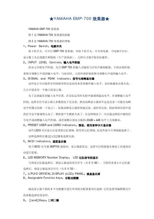
★YAMAHA EMP-700效果器★YAMAHA EMP-700效果器图1是YAMAHA-700效果器的面板图2是YAMAHA-700效果器的背板1、P ower Switch:电源开关按下此开关,可开启EMP-700效果器,再按下此开关,可关闭电源。
当电源开启后,显示板上先出现题目和版权(生产商务权),几秒后才能开始实际操作。
2、I NPUT LEVEL Controls:输入电平控制此双元并联电平控制,允许EMP 700的输入灵敏度与任何声源相配接,小的内部控制系统可调整左声道的输入电平;与此同时,大的外部控制系统可调整右声道的输入电平。
3、S IGNAL and PEAK Indicator:信号与高峰显示器这些显示可以提供有用的指导性信息而用来妥善操作输入电平,及时地避免出现失真,左右声道各有一个独立的显示器。
为了达到最佳的输入电平位置,在实际运用时先把声源调到最高电平,并调整输入电平控制。
这样在信号显示器大多数情况下会亮着,然而高峰显示器却不总是亮着(可能在高峰电平时偶尔闪烁一下而已)。
如果高峰显示器持续地亮着,或时常亮着,则表明相应的声道的信号电平被调得太高了,都快要产生跳跃失真了。
在这种情况下,可以通过降低声源的信号电平或调整输入电平控制,或者调整后部电力板的-20dB/+4dB电平工关来解决。
4、P RESET USER and CARD Indicators:预设、使用者和卡片显示器这些LEDS可以显示出是预设记忆领域、使用者记忆领域,还是外部卡片领域被选择了。
这种选择将在通过[记忆]键来选择完成。
5、M IDI Indicators:迷笛显示器每当MIDI信号被EMP700接收时,显示器就发亮,这样可以简便地从视觉上对迷笛活动进行监视。
6、L ED MEMORY Number Display: LED记忆信号的显示当预设记忆被选择后,则显示被选的项目序号(从0至90)。
当使用者或卡片记忆被选择后,则显示被选项目序号(从0至50)。
贝尔曼700安装指南和快速参考说明书

Practical Instrument Electronics82 E Main St Ste 3.14 · Webster, NY 1458Tel: 585-872-9350 · Fax: 585-872-2638 ****************· Practical Instrument Electronics, Inc. Copyright ã 2011. All rights reserved. 541-9001 Rev D 7/19/11 1-3Frequency Read & Source Functions Accuracy ± 0.005% of range Source and Read Six Ranges 1 count per hour to 20.000Khz Calibrate Totalizer input and outputs from 1 to 99999 Count Pulses 1 to 99999 LED indicator for gate time Read Function Read a wide range of Frequencies and Waveforms Read 50mV to 120V peakRead signals from Flowmeter pickups, Velocity andMotion DetectorsTotalizersSource Function Sine and Square waves, Zero Based and Zero Crossing Frequency from 1CPH to 20 KHzAdjustable amplitude from 100mV to 12Volts peak-to-peakSimulates Vibration Pickups, Variable Speed Drives and moreCalibrate Totalizers Output a number of pulses from 1 to 100 minutesGate Trigger IndicatorThe LED flashes in synch with the output frequency. This allows easy adjustment of the attenuation for proper gate triggering.Full 5 Digit Display True ±0.005% of range accuracyBar graph for quick reference of trigger level and output levels, 5% of frequency rangeHigh contrast graphic display viewable in all lighting conditions and anglesEZ-Dial ä KnobChange the speed of dialing your test point by just pushing down on the knobEZ-Check ä SwitchStop watch style push button for accurate totalizermeasurements and for high and low readingsUses a standard 9V Alkaline Battery Superior battery life of 24 hours under typical continuous usageEasy access to battery compartment 240 VAC Tolerant Fuse-less protection from accidental misuseLightweight and rugged with a solid feelConvenient Velcro® hand strap allows for a firm confident grip or attachment to pipes and ladders.APPROVED!82 E Main St Ste 3.14 · Webster, NY 1458Tel: 585-872-9350 · Fax: 585-872-2638****************· Practical Instrument Electronics, Inc. Copyright ã 2011. All rights reserved.541-9001 Rev D 7/19/11 2-3The Practical Instrument Electronics’ Model 541 is the best tool for calibration, test, and diagnosing turbine meters, frequency counters, vibration systems, tachometers, vortex shedders, integrators, and any other Frequency devices in the shop, plant and/or field. The Model 541 brings all the features you would expect from a frequency calibrator and timesaving new ones. The model 541 comes with an LED indicator showing gate time for easy trigger level adjustment. Make adjustments with the EZ-Dial ä Knob or test limits with the dual action EZ-Check ä Switch. Save hours of troubleshooting time on problems when compared to other calibration methods. When calibrating a totalizer, the model 541 eliminates the need of a stop watch. This calibrator will automatically stop when the selected number of pulses has been sent to the totalizer.General Specifications: (Unless otherwise indicated all specifications are rated from a nominal 23 °C, 70 % RH for 1 year from calibration ) Operating Temperature Range-20 to 60 °C (-5 to 140 °F) Storage Temperature Range-30 to 60 °C (-22 to 140 °F) Relative Humidity Range10 % ≤RH ≤90 % (0 to 35 °C), Non-condensing 10 % ≤RH ≤ 70 % (35 to 60 °C), Non-condensing Size7.00 X 3.30 X 2.21 inches (177.8 x 83.8 x 56.1mm) Weight12.0 oz (340 grams) Battery9V Alkaline Miscellaneous Low battery indication with nominal 1 hour of operation leftOver-voltage protection to 120 Vrms (rated for 30 seconds) or 240 Vrms (rated for 15seconds)High contrast graphic liquid crystal display with 0.45” (11.4 mm) high digitsCommon Specifications for all Frequency Modes:Frequency Ranges Specifications:1 1 CPH< CPH Range < 20000 CPH20.1 CPM (0.0167Hz)< CPM Range < 2000.0 CPM (33.33Hz) 30.01Hz < Hz < 200.00Hz 4 0.1Hz < Hz Range < 2000.0Hz 50.001KHz < KHz Range < 20.000KHz 6Totalize inputs/outputs from 1 to 99999 counts in 0.1 minutes to 100.0 minutes Read Inputs Specifications:Readx1 attenuation range: 0.1Vpk to 12Vpk x10 attenuation range: 1Vpk to 120V peak – Limit of attenuation is 120Vpk Input Impedance> 1 Meg Ω + 100pF Adjustable Signal AttenuationAdjustable trigger level with X1 and x10 attenuation ranges MiscellaneousBattery life ≥ 24 hour typical Fuse-less protection240Vrms82 E Main St Ste 3.14 · Webster, NY 1458Tel: 585-872-9350 · Fax: 585-872-2638****************· Practical Instrument Electronics, Inc. Copyright ã 2011. All rights reserved.541-9001 Rev D 7/19/11Waveforms Source Specifications:Output current >6mApp at 12Vpp output, 20KHzOutput Impedance< 25Ω Square Wave:Zero Crossing, Zero BasedSelectable Rise/Fall Time< 0.0001% of output Vpk per Second Frequency Jitter< 0.5LSB of frequency range Duty cycle50% ± 2% Sine Wave:Offset and Zero Crossing Symmetry<± 10% of Vpk Output amplitude setting Amplitude Adjustment100mV < Nominal Output < 12Vpp ± 10% of setting Calibration Certificate:NIST Traceable Certificate provided Option:Test data available upon request at additional charge. Available Options:Our equipment is guaranteed against defective material and workmanship (excluding batteries) for a period of three years from the date of shipment. Claims under guarantee can be made by returning the equipment prepaid to our factory. The equipment will be repaired, replaced or adjusted at our option. The liability of Practical Instrument Electronics (PIE) is restricted to that given under our guarantee. No responsibility is accepted for damage, loss or other expense incurred through sale or use of our equipment. Under no condition shall Practical Instrument Electronics, Inc. be liable for any special, incidental or consequential damage.。