神州数码配置命令总结 (已更新)
神州数码路由交换配置命令(全)
神州数码路由交换配置命令(全)路由 ssh aaa authentication login ssh local aaa authentication enable default enable enable password 0 123456 username admin password 0 123456 ip sshd enable ip sshd auth-methodssh ip sshd auth-retries 5 ip sshd timeout 60 TELNETR1_config#aaa authentication login default local R1_config#aaaauthentication enable default enable R1_config#enable password0 ruijie R1_config#line vty 0 4 R1_config_line#loginauthentication default R1_config_line#password 0 cisco 方法2,不需要经过3A认证R1_config#aaa authentication login default none R1_config#aaa authentication enable default enable R1_config#enable password 0 cisco R1_config#line vty 0 4 R1_config_line#login authentication default CHAP认证单向认证,密码可以不一致R2_config#aaa authentication ppp test local R2_config#username R2 password 0 123456 R2_config_s0/2#enc ppp R2_config_s0/2#ppp authentication chap test R2_config_s0/2#ppp chap hostname R1 R1_config#aaa authentication ppp test local R1_config#username R1 password 0 123456 R1_config_s0/1#enc ppp R1_config_s0/1#ppp authentication chap test R1_config_s0/1#ppp chap hostname R2 pap认证双向认证,密码要求一致R2_config#aaa authentication ppp test local R2_config#username R2 password 0 123456 R2_config_s0/2#enc ppp R2_config_s0/2#pppauthentication pap test R2_config_s0/2#ppp pap sent-usernameR1 password 123456 R1_config#aaa authentication ppp test localR1_config#username R1 password 0 123456 R1_config_s0/1#enc ppp R1_config_s0/1#ppp authentication pap testR1_config_s0/1#ppp pap sent-username R2 password 123456 FR Router-A_config_s1/1#encapsulation frame-relay !封装帧中继协议 Router-A_config_s1/1#frame-relay local-dlci 17 !设置本地DLCI 号Router-A_config_s1/1# frame-relay intf-type dce !配置FR的DCE Router-A_config_s1/1# frame-relay map 192.168.1.2 pvc 17 broadcast !配置DLCI 与对端IP的映射Vrrp Int g0/4 vrrp 1 associate 192.168.20.254 255.255.255.0 vrrp 1 priority 120 设置优先级,为主 vrrp 1 preempt 开启抢占 vrrp 1 track interface Serial0/1 30 追踪上行接口,防止上行接口DOWN了,自动降低优先级Int g0/6 vrrp 1 associate 192.168.20.254 255.255.255.0 vrrp 1 priority 100 设置优先级,为备,默认为100 vrrp 1 preempt 开启抢占vrrp 1 track interface Serial0/2 30 追踪上行接口,防止上行接口DOWN了,自动降低优先级RIP 验证,只有V2支持验证interface Serial0/2 接口起验证和配密码 ip rip authentication simple iprip password 123456RIP改单播router rip nei 192.168.1.1 RIP定时器router rip timers update 10 更新时间 timers exipire 30 失效时间 timers hosddown 50 抑制时间ospf router os 1 net 192.168.1.0 255.255.255.0 ar 0 不能写32位掩码 OSPF 虚链路 ROUTER OS2 进程起用AR 1 VI 2.2.2.2 对方ROUTER-ID OSPF 汇总ROUTER OS 2 进程起用 ar 0 range 192.168.0.0 255.255.252.0 OSPF 验证 ROUTER OS 2 明文 AR 0 AUTHEN SP 进程给需要验证的区域启用验证 INT S0/1 IP OS passw 123456 接口配置密码密文 router os 2 ar 0 authen me int s0/1 ip os me 1 md5 123456 bgp router bgp 100 no synchronization bgp全互联必须要关闭同步检查nei 192.168.12.1 remot 200 与AS外部路由建立邻居nei 2.2.2.2 remot 100 与AS内部路由建立邻居nei 2.2.2.2 up lo0 改更新接口为环回接口 nei 2.2.2.2 next-hop-self 改下一跳为自己 net 2.2.2.0 通告路由表里面有的路由ACL 路由上面的ACL要写子网掩码,不能写反掩码基于时间的ACL time-range acl 定义一个时间范围periodic weekdays 09:00 to 12:00 periodic weekdays 14:00 to 17:00 IP access-list extended time 写一个基于时间的acl,调用时间段deny ip 192.168.10.0 255.255.255.0 any time-range acl permit ip any any int g0/4 应用到接口 ip access-group time in int g0/6 ip access-group time in 静态NAT ip route 0.0.0.0 0.0.0.0 192.168.12.2 ip nat inside source static 192.168.10.10 192.168.12.1 int g0/6 ip nat in ints0/1 ip nat out NAPT ip access-list standard NAT 定义要转换的IP网段permit192.168.10.0 255.255.255.0 ip nat pool NAT 192.168.23.10192.168.23.20 255.255.255.0 创建转换的IP地址池 ip nat inside source list NAT pool NAT overload 关联要转换的IP网段和地址池 ip route default 192.168.23.3 写一条缺省路由,下一跳为出口网关的下一跳 router rip 如果跑路由协议,要把缺省重分发到动态路由 redistribute staticinterface Serial0/1 运用到内网接口ip nat inside interface Serial0/2 运用到外网接口 ip nat outside route-map ip acce sta acl 定义要匹配的流量 per 192.168.20.0255.255.255.0 route-map SHENMA 10 permit ma ip add acl 调用ACL set ip next-hop 192.168.12.1 改下一跳 int g0/3 ip po route-map SHENMA 定义到原接口 DHCP 给路由接口分配IP,不能是S口R1 ip dhcpd enable ip dhcpd pool 1network 192.168.12.0 255.255.255.0 range 192.168.12.10 192.168.12.20 R2 interface GigaEthernet0/6 ip address dhcp 给PC分配IP,底层网络要起路由互通实验全网起了RIP协议R1 ip dhcpd enable ip dhcpd pool 2 network 192.168.1.0255.255.255.0 range 192.168.1.10 192.168.1.20 default-router192.168.1.1 R2 ip dhcpd enable 要开启DHCP服务! interface GigaEthernet0/4ip address 192.168.1.1 255.255.255.0 ip helper-address192.168.12.2 设置DHCP服务器IP VPN (GRE) int t0 ipadd 172.168.10.1 255.255.255.0 给T0配IP t so s0/2 源,路由的出接口 t de 192.168.23.3 目的,对端的出接口IP,注意,要可达 t key 123456 T0口密码,两端要一致 exit ip route 192.168.20.0 255.255.255.0 t0 用T0口写一条要到达网段的静态路由int t0 ip add 172.168.10.3255.255.255.0 t so s0/1 t de 192.168.12.1 t key 123456 exit ip route 192.168.10.0 255.255.255.0 t0 VPN (IPSEC) R1 crypto ipsec transform-set SHENMA 设置转换集transform-type esp- des esp-md5-hmac 转换集的加密方式ip access-list extended 100 匹配感兴趣流 permit ip 192.168.10.0 255.255.255.0192.168.20.0 255.255.255.0 crypto map HAN 10 ipsec-isakmpset peer 192.168.23.3 设置对等体set transform-setSHENMA 关联转换集 match address 100 关联感兴趣流 interface Serial0/2 进接口调用 crypto mapHAN R3 crypto ipsec transform-set SHENMA 设置转换集transform-type esp-des esp-md5-hmac 转换集的加密方式,两端要一致ip access-list extended 100 匹配感兴趣流permit ip192.168.20.0 255.255.255.0 192.168.10.0 255.255.255.0 cryptomap HAN 10 ipsec-isakmp set peer 192.168.12.1 设置对等体 set transform-set SHENMA 关联转换集 matchaddress 100 关联感兴趣流interface Serial0/1 进接口调用crypto map HAN VPN (IKE) crypto isakmp key SHENMA 192.168.23.3 255.255.255.0 设置公共用密钥crypto isakmp policy 10 设置IKE策略 hash md5 aupre enc des group 1 lifetime 86400 crypto ipsec transform-set SHENMA 设置转换集transform-type esp-Des esp-Md5-hmac ip access-list extended 100 匹配感兴趣流permit ip 192.168.10.0 255.255.255.0 192.168.30.0 255.255.255.0 crypto map SHENMA 10 ipsec-isakmp 设置IPSEC加密映射set peer 192.168.23.3 set transform-set SHENMA match address 100 int s0/2 调用到接口 crypto map SHENMA QOS int g0/4 ipadd 192.168.10.1 255.255.255.0 no shutint g0/6 ip add 192.168.20.1 255.255.255.0 no shut int s0/1 ipadd 192.168.12.1 255.255.255.0 phy spe 64000 no shut ip route0.0.0.0 0.0.0.0 192.168.12.2 ip access-list ex 1 定义ACL抓取流量permit ip 192.168.10.0 255.255.255.0 2.2.2.0 255.255.255.0ip access-list ex 2 permit ip 192.168.20.0 255.255.255.0 2.2.2.0 255.255.255.0 priority 1 protocol ip high list 1 写一个IP协议的优先列表,调用ACL 1里面的地址,级别为HIGH priority 1 protocol ip low list 2 写一个IP协议的优先列表,调用ACL 2里面的地址,级别为LOW int s0/1 进接口调用priority 1 交换banner motd 系统登录标题 telnet telnet-server enable 开启TELNET telnet-server max-connection 16 最大连接数 ssh username ssh password 0 123456 ssh-server enable 开启SSH ssh-server timeout 60 连接超时时间ssh-server max-connection 16 最大连接数ssh-server authentication-retries 5 重连次数ssh-server host-key create rsa 创建新的主机密钥vrrp 1,首先要给所有的VLAN配上IP INT VLAN 10 IP ADD 192.168.10.1 255.255.255.0 NO SHUT 2,创建一个VRRP组ROUTER VRRP 10 VIRTUAL-IP 192.168.10.254 给虚拟IP INT VLAN 10 关联VLAN PRIORITY 120 给优先级(默认100)ENABLE 激活STP SW1 spanning-tree 开启STP spanning-tree mode mstp 改为MSTP模式spanning-tree mst configurtaion 配置域 name shenma 域名 revision-level 3 修正级别instance 1 vlan 10;20 在实例里面关联VLAN instance 2 vlan 30;40 exit spanning-tree mst 1 priority 4096 给实例配置优先级,越小的级别越高spanning-tree mst 2 priority 8192 SW2 spanning-tree 开启STP spanning-tree mode mstp 改为MSTP模式spanning-tree mst configurtaion 配置域name shenma 域名revision-level 3 修正级别 instance 1 vlan 10;20 在实例里面关联VLAN instance 2 vlan 30;40 exit spanning-tree mst 1 priority 8192 给实例配置优先级,越小的级别越高spanning-tree mst 2 priority 4096 SW21 spanning-tree 开启STP spanning-tree mode mstp 改为MSTP模式 spanning-tree mst configurtaion 配置域 name shenma 域名 revision-level 3 修正级别 instance 1 vlan 10;20 在实例里面关联VLANinstance 2 vlan 30;40 AM端口安全 am enable int e1/0/1 am port am mac-ip-pool 0000.1111.2222 192.168.10.1 端口镜像monitor session 1 source int e1/0/1 both monitor session 1 destination int e1/0/15 RIP Router rip Net 192.168.1.0/24 Router os 1 Net 192.168.1.0 0.0.0.255 ar 0 Acl Firewall enableIp access-list ex 100 Per ip 192.168.1.0 0.0.0.255 192.168.2.00.0.0.255 单臂路由R1 int g0/5 no shut interface GigaEthernet0/5.1 encapsulation dot1Q 100 ip address 192.168.10.1 255.255.255.0 interface GigaEthernet0/5.2 encapsulation dot1Q 200 ip address 192.168.20.1 255.255.255.0 interface GigaEthernet0/5.3 encapsulation dot1Q 300 ip address 192.168.30.1 255.255.255.0SW1 vlan 100\ sw int e1/0/1-2 vlan 200 sw int e1/0/3-4 vlan 300 sw int e1/0/5-6 int e1/0/20 sw mo tr sw tr all vlan all 端口聚合 PORT-GROUP 1 创建一个组 INT E1/0/17-18 聚合端口要设置为TRUNK SW MO TR SW TR ALL VLAN ALL PORT-GROUP 1 MO ON 设置聚合端口的模式为自动匹配EXIT INT PORT-CHANNAL 1 进入聚合端口配置模式,也要设置为TRUNK SW MO TR SW TR ALL VLAN ALL EXIT dhcp SERV DHCP 开启DHCP服务IP DHCP POOL VLAN10 创建地址池NETW 192.168.10.0 255.255.255.0 def 192.168.10.1 le 2 dns 8.8.8.8 ipdhcp ex 192.168.10.1 192.168.10.10 排除地址范围 dhcp 中继serv dhcp ip for udp boot int vlan 10 ip he 192.168.12.2dhcp snooping serv dhcp 开启DHCP服务ip dhcp snooping enable 开启DHCP SNOOPING 功能ip dhcp snooping binding enable 开启SNOOPING 绑定功能 int e1/0/20 ip dhcp snooping trust 设置接口为信任接口,一般是与服务器相连的接口 int e1/0/1 ip dhcp snooping binding user-control 设置端口自动绑定获取DHCP的地址设置端口手动绑定MAC,VLAN,IP,端口信息(全局模式)ip dhcp snooping binding user 00-11-22-33-44-55 address 192.168.22.22 vlan 1 int e1/0/5 ipv6 6 to 4 greipv6 unicast-routing 允许单播路由interface Tunnel0 ipv6enable 开启IPV6 ipv6 address 2001:23::1/64 tunnel source 192.168.12.1 本端接口地址 tunnel destination 192.168.12.2 对端接口地址tunnel mode gre ip 隧道模式改为GRE tunnel key 123456 隧道密码,两端一致 ipv6 route 3::/64 Tunnel0 写一条下一跳为TUNNEL 0的IPV6静态,不能写默认静态nat Internet(config)#ip route 0.0.0.0 0.0.0.0 fa0/1ipv4网络要可达NAT-PT(config)#ip route 0.0.0.0 0.0.0.0fa0/1NAT-PT(config)#ipv6 nat prefix 2001:db8:feed::/96 设置一个全局NAT前缀,掩码必须96位NAT-PT(config)#ipv6 nat v4v6 source 10.10.10.2 2001:db8:feed::2 写4 TO 6 地址转换,需要到达的地址都要写, 不需要与本地同一网段NAT-PT(config)#ipv6 nat v4v6 source 192.168.1.10 2001:db8:feed::3 NAT-PT(config)#ipv6 nat v6v4 source 2001:db8:cafe:ffff::2 10.10.20.5 写6 to 4 地址转换,需要到达的地址都要写,不需要与本地同一网段 int g0/4 调用到接口,进出都要调用 ipv6 natint g0/4 ipv6 nat pat ipv4 网络要可达NAT-PT(config)#ipv6 nat prefix 2001:db8:feed::/96 设置一个全局NAT前缀,掩码必须96位NAT-PT(config)#ipv6 nat v4v6 source 10.10.10.2 2001:db8:feed::2 写4 TO 6 地址转换,需要到达的地址都要写NAT-PT(config)#ipv6 nat v4v6 source 192.168.1.10 2001:db8:feed::3 不需要与本地同一网段NAT-PT(config)#ipv6 access-list cafe 把IPV6要转换的网段匹配出来NAT-PT(config-ipv6-acl)#permit ipv6 2001:db8:cafe::/48 any NAT-PT(config-ipv6-acl)#exit NAT-PT(config)#ipv6 nat v6v4 pool ipv4 10.10.20.5 10.10.20.6 prefix-length 24 写一个6 TO 4 的NAT地址池,不需要已知网段 NAT-PT(config)#ipv6 nat v6v4 source list cafe pool ipv4 overload 把要转换的网段与地址池关联int g0/4 ipv6 nat int g0/4 ipv6 nat riping ipv6 router rip 100 全局创建RIP实例,名字为100 exit interface GigaEthernet0/4ipv6 enable 开启IPV6 ipv6 address 2001::1/64 ipv6 rip 100 enable 启动为100的实例需要宣告的接口要设置ospfv3 ipv6 router ospf 1 全局创建ospf,进程为1 int g0/6 ipv6 enable ipv6 address 2001::1/64 ipv6 ospf 1 area 0 宣告本接口为 area 0 需要宣告的接口要设置。
神州数码交换机路由器命令
神州数码交换机路由器命令神州数码交换机路由器命令交换机配置命令switch>en (enable)进入特权用户模式switch # conf (config) 进入全局配置模式switch (config)# int e0/0/1 进入接口配置模式switch (config)# int vlan 1 进入VLAN配置模式switch (config)# host (hostname) 配置交换机名称switch (config)# enable password 1234 配置交换机密码switch (config)# enable password 8 1234 配置交换机密码(加密)switch (config)# vlan 10 创建vlanswitch (config)# int vlan 10switch (config-If-Vlan10)# ip address 172.16.10.1 255.255.255.0 配置VLAN地址生成树技术Switch (config)# spanning-tree 启用全局生成树(默认mstp生成树技术)switch (config)# spanning-tree mode stp/rstp/mstp 生成树技术switch (config)# spanning-tree mst 0 port-priority 4096 设置交换机的优先级默认32768Switch# sh sp (show spanning-tree) 查看生成树交换机Web管理switch (config)# ip http serverswitch (config)# web-user admin password 0 1234 用户名和密码(命令要全写)交换机T elnet管理switch (config) # ip http serverswitch (config)# telnet-user admin password 0 1234 用户名和密码(命令要全写)清空交换机配置switch# set def (default)恢复出厂配置switch# wr (write)保存配置switch# rel (reload)重启交换机链路聚合(不需启动生成树)switchA(config)# port-group 1switchA(config)# int e0/0/1-2switchA(config-port-range)# port-group 1 mode on/active 手动配置/自动配置switchA(config)# no port-group 1 删除组1switchB(config) # port-group 2switchB(config) # int e0/0/3-4switchB(config-port-range) # port-group 2 mode on/active switchA(config) # no port-group 2 删除组2交换机MAC与IP绑定switch (config)# am enable 启用全局am功能switch (config)# int e0/0/1switch (config_if_ethernet0/0/1)# am port 打开端口am功能switch (config_if_ethernet0/0/1)# am mac-ip-pool 00-A0-D1-D1-07-FF 192.168.1.101交换机DHCP服务器配置switch (config)# service dhcp 启用DHCPswitch (config)# ip dhcp pool poolA 定义地址池poolAswitch (dhcp-poolA- config)# network-address 192.168.1.0 24switch (dhcp-poolA- config)# lease 3 租期3天switch (dhcp-poolA- config)# default-router 192.168.1.1 网关switch (dhcp-poolA- config)# dns-server 60.191.244.5 DNS服务器ACL访问控制列表switchA(config)# ip access-list standard test 命名标准IP访问列表switchA(config-std-nacl-test)# deny 192.168.100.0 0.0.0.255 反子网掩码switchA(config-std-nacl-test)# deny 192.168.200.0 0.0.0.0switchA(config) # firewall enable 开启ACL功能switchA(config)# firewall default permit/deny 默认permit允许switchA(config)# int e0/0/1switchA(config-if-interface0/0/1) # ip access-group test in/outswitchA(config) # ip access-list standard 10 数字标准IP访问列表配置时间范围switchA(config)#time-range worktimeswitchA(config-time-range)#absolute-periodic weekdays 09:00:00 to 18:00:00路由器配置命令Router>ena 进入特权用户模式 Router# conf 进入全局配置模式Router_config# int f0/0Router_config_f0/0# ip address 10.1.1.1 255.255.255.0 配置路由器端口地址清空路由器配置Router# del (delete)删除启动配置文件Router# reb (reboot) 重启路由器静态路由Router_config# ip route 10.1.2.0 (目标网段) 255.255.255.0(子网掩码) 10.1.1.1 (转发地址)默认静态路由Router_config# ip route 0.0.0.0 (目标网段) 0.0.0.0(子网掩码)10.1.1.1 (转发地址)RIP动态路由Router_config# router rip 启用RIP路由Router_config_rip# version 2 RIP路由版本号 2Router_config_rip# network 10.1.1.0 255.255.255.0Router_config_rip# network 10.1.2.0 255.255.255.0 与路由器相连的网段OSPF动态路由Router_config# router ospf 1 启动ospf进程,进程号为1Router_config_ospf1# network 10.1.1.0 255.255.255.0 area 0 网段、子网掩码和区域号Router_config_ospf1# network 10.1.2.0 255.255.255.0 area 0 第一个区域(即主干区域)区域号为 0Router# show ip route 查看路由。
神州数码设备配置总结.doc
神州数码设备配置总结交换机实验交换机的堆叠实验:3526s没有堆叠配置但堆叠的个数为不能超过8台交换机.而3926s堆叠个数不能超过9台。
堆叠(stack)协议是一种交换机管理技术,可将物理上的若干台交换机堆叠在一起,逻辑上当成一台交换机进行管理。
根据交换机之间连接方式的不同,堆叠交换机有三种配置方式:1.simplex方式:一台交换机的TX端口和另一台交换机的RX端口之间通过单向数据线连接,从而形成一个单向链路环。
simplex方式形成的堆叠组,每台交换机只需要一个全双工端口用于堆叠交换机之间的通讯。
缺点是容错性较差,任何一条链路出现故障,都会造成堆叠组瘫痪。
图 6-1 simplex方式2.duplex方式:交换机之间通过双向数据线连接形成双向两路环。
duplex方式形成的堆叠组,每台交换机必须两个全双工端口用于堆叠交换机之间的通讯。
为避免形成数据环,堆叠协议把其中一条数据链路作为冗余链路,并设置为PASSIVE状态。
Duplex堆叠方式具有较好的容错性,如果一条数据链路出现故障,堆叠协议可以启用冗余链路进行通讯,从而可以保持堆叠组稳定运行。
为节约级联端口,也可以取消冗余链路,而把交换机链接成为线形。
图 6-2 duplex方式3.chassis方式:以一台高性能交换机作为MASTER形成星形。
Chassis堆叠方式,任一两台交换机之间进行通讯,都必需经过MASTER交换机。
MASTER交换机必须是一台处理能力较强的高性能交换机,否则容易形成通讯瓶颈。
3926s的堆叠配置:图 6-3 chassis方式DCS-3926S支持duplex堆叠方式,下面我们就来看一下如何配置交换机堆叠。
目前,DCS-3926S支持duplex堆叠方式。
堆叠交换机启动后,首先运行MDP(MasterDiscovery Protocol)选举一台交换机作为MASTER,其它交换机作为SLAVE。
MASTER负责管理所有SLAVE交换机,并负责为每台SLAVE分配一个ID号,MASTER的ID为0。
神州数码配置命令总结
第一部分交换机配置一、基础配置1、模式进入Switch>Switch>enSwitch#configSwitch(Config)#interface ethernet 0/22、配置交换机主机名命令:hostname <主机名>3、配置交换机IP地址Switch(Config)#interface vlan 1Switch(Config-If-Vlan1)#ip address 10.1.128.251 255.255.255.0Switch(Config-If-Vlan1)#no shut4、为交换机设置Telnet授权用户和口令:telnet-user <用户名>password {0|7} <密码>例:Switch(Config)#telnet-user test password 0 test5、为交换机设置Web授权用户和口令:web-user <用户名>password {0|7} <密码>例:Switch(Config)#web-user admin password 0 digital6、设置系统日期和时钟:clock set <HH:MM:SS> <YYYY/MM/DD>7、设置退出特权用户配置模式超时时间exec timeout <minutes > //单位为分钟,取值范围为0~3008、保存配置:write9、显示系统当前的时钟:Switch#show clock10、指定登录用户的身份是管理级还是访问级Enable [level {visitor|admin} [<密码>]]11、指定登录配置模式的密码:Enable password level {visitor|admin}12、设置端口的速率和双工模式(接口配置模式下)命令:speed-duplex {auto | force10-half | force10-full | force100-half | force100-full | {{force1g-half | force1g-full} [nonegotiate [master | slave]] } }no speed-duplex二、单交换机VLAN划分1、VLAN基本配置(1)新建VLAN:vlan <vlan-id>(2)命名VLAN:name <vlan-name>(3)为VLAN 分配交换机端口Switch(Config-If-Vlan1)#switchport interface Ethernet 0/2(4)设置Trunk 端口允许通过VLAN:Switch(Config-ethernet0/0/5)#switchport trunk allowed vlan 1;3;5-202、划分VLAN:(1)进入相应端口:Switch(config)#interface Ethernet 0/2(2)修改模式:Switch(Config-ethernet0/0/5)switchport mode access(3)划分VLAN:Switch(Config-ethernet0/0/5)#switchport access vlan 4三、跨交换机VLAN划分(两台交换机作相同操作)1、新建VLAN2、划分VLAN3、修改链路模式(1)进入相应端口:Switch(config)#interface Ethernet 0/1(2)修改模式:Switch(config-if)#switchport mode trunk四、VLAN间主机的通信1、新建VLAN2、划分VLAN3、修改链路模式(1)进入相应端口:Switch(config)#interface Ethernet 0/1(2)修改模式:Switch(config-if)#switchport mode trunk注意:如果是三层交换机,在修改模式先封装802.1协议:Switch(config-if)#switchport trunk encapsulation dot1q4、建立VLAN子接口(1)、进入VLAN接口模式:Switch(config)#interface vlan 2(2)、设置VLAN子接口地址:Switch(config-if)#ip address 192.168.0.1 255.255.255.0(3)、打开端口:Switch(config-if)#no shutdown5、设置各主机IP地址、子网掩码、网关注意:(1)各主机IP地址应与其所在的VLAN在同一网段。
神州数码路由器配置相关命令
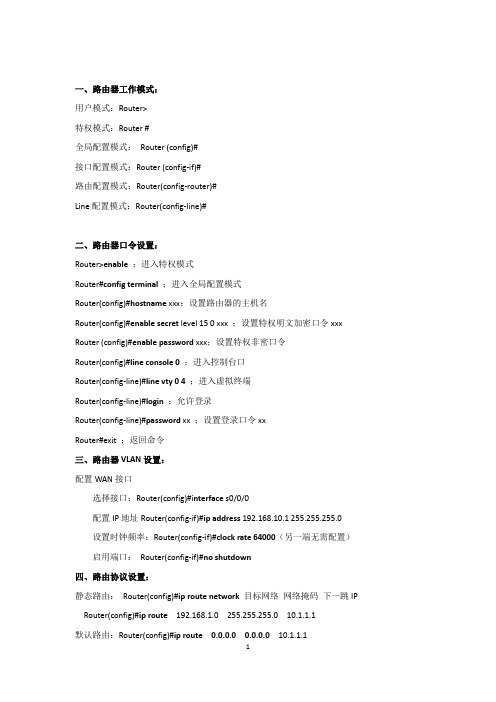
一、路由器工作模式:用户模式:Router>特权模式:Router #全局配置模式:Router (config)#接口配置模式:Router (config-if)#路由配置模式:Router(config-router)#Line配置模式:Router(config-line)#二、路由器口令设置:Router>enable;进入特权模式Router#configterminal;进入全局配置模式Router(config)#hostname xxx;设置路由器的主机名Router(config)#enable secret level 15 0 xxx ;设置特权明文加密口令xxx Router (config)#enable password xxx;设置特权非密口令Router(config)#line console 0;进入控制台口Router(config-line)#line vty 0 4;进入虚拟终端Router(config-line)#login;允许登录Router(config-line)#password xx ;设置登录口令xxRouter#exit;返回命令三、路由器VLAN设置:配置WAN接口选择接口:Router(config)#i nterface s0/0/0配置IP地址Router(config-if)#ip address 192.168.10.1 255.255.255.0设置时钟频率:Router(config-if)#clock rate 64000(另一端无需配置)启用端口:Router(config-if)#no shutdown四、路由协议设置:静态路由:Router(config)#ip route network 目标网络网络掩码下一跳IP Router(config)#ip route 192.168.1.0 255.255.255.0 10.1.1.1默认路由:Router(config)#ip route 0.0.0.0 0.0.0.0 10.1.1.1开启RIP协议:Router(config)#router rip指定版本协议:Router(config-router)#version 2声明直连网络号:Router(config-router)#network 直连网段Router(config-router)#network 192.168.1.0开启进程号为1的ospf协议:Router(config)#router ospf1声明直连网络号Router(config-router)#network直连网段反掩码area区域号Router(config-router)#network 192.168.1.0 0.0.0.255 area 0查看路由表:Router#showip route配置路由访问控制命令格式:Router(config)#access-list 列表号permit源IP地址反掩码配置允许:Router(config)#access-list 1 permit 192.168.10.1 0.0.0.255配置拒绝访问:Router(config)# access-list 1 deny 192.168.20.0 0.0.0.255配置允许其他:Router(config)#access-list 1 permit any端口绑定命令:进入相应端口:Router(config)#interface fa0/1配置列表防止位置:Router(config-if)#ip access-group 1 outRouter(config-if)#配置路由DHCP服务开启dhcp服务:Router(config)#service dhcp设置地址池:Router(config)#ipdhcp pool 172.16.12.0设置网段:Router(dhcp-config)#network 172.16.12.0 255.255.255.0设置默认网关:Router(dhcp-config)#default-router 172.16.12.200Router(dhcp-config)#exit设置排除地址:Router(config)#ipdhcp excluded-address 172.16.12.151 172.16.12.254 进入网关端口:Router(config)#interface g0/0设置网关IP:Router(config-if)#i p address 172.16.12.200 255.255.255.0配置路由NAT静态NATRouter1(config)#ipnat inside source static 192.168.11.2 200.200.200.3Router1(config)#interface fa0/0Router1(config-if)#ipnat insideRouter1(config)#interface Serial0/0/0Router1(config-if)#ipnat outside动态NATRouter1(config)#ipnat pool NAT 200.200.200.3 200.200.200.4 network 255.255.255.0//定义内部全局IP地址池NAT Router1(config)#access-list 1 permit 192.168.11.00.0.0.255 //定义可转换内部本地IP地址Router1(config)#ipnat inside source list 1 pool NAT //配置动态NAT映射Router1(config)#interface fa0/0 //定义内部接口Router1(config-if)#ipnat insideRouter1(config)#interface Serial0/0/0 //定义外部接口Router1(config-if)#ipnatoutsideRouter1(config-if)#no shutdown路由器显示命令:Router#dir Flash: ;查看闪存Router#write;保存配置信息Router#show run;查看当前配置信息Router#show ip access-list //查看ACL配置信息Router#clean ipnat translation //清除动态NA T转换列表信息Route#show ipnat statistics //查看NA T转换统计信息Route#clean ipnat statistics //清除NA T转换统计信息完了最最要的一步。
神州数码路由和交换器命令
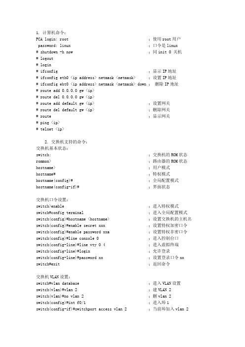
1. 计算机命令:PCA login: root ;使用root用户password: linux ;口令是linux# shutdown -h now ;同init 0 关机# logout# login# ifconfig ;显示IP地址# ifconfig eth0 <ip address> netmask <netmask> ;设置IP地址# ifconfig eht0 <ip address> netmask <netmask> down ;删除IP地址# route add 0.0.0.0 gw <ip># route del 0.0.0.0 gw <ip># route add default gw <ip> ;设置网关# route del default gw <ip> ;删除网关# route ;显示网关# ping <ip># telnet <ip>2. 交换机支持的命令:交换机基本状态:switch: ;交换机的ROM状态rommon> ;路由器的ROM状态hostname> ;用户模式hostname# ;特权模式hostname(config)# ;全局配置模式hostname(config-if)# ;界面状态交换机口令设置:switch>enable ;进入特权模式switch#config terminal ;进入全局配置模式switch(config)#hostname <hostname> ;设置交换机的主机名switch(config)#enable secret xxx ;设置特权加密口令switch(config)#enable password xxa ;设置特权非密口令switch(config)#line console 0 ;进入控制台口switch(config-line)#line vty 0 4 ;进入虚拟终端switch(config-line)#login ;允许登录switch(config-line)#password xx ;设置登录口令xx switch#exit ;返回命令交换机VLAN设置:switch#vlan database ;进入VLAN设置switch(vlan)#vlan 2 ;建VLAN 2switch(vlan)#no vlan 2 ;删vlan 2switch(config)#int f0/1 ;进入埠1switch(config-if)#switchport access vlan 2 ;当前埠加入vlan 2switch(config-if)#switchport mode trunk;设置为干线switch(config-if)#switchport trunk allowed vlan 1,2 ;设置允许的vlan switch(config-if)#switchport trunk encap dot1q ;设置vlan 中继switch(config)#vtp domain <name> ;设置发vtp域名switch(config)#vtp password <word> ;设置发vtp密码switch(config)#vtp mode server ;设置发vtp模式switch(config)#vtp mode client ;设置发vtp模式交换机设置IP地址:switch(config)#interface vlan 1 ;进入vlan 1switch(config-if)#ip address <IP> <mask> ;设置IP地址switch(config)#ip default-gateway <IP> ;设置默认网关switch#dir flash: ;查看闪存交换机显示命令:switch#write ;保存配置信息switch#show vtp ;查看vtp配置信息switch#show run ;查看当前配置信息switch#show vlan ;查看vlan配置信息switch#show interface ;查看端口信息switch#show int f0/0 ;查看指定端口信息3. 路由器支持的命令:路由器显示命令:router#show run ;显示配置信息router#show interface ;显示接口信息router#show ip route ;显示路由信息router#show cdp nei ;显示邻居信息router#reload ;重新起动路由器口令设置:router>enable ;进入特权模式router#config terminal ;进入全局配置模式router(config)#hostname <hostname> ;设置交换机的主机名router(config)#enable secret xxx ;设置特权加密口令router(config)#enable password xxb ;设置特权非密口令router(config)#line console 0 ;进入控制台口router(config-line)#line vty 0 4 ;进入虚拟终端router(config-line)#login ;要求口令验证router(config-line)#password xx ;设置登录口令xx router(config)#(Ctrl+z) ;返回特权模式router#exit ;返回命令路由器配置:router(config)#int s0/0 ;进入Serail界面router(config-if)#no shutdown ;启动当前接口router(config-if)#clock rate 64000 ;设置同步时钟router(config-if)#ip address <ip> <netmask> ;设置IP地址router(config-if)#ip address <ip> <netmask> second ;设置第二个IP router(config-if)#int f0/0.1 ;进入子界面router(config-subif.1)#ip address <ip> <netmask> ;设置子界面IP router(config-subif.1)#encapsulation dot1q <n> ;绑定vlan中继协议router(config)#config-register 0x2142 ;跳过配置文件router(config)#config-register 0x2102 ;正常使用配置文件router#reload ;重新引导路由器檔操作:router#copy running-config startup-config ;保存配置router#copy running-config tftp ;保存配置到tftp router#copy startup-config tftp ;开机配置存到tftp router#copy tftp flash: ;下传文件到flash router#copy tftp startup-config ;下载配置文件ROM状态:Ctrl+Break ;进入ROM监控状态rommon>confreg 0x2142 ;跳过配置文件rommon>confreg 0x2102 ;恢复配置文件rommon>reset ;重新引导rommon>copy xmodem:<sname> flash:<dname> ;从console传输文件rommon>IP_ADDRESS=10.65.1.2 ;设置路由器IP rommon>IP_SUBNET_MASK=255.255.0.0 ;设置路由器屏蔽rommon>TFTP_SERVER=10.65.1.1 ;指定TFTP服务器IP rommon>TFTP_FILE=c2600.bin ;指定下载的檔rommon>tftpdnld ;从tftp下载rommon>dir flash: ;查看闪存内容rommon>boot ;引导IOS静态路由:ip route <ip-address> <subnet-mask> <gateway> ;命令格式router(config)#ip route 2.0.0.0 255.0.0.0 1.1.1.2 ;静态路由举例router(config)#ip route 0.0.0.0 0.0.0.0 1.1.1.2 ;默认路由举例动态路由:router(config)#ip routing ;启动路由转发router(config)#router rip ;启动RIP路由协定。
神州数码配置命令归纳(已更新)
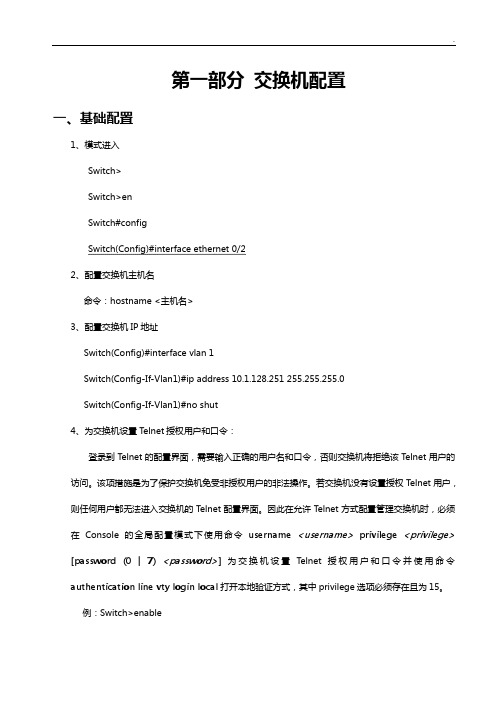
第一部分交换机配置一、基础配置1、模式进入Switch>Switch>enSwitch#configSwitch(Config)#interface ethernet 0/22、配置交换机主机名命令:hostname <主机名>3、配置交换机IP地址Switch(Config)#interface vlan 1Switch(Config-If-Vlan1)#ip address 10.1.128.251 255.255.255.0Switch(Config-If-Vlan1)#no shut4、为交换机设置Telnet授权用户和口令:登录到Telnet的配置界面,需要输入正确的用户名和口令,否则交换机将拒绝该Telnet用户的访问。
该项措施是为了保护交换机免受非授权用户的非法操作。
若交换机没有设置授权Telnet用户,则任何用户都无法进入交换机的Telnet配置界面。
因此在允许Telnet方式配置管理交换机时,必须在Console的全局配置模式下使用命令username <username>privilege <privilege> [password (0 | 7) <password>]为交换机设置Telnet授权用户和口令并使用命令authentication line vty login local打开本地验证方式,其中privilege选项必须存在且为15。
例:Switch>enableSwitch#configSwitch(config)#username test privilege 15 password 0 testSwitch(config)#authentication line vty login localSwitch(Config)#telnet-user test password 0 testSwitch (Config)#telnet-server enable://启动远程服务功能5、配置允许Telnet管理交换机的地址限制(单独IP或IP地址段)(1)限制单个IP允许Telnet登录交换机switch(config)#authentication security ip 192.168.1.2(2)限制允许IP地址段Telnet登录交换机switch(config)#access-list 1 permit 192.168.1.0 0.0.0.255switch(config)#authentication ip access-class 1 in5、为交换机设置Web授权用户和口令:web-user <用户名>password {0|7} <密码>例:Switch(Config)#web-user admin password 0 digital6、设置系统日期和时钟:clock set <HH:MM:SS> <YYYY/MM/DD>7、设置退出特权用户配置模式超时时间exec timeout <minutes > //单位为分钟,取值范围为0~3008、保存配置:write9、显示系统当前的时钟:Switch#show clock10、指定登录用户的身份是管理级还是访问级Enable [level {visitor|admin} [<密码>]]11、指定登录配置模式的密码:Enable password level {visitor|admin}12、配置交换机的用户名密码:username admin privilege 15 password 0 admin00013、配置enable密码为ddd:enable password 0 ddd level 1514、配置登录时认证:authentication line vty login local15、设置端口的速率和双工模式(接口配置模式下)命令:speed-duplex {auto | force10-half | force10-full | force100-half | force100-full | {{force1g-half | force1g-full} [nonegotiate [master | slave]] } }no speed-duplex二、单交换机VLAN划分1、VLAN基本配置(1)新建VLAN:vlan <vlan-id>(2)命名VLAN:name <vlan-name>(3)为VLAN 分配交换机端口Switch(Config-If-Vlan1)#switchport interface Ethernet 0/2(4)设置Trunk 端口允许通过VLAN:Switch(Config-ethernet0/0/5)#switchport trunk allowed vlan 1;3;5-202、划分VLAN:(1)进入相应端口:Switch(config)#interface Ethernet 0/2(2)修改模式:Switch(Config-ethernet0/0/5)switchport mode access(3)划分VLAN:Switch(Config-ethernet0/0/5)#switchport access vlan 4三、跨交换机VLAN划分(两台交换机作相同操作)1、新建VLAN2、划分VLAN3、修改链路模式(1)进入相应端口:Switch(config)#interface Ethernet 0/1(2)修改模式:Switch(config-if)#switchport mode trunk四、VLAN间主机的通信1、新建VLAN2、划分VLAN3、修改链路模式(1)进入相应端口:Switch(config)#interface Ethernet 0/1(2)修改模式:Switch(config-if)#switchport mode trunk注意:如果是三层交换机,在修改模式先封装802.1协议:Switch(config-if)#switchport trunk encapsulation dot1q4、建立VLAN子接口(1)、进入VLAN接口模式:Switch(config)#interface vlan 2(2)、设置VLAN子接口地址:Switch(config-if)#ip address 192.168.0.1 255.255.255.0 (3)、打开端口:Switch(config-if)#no shutdown5、设置各主机IP地址、子网掩码、网关注意:(1)各主机IP地址应与其所在的VLAN在同一网段。
神州数码交换机路由器常用命令操作
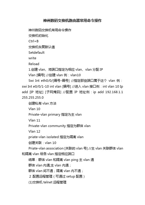
神州数码交换机路由器常用命令操作神州数码交换机常用命令操作交换机初始化Ctrl+B交换机恢复默认值SetdefaultwriteReload1.创建vlan、将端口指定为相应vlan、vlan分配IPVlan [编号] //创建vlan 例:vlan10Swi Int eth0/0/[编号-编号] //指定那些端口属于这个vlan 例:swi Int e0/0/1-10 int vlan [编号] //进入vlan接口例:int vlan 10 Ip add [IP地址] [子网掩码] //配置IP地址例:ip add 192.168.1.1 255.255.255.0创建私有vlan方法Vlan 10Private-vlan primary 指定为主vlanVlan 11Private-vlan community 指定为群体vlanVlan 12priate-vlan isolated 指定为隔离vlan创建关联:vlan 10Priate-vlan association [关联的vlan号] //主vlan关联群体vlan 和隔离vlan 给各vlan指定相应端口结果:群体vlan和隔离vlan ping主vlan 通群体vlan内通;主vlan 内通;群体vlan间不通;隔离vlan内不通;2.配置远程管理(可通过setup配置)(1)交换机telnet远程管理telnet-server enable //开启telnet服务,默认以开启telnet-user [用户] password 0 [密码] //添加telnet管理用户(2)web服务管理Ip http sever //开启web服务,需手动开启Web-user [用户名] password 0 [密码] //添加web管理用户3.静态路由Ip route [目标地址段] [目标掩码] [下一跳IP/接口]Ip route 0.0.0.0 0.0.0.0 [下一跳IP/接口] //ip route 0.0.0.0 0.0.0.0 192.168.1.2 4.RIP协议路由以Vlan方法Router ripName[名称]Networkvlan[编号] //networkvlan10以IP方法Router ripName [名称]Network [ip段]5.ospf协议路由以Vlan方法Router ospf [ 编号] //默认编号是1Int vlan [vlan号] //int vlan 10 [区域号]默认为0,必须有Ip ospf enable area [区域号] //ip ospf enable area 0以IP方法Router ospf [ 编号]Router-id [ip地址]Network [自己的IP] [网关] area 0 //network 192.168.1.1/24 area 0 6.生成树协议1)Stp模式配置spanning-tree //启用生成树spanning-tree mode stp //设置生成树模式spanning-tree mst 0 priority 4096 //设置生成树交换机优先级2)mstp的配置spanning-treespanning-tree mst configurationname [名称]instance [实例号] vlan [编号]spanning-tree mst [实例号] priority 4096 //设置生成树交换机优先级spanning-tree mst [实例号] port-priority 16 //设置生成树端口优先级3)配置成快速启用端口Int e0/0/[编号-编号]Spanning-tree portfast7.链路聚合(手工)port-group [组号] //创建聚合组号int e0/0/[做链路的那几个端口号] //将端口加入聚合组port-group [组号] mode on8.链路聚合(LACP动态生成)port-group [组号]int e0/0/[做链路的那几个端口号](交换机A的配置)port-group [组号] mode active(交换机B的配置)port-group [组号] mode passive9.trunkInt e0/0/[端口]Sw mode trunk //设置为trunkSw trunk allowed vlan all //划分到所有vlan10.Mac地址和端口绑定(单个)Int e0/0/[端口]Sw port-securitySw port-security mac-address [mac地址]11.Mac地址和端口绑定(多个)Inte0/0/[端口]Sw port-securitySw port-security maximum [安全mac地址个数如:3]sw port-security mac-address [mac地址]sw port-security mac-address [mac地址]sw port-security mac-address [mac地址]12.Mac地址和端口绑定(动态学习)Int e0/0/[端口]Sw port-security maximumSw port-security maximum lockSw port-security maximum convert13.mac地址表绑定mac-address-table static address[mac地址]vlan[编号]inte0/0/[编号]//解释:让mac地址只能在指定vlan中的指定端口中使用,其他的都不能使用(未测试) 14. 端口安全1) int e0/0/1-10 //进入端口,只能在access口上配置2) switchport port-security //开启端口安全功能3) switchport port-security maximum 5 //配置端口安全最大连接数4) sw port-security violation shutdown //配置违例处理方式5).sw port-security mac-address [mac地址] //配置mac地址绑定15. 交换机端口镜像(将源端口数据复制到目标端口)1) monitor session 1 source interface fastEthernet 0/2 both //源端口、被镜像的端口2) monitor session 1 destiNation interface fastEthernet 0/3 //目标端口、镜像端口16.dhcp配置1)交换机做dhcp服务器配置Service dhcp //启用DHCP服务Ip dhcp pool [地址池名]Network-address [IP段如:192.168.1.0] [掩码数如:24]Lease[租用天数]Default-router[网关IP]Dns-server[DNS的IP]Ip dhcp excluded-address<开始地址><结束地址>//指定网段中不分配的IP地址2)Dhcp中继服务的配置Service dhcpIp forward-protocol udp bootps //配置DHCP中继转发port 端口的UDP广播报文,默认67端口Int vlan [编号]或在接口上配置//int e0/0/[编号]Ip help-address [服务器IP] //指定DHCP中继转发的UDP报文的目标地址17.ACL IP访问控制下面2条是开启ACLFirewall enable //开启包过滤功能Firewall default permit //设置默认动作为允许//定义标准访问控制列表 //定义访问列表Ip access-list standard test //在端口上应用列表Deny 192.168.1.100.00.0.0.0.255//禁止IP段访问Deny 192.168.200.11 0.0.0.0//禁止单个IP访问Denytcp192.168.200.00.0.0.255any-destinationd-port23//拒绝IP段telnet数据Permit192.168.1.100.00.0.0.0.255//允许IP段访问Deny192.168.200.110.0.0.0//允许IP访问//绑定ACL到各个端口Inte0/0/[端口]Ip access-group test in//验证方法Show access-group标准ACL实验1) access-list 1 deny 192.168.1.0 0.0.0.255 //拒绝访问的IP段2) access-list 1 permit 192.168.1.0 0.0.0.255 //允许的IP段3) //进入端口4) ip access-group 1 in //把控制列表1 配入端口,进入控制5) ip access-group 1 out //把控制列表1 配入端口,输出控制15. 扩展ACL实验1) access-list 101 deny tcp A.B.C.D 255.255.255.0 A.B.C.D 255.255.255.0 eq ftp(WWW)// 禁止前面个网段访问后面个网段的ftp或者WWW16. 交换机单向访问控制1) //使用标准ACL2) access-list 1 deny 192.168.1.0 0.0.0.2553) //进入端口4) ip access-group 1 in神州数码路由器常用命令操作路由器初始化:ctrl+breakNopassword路由器恢复默认值dirDel startup-configReboot1.进入端口给端口分配IPInt [端口]Ip add [ip] [子网掩码]No shuFC串口配置时钟频率Ph sp 640002.静态路由Ip route [目标地址段] [目标掩码] [下一跳IP/接口]Ip route 0.0.0.0 0.0.0.0 [下一跳IP/接口] //默认路由Ip route 0.0.0.0 0.0.0.0 [下一跳IP/接口] 10 //浮动路由3.RIP协议路由Router ripNetwork [ip段]4.ospf协议路由Router ospf [进程号]Router-id [ip地址]Network [自己的IP段] [子网掩码] area [区域号如:0]5.telnet开启方法1Aaa authen enable default lineAaa authen login default lineEnable passwd [密码]Line vty 0 4Password [密码]方法2Username [用户名] password [密码]Aaa authentication login [用户名] localLine vty 0 4Login authentication [刚刚那个用户名]6.web访问配置Username [用户] password 0 [密码] //添加用户Ip http webm-type[web配置方式] //选择方式.高级,典型,向导Ip http port[端口] //配置web端口7.ppp协议时钟频率physical-layer speed 64000封装PPP协议Int s0/[编号]Enc ppp //封装PPP协议单向验证(验证方式为PAP和CHAP)验证方Aaa authen ppp default localUsername [用户名] password [密码]Int s0/[编号]Enc pppPpp authen pap被验证方Aaa authen ppp default localInt s0/[编号]Enc pppPpp pap sen [用户名] passwd [密码]双向验证:9.hdlcInt s0/[编号]Enc hdlc //和PPP差不多,都在端口中配置10.dhcp配置Ip dhcp pool[地址池名]Network 192.168.2.0 255.255.255.0 //定义网络段Range 192.168.2.10 192.168.2.20 //定义地址范围Default-router [IP] //配置网关Dns-sever [ip] //配置NDS的IPLease [天数] //租用天数//退回配置模式(config)Ip dhcpd enable//开启dhcp11.Nat网络地址转换分为三种静态地址转换、动态地址转换、端口复用第一种1对1的网络地址转换,也叫静态地址转换,主要用于发布服务器(FTP/WEB/telnet)1)定义内外口在端口下输入ip nat inside ip nat outside2)配置地址转换:ip nat inside source static <服务器地址> <公网地址>ip nat inside source static tcp <服务器地址> 80 <公网地址> 80 发布WWW服务ip nat inside source static tcp <服务器地址> 20 <公网地址> 20 发布ftp服务ip nat inside source static tcp <服务器地址> 21 <公网地址> 21ip nat inside source static tcp <服务器地址> 23 <公网地址> 23 允许telnet远程登陆第二种多对多的网络地址转换,也叫动态地址转换1)定义内外口在端口下输入ip nat inside ip nat outside2)定义内网访问列表(标准)和外网的地址池定义内网访问列表:ip access-list standard <列表名>permit <反掩码> //定义允许转换的源地址范围定义外网的地址池:ip nat pool <地址池名> <外网开始地址> <外网结束地址> netmask <子网掩码> 3)配置地址转换:ip nat inside source list <列表名> pool <地址池名> overload 第三种多对一的网络地址转换,也叫端口复用(natp)1)定义内外口在端口下输入ip nat inside ip nat outside2)定义内网访问列表定义内网访问列表:ip access-list standard <列表名>permit <反掩码>3)配置地址转换:ip nat inside source list <列表名> interface <外网接口编号> overload12.vpn(L2TP/PPTP)的配置//A到B的数据传输实例ROUTER-A的配置Intvirtual-tunnel0Ipadd172.16.1.2255.255.255.0Pppchaphosttest@/doc/a51199158.ht ml,Pppchappassword[密码]//退回配置模式(config)VpdnenableVpdn-group0Request-dialinInitiate-toip192.168.1.2priority1Protocol12tp/doc/a51199158.html,//退回配置模式(config)Iproute192.168.2.0255.255.255.0virtual-tunel0ROUTER-B的配置13、路由重分布redistribute static 重分布静态路由default-information originate 重分布默认路由redistribute connect 重分布直连网段redistribute rip 重分布RIP路由redistribute ospf <进程号> 重分布OSPF路由default-metric [权值] 设置路由权值14、策略路由1)定义内网访问列表:ip access-list standard <列表名>permit <反掩码>2)定义路由图route-map <图名> <图号1> permit/denymatch ip address <列表名>set ip next-hop 设置下一跳地址或 set interface fastethernet < > 设置出口route-map <图名> <图号2> permit/denymatch ip address <列表名>set ip next-hop 设置下一跳地址或 set interface fastethernet < > 设置出口3)在指定路由器的入口上应用路由图Router(config-if)#ip policy route-map <图名>15、Rip 认证:在端口上进行认证(要求在两台设备的路由端口配置)RIP版本1不支持认证。
神州数码交换机路由器命令汇总(最简输入版)解析
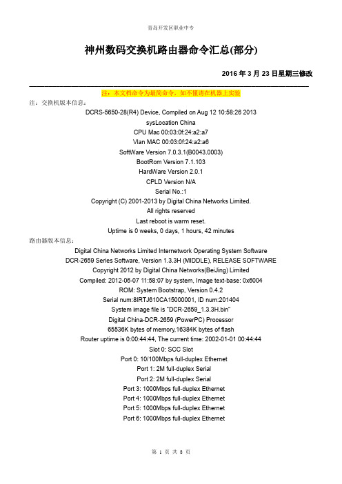
神州数码交换机路由器命令汇总(部分)2016年3月23日星期三修改_________________________________________________________________________注:本文档命令为最简命令,如不懂请在机器上实验注:交换机版本信息:DCRS-5650-28(R4) Device, Compiled on Aug 12 10:58:26 2013sysLocation ChinaCPU Mac 00:03:0f:24:a2:a7Vlan MAC 00:03:0f:24:a2:a6SoftWare Version 7.0.3.1(B0043.0003)BootRom Version 7.1.103HardWare Version 2.0.1CPLD Version N/ASerial No.:1Copyright (C) 2001-2013 by Digital China Networks Limited.All rights reservedLast reboot is warm reset.Uptime is 0 weeks, 0 days, 1 hours, 42 minutes路由器版本信息:Digital China Networks Limited Internetwork Operating System SoftwareDCR-2659 Series Software, Version 1.3.3H (MIDDLE), RELEASE SOFTWARECopyright 2012 by Digital China Networks(BeiJing) LimitedCompiled: 2012-06-07 11:58:07 by system, Image text-base: 0x6004ROM: System Bootstrap, Version 0.4.2Serial num:8IRTJ610CA15000001, ID num:201404System image file is "DCR-2659_1.3.3H.bin"Digital China-DCR-2659 (PowerPC) Processor65536K bytes of memory,16384K bytes of flashRouter uptime is 0:00:44:44, The current time: 2002-01-01 00:44:44Slot 0: SCC SlotPort 0: 10/100Mbps full-duplex EthernetPort 1: 2M full-duplex SerialPort 2: 2M full-duplex SerialPort 3: 1000Mbps full-duplex EthernetPort 4: 1000Mbps full-duplex EthernetPort 5: 1000Mbps full-duplex EthernetPort 6: 1000Mbps full-duplex Ethernet一、交换机配置命令1.基本配置switch > en (enable )进入特权用户模式 switch # con (config) 进入全局配置模式switch (config)# ho switch (hostname) 配置交换机名称 switch (config)# in e1/0/1 进入接口配置模式 switch (config -if -ethernet1/0/1)# exswitch (config)# in vl 1 进入VLAN 配置模式switch (config -if -vlan1)# ip ad 192.168.1.252 255.255.255.0 switch (config -if -vlan1)# exswitch (config)# ena p 1234 配置交换机密码(不加密) switch (config)# ena p 7 1234 配置交换机密码(加密) switch (config)# vl 10 创建vlan switch (config -vlan10)#ex switch (config)# in vl 10switch (config -if -vlan10)# ip ad 172.16.10.1 255.255.255.0 配置VLAN 地址2.生成树技术switch (config)# sp (spanning -tree) 启用全局生成树(默认mstp 生成树技术) switch (config)# sp mo stp/rstp /mstp (生成树/快速生成树/多生成树技术) switch (config)# sp ms 0 p 4096 设置交换机的优先级 默认32768 switch (config)# sh sp (show spanning -tree) 查看生成树3.交换机Web 管理switch (config)# ip ht serswitch (config)# usern admin pa 1234 用户名和密码4.交换机Telnet 管理switch (config)# telnet -s e (telnet enable) 开启telnet 服务 switch (config)# usern admin pa 1234 用户名和密码5.链路聚合(不需启动生成树)switchA (config)# port -g 1 (prot -group) switchA (config)# in e1/0/1-2switchA (config -port -range)# po 1 m on/active switchA (config -port -range)# ex switchA (config)# no port -g 1 删除组1switchB (config)# port -g 2 switchB (config)# in e1/0/3-4switchB (config -port -range)# po 2 m on/active switchB (config -port -range)# ex switchB (config)# no port -g 2 删除组26.交换机MAC 与IP 绑定switch (config)# am e (am enable) 启用全局am 功能 switch (config)# in e1/0/1switch (config_if_ethernet1/0/1)# am p (am port) 打开端口am 功能switch (config_if_ethernet1/0/1)# am m (mac -ip -pool) 00-A0-D1-D1-07-FF 192.168.1.101 switch (config_if_ethernet1/0/1)# ex switch (config)# in e1/0/2输入这条命令会出现: Invalid ENCRYPTED password! Please input the ENCRYPTED password with length 32 密码位数不够32位switch (config_if_ethernet1/0/2)# no am p 解锁端口7.交换机MAC与IP绑定静态绑定switch (config)# in e1/0/1switch (config_if_ethernet1/0/1)# sw p (port-security) 开启绑定功能switch (config_if_ethernet1/0/1)# sw p mac 00-a0-d1- d1-07-ff 添加静态MAC地址switch (config_if_ethernet1/0/1)# sw p max 4 绑定MAC地址的个数(默认为1)动态绑定(实验中交换机没有动态绑定命令)switch (config)# in e1/0/1switch (config_if_ethernet1/0/1)# sw p (port-security) 开启绑定功能switch (config_if_ethernet1/0/1)# sw port-security lockswitch (config_if_ethernet1/0/1)# sw port-security convert 将动态学习到绑定MAC的进行绑定switch # sh port-s add 查看绑定的地址8.交换机DHCP服务器配置switch (config)# service dhcp 启用DHCPswitch (config)# ip dh po poolA定义地址池poolAswitch (dhcp-poolA- config)# netw (network-address) 192.168.1.0 24switch (dhcp-poolA- config)# de (default-router) 192.168.1.254网关switch (dhcp-poolA- config)# dn 60.191.244.5DNS服务器switch (dhcp-poolA- config)# le 3租期3天switch (dhcp-poolA- config)# exswitch (config)# ip dh ex (excluded-add) 192.168.1.252 192.168.1.254 排除地址范围9.保留地址(一个地址池中只能配一个IP-MAC的绑定)switch (config)# ip dh po poolCswitch (dhcp-poolC- config)# ho 192.168.1.100 绑定的IP地址switch (dhcp-poolC- config)# ha (hardware-add) 00-a0-d1- d1-07-ff 绑定的MAC地址switch (dhcp-poolC- config)# de 192.168.1.254 网关10.ACL访问控制列表switchA (config)# ip ac s (standard) test命名标准IP访问列表switchA (config-std-nacl-test)# d (deny) 192.168.100.0 0.0.0.255反子网掩码(路由器上为子网掩码)switchA (config-std-nacl-test)# d 192.168.200.0 0.0.0.255switchA (config-std-nacl-test)# p (permit) a (permit any) 允许所有switchA (config-std-nacl-test)# exswitchA (config)# fir e (firewall enable) 开启ACL功能switchA (config)# in e1/0/1switchA (config-if-interface1/0/1)# ip ac (access-group) test in/out 进in出out (二层交换机上不支持out)11.配置时间范围switchA (config)# time-r worktimeswitchA (config-time-range)# p (periodic) weekd 9:0:0 to 18:0:012.VRRP虚拟路由器冗余协议Master BackupswitchA (config)# router v 1 switchB (config_router)# router v 1switchA (config_router)# v (virtual-ip) 192.168.1.254 switchB (config_router)# v 192.168.1.254 switchA (config_router)# i v 1 (interface vlan 1) switchB (config_router)# i v 1switchA (config_router)# pri 110 switchB (config_router)# enaswitchA (config_router)# c (circuit-failover) v 10 20switchA (config_router)# ena13.DHCP中继DHCP_relay (config)# service dhcp 全局开启DHCP服务DHCP_relay (config)# ip fo u b (ip forward-protocol udp bootps) 全局开启转发DHCP_relay (config)# in vl 10DHCP_relay (config-if-vlan10)# ip h 172.16.1.1 转发到DHCP服务器地址14.DHCP侦听DHCP (config)# service dhcpDHCP (config)# ip dh sn e 开启DHCP侦听功能DHCP (config)# in e1/0/1DHCP (config-if-ethernet1/0/1)# ip d s t (ip dhcp snooping trust)设置上联口为信任口15.端口隔离Switch (config)# is g test s i e1/0/1-2 (isolate-port group test switchport interface e1/0/1-2)e1/0/1-2口不能互相通信,可以和其它端口通信。
神州数码路由器及交换机配置命令

神州数码交换机配置命令交换机基本状态:hostname> ;用户模式hostname# ;特权模式hostname(config)# ;全局配置模式hostname(config-if)# ;接口状态交换机口令设置:switch>enable ;进入特权模式switch#config terminal ;进入全局配置模式switch(config)#hostname ;设置交换机的主机名switch(config)#enable secret xxx ;设置特权加密口令switch(config)#enable password xxa ;设置特权非密口令switch(config)#line console 0 ;进入控制台口switch(config-line)#line vty 0 4 ;进入虚拟终端switch(config-line)#login ;允许登录switch(config-line)#password xx ;设置登录口令xxswitch#exit ;返回命令交换机VLAN设置:switch#vlan database ;进入VLAN设置switch(vlan)#vlan 2 ;建VLAN 2switch(vlan)#no vlan 2 ;删vlan 2switch(config)#int f0/1 ;进入端口1switch(config-if)#switchport access vlan 2 ;当前端口加入vlan 2switch(config-if)#switchport mode trunk ;设置为干线switch(config-if)#switchport trunk allowed vlan 1,2 ;设置允许的vlan switch(config-if)#switchport trunk encap dot1q ;设置vlan 中继switch(config)#vtp domain ;设置发vtp域名switch(config)#vtp password ;设置发vtp密码switch(config)#vtp mode server ;设置发vtp模式switch(config)#vtp mode client ;设置发vtp模式交换机设置IP地址:switch(config)#interface vlan 1 ;进入vlan 1switch(config-if)#ip address ;设置IP地址switch(config)#ip default-gateway ;设置默认网关switch#dir Flash: ;查看闪存交换机显示命令:switch#write ;保存配置信息switch#show vtp ;查看vtp配置信息switch#show run ;查看当前配置信息switch#show vlan ;查看vlan配置信息switch#show interface ;查看端口信息switch#show int f0/0 ;查看指定端口信息完了最最要的一步。
神州数码交换机路由器常用命令操作
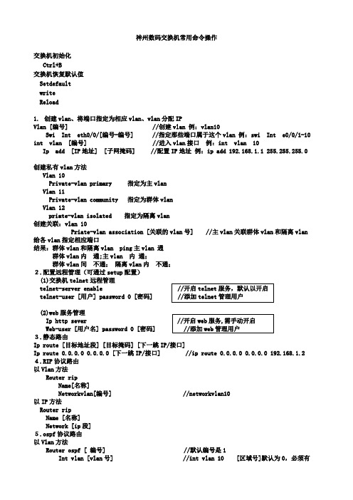
神州数码交换机常用命令操作交换机初始化Ctrl+B交换机恢复默认值SetdefaultwriteReload1.创建vlan、将端口指定为相应vlan、vlan分配IPVlan [编号] //创建vlan 例:vlan10Swi Int eth0/0/[编号-编号] //指定那些端口属于这个vlan 例:swi Int e0/0/1-10 int vlan [编号] //进入vlan接口例:int vlan 10 Ip add [IP地址] [子网掩码] //配置IP地址例:ip add 192.168.1.1 255.255.255.0创建私有vlan方法Vlan 10Private-vlan primary 指定为主vlanVlan 11Private-vlan community 指定为群体vlanVlan 12priate-vlan isolated 指定为隔离vlan创建关联:vlan 10Priate-vlan association [关联的vlan号] //主vlan关联群体vlan和隔离vlan 给各vlan指定相应端口结果:群体vlan和隔离vlan ping主vlan 通群体vlan内通;主vlan 内通;群体vlan间不通;隔离vlan内不通;2.配置远程管理(可通过setup配置)(1)交换机telnet远程管理telnet-server enable //开启telnet服务,默认以开启telnet-user [用户] password 0 [密码] //添加telnet管理用户(2)web服务管理Ip http sever //开启web服务,需手动开启Web-user [用户名] password 0 [密码] //添加web管理用户3.静态路由Ip route [目标地址段] [目标掩码] [下一跳IP/接口]Ip route 0.0.0.0 0.0.0.0 [下一跳IP/接口] //ip route 0.0.0.0 0.0.0.0 192.168.1.2 4.RIP协议路由以Vlan方法Router ripName[名称]Networkvlan[编号] //networkvlan10以IP方法Router ripName [名称]Network [ip段]5.ospf协议路由以Vlan方法Router ospf [ 编号] //默认编号是1Int vlan [vlan号] //int vlan 10 [区域号]默认为0,必须有Ip ospf enable area [区域号] //ip ospf enable area 0以IP方法Router ospf [ 编号]Router-id [ip地址]Network [自己的IP] [网关] area 0 //network 192.168.1.1/24 area 0 6.生成树协议1)Stp模式配置spanning-tree //启用生成树spanning-tree mode stp //设置生成树模式spanning-tree mst 0 priority 4096 //设置生成树交换机优先级2)mstp的配置spanning-treespanning-tree mst configurationname [名称]instance [实例号] vlan [编号]spanning-tree mst [实例号] priority 4096 //设置生成树交换机优先级spanning-tree mst [实例号] port-priority 16 //设置生成树端口优先级3)配置成快速启用端口Int e0/0/[编号-编号]Spanning-tree portfast7.链路聚合(手工)port-group [组号] //创建聚合组号int e0/0/[做链路的那几个端口号] //将端口加入聚合组port-group [组号] mode on8.链路聚合(LACP动态生成)port-group [组号]int e0/0/[做链路的那几个端口号](交换机A的配置)port-group [组号] mode active(交换机B的配置)port-group [组号] mode passive9.trunkInt e0/0/[端口]Sw mode trunk //设置为trunkSw trunk allowed vlan all //划分到所有vlan10.Mac地址和端口绑定(单个)Int e0/0/[端口]Sw port-securitySw port-security mac-address [mac地址]11.Mac地址和端口绑定(多个)Inte0/0/[端口]Sw port-securitySw port-security maximum [安全mac地址个数如:3]sw port-security mac-address [mac地址]sw port-security mac-address [mac地址]sw port-security mac-address [mac地址]12.Mac地址和端口绑定(动态学习)Int e0/0/[端口]Sw port-security maximumSw port-security maximum lockSw port-security maximum convert13.mac地址表绑定mac-address-table static address[mac地址]vlan[编号]inte0/0/[编号]//解释:让mac地址只能在指定vlan中的指定端口中使用,其他的都不能使用(未测试) 14. 端口安全1) int e0/0/1-10 //进入端口,只能在access口上配置2) switchport port-security //开启端口安全功能3) switchport port-security maximum 5 //配置端口安全最大连接数4) sw port-security violation shutdown //配置违例处理方式5).sw port-security mac-address [mac地址] //配置mac地址绑定15. 交换机端口镜像(将源端口数据复制到目标端口)1) monitor session 1 source interface fastEthernet 0/2 both //源端口、被镜像的端口2) monitor session 1 destiNation interface fastEthernet 0/3 //目标端口、镜像端口16.dhcp配置1)交换机做dhcp服务器配置Service dhcp //启用DHCP服务Ip dhcp pool [地址池名]Network-address [IP段如:192.168.1.0] [掩码数如:24]Lease[租用天数]Default-router[网关IP]Dns-server[DNS的IP]Ip dhcp excluded-address<开始地址><结束地址>//指定网段中不分配的IP地址2)Dhcp中继服务的配置Service dhcpIp forward-protocol udp bootps //配置DHCP中继转发port端口的UDP广播报文,默认67端口Int vlan [编号]或在接口上配置 //int e0/0/[编号]Ip help-address [服务器IP] //指定DHCP中继转发的UDP报文的目标地址17.ACL IP访问控制下面2条是开启ACLFirewall enable //开启包过滤功能Firewall default permit //设置默认动作为允许//定义标准访问控制列表 //定义访问列表Ip access-list standard test //在端口上应用列表Deny 192.168.1.100.00.0.0.0.255//禁止IP段访问Deny 192.168.200.11 0.0.0.0//禁止单个IP访问Denytcp192.168.200.00.0.0.255any-destinationd-port23//拒绝IP段telnet数据Permit192.168.1.100.00.0.0.0.255//允许IP段访问Deny192.168.200.110.0.0.0//允许IP访问//绑定ACL到各个端口Inte0/0/[端口]Ip access-group test in//验证方法Show access-group标准ACL实验1) access-list 1 deny 192.168.1.0 0.0.0.255 //拒绝访问的IP段2) access-list 1 permit 192.168.1.0 0.0.0.255 //允许的IP段3) //进入端口4) ip access-group 1 in //把控制列表1 配入端口,进入控制5) ip access-group 1 out //把控制列表1 配入端口,输出控制15. 扩展ACL实验1) access-list 101 deny tcp A.B.C.D 255.255.255.0 A.B.C.D 255.255.255.0 eq ftp(WWW)// 禁止前面个网段访问后面个网段的ftp或者WWW16. 交换机单向访问控制1) //使用标准ACL2) access-list 1 deny 192.168.1.0 0.0.0.2553) //进入端口4) ip access-group 1 in神州数码路由器常用命令操作路由器初始化:ctrl+breakNopassword路由器恢复默认值dirDel startup-configReboot1.进入端口给端口分配IPInt [端口]Ip add [ip] [子网掩码]No shuFC串口配置时钟频率Ph sp 640002.静态路由Ip route [目标地址段] [目标掩码] [下一跳IP/接口]Ip route 0.0.0.0 0.0.0.0 [下一跳IP/接口] //默认路由Ip route 0.0.0.0 0.0.0.0 [下一跳IP/接口] 10 //浮动路由3.RIP协议路由Router ripNetwork [ip段]4.ospf协议路由Router ospf [进程号]Router-id [ip地址]Network [自己的IP段] [子网掩码] area [区域号如:0]5.telnet开启方法1Aaa authen enable default lineAaa authen login default lineEnable passwd [密码]Line vty 0 4Password [密码]方法2Username [用户名] password [密码]Aaa authentication login [用户名] localLine vty 0 4Login authentication [刚刚那个用户名]6.web访问配置Username [用户] password 0 [密码] //添加用户Ip http webm-type[web配置方式] //选择方式.高级,典型,向导Ip http port[端口] //配置web端口7.ppp协议时钟频率physical-layer speed 64000封装PPP协议Int s0/[编号]Enc ppp //封装PPP协议单向验证(验证方式为PAP和CHAP)验证方Aaa authen ppp default localUsername [用户名] password [密码]Int s0/[编号]Enc pppPpp authen pap被验证方Aaa authen ppp default localInt s0/[编号]Enc pppPpp pap sen [用户名] passwd [密码]双向验证:9.hdlcInt s0/[编号]Enc hdlc //和PPP差不多,都在端口中配置10.dhcp配置Ip dhcp pool[地址池名]Network 192.168.2.0 255.255.255.0 //定义网络段Range 192.168.2.10 192.168.2.20 //定义地址范围Default-router [IP] //配置网关Dns-sever [ip] //配置NDS的IPLease [天数] //租用天数//退回配置模式(config)Ip dhcpd enable//开启dhcp11.Nat网络地址转换分为三种静态地址转换、动态地址转换、端口复用第一种1对1的网络地址转换,也叫静态地址转换,主要用于发布服务器(FTP/WEB/telnet)1)定义内外口在端口下输入ip nat inside ip nat outside2)配置地址转换:ip nat inside source static <服务器地址> <公网地址>ip nat inside source static tcp <服务器地址> 80 <公网地址> 80 发布WWW服务ip nat inside source static tcp <服务器地址> 20 <公网地址> 20 发布ftp服务ip nat inside source static tcp <服务器地址> 21 <公网地址> 21ip nat inside source static tcp <服务器地址> 23 <公网地址> 23 允许telnet远程登陆第二种多对多的网络地址转换,也叫动态地址转换1)定义内外口在端口下输入ip nat inside ip nat outside2)定义内网访问列表(标准)和外网的地址池定义内网访问列表:ip access-list standard <列表名>permit <vlan段> <反掩码> //定义允许转换的源地址范围定义外网的地址池:ip nat pool <地址池名> <外网开始地址> <外网结束地址> netmask <子网掩码> 3)配置地址转换:ip nat inside source list <列表名> pool <地址池名> overload第三种多对一的网络地址转换,也叫端口复用(natp)1)定义内外口在端口下输入ip nat inside ip nat outside2)定义内网访问列表定义内网访问列表:ip access-list standard <列表名>permit <vlan段> <反掩码>3)配置地址转换:ip nat inside source list <列表名> interface <外网接口编号> overload12.vpn(L2TP/PPTP)的配置//A到B的数据传输实例ROUTER-A的配置Intvirtual-tunnel0Ipadd172.16.1.2255.255.255.0***********************Pppchappassword[密码]//退回配置模式(config)VpdnenableVpdn-group0Request-dialinInitiate-toip192.168.1.2priority1Protocol12tp//退回配置模式(config)Iproute192.168.2.0255.255.255.0virtual-tunel0ROUTER-B的配置13、路由重分布redistribute static 重分布静态路由default-information originate 重分布默认路由redistribute connect 重分布直连网段redistribute rip 重分布RIP路由redistribute ospf <进程号> 重分布OSPF路由default-metric [权值] 设置路由权值14、策略路由1)定义内网访问列表:ip access-list standard <列表名>permit <vlan段> <反掩码>2)定义路由图route-map <图名> <图号1> permit/denymatch ip address <列表名>set ip next-hop <ip-address> 设置下一跳地址或 set interface fastethernet < > 设置出口route-map <图名> <图号2> permit/denymatch ip address <列表名>set ip next-hop <ip-address> 设置下一跳地址或 set interface fastethernet < > 设置出口3)在指定路由器的入口上应用路由图Router(config-if)#ip policy route-map <图名>15、Rip 认证:在端口上进行认证(要求在两台设备的路由端口配置)RIP版本1不支持认证。
神州数码网络设备配置命令集合

网路信息安全技能大赛网络搭建部分资料整理第一部分:交换机配置:1.基本配置:开启SSH服务:debug ssh-server设置特权模式密码:enable password [8] <password> 注释:8为加密的密码设置退出特权模式超时时间::exec-timeout <minutes > [<seconds>]Switch(config)#exec-timeout 5 30(退出时间为5分30秒)更改主机名:hostname 主机名设置主机名与IP地址的映射关系:Switch(config)#ip host beijing 200.121.1.1(beijing为主机)开启web配置服务:Switch(config)#ip http serve显示帮户信息的语言类型:language {chinese|english}使用密码验证:login使用本地用户密码验证:Switch(config)#login local设置用户在console上进入一般用户配置模式时的口令:Switch(config)#password 8 test热启动交换机:reload加密系统密码:service password-encryption恢复交换机出厂配置:set default保存当前配置:write配置交换机作为Telnet 服务器允许登录的Telnet 客户端的安全IP 地址:Switch(config)#telnet-server securityip 192.168.1.21设置Telnet 客户端的用户名及口令:Switch(config)#telnet-user Antony password 0 switch打开交换机的SSH服务器功能:Switch(config)#ssh-server enable设置SSH客户端的用户名及口令:Switch(config)#ssh-user switch password 0 switch通过DHCP 方式获取IP 地址。
神州数码命令总结
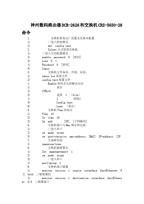
神州数码路由器DCR-2626和交换机CRS-5650-28命令1. 交换机恢复出厂设置及其基本配置.1) //进入特权模式2) del config.text2. Telnet方式管理交换机.1) //进入全局配置模式2) enable password 0 [密码]3) Line 0 44) Password 0 [密码]5) Login3. 交换机文件备份、升级、还原。
1) rgnos.bin系统文件2) config.text配置文件4. Enable密码丢失的解决办法1) 重启2) CTRL+C3) 选择 4 (file)4) 1 (移除)5) Config.text6) Load (重启)5. 交换机Vlan的划分1) Vlan 102) In vlan 103) Ip add [IP] [子网掩码]6. 交换机端口与Mac绑定和过滤1) //进入串口2) sw mode trunk3) sw port-security mac-address [MAC] IP-address [IP7. 生成树实验1) spanning-tree8. 交换机链路聚合1) Int aggregateport 12) sw mode trunk3) //进入串口4) port-group 19. 交换机端口镜像1) monitor session 1 source interface fastEthernet 0/2 both //被镜像的2) monitor session 1 destination interface fastEthernet 0/3 //镜像端口10. 多层交换机静态路由实验1) ip route [存在的IP段] [子网掩码] [下一跳IP]11. RIP动态路由1) router rip2) version 23) network [IP段]4) no auto-summary12. 端口安全1) //进入端口2) switchport port-security //开启端口安全3) switchport port-security maximum 5 //最大连接5.4) sw port-security violation shutdown //超出就shudown13. OSPF动态路由1) router ospf2) network [IP段] [反码] area 014. 标准ACL实验1) access-list 1 deny 192.168.1.0 0.0.0.255 //拒绝访问的IP段2) access-list 1 permit 192.168.1.0 0.0.0.255 //允许的IP段3) //进入端口4) ip access-group 1 in //把控制列表 1 配入端口,进入控制5) ip access-group 1 out //把控制列表 1 配入端口,输出控制15. 扩展ACL实验1) access-list 101 deny tcp A.B.C.D 255.255.255.0 A.B.C.D 255 .255.255.0 eq ftp(WWW)// 禁止前面个网段访问后面个网段的FTP或者WWW16. 交换机单向访问控制1) //使用标准ACL2) access-list 1 deny 192.168.1.0 0.0.0.2553) //进入端口4) ip access-group 1 in17. 交换机DHCP服务器配置1) service dhcp2) ip dhcp ping packets 13) ip dhcp excluded-address [ip1] [IP 2] //设置排斥的IP地址从1到2开始4) ip dhcp pool [名字]5) lease infinite //永久租用6) network [IP段] [子网掩码]7) default-router [网关IP]8) dns-server [NDS IP]18. 交换机DHCP中继功能1) service dhcp2) //进入VLAN3) ip helper-address [DHCP的网管]19. 交换机VRRP实验1) //进入VLAN2) vrrp 10 ip [IP] //设置vrrp虚拟网关3) vrrp 10 priority 150 //设置优先级为150(默认100)20. 交换机QOS实验 car1) //1.扩展控制列表,2策略,3方法 4配入端口2) access-list 101 permit ip host A.B.C.D any //定义要限速的IP3) class-map xiansu1 //创建class-map 名字为xiansu14) match access-group 101 //把控制列表套入策略xiansu15) policy-map pozz 创建policy-map名字为pozz6) class xiansu17) police 8000 512 exceed-action drop //限速值为8000 kbit ,512KB8) //进入端口9) service-policy input pozz路由器要求1. 路由器telneta) //进入全局配置模式b)c) enable password 0 [密码]d) Line vty 0 4e) Password 0 [密码]2. Login路由器weba) //先建立用户密码b) Ip http port 80 //开启web端口为803. 路由器广域网HDLC封装配置a) encapsulation hdlc4. 路由器广域网PPP封装配置a) encapsulation ppp5. 路由器广域网PPP封装PAP配置a) encapsulation pppb) ppp authentication papc) ppp pap sent-username [用户] password 0 [密码] //验证方d) username [用户名] password 0 [密码] //被验证方6. 路由器广域网PPP封装CHAP配置a) encapsulation pppb) ppp authentication CHAP7. ppp chap hostname [对方电脑]8. ppp chap password 0 12345687a) Ip nat Inside 设置为内网接口b) ip nat outside 设置为外网接口c) access-list 10 permit A.B.C.D 0.0.0.255//配置允许访问的ACLd) ip nat inside source list 10 interface serial 1/0 overl oad //允许访问外网的ACL9. NAT内网映射a) ip nat inside source static tcp 192.168.1.1 80 interfac e s4/0 //把IP的80端口射到s4/0端口10. 策略路由(PBR)配置Access-list 101 permit ip host A.B.C.D any //定义ACLRoute-map test permit 10 ..\\定义策略Match ip add0020101 .//匹配ACLSet int null 0//如果匹配就丢弃Set ip next-hop A.B.C.D //如果匹配就放到下一条Route-map test permit 20 //如果不匹配执行默认路由Int f 0/1 //进入端口Ip policy route-map test //关联策略11. 路由在发布a) 当出现多动态路由的时候,一个网段只声明一次,要和下一条的协议一样b) Reredistribute rip subnets 重分布RIP路由redistribute static subnets 重分布静态路由5650S-1(config)#router rip5650S-1(config-router)#version 25650S-1(config-router)#redistribute ospf5650S-1(config-router)#redistribute stati12. 配置QOSa) //1.扩展控制列表,2策略,3方法 4配入端口b) access-list 101 permit ip host A.B.C.D any //定义要限速的IPc) class-map xiansu1 //创建class-map 名字为xiansu1d) match access-group 101 //把控制列表套入策略xiansu1e) policy-map pozz 创建policy-map名字为pozzf) class xiansu1g) police 8000 512 exceed-action drop //限速值为8000 kbit ,512KBh) //进入端口i) service-policy input pozz13. VPN,pptpa) ip local pool text 192.168.2.2 192.168.2.20 //定义获取VPN的地址池,b) interface Virtual-Template 1 //进入虚接口1c) ppp authentication pap //配置认证方式d) ip unnumbered FastEthernet 1/0 //继承接口IPe) peer default ip address pool pptp //关联地址池f) //进入全局模式g) vpdn enable //开启VPNh) vpdn-group PPTP //定义组名称i) accept-dialin //允许拨入访问j) protocol pptp //允许拨入访问得协议k) virtual-template 1 //关联虚接口,拨入时候分配给用户得虚接口。
神州数码配置命令
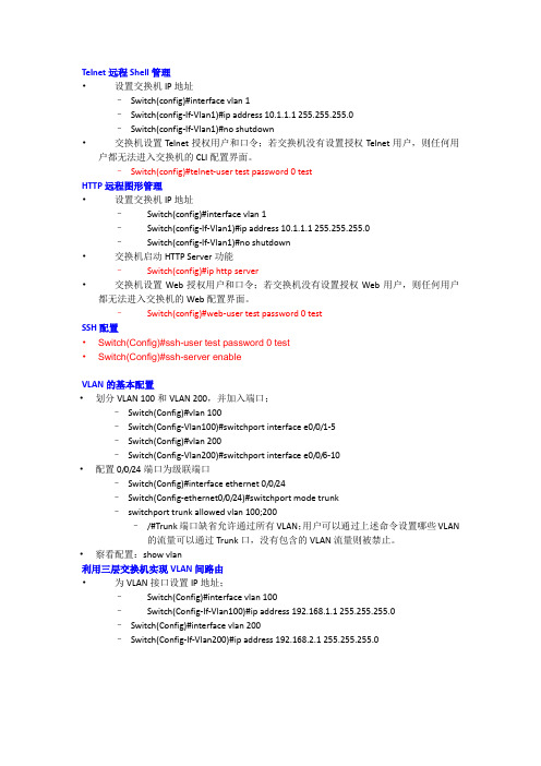
Telnet远程Shell管理•设置交换机IP地址–Switch(config)#interface vlan 1–Switch(config-If-Vlan1)#ip address 10.1.1.1 255.255.255.0–Switch(config-If-Vlan1)#no shutdown•交换机设置Telnet授权用户和口令;若交换机没有设置授权Telnet用户,则任何用户都无法进入交换机的CLI配置界面。
–Switch(config)#telnet-user test password 0 testHTTP远程图形管理•设置交换机IP地址–Switch(config)#interface vlan 1–Switch(config-If-Vlan1)#ip address 10.1.1.1 255.255.255.0–Switch(config-If-Vlan1)#no shutdown•交换机启动HTTP Server功能–Switch(config)#ip http server•交换机设置Web授权用户和口令;若交换机没有设置授权Web用户,则任何用户都无法进入交换机的Web配置界面。
–Switch(config)#web-user test password 0 testSSH配置•Switch(Config)#ssh-user test password 0 test•Switch(Config)#ssh-server enableVLAN的基本配置•划分VLAN 100和VLAN 200,并加入端口;–Switch(Config)#vlan 100–Switch(Config-Vlan100)#switchport interface e0/0/1-5–Switch(Config)#vlan 200–Switch(Config-Vlan200)#switchport interface e0/0/6-10•配置0/0/24端口为级联端口–Switch(Config)#interface ethernet 0/0/24–Switch(Config-ethernet0/0/24)#switchport mode trunk–switchport trunk allowed vlan 100;200–/#Trunk端口缺省允许通过所有VLAN;用户可以通过上述命令设置哪些VLAN 的流量可以通过Trunk口,没有包含的VLAN流量则被禁止。
神州数码配置命令

第一部分交换机配置一、基础配置1、模式进入Switch>Switch>enSwitch#configSwitch(Config)#interface ethernet 0/22、配置交换机主机名命令:hostname <主机名>3、配置交换机IP地址Switch(Config)#interface vlan 1Switch(Config-If-Vlan1)#ip address 10.1.128.251 255.255.255.0Switch(Config-If-Vlan1)#no shut4、为交换机设置Telnet授权用户和口令:登录到Telnet的配置界面,需要输入正确的用户名和口令,否则交换机将拒绝该Telnet用户的访问。
该项措施是为了保护交换机免受非授权用户的非法操作。
若交换机没有设置授权Telnet用户,则任何用户都无法进入交换机的Telnet配置界面。
因此在允许Telnet方式配置管理交换机时,必须在Console的全局配置模式下使用命令username privilege [password (0 | 7) ]为交换机设置Telnet授权用户和口令并使用命令authentication line vty login local打开本地验证方式,其中privilege选项必须存在且为15。
例:Switch>enableSwitch#configSwitch(config)#username test privilege 15 password 0 testSwitch(config)#authentication line vty login localSwitch(Config)#telnet-user test password 0 testSwitch (Config)#telnet-server enable://启动远程服务功能5、配置允许Telnet管理交换机的地址限制(单独IP或IP地址段)(1)限制单个IP允许Telnet登录交换机switch(config)#authentication security ip 192.168.1.2(2)限制允许IP地址段Telnet登录交换机switch(config)#access-list 1 permit 192.168.1.0 0.0.0.255switch(config)#authentication ip access-class 1 in5、为交换机设置Web授权用户和口令:web-user <用户名>password {0|7} <密码>例:Switch(Config)#web-user admin password 0 digital6、设置系统日期和时钟:clock set7、设置退出特权用户配置模式超时时间exec timeout //单位为分钟,取值范围为0~3008、保存配置:write9、显示系统当前的时钟:Switch#show clock10、指定登录用户的身份是管理级还是访问级Enable [level {visitor|admin} [<密码>]]11、指定登录配置模式的密码:Enable password level {visitor|admin}12、配置交换机的用户名密码:username admin privilege 15 password 0 admin00013、配置enable密码为ddd:enable password 0 ddd level 1514、配置登录时认证:authentication line vty login local15、设置端口的速率和双工模式(接口配置模式下)命令:speed-duplex {auto | force10-half | force10-full | force100-half | force100-full |{{force1g-half | force1g-full} [nonegotiate [master | slave]] } }no speed-duplex二、单交换机VLAN划分1、VLAN基本配置(1)新建VLAN:vlan(2)命名VLAN:name(3)为VLAN 分配交换机端口Switch(Config-If-Vlan1)#switchport interface Ethernet 0/2(4)设置Trunk 端口允许通过VLAN:Switch(Config-ethernet0/0/5)#switchport trunk allowed vlan 1;3;5-202、划分VLAN:(1)进入相应端口:Switch(config)#interface Ethernet 0/2(2)修改模式:Switch(Config-ethernet0/0/5)switchport mode access (3)划分VLAN:Switch(Config-ethernet0/0/5)#switchport access vlan 4三、跨交换机VLAN划分(两台交换机作相同操作)1、新建VLAN2、划分VLAN3、修改链路模式(1)进入相应端口:Switch(config)#interface Ethernet 0/1(2)修改模式:Switch(config-if)#switchport mode trunk四、VLAN间主机的通信1、新建VLAN2、划分VLAN3、修改链路模式(1)进入相应端口:Switch(config)#interface Ethernet 0/1(2)修改模式:Switch(config-if)#switchport mode trunk注意:如果是三层交换机,在修改模式先封装802.1协议:Switch(config-if)#switchport trunk encapsulation dot1q4、建立VLAN子接口(1)、进入VLAN接口模式:Switch(config)#interface vlan 2(2)、设置VLAN子接口地址:Switch(config-if)#ip address 192.168.0.1 255.255.255.0 (3)、打开端口:Switch(config-if)#no shutdown5、设置各主机IP地址、子网掩码、网关注意:(1)各主机IP地址应与其所在的VLAN在同一网段。
神州数码交换机路由器常用命令操作
神州数码交换机路由器常用命令操作神州数码交换机常用命令操作(一)交换机1.声明vlan and给vlan分配IPvlan [编号] //vlan 10Sw I e 0/0/[编号-编号] //sw I e 0/0/1-10sin vlan [编号] //in vlan 10ip add [IP地址] [子网掩码] //ip add 192.168.1.1 255.255.255.0 2.静态路由Ip route 0.0.0.0 0.0.0.0 [下一跳IP] //ip route 0.0.0.0 0.0.0.0 192.168.1.2 3.RIP协议路由以Vlan方法Router ripNetwork [自己的vlan ] //network vlan 10 以IP方法Router ripNetwork [ip 段]4.ospf协议路由以Vlan方法Router ospfInt vlan [编号] //int vlan 10Ip ospf enable area [编号] //ip ospf enable area 0 以IP方法Router ospfNetwork [自己的IP]/[网关] area 0 //network 192.168.1.1/24 area 0 5.telnet开启telnet-server enabletelnet-user [用户] password 0 [密码]6.stp生成树协议spanning-tree mode stp7.链路聚合(手工)spanning-tree mode mstp //开启mstp生成树协议port-group [编号] // port-group 1int e 0/0/[做链路的那几个端口号] //int 0/0/1-2port-group [编号] mode on // port-group 1 mode on 8. 链路聚合(LACP动态生成)spanning-tree mode mstpport-group [编号](交换机A的配置)port-group [编号] mode active(交换机B的配置)port-group [编号] mode passive9.trunkInt e 0/0/[端口]Sw mode trunk //设置为trunkSw trunk allowed vlan all //划分到所有vlan 10.Mac地址和端口绑定(单个)Int e 0/0/[端口]Sw port-securitysw port-security mac-address [mac地址]11. Mac地址和端口绑定(多个)Int e 0/0/[端口]Sw port-security maximum [安全mac地址个数如:3]sw port-security mac-address [mac地址]sw port-security mac-address [mac地址]sw port-security mac-address [mac地址]12. Mac地址和端口绑定(动态学习)Int e 0/0/[端口]Sw port-security maximumSw port-security maximum lockSw port-security maximum convert13.mac地址表绑定mac-address-table static address [mac地址] vlan [编号] int e0/0/[编号]//解释: 让mac地址只能在指定vlan中的指定端口中使用,其他的都不能使用(未测试) 14.mac地址过滤mac-address-table blackhole address [mac地址] vlan [编号] //解释: 让mac地址在指定vlan中不能使用(未测试)15.用am来绑定ip和macAm enableInt e 0/0/[端口]Am mac-ip-pool [mac地址] [IP地址]//验证方法: show am//解锁:no am port16.dhcp配置Service dhcpIp dhcp pool [地址池名]Network-address [IP段如:192.168.1.0] [掩码数如:24]Lease [租用天数]Default-router [网关IP]Dns-server [DNS 的IP]17.ACL IP访问控制Ip access-list standard testDeny 192.168.1.100.0 0.0.0.0.255 //禁止IP段访问Deny 192.168.200.11 0.0.0.0 //禁止单个IP访问Deny tcp 192.168.200.0 0.0.0.255 any-destination d-port 23 //拒绝IP段telnet数据Permit 192.168.1.100.0 0.0.0.0.255 //允许IP段访问Deny 192.168.200.11 0.0.0.0 //允许IP访问//下面2条是开启ACLFirewall enableFirewall default permit//绑定ACL到各个端口Int e 0/0/[端口]Ip access-group test in//验证方法Show access-group18. web管理Ip http sever //开启web服务Web-user [用户名] password 0 [密码] //添加管理用户神州数码路由器常用命令操作(二)路由器1. 进入端口给端口分配IPa) Int [段口]b) Ip add [ip] [子网掩码]c) No shu2.静态路由Ip route 0.0.0.0 0.0.0.0 [下一跳IP] //ip route 0.0.0.0 0.0.0.0 192.168.1.2 3.RIP协议路由Router ripNetwork [ip 段]4.ospf协议路由Router ospf [进程号如:1]Network [自己的IP段] [子网掩码] area [区域号如:0]5.telnet开启Username [用户名] password [密码]Aaa authentication login [用户名] localLine vty 0 4Login authentication [刚刚那个用户名]6.ppp协议Enc ppp7.时钟平率Ph sp 640008.web访问Username [用户] password 0 [密码] //添加用户ip http webm-type [web配置方式] //选择方式.高级,典型,向导ip http port [端口] //配置web端口9.hdlc//和PPP差不多,都在端口中配置Enc hdlc10.dhcpIp dhcp pool [地址池名如:1]Network 192.168.2.0 255.255.255.0 //定义网络段Range 192.168.2.10 192.168.2.20 //定义地址范围Default-router [IP] //配置网关Dns-sever [ip] //配置NDS的IPLease [天数] //租用天数//退回配置模式(config)Ip dhcpd enable //开启dhcp11.natRouter-A_config#Ip access-list standard [访问控制名如:1] //定义访问控制列表Router-A_config_sta_nacl#Permit [IP 段] [子网掩码] //定义允许转换的源地址范围//如:permit 192.168.10.0 255.255.255.0Router-A_config#ip nat pool [转换地址池名如:xh] [起始IP] [结束IP] [子网掩码]Router-A_config#ip nat inside soure list [刚刚定义的访问控制名] pool [刚刚转换地址池名] overload //配置将ACL允许的源地址转换成overld 中的地址,并且做pat复用地址Router-A_config#int f0/0Router-A_config_f0/0#ip nat inside //定义内部接口Router-A_config# int s0/2Router-A_config_ s0/2#ip nat outside //定义外部接口12.vpn(L2TP/PPTP)的配置//A到B的数据传输实例ROUTER-A的配置Int virtual-tunnel 0Ip add 172.16.1.2 255.255.255.0Ppp chap host test@/doc/b66269808.html, Ppp chap password [密码]//退回配置模式(config)Vpdn enableVpdn-group 0Request-dialinInitiate-to ip 192.168.1.2 priority 1Protocol 12tpDomain /doc/b66269808.html,//退回配置模式(config)Ip route 192.168.2.0 255.255.255.0 virtual-tunel 0 ROUTER-B的配置。
神州数码-配置

Hostname: HaiNanZFXYS9303:sysname HaiNanZFXY(1)全局配置密码:admingyS9303:super password admingy123(2)用户:zfxygf admingyzfxy adminS9303:aaaLocal-user zfxy password cipher admingyLocal-user zfxy level 3(3)远程登录认证:Radius + Local (Radius server ip 查看?)Authentication Security ip :125.217.112.230192.168.7.248125.217.113.254125.217.112.235125.217.112.227192.168.99.248S9303:radius-server template renzhengradius-serverradius-server shared-keyradius-server retransmit 2aaaauthentication-scheme defaultauthentication-mode radius localauthorization-scheme defaultaccounting-scheme defaultdomain defaultuser-interface vty 0 4authentication-mode aaauser privilege level 3acl 3001rule 0 permit ip source 125.217.112.230 0 destination anyrule 1 permit ip source 192.168.7.248 0 destination anyrule 2 permit ip source 125.217.113.254 0 destination anyrule 3 permit ip source 125.217.112.235 0 destination anyrule 4 permit ip source 125.217.112.227 0 destination anyrule 5 permit ip source 192.168.99.248 0 destination anyrule 6 deny ip source any destination anyuser-interface vty 0 4acl 3001 inboundacl 3001 outbound(4)dhcp server:转发udp bootp 协议Help ip 125.217.112.235S9303:Dhcp enabledhcp server group dhcprelaydhcp-server 125.217.112.235(5)Firewall:启用(6)VLAN:Vlan 1Vlan 10Vlan 13Vlan 16Vlan 17Vlan 18Vlan 19Vlan 20Vlan 22Vlan 25Vlan 26Vlan 27Vlan 28Vlan 48Vlan 49Vlan 70Vlan 200Vlan 222Vlan 254Vlan 2000Vlan 6Description zonghelouVlan 8Description1jiaoxuelouVlan 11Description2jiao6louVlan 12Description peixunlouVlan 21Vlan 23Description8jifang Vlan 24Description9jifang Vlan 30Description internet Vlan 33Description servers Vlan 34Description DMZVlan 38Description15#(1-2)new Vlan 40Description jiaoyuwang Vlan 41Description girlhouse-4 Vlan 42Description girlhouse11 Vlan 43Description boyhouse5 Vlan 44Description boyhouse15 Vlan 45Description15_1-3 Vlan 46Description15_5Vlan 47Description15_6Vlan 50Description shitang Vlan 51Description safeVlan 52Description11#(1-3) Vlan 53Description15#(1-2) Vlan 54Description tushuguan Vlan 55Description16#-1Vlan 56Description16#-2Vlan 57Vlan 58Description16#-4Vlan 59:Description16#-5Vlan 60Description16#-6Vlan 71Description shixunlou-1louVlan 72Description shixunlou-2louVlan 73Description shixunlou-3louVlan 74Description shixunlou-4louVlan 75Description shixunlou-5louVlan 76Description shixunlou-6louVlan 77Description shixunlou-4lou-dianjin Vlan 78Description shixunlou-4lou-zhongxin Vlan 79Description shixunlou-401Vlan 80Description shixunlou-403Vlan 81Description shixunlou-405Vlan 82Description shixunlou-406Vlan 83Description shixunlou-407Vlan 100Description guanlivlanVlan 300Description to16#beiVlan 301Description to15#nanVlan 302Description to11#Vlan 303Description to5#Vlan 304Vlan 500Description jinlongkaVlan 1000Description CRPcuncuVlan 3000Description hnzfwifi(7)ACL:Deny ip any-source 192.168.(21-28,31-38).0 0.0.0.255S9303:rule 5001 deny ip source 10.1.7.0 0.0.0.255 destination 10.1.2.0 0.0.0.255进入端口模式Acl 5001 inboundAcl 5001 outound(8)Port interface:9个千兆口1/1 UP/UP a-100M a-FULL 33 FE netlogguanli 1/2 UP/UP a-100M a-FULL 40 FE jiaoyuwang 1/3 A-DOWN/DOWN auto auto 1 FE1/4 UP/UP a-100M a-FULL 34 FE1/5 UP/UP a-100M a-FULL 34 FE bgwOAserver 1/6 UP/UP a-100M a-FULL 33 FE1/7 DOWN/DOWN auto auto 40 FE1/8 UP/UP a-100M a-FULL 34 FE1/9 UP/UP a-100M a-FULL 34 FE1/10 UP/UP a-100M a-FULL 33 FE1/11 UP/UP a-100M a-FULL 33 FE1/12 UP/UP a-100M a-FULL 33 FE DHCP-SERVER 1/13 UP/UP a-100M a-FULL 33 FE1/14 UP/UP a-100M a-FULL 500 FE1/15 DOWN/DOWN auto auto 500 FE1/16 UP/UP a-100M a-FULL 33 FE1/17 UP/UP a-100M a-FULL 34 FE1/18 UP/UP a-100M a-FULL 33 FE1/19 UP/UP a-100M a-FULL trunk FE1/20 UP/UP a-100M a-FULL 34 FE1/21 UP/UP a-100M a-FULL 33 FE1/22 DOWN/DOWN auto auto 33 FE1/23 UP/UP a-100M a-FULL 33 FE1/24 DOWN/DOWN auto auto 54 FE1/25 UP/UP a-1G a-FULL 30 G-Combo:Copper dianxin 1/26 UP/UP a-100M a-FULL trunk G-Combo:Copper1/27 UP/UP a-1G a-FULL 33 G-Combo:Copper1/28 DOWN/DOWN auto auto trunk G-Combo2/1 UP/UP a-1G a-FULL 1000 G-TX CRPchunchu 2/2 UP/UP a-1G a-FULL 1000 G-TX CRP-chunchu 2/3 UP/UP a-1G a-FULL 1000 G-TX CRP-chunchu 2/4 UP/UP a-1G a-FULL 1000 G-TX CRP-chunchu 2/5 UP/UP a-1G a-FULL 1000 G-TX CRP-chunchu 2/6 UP/UP a-1G a-FULL 1000 G-TX CRP-chunchu 2/7 UP/UP a-100M a-FULL trunk G-TX2/8 DOWN/DOWN auto auto 34 G-TX huangbingwen 2/9 DOWN/DOWN auto auto 34 G-TX guoyi2/10 DOWN/DOWN auto auto 34 G-TX liuyun 2/11 DOWN/DOWN auto auto 2000 G-TX2/12 UP/UP a-1G a-FULL trunk G-TX guoyitrunk 2/13 DOWN/DOWN auto auto 33 G-Combo2/14 DOWN/DOWN auto auto 51 G-Combo2/15 DOWN/DOWN auto auto 1 G-Combo2/16 DOWN/DOWN auto auto 1 G-Combo2/17 DOWN/DOWN auto auto 1 G-Combo2/18 DOWN/DOWN auto auto 1 G-Combo2/19 DOWN/DOWN auto auto 1 G-Combo2/20 UP/UP a-100M a-FULL 3000 G-Combo:Copper2/21 DOWN/DOWN auto auto 1 G-Combo2/22 DOWN/DOWN auto auto 1 G-Combo2/23 DOWN/DOWN auto auto 1 G-Combo2/24 DOWN/DOWN auto auto 1 G-Combo2/25 DOWN/DOWN auto auto 1 XFP3/1 UP/UP a-1G a-FULL trunk SFP zonghelou 3/2 UP/UP a-1G a-FULL trunk SFP peixunlou 3/3 UP/UP a-1G a-FULL trunk SFP 15#3/4 UP/UP a-1G a-FULL trunk SFP 11#3/5 UP/UP a-1G a-FULL trunk SFP 5#3/6 UP/UP a-1G a-FULL trunk SFP 4#3/7 UP/UP a-1G a-FULL trunk SFP xijing3/8 DOWN/DOWN auto auto 54 SFP tushuguan 3/9 UP/UP a-1G a-FULL trunk SFP 35523/10 UP/UP a-1G a-FULL trunk SFP 16#3/11 UP/UP a-1G a-FULL trunk SFP jiashu9#3/12 UP/UP a-1G a-FULL trunk SFP sushe-10# E1/1:guanli access vlan 33E1/2:jiaoyuwang access vlan 40E1/4:access vlan 34E1/5:access vlan 34E1/6:access vlan 33E1/7:access vlan 40E1/8:access vlan 34E1/9:access vlan 34E1/10:access vlan 33E1/11:access vlan 33E1/12:access vlan 33E1/13:access vlan 33E1/14:access vlan 500E1/15:access vlan 500E1/16:access vlan 33E1/17:access vlan 34E1/18:access vlan 33E1/19:trunk allow vlan 51,71-83,254,500E1/20:access vlan 34E1/21:access vlan 33E1/22:access vlan 33E1/23:access vlan 33E1/24:access vlan 54E1/25:dianxin access vlan 30E1/26:trunkE1/27:access vlan 33E1/28:trunk allow vlan 1,28E2/1:CRPcuncu access vlan 1000E2/2:CRPcuncu access vlan 1000E2/3:CRPcuncu access vlan 1000E2/4:CRPcuncu access vlan 1000E2/5:CRPcuncu access vlan 1000E2/6:CRPcuncu access vlan 1000E2/7:trunkE2/8:huangbingwen access vlan 34E2/9:guoyi access vlan 34E2/10:liuyan access vlan 34E2/11:access vlan 2000E2/12:guoyitrunk trunk vlan 8;10-11;13;30;33-34;40;51 E2/13:access vlan 33E2/14:access vlan 51E2/15:E2/16:E2/17:E2/18:E2/19:E2/20:access vlan 3000E2/21:E2/22:E2/23:E2/24:E2/25:E3/1:description zonghelou trunk allowed vlan 1;6;40;48-49;51E3/2:description peixunlou trunk allowed vlan 1;12;16;30;33;40;50;500 E3/3:description 15# trunk allowed vlan 1;301;500E3/4:description 11# trunk allowed vlan 1;302;500E3/5:description 5# trunk allowed vlan 1;43;303;500E3/6:description 4# trunk allowed vlan 1;8;41;304;500E3/7:description xijingswitchport mode trunkswitchport trunk allowed vlan 1;10-11;13;21-22;24;30;33-34;40switchport trunk allowed vlan add 51E3/8:description tushuguan switchport access vlan 54E3/9:description 3552switchport mode trunkswitchport trunk allowed vlan 1;8;10-11;13;16-20;23;25-28;30switchport trunk allowed vlan add 33-34;40;50-51;76;500E3/10:description 16# trunk allowed vlan 1;30;33-34;55-60;300;500E3/11:description jiashu9# trunk allowed vlan 26-27;500E3/12:description sushe-10# trunk allowed vlan 1;28S9303:interface GigabitEthernet 2/0/0undo port hybrid vlan 1023description guanliport link-type accessport default vlan 33undo shutdowninterface GigabitEthernet 2/0/1undo port hybrid vlan 1023description jiaoyuwangport link-type accessport default vlan 40undo shutdowninterface GigabitEthernet 2/0/3undo port hybrid vlan 1023port link-type accessport default vlan 34undo shutdowninterface GigabitEthernet 2/0/4undo port hybrid vlan 1023port link-type accessport default vlan 34undo shutdowninterface GigabitEthernet 2/0/5 undo port hybrid vlan 1023 port link-type accessport default vlan 33undo shutdowninterface GigabitEthernet 2/0/7 undo port hybrid vlan 1023 port link-type accessport default vlan 34undo shutdowninterface GigabitEthernet 2/0/8 undo port hybrid vlan 1023 port link-type accessport default vlan 34undo shutdowninterface GigabitEthernet 2/0/9 undo port hybrid vlan 1023 port link-type accessport default vlan 33undo shutdowninterface GigabitEthernet 2/0/10 undo port hybrid vlan 1023 port link-type accessport default vlan 33undo shutdowninterface GigabitEthernet 2/0/11 undo port hybrid vlan 1023 port link-type accessport default vlan 33undo shutdowninterface GigabitEthernet 2/0/12 undo port hybrid vlan 1023 port link-type accessport default vlan 33undo shutdowninterface GigabitEthernet 2/0/13undo port hybrid vlan 1023port link-type accessport default vlan 500undo shutdowninterface GigabitEthernet 2/0/15undo port hybrid vlan 1023port link-type accessport default vlan 33undo shutdowninterface GigabitEthernet 2/0/16undo port hybrid vlan 1023port link-type accessport default vlan 34undo shutdowninterface GigabitEthernet 2/0/17undo port hybrid vlan 1023port link-type accessport default vlan 33undo shutdowninterface GigabitEthernet 2/0/18undo port hybrid vlan 1023port link-type trunkport trunk allow-pass vlan 51 71 to 83 254 500 undo shutdowninterface GigabitEthernet 2/0/19undo port hybrid vlan 1023port link-type accessport default vlan 34undo shutdowninterface GigabitEthernet 2/0/20undo port hybrid vlan 1023port link-type accessport default vlan 33undo shutdowninterface GigabitEthernet 2/0/22undo port hybrid vlan 1023 port link-type accessport default vlan 33undo shutdowninterface GigabitEthernet 2/0/24 undo port hybrid vlan 1023 description dianxinport link-type accessport default vlan 30undo shutdowninterface GigabitEthernet 2/0/25 undo port hybrid vlan 1023 port link-type trunkundo shutdowninterface GigabitEthernet 2/0/26 undo port hybrid vlan 1023 port link-type accessport default vlan 33undo shutdowninterface GigabitEthernet 2/0/28 undo port hybrid vlan 1023 description CRPcuncuport link-type accessport default vlan 1000undo shutdowninterface GigabitEthernet 2/0/29 undo port hybrid vlan 1023 description CRPcuncuport link-type accessport default vlan 1000undo shutdowninterface GigabitEthernet 2/0/30 undo port hybrid vlan 1023 description CRPcuncuport link-type accessport default vlan 1000undo shutdowninterface GigabitEthernet 2/0/31undo port hybrid vlan 1023description CRPcuncuport link-type accessport default vlan 1000undo shutdowninterface GigabitEthernet 2/0/32undo port hybrid vlan 1023description CRPcuncuport link-type accessport default vlan 1000undo shutdowninterface GigabitEthernet 2/0/33undo port hybrid vlan 1023description CRPcuncuport link-type accessport default vlan 1000undo shutdowninterface GigabitEthernet 2/0/34undo port hybrid vlan 1023port link-type trunkundo shutdowninterface GigabitEthernet 2/0/39undo port hybrid vlan 1023description guoyitrunkport link-type trunkport trunk allow-pass vlan 8 10 to 11 13 30 33 to 34 40 to 51 undo shutdowninterface GigabitEthernet 2/0/47undo port hybrid vlan 1023port link-type accesseport default vlan 3000undo shutdowninterface GigabitEthernet 5/1/0undo port hybrid vlan 1023combo-port fiberdescription zonghelouport link-type trunkport trunk allow-pass vlan 1 6 40 48 to 49 51 undo shutdowninterface GigabitEthernet 5/1/1undo port hybrid vlan 1023combo-port fiberdescription peixunlouport link-type trunkport trunk allow-pass vlan 1 12 16 30 33 40 50 500 undo shutdowninterface GigabitEthernet 5/1/2undo port hybrid vlan 1023combo-port fiberdescription 15#port link-type trunkport trunk allow-pass vlan 1 301 500undo shutdowninterface GigabitEthernet 5/1/3undo port hybrid vlan 1023combo-port fiberdescription 11#port link-type trunkport trunk allow-pass vlan 1 302 500undo shutdowninterface GigabitEthernet 5/1/4undo port hybrid vlan 1023combo-port fiberdescription 5#port link-type trunkport trunk allow-pass vlan 1 43 303 500undo shutdowninterface GigabitEthernet 5/1/5undo port hybrid vlan 1023combo-port fiberdescription 4#port link-type trunkport trunk allow-pass vlan 1 8 41 304 500undo shutdowninterface GigabitEthernet 5/1/6undo port hybrid vlan 1023combo-port fiberdescription xijingport link-type trunkport trunk allow-pass vlan 1 10 11 13 21 22 24 30 33 34 40 51undo shutdowninterface GigabitEthernet 5/1/8undo port hybrid vlan 1023combo-port fiberdescription 3552port link-type trunkport trunk allow-pass vlan 1 8 10 11 13 16 to 20 23 25 to 28 30 33 34 40 50 51 76 500undo shutdowninterface GigabitEthernet 5/1/9undo port hybrid vlan 1023combo-port fiberdescription 16#port link-type trunkport trunk allow-pass vlan 1 30 33 34 55 to 60 300 500undo shutdowninterface GigabitEthernet 5/1/10undo port hybrid vlan 1023combo-port fiberdescription jiashu9#port link-type trunkport trunk allow-pass vlan 26 27 500undo shutdowninterface GigabitEthernet 5/1/11undo port hybrid vlan 1023combo-port fiberdescription sushe-10#port link-type trunkport trunk allow-pass vlan 1 28undo shutdown(9)vlan interface:interface Vlan 1ip address 192.168.200.1 255.255.255.0interface Vlan 6ip address 125.217.113.1 255.255.255.128interface Vlan 8ip address 192.168.30.1 255.255.255.0 dhcp relay server-select dhcprelaydhcp select relayinterface Vlan 10ip address 192.168.6.1 255.255.255.0dhcp relay server-select dhcprelaydhcp select relayinterface Vlan 11ip address 125.217.112.1 255.255.255.128 dhcp relay server-select dhcprelaydhcp select relayinterface Vlan 12ip address 192.168.9.1 255.255.255.0dhcp relay server-select dhcprelaydhcp select relayinterface Vlan 13ip address 125.217.112.129 255.255.255.192 dhcp relay server-select dhcprelaydhcp select relayinterface Vlan 16ip address 192.168.10.1 255.255.255.0 dhcp relay server-select dhcprelaydhcp select relayinterface Vlan 17ip address 192.168.11.1 255.255.255.0 dhcp relay server-select dhcprelaydhcp select relayinterface Vlan 18ip address 192.168.12.1 255.255.255.0 dhcp relay server-select dhcprelaydhcp select relayinterface Vlan 19ip address 192.168.13.1 255.255.255.0 dhcp relay server-select dhcprelaydhcp select relayinterface Vlan 20ip address 192.168.14.1 255.255.255.0 dhcp relay server-select dhcprelaydhcp select relayinterface Vlan 21ip address 192.168.15.1 255.255.255.0 dhcp relay server-select dhcprelaydhcp select relayinterface Vlan 22ip address 192.168.16.1 255.255.255.0 dhcp relay server-select dhcprelaydhcp select relayinterface Vlan 23ip address 192.168.17.1 255.255.255.0 dhcp relay server-select dhcprelaydhcp select relayinterface Vlan 24ip address 192.168.18.1 255.255.255.0 dhcp relay server-select dhcprelaydhcp select relayinterface Vlan 25ip address 125.217.113.129 255.255.255.224interface Vlan 26ip address 125.217.113.161 255.255.255.224interface Vlan 27ip address 125.217.113.193 255.255.255.224interface Vlan 28ip address 125.217.113.225 255.255.255.224interface Vlan 30ip address 192.168.100.1 255.255.255.0 dhcp relay server-select dhcprelaydhcp select relayinterface Vlan 33ip address 125.217.112.225 255.255.255.224interface Vlan 34ip address 192.168.99.1 255.255.255.0 dhcp relay server-select dhcprelaydhcp select relayinterface Vlan 38dhcp relay server-select dhcprelaydhcp select relayinterface Vlan 40ip address 210.37.29.50 255.255.255.240interface Vlan 41dhcp relay server-select dhcprelaydhcp select relayinterface Vlan 42dhcp relay server-select dhcprelaydhcp select relayinterface Vlan 43dhcp relay server-select dhcprelaydhcp select relayinterface Vlan 44dhcp relay server-select dhcprelaydhcp select relayinterface Vlan 45dhcp relay server-select dhcprelaydhcp select relayinterface Vlan 46dhcp relay server-select dhcprelaydhcp select relayinterface Vlan 47dhcp relay server-select dhcprelaydhcp select relayinterface Vlan 48ip address 192.168.27.1 255.255.255.0 dhcp relay server-select dhcprelaydhcp select relayinterface Vlan 49ip address 192.168.28.1 255.255.255.0 dhcp relay server-select dhcprelaydhcp select relayinterface Vlan 50ip address 192.168.8.1 255.255.255.0dhcp relay server-select dhcprelaydhcp select relayinterface Vlan 51ip address 192.168.7.1 255.255.255.0dhcp relay server-select dhcprelaydhcp select relayinterface Vlan 52dhcp relay server-select dhcprelaydhcp select relayinterface Vlan 53dhcp relay server-select dhcprelaydhcp select relayinterface Vlan 54ip address 125.217.115.254 255.255.255.224interface Vlan 55dhcp relay server-select dhcprelaydhcp select relayinterface Vlan 56dhcp relay server-select dhcprelaydhcp select relayinterface Vlan 57dhcp relay server-select dhcprelaydhcp select relayinterface Vlan 58dhcp relay server-select dhcprelaydhcp select relayinterface Vlan 59dhcp relay server-select dhcprelaydhcp select relayinterface Vlan 60dhcp relay server-select dhcprelaydhcp select relayinterface Vlan 70ip address 192.168.19.1 255.255.255.192 dhcp relay server-select dhcprelaydhcp select relayinterface Vlan 71ip address 192.168.71.1 255.255.255.0interface Vlan 72ip address 192.168.72.1 255.255.255.0interface Vlan 73ip address 192.168.73.1 255.255.255.0 dhcp relay server-select dhcprelaydhcp select relayinterface Vlan 74ip address 192.168.74.1 255.255.255.0interface Vlan 75ip address 192.168.75.1 255.255.255.0 dhcp relay server-select dhcprelaydhcp select relayinterface Vlan 76ip address 192.168.76.1 255.255.255.0interface Vlan 77ip address 192.168.77.1 255.255.255.0interface Vlan 78ip address 192.168.78.1 255.255.255.0interface Vlan 79ip address 192.168.79.1 255.255.255.0interface Vlan 80ip address 192.168.80.1 255.255.255.0interface Vlan 81ip address 192.168.81.1 255.255.255.0interface Vlan 82ip address 192.168.82.1 255.255.255.0interface Vlan 83ip address 192.168.83.1 255.255.255.0 interface Vlan 100interface Vlan 222ip address 172.16.222.1 255.255.255.0 dhcp relay server-select dhcprelaydhcp select relayinterface Vlan 254ip address 192.168.254.1 255.255.255.0interface Vlan 300ip address 192.168.201.254 255.255.255.252interface Vlan 301ip address 192.168.201.250 255.255.255.252interface Vlan 302ip address 192.168.201.246 255.255.255.252interface Vlan 303ip address 192.168.201.242 255.255.255.252interface Vlan 304ip address 192.168.201.238 255.255.255.252interface Vlan 500ip address 192.168.50.1 255.255.255.0interface Vlan 2000ip address 192.168.202.1 255.255.255.0interface Vlan 3000description HNZF-WIFIip address 172.17.0.1 255.255.240.0dhcp select relaydhcp relay server-select dhcprelay(10)no mac-address-learning cpu-control:S9303:mac-address learning disable(11)IP route-static:ip route-static 0.0.0.0/0 192.168.100.3ip route-static 58.154.0.0 15 210.37.29.49ip route-static 58.192.0.0 12 210.37.29.49ip route-static 59.50.76.0 24 192.168.100.3ip route-static 116.13.0.0 16 210.37.29.49ip route-static 116.56.0.0 15 210.37.29.49ip route-static 118.202.0.0 15 210.37.29.49ip route-static 118.228.0.0 15 210.37.29.49ip route-static 118.230.0.0 16 210.37.29.49ip route-static 121.48.0.0 15 210.37.29.49ip route-static 121.52.160.0 19 210.37.29.49ip route-static 121.192.0.0 14 210.37.29.49ip route-static 121.248.0.0 14 210.37.29.49ip route-static 122.204.0.0 14 210.37.29.49ip route-static 125.216.0.0 13 210.37.29.49ip route-static 125.217.115.0 24 125.217.115.253 ip route-static 162.105.0.0 16 210.37.29.49ip route-static 166.111.0.0 16 210.37.29.49ip route-static 192.168.20.0 24 192.168.201.237ip route-static 192.168.21.0 24 192.168.201.245ip route-static 192.168.22.0 24 192.168.201.241ip route-static 192.168.23.0 24 192.168.201.249ip route-static 192.168.24.0 24 192.168.201.249ip route-static 192.168.25.0 24 192.168.201.249ip route-static 192.168.26.0 24 192.168.201.249ip route-static 192.168.29.0 24 192.168.201.249ip route-static 192.168.31.0 24 192.168.201.245ip route-static 192.168.32.0 24 192.168.201.253ip route-static 192.168.33.0 24 192.168.201.253ip route-static 192.168.34.0 24 192.168.201.253ip route-static 192.168.35.0 24 192.168.201.253ip route-static 192.168.36.0 24 192.168.201.253ip route-static 192.168.37.0 24 192.168.201.253ip route-static 192.168.38.0 24 192.168.201.249ip route-static 202.4.128.0 19 210.37.29.49ip route-static 202.38.64.0 19 210.37.29.49ip route-static 202.38.96.0 19 210.37.29.49ip route-static 202.38.140.0 23 210.37.29.49ip route-static 202.38.184.0 21 210.37.29.49ip route-static 202.38.192.0 18 210.37.29.49ip route-static 202.112.0.0 13 210.37.29.49ip route-static 202.120.0.0 15 210.37.29.49ip route-static 202.127.216.0 21 210.37.29.49ip route-static 202.127.224.0 19 210.37.29.49ip route-static 202.179.240.0 20 210.37.29.49ip route-static 202.192.0.0 12 210.37.29.49ip route-static 203.91.120.0 21 210.37.29.49ip route-static 210.24.0.0 13 210.37.29.49ip route-static 210.24.0.0 16 192.168.100.3ip route-static 210.25.0.0 18 192.168.100.3ip route-static 210.32.0.0 12 210.37.29.49ip route-static 211.64.0.0 13 210.37.29.49ip route-static 211.80.0.0 13 210.37.29.49ip route-static 218.192.0.0 13 210.37.29.49ip route-static 219.216.0.0 13 210.37.29.49ip route-static 219.224.0.0 13 210.37.29.49ip route-static 219.240.0.0 13 210.37.29.49ip route-static 222.16.0.0 12 210.37.29.49ip route-static 222.192.0.0 12 210.37.29.49(12)ntp enableS9303:ntp-service unicast-server x.x.x.xundo ntp-service disable(13)no login(14) monitor session 1 source interface Ethernet1/25 txmonitor session 1 destination interface Ethernet1/26 S9303:observe-port 1 interface GigabitEthernet 2/0/25Interface GigabitEthernet 5/1/22port-mirroring to observe-port 1 bothdis mac-add ge x/x/xdis inter bdis arp | incl x.x.x.x。
神州数码 交换机 Vlan配置命令
VLAN配置命令8.2.2.1 vlan命令:vlan [vlan-id]no vlan [vlan-id]功能:创建vlan 并且进入vlan 配置模式,在vlan 模式中,用户可以配置vlan 名称和为该vlan 分配交换机端口;本命令的no 操作为删除指定的vlan。
参数:[vlan-id]为要创建/删除的vlan 的vid,取值范围为1~4094。
命令模式:全局配置模式缺省情况:交换机缺省只有vlan1。
使用指南:vlan1 为交换机的缺省vlan,用户不能配置和删除vlan1。
允许配置vlan的总共数量为4094 个。
另需要提醒的是不能使用本命令删除通过gvrp 学习到的动态vlan。
举例:创建vlan100,并且进入vlan100 的配置模式。
switch (config)#vlan 100switch (config-vlan100)#8.2.2.2 name命令:name [vlan-name]no name功能:为vlan 指定名称,vlan 的名称是对该vlan 一个描述性字符串;本命令的no 操作为删除vlan 的名称。
参数:[vlan-name]为指定的vlan 名称字符串。
命令模式:vlan 配置模式缺省情况:vlan 缺省名称为vlanxxx,其中xxx 为vid。
使用指南:交换机提供为不同的vlan 指定名称的功能,有助于用户记忆vlan,方便管理。
举例:为vlan100 指定名称为testvlan。
switch (config-vlan100)#name testvlan8.2.2.3 switchport access vlan命令:switchport access vlan [vlan-id]no switchport access vlan功能:将当前access 端口加入到指定vlan;本命令no 操作为将当前端口从vlan 里删除。
参数:[vlan-id]为当前端口要加入的vlan vid,取值范围为1~4094。
- 1、下载文档前请自行甄别文档内容的完整性,平台不提供额外的编辑、内容补充、找答案等附加服务。
- 2、"仅部分预览"的文档,不可在线预览部分如存在完整性等问题,可反馈申请退款(可完整预览的文档不适用该条件!)。
- 3、如文档侵犯您的权益,请联系客服反馈,我们会尽快为您处理(人工客服工作时间:9:00-18:30)。
第一部分交换机配置一、基础配置1、模式进入Switch>Switch>enSwitch#configSwitch(Config)#interface ethernet 0/22、配置交换机主机名命令:hostname <主机名>3、配置交换机IP地址Switch(Config)#interface vlan 1Switch(Config-If-Vlan1)#ip address 10.1.128.251 255.255.255.0Switch(Config-If-Vlan1)#no shut4、为交换机设置Telnet授权用户和口令:登录到Telnet的配置界面,需要输入正确的用户名和口令,否则交换机将拒绝该Telnet用户的访问。
该项措施是为了保护交换机免受非授权用户的非法操作。
若交换机没有设置授权Telnet用户,则任何用户都无法进入交换机的Telnet配置界面。
因此在允许Telnet方式配置管理交换机时,必须在Console的全局配置模式下使用命令username <username>privilege <privilege>[password (0 | 7) <password>]为交换机设置Telnet授权用户和口令并使用命令authentication line vty login local打开本地验证方式,其中privilege选项必须存在且为15。
例:Switch>enableSwitch#configSwitch(config)#username test privilege 15 password 0 testSwitch(config)#authentication line vty login localSwitch(Config)#telnet-user test password 0 testSwitch (Config)#telnet-server enable://启动远程服务功能5、配置允许Telnet管理交换机的地址限制(单独IP或IP地址段)(1)限制单个IP允许Telnet登录交换机switch(config)#authentication security ip 192.168.1.2(2)限制允许IP地址段Telnet登录交换机switch(config)#access-list 1 permit 192.168.1.0 0.0.0.255switch(config)#authentication ip access-class 1 in5、为交换机设置Web授权用户和口令:web-user <用户名>password {0|7} <密码>例:Switch(Config)#web-user admin password 0 digital6、设置系统日期和时钟:clock set <HH:MM:SS> <YYYY/MM/DD>7、设置退出特权用户配置模式超时时间exec timeout <minutes > //单位为分钟,取值范围为0~3008、保存配置:write9、显示系统当前的时钟:Switch#show clock10、指定登录用户的身份是管理级还是访问级Enable [level {visitor|admin} [<密码>]]11、指定登录配置模式的密码:Enable password level {visitor|admin}12、配置交换机的用户名密码:username admin privilege 15 password 0 admin00013、配置enable密码为ddd:enable password 0 ddd level 1514、配置登录时认证:authentication line vty login local15、设置端口的速率和双工模式(接口配置模式下)命令:speed-duplex {auto | force10-half | force10-full | force100-half | force100-full | {{force1g-half | force1g-full} [nonegotiate [master | slave]] } }no speed-duplex二、单交换机VLAN划分1、VLAN基本配置(1)新建VLAN:vlan <vlan-id>(2)命名VLAN:name <vlan-name>(3)为VLAN 分配交换机端口Switch(Config-If-Vlan1)#switchport interface Ethernet 0/2(4)设置Trunk 端口允许通过VLAN:Switch(Config-ethernet0/0/5)#switchport trunk allowed vlan 1;3;5-202、划分VLAN:(1)进入相应端口:Switch(config)#interface Ethernet 0/2(2)修改模式:Switch(Config-ethernet0/0/5)switchport mode access(3)划分VLAN:Switch(Config-ethernet0/0/5)#switchport access vlan 4三、跨交换机VLAN划分(两台交换机作相同操作)1、新建VLAN2、划分VLAN3、修改链路模式(1)进入相应端口:Switch(config)#interface Ethernet 0/1(2)修改模式:Switch(config-if)#switchport mode trunk四、VLAN间主机的通信1、新建VLAN2、划分VLAN3、修改链路模式(1)进入相应端口:Switch(config)#interface Ethernet 0/1(2)修改模式:Switch(config-if)#switchport mode trunk注意:如果是三层交换机,在修改模式先封装802.1协议:Switch(config-if)#switchport trunk encapsulation dot1q4、建立VLAN子接口(1)、进入VLAN接口模式:Switch(config)#interface vlan 2(2)、设置VLAN子接口地址:Switch(config-if)#ip address 192.168.0.1 255.255.255.0 (3)、打开端口:Switch(config-if)#no shutdown5、设置各主机IP地址、子网掩码、网关注意:(1)各主机IP地址应与其所在的VLAN在同一网段。
(2)192.168.0.1/24中的“24”表示子网掩码为3个255。
(3)主机所在的VLAN的子接口地址就是主机的网关。
五、端口安全配置1、启用和禁用端口安全功能:启用:Switch(config-if)# switchport port-security禁用:Switch(config-if)# no switchport port-security2、设置接口上安全地址的最大个数(1~128)Switch(config-if)#switchport port-security maximum 13、设置处理违例的方式Switch(config-if)#switchport port-security violation shutdown4、手工配置接口上的安全地址Switch(config-if)#switchport port-security mac-address 00d0.d373.B0605、查看安全配置:Switch#show port-security六、设置广播风暴抑制功能Switch(Config)#broadcast-suppression <packets>参数:<packets>代表每秒钟允许通过的广播数据报的个数,取值范围为1~262143。
七、端口聚合1、创建port group:Switch(Config)#port-group 1//数字范围1-162、把物理端口加入组:Switch(Config-Ethernet0/0/1)#port-group 1 mode on3、进入port-channel 配置模式:Switch(Config)#interface port-channel 14、修改链路模式:switchport mode trunk第二部分路由器配置一、路由器基本配置1、进入特权模式:Router>en2、进入全局配置模式:Router#config3、定义路由器的名字为DCR :Router(Config)#hostname DCR4、特权用户的口令:DCR (Config)#enable password 1234565、启动远程服务功能:DCR (Config)#telnet-server enable6、配置远程用户的口令:DCR (Config)#telnet admin password 7 admin7、配置时钟频率:Router(Config-Serial2/0)#physical-layer speed 640008、配置用户登录路由器时认证:aaa authentication login default local line enable9、配置进入特权模式时认证:aaa authentication enable default enable10、配置路由器的用户名密码:username admin password 0 admin00011、配置进入特权模式密码:enable password 0 admin000 level 15二、静态路由配置1、命令:ip route <目的IP> <子网掩码> {<接口名称>|<下一跳IP地址>} [<路由优先级>]<preference>为路由优先级,取值范围为1~255,preference的值越小优先级越高。
Router(config)#ip route 1.1.1.0 255.255.255.0 2.1.1.12、默认路由ip route 0.0.0.0 0.0.0.0{<接口名称>|<下一跳IP地址>} [<路由优先级>]三、单臂路由1、打开端口:2、进入子接口配置IP地址,并封装dot1q协议到对应的VLAN。
