BERG液压夹紧器
TUENKERS夹紧器产品介绍_2013-8-16
电感式传感器
上海德珂斯机械自动化技术有限公司
Tuenkers Machinery & Automation Technology Co., Ltd,
手动装置(Z) 通过直接安装在气缸壳体左侧或右 侧的手柄,直接带动气缸内部结构 运动,从而使夹臂打开或夹紧。
止动器(R) 通过直接安装在气缸壳体左侧或右侧 的止动装置,锁紧处于终端打开位置 的夹臂。常用于负载较大的部件。
活塞杆
传感器型号:T00、T08T、 T12、……
气缸上盖
夹臂型号:A00、A10、A11、A12、 A90、A91、A92、A40、A41、A42、 A43、A44、A45、………
调节螺丝 气缸下盖
气缸型号,50为缸径
上海德珂斯机械自动化技术有限公司
Tuenkers Machinery & Automation Technology Co., Ltd, Shanghai
上海德珂斯机械自动化技术有限公司
Tuenkers Machinery & Automation Technology Co., Ltd, Shanghai
2.工作原理
APH 系列
APH夹紧器有V系列夹紧器的传动机构,在此基础上它在夹 紧位置区段通过曲线从动机构推动夹臂,一定角度范围内 转动轴在输出端能够产生一个恒定力矩,适应工件的细小 变化,保证工件被可靠夹紧。
传感器:T00(无) T12(电感传感器) T08(气感传感器)
打开角度 从5º到135º
前后安装面, 可与同等尺 寸的夹紧器 互换
夹臂可打开135°
高强度铝合金壳体, 防焊渣飞溅
上海德珂斯机械自动化技术有限公司
Tuenkers Machinery & Automation Technology Co., Ltd, Shanghai
英汉液压气动技术词典B
Bback 后背back connected 背后连接back cover 后盖background contamination 本底污染background nosie 本底噪声backlash 齿侧间隙,游隙back plate 底板back pressure 背压back pressure circuit 背压回路back pressure sensor 背压式传感back pressure type sensor 背压式传感back pressure valve 背压阀back support ring 背撑环back-to-back ring 背靠背密封圈back-to-back test 成对试验back-up 支撑back-up ring 背撑环,挡圈back-up roll 支撑辊backwash 反流冲洗baffle 隔板baffle plate 隔板baffle ring 隔环bag 皮囊bag accumulator 皮囊式蓄能器bag type accumulator 皮囊是蓄能器bag type strainer 滤袋balance 平衡balance connection 补偿油口balanced piston type relief valve 平衡活塞式溢流阀balanced pressure vane pump 平衡式叶片泵balanced ratio 平衡比balanced relief valve 平衡式溢流阀balanced rotor vane pump 平衡转子式叶片泵balanced seal 平衡式密封balanced self-sealing coupling 平衡式自封接头balanced type mechanical seal 平衡式机械密封balanced valve 平衡的阀balanced vane motor 平衡式叶片马达balanced vane pump 平衡式叶片泵balanced impact modulator 平衡冲流型元件balanced line 补偿管路balanced piston 平衡活塞balanced ratio 平衡比balanced spring 平衡弹簧balanced system 平衡系统balanced type cylinder 平衡式缸balanced valve 平衡阀balanced (1)平衡(2)补偿balanced circuit 平衡回路balanced cylinder 平衡缸balanced groove 平衡槽balanced piston 平衡活塞balancing valve (1)平衡阀(2)等量分流阀ball check valve 球式单向阀ball element 动球式元件ball joint 球铰ball piston motor 球塞马达ball piston pump 球塞泵ball sleeve 球面卡套ball type device 动球式元件ball type directional control valve 球式换向阀ball valve 球阀banded V-belt 编结三角皮带band-pass filter 带通滤波器band pressure level 频带声压级band seal 密封包带band viscometer 带状粘度计bandwidth 频带宽度bang bang servomechanism 时间最佳开关控制banjo 铰接管接头banjo joint 铰接管接头Barlow formula 巴劳公式barrel (1)缸筒(2)缸体barrier-less accumulator 非隔离式蓄能器base 基座base mounting 底座安装base oil 基油baseplate 底板base quantity 基本量basic circuit 基本回路basicity碱性basic neutralization number 碱性中和值basic number 碱值basic symbol 基本符合basic type cylinder 基本型缸basic purification 分批净化basic testing 分批试验法bath tub curve 浴盆曲线Baume degree 波美度bayonet flange 承插法兰bayonet type quick release coupling 卡口式快速接头beam deflection amplifier 偏流型元件bearing 轴承bearing length 导向长度bearing load 轴承载荷bearing plate 支承盘bearing ring 导向套bedding-in 研配bellhousing 钟形罩bellowphragm 滚动隔膜bellowphragm cylinder 滚动隔膜缸bellows 波纹管bellows boot 波纹管防护罩bellows cylinder 波纹管缸bellows pressure switch 波纹管压力继电器bellows type accumulator 波纹管式蓄能器bellows type cylinder 波纹管缸bellows type pressure gauge 波纹管式压力表bellows type pressure switch 波纹管压力继电器bend 弯头bender 弯管器bend factor 抗弯系数bend friction factor 抗弯系数bending moment 弯矩bending stress 弯应力bend loss 弯头损力bend radius 弯管半径bend axis axial piston motor 弯轴式轴向柱塞马达bend axis axial piston pump 弯轴式轴向柱塞泵bend axis piston pump 弯轴式柱塞泵bend axis type axial piston pump 弯轴式轴向柱塞泵bend axis type axial plunger motor 弯轴式轴向柱塞马达bend axis type axial plunger pump 弯轴式轴向柱塞泵bend axis type hydraulic motor 弯轴式液压马达Bernoulli’s equation 伯努利方程式Bernoulli’s force 液动力Bernoulli’s law 伯努利定律Bessel function 贝塞尔函数best mode 最佳方式,最佳模态bias 平均偏差biased valve 承载阀bias flow 偏流流量bias pressure 偏压bi-directional 双向的bi-directional element 双向滤芯bi-directional relief valve 双向溢流阀bi-metallic thermometer 双金属温度计bilateral control 双向控制bilateral servomechanism 双向伺服阀机构binary code 二进制数码binary coded decimal number 二进制编码的十进制数binary counter 二进制数码binary counter circuit 二进制计数回路binder 粘合剂binding 液压卡紧Bingham fluid 宾汉流体bi-rotational 双向的,能反转的bi-rotational pump 双旋向泵bistable 双稳bistable amplifier 双稳放大器bistable device 双稳元件bistable directional valve 双稳换向阀bistable element 双稳元件bit 位bite fitting 卡套式管接头BK dewaxing process BK脱蜡法bladder 皮囊bladder hydropneumatic accumulator 皮囊式蓄能器bladder-type accumulator 皮囊式蓄能器bladder type hydropneumatic accumulator 皮囊式蓄能器blade 叶片blank end 无杆端Blasius law 布拉斯定律bleed 放气bleed air 放气bleeder 放气口bleeder hole 放气孔bleeder plug 放气塞bleeder port 放弃口bleeding 放气bleeding valve 放气阀bleed line 放气管bleed off 旁通bleed-off circuit 旁通回路bleed-off control 旁通控制bleed-off flow 旁通流量bleed-off flow control 旁通流量控制bleed-off flow regulator 溢流节流阀bleed-off fluid 旁通流体bleed-off system 旁通系统bleed-operated valve 放气操纵阀bleed throttle 放气节流器bleed type valve 放气阀bleed 参合blind controller 调节器blind end 无杆端blind end pressure 无杆端压力block 封闭block diagram 方块图blocked centre valve 中位封闭的阀block off 封闭block-sealed gear motor 密封块式齿轮马达blower 送风机blow-out 漏气blow-out disk 保险片blue asbestos 青石棉Bode diagram 波德图body 体,阀体,缸筒boiling point 沸点boil point 大量气泡点bonded seal (1)骨架密封(2)组合垫圈bonded washer 组合垫圈bonderite 磷化层bonnet 阀盖Boolean algebra 布尔代数Boole’s algebra 布尔代数boom cylinder 动臂缸boost (1)增压,压力放大(2)升压booster 增压器booster circuit 增压回路booster clamp circuit 增压夹紧回路booster-operated 增压器操纵的booster pump 升压泵,辅助泵booster ram 辅助柱塞booster valve 中继阀,增压阀boost pressure 升压压力,补油压力boost pressure circuit 增压回路boost pressure ratio 增压比boost up cylinder 增压缸boost pump 升压泵,辅助泵boost up cylinder 增压缸boot 防护罩bootstrap type integrator 阴极输入式积分器bore area 缸孔面积borescope 内孔检测仪boring 镗孔bottle 瓶,壳体bottom valve 底阀boundary friction 边界摩擦boundary layer 边界层boundary layer thickness 边界层厚度boundary lubrication 边界层润滑bounded jet 约束射流Bourdon gauge 弹簧管压力表Bourdon spring 弹簧管Bourbon tube 弹簧管Bourbon tube pressure gage 弹簧管路压力表Bourbon tube pressure switch 弹簧管压力继电器bowl 杯,壳体bowl guard 滤杯护罩,油杯护罩Boyle-Charle’s law 波义耳-查理定律Boyle’s law 波义耳定律BR(butadiene rubber)丁二烯橡胶braid 编织层braided hose 编织软管braided packing 编结填料brake 制动器brake circuit 制动器回路brake circuit valve 制动器控制阀brake cylinder 制动缸brake fluid 刹车液brake servo circuit 制动器伺服回路braking circuit 减速阀,制动阀braking valve 制动回路braking valve unit 制动阀组branch 分支branch flow 支流branch flow rate 支流流量branch pipe 支管branch point 分支点branch service switch 支路开关brass tubing 铜管brazed fitting 焊接式管接头breakaway 起动breakaway force 起动力breakaway pressure 始动压力break-away)quick disconnect coupling 插头式快速接头break contact 常闭触点breaker 断路器break frequency 转折频率breaking current of switch 开关切断电流breaking strength 破坏强度breakout 起动breakout forece 起动力breakout friction 始动摩擦breakout pressure 始动压力breakout torque 始动扭矩breakout point 转折点breathe 通气breather 通气器breather capacity 通气器容量breather hole 通气孔breathing 通气breathing capacity 通气容量breathing phenomenon 喘气现象bridge 桥路bridge arm 桥臂,支路bridge branch 支路bridge circuit 桥式回路bridge method 桥路法bridgework 桥架状结构bridgman high pressure plug 布里奇曼高压堵塞Briggs thread 布立格螺纹brinelling 压嵌broaching 拉削broken line 折线bubble 气泡bubble point 发生气泡点bubble point test 气泡试验bubble test 气泡试验bubble-tight 气密的bucket cylinder 铲斗缸bucking resistance 纵弯曲强度buffer 缓冲器buffering 缓冲buffer memory 缓冲存储buffing 磨光building block valve 叠加阀built-in 内装式built-in check valve 内装式单向阀built-in contaminant 内藏污染物built-in contaminant migration 内藏污染物迁移built-in test equipment 机内测试仪器built-up manifold 集成块bulk compressibility 压缩系数bulk filtration 外部过滤bulkhead 隔壁bulkhead branch tee 支管穿过隔壁的三通接头bulkhead connector 穿过隔壁的管接头bulkhead fitting 穿过隔壁的管接头bulkhead side tee 支管穿过隔壁的三通接头bulk modulus 体积弹性模量bulk modulus of elasticity 体积弹性模量bulk strain 体积应变bullet 锥形安装套bumper 缓冲器Buna (德Butadien und Natrium)丁钠橡胶Buna N 丁腈橡胶Buna S 丁苯橡胶buoyancy 浮力burnished tube 滚压缸burst 爆破burst element 滤芯爆裂bursting pressure 爆破压力burst pressure rating 额定爆破压力burst pressure test 爆破压力试验burst test pressure 爆破试验压力bush 导向套bushing 导向套butadiene acrylonitrile copolymer 丁腈橡胶butterfly valve 蝶形阀butt joint fitting 对接管接头button 按钮button-actuated 按钮操纵的button switch 按钮开关butt-welding pipe fitting 对焊式管接头butyl rubber 丁基橡胶butyl rubber seal 丁基橡胶密封件by-pass 旁通bypass circuit 旁通回路bypassed fluid 旁通流体bypass filter 旁通过滤器bypass filtration 旁通过滤bypass flow 旁通流量bypass flow control 旁通流量控制bypass flow control valve 溢流节流阀bypass flow regulator 溢流节流阀bypass hydraulic filter 旁通液压过滤器bypass line 旁通管路bypass line filter 旁通管路bypass type pressure compensated flow control valve 溢流节流阀bypass valve 旁通阀by-path 旁通。
自动化机械臂P5G系列夹紧器用户操作手册说明书

Automation ActuatorDivisionTABLE OF CONTENTS1. INSPECTION AND REPLACEMENT PROCEDURE FOR 30 DEGREE ANGULAR GRIPPER.(A) FOR PROX OPTIONS SEE SECTION 2C.2. INSPECTION AND REPLACEMENT PROCEDURE FOR 180 DEGREE ANGULARGRIPPER.(A) STROKE ADJUST FRONT.(B) STROKE ADJUST REAR.(C) PROXIMITY OPTIONS.3. INSPECTION AND REPLACEMENT PROCEDURE FOR PARALELL GRIPPER.(A) FUNCTION DRAWINGS.(B) STROKE ADJUST FRONT.(C) STROKE ADJUST REAR.(D) PROXIMITY OPTIONS.4. FASTENER TORQUE TABLES.DRAWING INDEXDRAWING 1: STANDARD 30 DEG ANGULAR GRIPPER.DRAWING 2: STANDARD 180 DEG ANGULAR GRIPPER.DRAWING 3: STANDARD 180 DEG ANGULAR GRIPPER, STROKE ADJUST FRONT.DRAWING 4: STANDARD 180 DEG ANGULAR GRIPPER, STROKE ADJUST REAR.DRAWING 5: STANDARD 30/180 DEG ANGULAR GRIPPER, PROXIMITY OPTIONS.DRAWING 6: STANDARD PARALELL GRIPPERDRAWING 7: STANDARD PARALELL GRIPPER, STROKE ADJUST FRONT.DRAWING 8: STANDARD PARALELL GRIPPER, STROKE ADJUST REAR.DRAWING 9: STANDARD PARALELL GRIPPER, PROXIMITY OPTIONS.NOTE: THIS MANUAL COVERS BASIC GRIPPER CONFIGURATIONS ONLY. SPRING ASSIST AND SPRING RETURN OPTIONS ARE NON USER SERVICEABLE. RETURN SPRING ASSIST AND SPRING RETURN OPTION GRIPPERS TO FACTORY FOR DISPOSITION ANDMAINTENANCE.Automation ActuatorDivision30 Degree Angular Gripper1.GENERALGrippers are position sensors ready with magnetic pistons. Each size uses a standardized sensor groove to accept Hall Effect, reed or proximity sensors. Optional Prestolock flowcontrol fittings provide smooth and controlled jaw action. For high temperature service,fluorocarbon seals are available.2.SPECIFICATIONSq Operating pressure range: 0.3 to 7 bar (4 to 100 psi)q Operating characteristics: double acting, single actingq Mounting orientation: unrestrictedq Working ports: M5q Operating temperature rangeq Standard seals –20 to 82 degree Celsius (-4 degrees to 180 degree Fahrenheit)q Fluorocarbon seals –20 to 121 degree Celsius (-4 degrees to 250 degree Fahrenheit) q Filtration requirement: 40 micron filtered, dry air3. SECTION 1: INSPECTION AND REPLACEMENT PROCEDURE FOR 30 DEGREEANGULAR GRIPPERDisassembly:• Remove retaining ring (29).• Remove endcap (26).• Remove screw (22).• Remove piston assembly (20) from housing (17).• Remove 4 bolts (61).• Remove as a unit the guides (60), fingers (59) piston rod assembly (73) and rod endcap assembly (13)(14) (15), set aside on clean surface.• Clean and check all parts for excessive wear, replace if needed.A ssembly:• Apply a light coating of Accrolube Teflon Impregnated Grease to the seal groove in the piston assembly(20) and to the piston seal (21).• Install the piston seal on the piston assembly with the lettering facing the magnet.• Apply a light coating of grease to the piston rod seal (13) and install the seal in the Delrin endcap (14), cupped side first.• Apply grease to the o-rings (15) and install them on the endcaps (14) (26).• Install bumper (19) over piston rod assembly.Automation ActuatorDivision• Apply a light coating of grease to the piston rod assembly (73) and insert it in the Delrin endcap with the rod seal towards the dowel end.• Attach the piston assembly (20) to the piston rod assembly (73) using permanent threadlocker on the screw (22) and tighten to the proper torque.• Insert the piston and the Delrin endcap in housing.• Apply a light coating of grease to the pivot point surfaces of the finger subassemblies (58) (59).• Apply a heavy coating of grease to the pivot point holes in the guides (60). (Note: click here to go to the proximity sensor section if your gripper has that option).• Insert a dowel (16) chamfered end first, into one of the guides.• Slide the guide with the dowel, and the fingers onto the piston rod assembly.• Slide the other guide onto the other side.• Apply removable threadlocker to four SHCS (61).• Push the guides into place on the housing and secure with the four SHCSs (61).• When tightening the screws, hold the guides together with light pressure. Tighten the screws to the proper torque.• Insert the remaining endcap (29) into the housing (17) and secure with the retaining ring.Automation ActuatorDivisionDRAWING 1BALLOON DESCRIPTION QUANITY BALLOON DESCRIPTION QUANITY 13ROD SEAL122PISTON FASTENER1 14ROD END CAP124BUMPER1 15O-RING226END CAP1 16DOWEL PIN229RETAINING RING1 17HOUSING159FINGER2 19BUMPER160GUIDE2 20PISTON ASSEMBLY161GUIDE FASTENER4 21PISTON SEAL173PISTON ROD1ASSEMBLYAutomation ActuatorDivision180 Degree Angular Gripper1.GENERALGrippers are position sensors ready with magnetic pistons. Each size uses a standardized sensor groove to accept Hall Effect, reed or proximity sensors. Optional Prestolock flowcontrol fittings provide smooth and controlled jaw action. For high temperature service,fluorocarbon seals are available.2.SPECIFICATIONSq Operating pressure range: 0.3 to 7 bar (4 to 100 psi)q Operating characteristics: double acting, single actingq Mounting orientation: unrestrictedq Working ports: M5q Operating temperature rangeq Standard seals –20 to 82 degree Celsius (-4 degrees to 180 degree Fahrenheit)q Fluorocarbon seals –20 to 121 degree Celsius (-4 degrees to 250 degree Fahrenheit) q Filtration requirement: 40 micron filtered, dry air3. SECTION 2: INSPECTION AND REPLACEMENT PROCEDURE FOR 180 DEGREEANGULAR GRIPPERDisassembly:• Remove retaining ring (29).• Remove endcap (26).• Remove screw (22).• Remove piston assembly (84) from housing (17).• Remove 4 bolts (72).• Remove as a unit the guides (77), fingers (74), levers (76), piston rod assembly (78) and rod endcap assembly (13) (14) (15), set aside on clean surface.• Clean and check all parts for excessive wear, replace if needed.A ssembly:• Apply a light coating of Accrolube Teflon Impregnated Grease to the seal groove in the piston assembly(84), and to the piston seal (21).• Install the piston seal on the piston assembly with the lettering facing the magnet.• Apply a light coating of grease to the piston rod seal (13) and install the seal in the Delrin endcap (14).• Apply grease to the o-rings (15) and install them on the endcaps (14) (26).• Install bumper (19) over piston rod assembly.• Apply a light coating of grease to the piston rod assembly (78) and insert it in the Delrin endcap with the rod seal towards the dowel end.• Attach the piston assembly (84) to the piston rod assembly using permanent threadlocker on the screw(22) and tighten to the proper torque.Automation ActuatorDivision• Insert the piston and the Delrin endcap in housing.•Apply a light coating of grease to the pivot point surfaces of the finger/lever assemblies (74) (76).• Apply a heavy coating of grease to the pivot point holes in the guides (77).• Insert a dowel (16) chamfered end first, into one of the guides. (Note: click here to refer to the section on proximity sensors if it pertains to your gripper.)• Slide the guide with the dowel, the fingers and the levers onto the piston rod assembly.• Slide the other guide onto the other side. (Note: click here to refer to the section on stroke adjust front if it pertains to your gripper.)• Apply removable threadlocker to four SHCS (72).• Push the guides into place on the housing (17) and secure with the four SHCSs (72). When tightening the screws, hold the guides together with light pressure.• Tighten the screws to the proper torque. (Note: click here to refer to the section on stroke adjust rear if it pertains to your gripper.)• Insert the remaining endcap (26) into the housing and secure with the retaining ring (29).Automation ActuatorDivisionDRAWING 2BALLOON DESCRIPTION QUANITY BALLOON DESCRIPTION QUANITY 13ROD SEAL126END CAP1 14ROD END CAP129RETAINING RING1 15O-RING272FASTENERS4 16DOWEL PIN274FINGER2 17HOUSING175DOWEL2 19BUMPER176LEVER2 21PISTON SEAL177GUIDE2 22PISTON FASTENER178PISTON ROD ASSEMBLY1 24BUMPER184PISTON ASSEMBLY1Automation ActuatorDivisionSTROKE ADJUST FRONTDRAWING 3SECTION 2A: STROKE ADJUST FRONT• Install the stroke adjust cap (80) on top of the guides.• Apply removable threadlocker to the last 3-4 threads of fasteners (79) and tighten to proper torque.• Install set screw (83), flat washer (81) and jamnut (82) so that the piston has a full stroke. Tighten jam nut.Automation ActuatorDivisionSTROKE ADJUST REARDRAWING 4SECTION 2B: STROKE ADJUST REAR•Screw the peened set screw (33) fully into the end cap (28) so the peened end is in the counter bore.•Install the sealing washer (30), flat washer (31) and jam nut (32) on the outside of the setscrew.•Tighten the jam nut.•Apply a light coating of grease to the o-ring groove in the end cap and the o-ring(15). Install the o-ring on the end cap and insert into the housing. Install theretaining ring (29) into the housing.Automation ActuatorDivisionPROXIMITY SENSORDRAWING 5SECTION 2C: PROXIMITY SENSORS• Insert a dowel (*16) chamfered end first, into the guide containing the clearance holes for the finger pivot dowel.• Slide the guide with the dowel, (and the fingers with the longer end of the dowel protruding out of the guide), onto the piston rod assembly, and facing up towards the slots on the housing.• Slide the other guide onto the other side.• Apply removable threadlocker to four SHCS.• Push the guides into place on the housing and secure with the four SHCSs (*61). When tightening the screws, hold the guides together with light pressure.• Tighten the screws to the proper torque.• Insert the remaining endcap (*29) into the housing (*17) and secure with the retaining ring.• Attach both sensor flags (67) to the pivot pins (65A) of the fingers. Mount proximity sensors and bracket(71) with 1mm clearance between sensor and nearest flag surface.*SEE DRAWING 1 FOR 30 DEGREE GRIPPER*SEE DRAWING 2 FOR 180 DEGREE GRIPPERAutomation ActuatorDivisionParallel Gripper1.GENERALGrippers are position sensors ready with magnetic pistons. Each size uses a standardizedsensor groove to accept Hall Effect, reed or proximity sensors. Optional Prestolock flowcontrol fittings provide smooth and controlled jaw action. For high temperature service,fluorocarbon seals are available.2.SPECIFICATIONSq Operating pressure range: 0.3 to 7 bar (4 to 100 psi)q Operating characteristics: double acting, single acting, spring assistq Gripping force @ 6 Bar: 78 to 1086 N (17.5 to 244 lb.)q Mounting orientation: unrestrictedq Working ports: M5q Operating temperature rangeq Standard seals –20 to 82 degree Celsius (-4 degrees to 180 degree Fahrenheit)q Fluorocarbon seals –20 to 121 degree Celsius (-4 degrees to 250 degree Fahrenheit) q Filtration requirement: 40 micron filtered, dry air3. SECTION 3:INSPECTION AND REPLACEMENT PROCEDURE FOR PARALLEL GRIPPER Disassembly:• Remove retaining ring (29).• Remove endcap (26).• Remove screw (22).• Remove piston assembly (20) from housing (17).• Remove cover (1).• Remove 4 screws (3).• Remove as a unit the guide cap (4) guide (9), fingers (10), piston rod assembly (6) (7) (8) and rod endcap assembly (13) (14) (15), set aside on clean surface.• Clean and check all parts for excessive wear, replace if needed.A ssembly:• Apply a light coating of Accrolube Teflon Impregnated Grease to the seal groove in the piston assembly (20) and to the piston seal (21).• Install the piston seal on the piston assembly with the lettering facing the magnet. Set aside on a clean surface.Automation ActuatorDivision• Apply a light coating of grease to all surfaces of the fingers (10) except the face with the tapped holes.• Apply a heavy coating of grease in the finger slot. Set aside on a clean surface.• Press two dowels (16) chamfered end first, into guide (9) if the fit requires it.• Apply a light coating of grease to the inside channel surfaces of the guide and a heavy coating of grease in the slots of the guide.• Temporarily set the guide in position on top to the housing (17).• Apply a light coating of grease to all surfaces of the piston rod assembly (6) except the tapped end.• Install a bronze spacer (7) on each end of the piston rod assembly and slide against the piston rod.• Install the fingers on the piston rod assembly according to the function drawings.See function drawings in Section 3A.Apply a light coating of grease on each bearing (8) and install on the piston rod assembly.• Rotate the etched mark on the bearing so that the etched marks face opposite the tapped end of the piston rod.• Insert the piston rod assembly with fingers into the channel in the guide with the piston rod protruding through the floor of the guide (9). The etched marks on the bearing should be visible at the top of the guide track. If not, re-install.• Apply a light coating of grease to the o-ring grooves in the endcaps (14) (26) and the o-rings (15).• Install the o-rings on the endcaps (14) (26).• Insert the rod seal (13) into the pocket in the Delrin endcap (14), cupped side first. Set aside on a clean surface.• Remove the guide/finger assembly from the housing (17) and move the piston rod to maximum extension through the guide.• Install the Delrin endcap assembly over the piston rod assembly, seal end first, keeping grease clear of the tapped hole in the piston rod assembly.• Set guide/ finger assembly on a clean surface with the piston rod assembly up.• Set the piston assembly on top of the piston rod assembly, small counter bore to the rod.• Apply removable threadlocker to the last four threads of the screw (22) and tighten to proper torque.• Apply a light coating of grease to the bore of the housing (17).• Set housing on clean surface with bore vertical and two dowel holes up.• Install two dowels (16) in housing.• Insert guide/piston sub assembly into the housing.• Apply a light coating of grease to the flat side of the guide cap (4) keeping grease away from the holes.• Install the guide cap on top of the guide with the solid edge above the fingers.• Apply removable threadlocker to the last 3-4 threads of the four screws (3) and tighten per proper torque.• Apply a light coating of grease to the end cap (26) and the o-ring.Automation ActuatorDivision• Insert the endcap into the housing (17). Install the retaining ring (29) into the housing.• Install the cover (1) by stretching over the fingers.DRAWING 6BALLOON DESCRIPTION QUANITY BALLOON DESCRIPTION QUANITY 1COVER115O-RING23FASTENER416DOWEL PIN24GUIDE CAP117HOUSING1119BUMPER1 6PISTON RODASSEMBLY7SPACER220PISTON ASSEMBLY18BEARING221PISTON SEAL19GUIDE122PISTON FASTENER1Automation ActuatorDivision10FINGER224BUMPER1 13ROD SEAL126END CAP1 14ROD END CAP129RETAINING RING1 SECTION 3A: FUNCTION DRAWINGSF01 FINGER ARANGEMENTSTANDARD TRAVEL, MAXIMUM GRIP CLOSEDSAMPLE MODEL CODESP5G-AP4B AD NNSP5G-AP4B AE NNSP5G-AP4B AF NNSP5G-AP4B AG NNSP5G-AP4B AN NNS(MAN10.DWG)F01 FINGER ARANGEMENTSTANDARD TRAVEL, MAXIMUM GRIP OPENSAMPLE MODEL CODESP5G-AP4B BD NNSP5G-AP4B BE NNSP5G-AP4B BF NNSP5G-AP4B BG NNSP5G-AP4B BN NNS(MAN11.DWG)Automation ActuatorDivisionF03 FINGER ARANGEMENT EXTENDED TRAVEL, MAXIMUM GRIP OPENSAMPLE MODEL CODESP5G-AP4B DD NNSP5G-AP4B DE NNSP5G-AP4B DF NNSP5G-AP4B DG NNSP5G-AP4B DN NNS(MAN6.DWG)F02 FINGER ARANGEMENT EXTENDED TRAVEL, MAXIMUM GRIP CLOSEDSAMPLE MODEL CODESP5G-AP4B CD NNSP5G-AP4B CE NNSP5G-AP4B CF NNSP5G-AP4B CG NNSP5G-AP4B CN NNS(MAN9.DWG)Automation ActuatorDivisionDRAWING 7SECTION 3B: STROKE ADJUST FRONT•Install the stroke adjust guide cap (5) on top of the guide with the solid edge above the fingers.• Apply removable threadlocker to the last 3-4 threads of fasteners (3) and tighten to proper torque.• Cycle the gripper by hand. Should be smooth and easy to move. Install set screw (34), flat washer (31) and jam nut (32) so that the piston has a full stroke. Tighten jam nut.Automation ActuatorDivisionDRAWING 8SECTION 3C: STROKE ADJUST REAR• Screw the peened set screw (33) fully into the end cap (28) so the peened end is in the counter bore.• Install the sealing washer (30), flat washer (31) and jam nut (32) on the outside of the setscrew.• Tighten the jam nut.• Apply a light coating of grease to the o-ring groove in the end cap and the o-ring (15).• Install stroke adjust rear endcap (28) into housing and secure with retaining ring (29).•Install cover by stretching over fingers.Automation ActuatorDivisionDRAWING 9SECTION 3D: PROXIMITY OPTIONS• Attach both sensor flag brackets (48), to the gripper using the shipping screws (51) with flag screws (50)and jam nuts (49) installed as shown.• Mount proximity sensor bracket (45) to gripper housing as shown and secure with set screws (46).• Insert proximity sensors as shown with clearance between sensor and nearest flag surface equal toapproximately 1mm.• Secure sensors with set screws (47). Caution! Do not tighten to the extent that the sensor is damaged.• Cycle the gripper and (referring to the picture above) adjust the left hand screw so that the left hand sensor makes on the end of the screw when the gripper is closed.• Tighten jam nuts.• Cycle the gripper and (referring to the picture above) adjust the right hand screw so that the right hand sensor makes only on the screw head when the gripper is open.•Tighten jam nuts.PROXIMITY SENSOR SAMPLE MODEL CODES P5G-AP4AN PA S-*P5G-AP4AN PB S-*P5G-AP4AN PC S-*P5G-AP4AN PD S-*P5G-AP4AN PF S-*P5G-AP4AN PG S-*P5G-AP4AN PK S-*(MAN17.DWG)Automation ActuatorDivisionSECTION 4: FASTENER TORQUESFASTENER SIZE TORQUE LOCATION GRIPPERSIZElbf in Nm GUIDE/HOUSING3M3x0.5-23 SHCS15 1.74M4x0.7-30 SHCS36 4.15M4x0.7-35 SHCS40 4.56M5x0.8-37 SHCS657.3 PISTON/ROD3M3x0.5-10 SHCS20 2.264M4x0.7-8 SHCS40 4.52M4x0.7-8 HHCS40 4.525M5x0.8-12 SHCS758.47M5x0.8-12 HHCS758.476M6x1.0-12 SHCS12013.56M6x1.0-12 HHCS12013.56Automation ActuatorDivision。
德国模具夹紧技术介绍_六_压力机夹紧系统的常见问题
The Application of OMRON CS1D Dual Computer Redundancy System in Press
2 上模移动夹紧器故障 2.1 连接夹紧缸的液压软管破损
高压油管(软管)的破损会导致油压丧失。尽管 系统设置了液控单向阀,油管破损并不会导致夹紧 失效,但由于油管破损造成停机对用户的影响和损
收稿日期:2009-09-12 作者简介:王风舞(1974-),女,上海华慧公司总经理
失是显而易见的。通常选用的液压夹紧器的工作油 压在 100bar~400bar,操作工通常对这种油压下的泄 漏会感到非常恐慌。事实上,当油管出现破损漏点 时,泄露导致的油压的下降会自动使系统卸荷,液压 油由于缺乏后续油压会在露出油管的瞬间受外界空 气影响呈现雾化,所以油管破损导致的泄漏不会对 操作人员带来人身伤害。当看到雾化的油雾出现在 油管上时,就可以确认油管发生了破损。
③PDV 是机械自锁式夹紧器,夹紧力的产生和 维持来自其内部机械结构,液压只是起到一个转换 状态的“开关”作用。因此,在夹紧或松开后,液压系 统的压力应该为零,只有在状态转换时才会产生油 压。有些用户在自配液压系统时,将系统压力始终保 持在工作压力,压力稍有下降就启动油泵补压。这 样,整个夹紧器的密封系统始终处于油压作用下,很 容易因疲劳而降低密封效果,并降低使用寿命。另 外,过于频繁启动的油泵会加速液压油中杂质的生 成,这样的恶性循环会加速夹紧器密封的破坏,导致 泄漏。
4 项目使用情况 该项目于 2008 年 2 月份调试完毕交付用户使
BERG 快速换模自走夹紧器选型指南

手持式快速换模夹紧系统-快速选型订购资料表A 压机部分A1新设备/或老设备新设备:老设备:A2设备制造商/及型号制造商型号:A3冲压机形式开式闭式框架式分体式其他A4设备公称压力/KN 吨位美制公制A5滑块尺寸/mm 长宽高A6工作台尺寸/mm 长宽高A7T 型槽尺寸/mm abc dB 模具部分B1模具最大重量/Kg KgB2模具最大尺寸/mm 长宽高B3螺栓用U 型槽尺寸/mmU 型槽开口U 型槽边沿至圆弧临界点U 型槽外沿厚度其他B4模具边沿厚度/mm 标准厚度多种厚度B5模具底部形式平面格子状B6特殊要求C 换模组件C1所需组件夹紧器直拉式压板式夹紧器数量举模器形式数量移模臂形式数量气动增压泵形式数量C2系统控制类型电控箱手动电源规格ACDCVltoHZ自走式快速换模夹紧系统-快速选型订购资料表Q.M.C.S.QUOTATION INFORMATION FORM自走式夹紧器夹紧器产品规格快速选型订购资料表2-1夹紧器型号及数量台BKZ例子:BKZ065/PKV-L 300台065100100D65KN/6.5吨100KN/10吨25mm 长行程夹紧自走行程300-1100mmPKV PSV 气动行走电动行走夹紧器接线端子盒及检测传感器分布主视安装位置左侧,接线盒靠左主视安装位置右侧,接线盒靠右滑块T 型槽尺寸及滑块底板尺寸单位mm模具U 型槽尺寸单位mm快速选型订购资料表2-1G1/8气源口G1/8气源口S7模具检测传感器G3/8液压口S8停车位检测传感电气控制端子盒传感器品牌特殊要求请注明。
德国Roehm夹持器罗姆GRIPPING TECHNOLOGY
3 - 10 bar double-acting NBR seals with interior lubrication 5 paths, 2 positions 3 paths, 2 positions 40 µ or better not necessary* low (dry) -30 °C to 80 °C -20 °C to 150 °C
Body
Adjusting spindle Adjusting block
Master jaw
Wedge-shaped piston
Piston
Cap
Tried and tested T-groove for gripping at max. loads Fast and efficient gripping • Centric gripping of round and angular workpieces • Universal application due to different types of jaws • Ideal for series production • All sizes available with 2 different stroke lengths • Gripping pressure controlled by change of pressure • Constant clamping force at a constant pressure and thus high clamping precision • Compact and ergonomic design • Sealing air connection to prevent contamination • Gripper can be mounted on two sides of the gripper • Optional inductive or magnetic position sensors • Screw connection or direct connection to compressed air • Gripping force safety device as a special type for exterior or interior gripping • Simple interface master jaw / top jaw with only 2 centring sleeves 5
液压支架各部分名称中英文对照版

导向套guide sleeve 125/90
防尘圈dust ring 90/102.2/96/7.2/12
活塞杆piston rod 90*468
左立柱left legφ320×740×734-1205
DESCRIPTION
名称规格
缸体cylinder
挡圈Check ring
DESCRIPTION
名称规格
顶梁右侧护板
Right side guard of the canopy
销轴Axis pin
平垫圈plain washer
开口销cotter pin
堵plug
锁销Lock pin
弹性垫圈elastic washer
推杆relay bar
大弹簧big spring
弹簧导杆spring rod
活塞导向环piston guide ring 160/155/15
O型圈(橡胶P229)O-seal (rubber P229) 90*5.7
挡圈(聚四氟乙烯)check ring(Teflon) 90*80*2
活塞组合密封Composite seals for the piston
活塞piston160/90
侧推千斤顶side guard ram
DESCRIPTION
名称规格
缸体cylinder
压紧帽compression cap 63
螺钉screw M8*10
防松堵Anti-loosing plug
活塞导向环Piston guide ring 63/58/9.7
活塞密封piston seals 63/50/14.5
DESCRIPTION
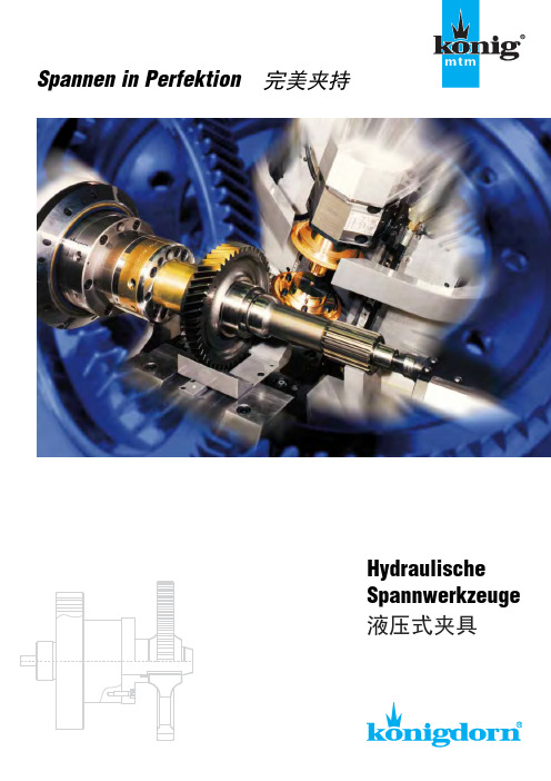
柯尼格 液压式夹具 Koenigdorn
4
Königdorn®的夹持方式
根据加工情况和机床情况,可以有 许多不同的夹持方式,这些柯尼格 夹具都会向您一一展示。
在下述的图例中,我们将向您介绍 4种最常见的可能性。
自动夹持
手动夹持 不借助工具
夹持压力可以通过机械式、启动式、液压式或者电磁式的方式,拉动或压缩夹持活塞来实现。 这种方式主要被用于半自动或者全自动的机床上。
一个内置的消耗显示装置*将提高操 作的安全性,因为在操作过程中, 存在这样的可能性,操作人员可以 在没有其它辅具的条件下判断设备 和夹具的运行状况。
* 更多的说明请见31页
8
液压式夹具 齿轮磨削加工
液压式卡盘夹具 用于轴类零件的夹持 如图所示,在轴类零件的齿轮加工 中,轴的夹持位置常常在轴的轴承 联接端位置。工件会被手动的放置 于夹持位置上。通过一个滑动顶尖 套筒或者尾顶尖把工件送入卡盘。 夹持力由轴向导入的液压力实现。 夹具中内置的压力转换机构可以保 证夹具所需的夹持压力。
柯尼格根据客户的特殊要求,构思 设计和制造所需的夹具产品。
几乎所有相关的特殊单件夹具产品, 都是根据客户的特殊加工任务而为 为其量身定制的。
- 1、下载文档前请自行甄别文档内容的完整性,平台不提供额外的编辑、内容补充、找答案等附加服务。
- 2、"仅部分预览"的文档,不可在线预览部分如存在完整性等问题,可反馈申请退款(可完整预览的文档不适用该条件!)。
- 3、如文档侵犯您的权益,请联系客服反馈,我们会尽快为您处理(人工客服工作时间:9:00-18:30)。
BERG拉刀爪、BERG拉爪、BERG液压夹紧器、BERG卡盘、BERG卡爪、BERG液压机械爪,BERG附件铣头夹紧装置、BERG机床附件
BERG是领先世界的夹持系统工具制造商。
Berg Spanntechnik(BERG夹紧)产品包括电液快速换模系统(压力机行业)、拉刀和夹紧产品、特殊夹紧系统及液压夹紧器、卡盘、卡爪、液压机械爪。
产品广泛用于工件固定、工件夹紧、刀具夹持、滑枕铣头夹紧。
上海智川工贸有限公司有限公司还:IGUS、ROLLON、FRAKO、ERO、SCHAEVITZ、THOMAS、R.STAHL、SUN、HYDRAFORCE、A TOS、KNF、SUCO、ELEKTRIM、SEIKO、PERMA PURE、VOITH、HAWE、ASCON、TECNOLOGIC、STERLING、HOKUYO、ESTERS、YUKEN、、REXROTH、EDUR、VTI、TYCO、DOLD、CPS、CRYDOM、FINDER、PIZZATO、MIDORI、FUJIKURA、Y AMATAKE、KOYO、BROOKCROMPTON、PALL、MOOG、EWO、PEWATRON、W AIRCOM、LECO、EUROTHERM、JUMO、VEGA、DAITO、AMISCO、ENTEK、BUHLER、ASM、ENTEK、WOERNER、SAIET、BIRCHER、BELLOFRAM、MTS、BTI、PARKER、ALTHEN、SEIKO、ERSCE、AEG、GUNTHER。
上海智川工贸有限公司优势供应德国BERG拉刀爪、BERG拉爪、BERG液压夹紧器、BERG 卡盘、BERG卡爪、BERG液压机械爪,BERG附件铣头夹紧装置、BERG机床附件等全系列产品。
