供电毕设(含外文文献+中文翻译)
电气专业毕设英文文献(格式已修改)
本科毕业设计外文文献及译文文献题目:Direct Torque Control of Induction MotorsUtilizing Three-Level Voltage Source Inverters 文献作者: Xavier del Toro Garcia, Antoni Arias, Marcel G.Jayne and Phil A. Witting文献来源: IEEE Trans. Ind. Electron, vol. 51,No. 4,pp.744–757发表日期:2004年8月班级:姓名:学号:指导教师:翻译日期:英文原文:Direct Torque Control of Induction Motors Utilizing Three-Level Voltage Source Inverters Xavier del Toro Garcia, Antoni Arias, Marcel G. Jayne,and Phil A. WittingAbstract—A new control strategy for induction motors based on direct torque control is presented which employs a three-level inverter instead of the standard two-level inverter. The controller is designed to achieve a torque ripple reduction by taking advantage of the increase in the number of inverter states available in a three-level inverter. The harmonic distortion in the stator currents and the switching frequency of the semi-conductor devices are also reduced in the new control system presented.Index Terms—Induction motor drives, three-level converter, torque control.I. INTRODUCTIONThe standard voltage source inverter (VSI) traditionally used in electrical drive systems is the two-level VSI, which unfortunately has a number of inherent limitations. For example, the maximum voltage that can be supported by the semiconductor switching devices in the VSI limits the maximum value of dc-link voltage. Furthermore, the output voltages and currents from the VSI can contain high harmonic distortion.The output voltage waveforms can also contain large values of dV/dt, which contribute to the degradation of the machine windings insulation and bearings, and also produce considerable electromag-netic interference during operation. New multilevel VSI topologies,however, can considerably reduce many of these limitations [1].The most commonly used multilevel topology is the three-level neutral point clamped (NPC) VSI[2]. This type of VSI has advantages over the standard two-level VSI, such as a greater number of levels in the output voltage waveforms, less harmonic distortion, and lower switching frequencies.Direct torque control (DTC) has emerged to become a possible alternative to the well-known vector control strategies for induction motor control systems [3], [4]. Although considerable research has been made into the two-level topologies associated with this method of control, the amount of research carried out to date into DTC systems employing multilevel topologies is still rather limited. The major advantage of the three-level VSI topology when applied to DTC is the increase in the number of voltage vectors available. This means the number of possibilities in the vector selection process is greatly increased and leads to a more accurate control system, which can result in a reduction of the torque and flux ripples. This is of course achieved at the expense of an increase in the complexity of the vector selection process. Although several authors have recently proposed the implementation of DTC utilizing this higher-level topology, their approaches are based on the use of more complex vector selection tables combined with modulation techniques based on analytical methods which have machine parameter dependency[5] [6]. A different approach is a selection table based on the concept of virtual vectors [7]. These new methods considerably increasethe complexity of the control strategy when compared to the classical DTC system[3], and they cannot be extended to different multilevel topologies with a higher number of levels because of the table selection method adopted.Fig. 1. Schematic diagram of the new controller.This paper describes a controller based on DTC that can be applied to different multilevel VSI topologies. It avoids the use of hysteresis comparators and look-up tables, and it does not require the knowledge of the motor model in the control system except for the inherent estimator as in the classical DTC system.II. NEW CONTROLLERThe general structure of the new controller is shown in Fig. 1. This novel controller generates a reference stator voltage vector (u∗s) in α–βcoordinates (usα,usβ) according to the DTC basic principle, rather thanusing the VSI state look-up table as used in classical DTC. This approach adopted is close to the DTC with space vector modulation scheme with closed-loop flux and torque control, and stator flux oriented control [4]. More recently, other similar methods based on the predictive torque control concept have appeared [8] [9].The inputs to the controller are the stator flux error (eψs),the torque error (eΓe) and, additionally, the stator flux angular speed (ωB),which is obtained to incorporate the back electromotive force (BEMF) term to improve the torque response at different operating points. The reference voltage vector calculated by the controller can be synthesized using different techniques with different degrees of complexity, such as choosing the nearest vector available or using modulation techniques [9]–[11]. This controller can be applied to any topology because the type of VSI only affects the way the reference voltage vector has to be synthesized.The controller is based on the principle that the desired decoupled control of the stator flux modulus and torque is achieved by the controller acting on the respective radial and tangential components of the stator flux vector (ψB). The variation of the stator flux vector is approximately proportional to the voltage vector applied to the motor. Therefore, when calculating the reference voltage vector (in x–y coordinates fixed to the stator flux vector), the tangential component (u∗sy) will depend on the torque error (eΓe), whereas the radial component (u∗sx) will depend on the stator flux error (eψB). As can be seen in Fig. 1, two closed-loop proportional controllers are employed to generate the components of the reference voltage vector. Kψs and KΓe are the proportional gains of these controllers and have been tuned experimentally to achieve a minimum torque and flux ripple. Their initial values can be set to approximately theratio between nominal stator voltage and nominal stator flux modulus for Kψs, and the ratio between nominal stator voltage and nominal stator fluxFig. 2. Torque response characteristics for classical DTC with a two-level VSI. Operating point: Γ=7.4 Nm. ωm = 200 r/min.modulus for Kψs, and the ratio between nominal stator voltage and nominal torque for KΓe.It can be seen in Fig. 1 that a feedforward action that compensates the BEMF term is added to the output of the torque controller to calculate the tangential component of the reference voltage vector. The BEMF term is obtained by multiplying the nominal stator flux modulus (ψsn) and the stator flux angular speed (ωs), which is previously filtered by means of a low-pass filter.The reference vector in x–y coordinates is then transformed to α–β fixed coordinates. The novel controller developed synthesizes the reference voltage by choosing the nearest VSI vector to the reference voltage vector. The nearest vector is found by means of calculating the minimum distance of the voltage vectors that can be delivered by the VSIto the reference voltage vector. This calculation involves evaluating the modulus of the difference between vectors. The complexity of the system presented is increased when compared to classical DTC due to the use of proportional controllers instead of hysteresis comparators, the x–y to α–β coordinate transformation and the method to find the nearest vector. Finally, it should be noted that the balance of the neutral point voltage is one of the main issues associated with the control of the three-level NPC VSI [11]. In the novel controller the balance is achieved by selecting the appropriate configuration among the redundant possibilities that exist for some of the vectors delivered by the VSI.III. EXPERIMENTAL RESULTSThe practical implementation of the new controller is based on a dSpace DS1103 board that performs the control tasks. This board contains a PowerPC and a DSP. A three-level NPC VSI utilizing IGBT devices is used to supply a 380/220-V four-pole 1.1-kW cage-rotor induction motor. The dc-link voltage employed is 200 V. Figs. 2 and3 show the steady-state torque responses at 200 r/min and nominal torque conditions (7.4 Nm) for the classical DTC strategy with a two-level VSI and the new control system employing a three-level VSI described in this paper, respectively. The sample time used was 100 µs in both systems.To assess the performance of both systems, the torque standard deviation (σΓe) is calculated for the torque ripple. Additionally, the flux standard deviation (σψs), the total harmonic distortion (THD) of the stator current THD_iS, and the mean switching frequency in the semiconductor devices (FSw) are calculated for both systems. From the experimentalresults shown in Figs. 2 and 3, it is apparent that the torque ripple for the new system utilizing a three-level VSI is considerably reduced. The resultFig. 3. Torque response characteristics for the new controller with a three-level VSI. Operating point: Γ=7.4 Nm. ωm = 200 r/min.of the VSI switches in the proposed system are both reduced by more than 50%. The switching frequency is reduced due to the utilization of a three-level VSI. In this type of VSI, some transitions between the three possible states of a leg do not involve the commutation of all the switches.IV. CONCLUSIONA new controller based on the DTC principle is presented, and it is shown that the controller can be easily implemented in a three-level VSI drive system. The new controller does not involve the use of any motor model parameters, as in classical DTC, and therefore, the control systemis more robust compared to other methods that incorporate motor parameters. The experimental results obtained for the new DTC scheme employing a three-level VSI illustrate a considerable reduction in torque ripple, flux ripple, harmonic distortion in the stato currents,and switching frequency when compared to existing classic DTCsystems utilizing the two-level VSI.REFERENCES[1] J. Rodriguez, J. Lai, and F. Z. Peng, “Multilevel inverters: A survey of topologies, controls, and applications,” IEEE Trans. Ind. Electron.,vol. 49, no. 4, pp. 724–738, Aug. 2002.[2] A. Nabae, I. Takahashi, and H. Akagi, “A new neutral-point-clamped PWM inv erter,” IEEE Trans. Ind. Appl., vol. IA-17, no. 5, pp. 518–523,Sep./Oct. 1981.[3] I. Takahashi and T. Noguchi, “A new quick-response and high-efficiency control strategy of an induction motor,” IEEE Trans. Ind. Appl.,vol. IA-22, no. 5, pp. 820–827, Sep./Oct. 1986.[4] G. Buja and M. P. Kazmierkowski, “Direct torque control of PWM inverter-fed AC motors—A survey,” IEEE Trans. Ind. Electron., vol. 51,no. 4, pp. 744–757, Aug. 2004.[5] K.-B. Lee, J.-H. Song, I. Choy, and J.-Y. Yoo, “Torque ripple reduction in DTC of induction motor driven by three-level inverter with low switching frequency,” IEEE Trans. Power Electron., vol. 17, no. 2, pp. 255–264,Mar. 2002.[6] G. Brando and R. Rizzo, “An optimized algorithm for torque oscillation reduction in DTC-induction motor drives using 3-level NPC inverter,” in Proc. IEEE ISIE, Ajaccio, France, Jun. 2004, pp. 1215–1220.[7] Z. Tan, Y. Li, and M. Li, “A direct torque control of induction motor based on three-level NPC inverter,” in Proc. IEEE PESC, Vancouver, BC, Canada, Jun. 2001, pp. 1435–1439.[8] P. Correa, M. Pacas, and J. Rodríguez, “Predictive torque control for inverter-fed induction machines,” IEEE Trans. Ind. Electron., vol. 54,no. 2, pp. 1073–1079, Apr. 2007.[9] M. Nemec, D. Nedeljkovic, and V. Ambroic, “Predictive torque control of induction machines using immediate flux control,” IEEE Trans. Ind. Electron., vol. 54, no. 4, pp. 2009–2017, Aug. 2007.[10] A. K. Gupta and A. M. Khambadkone, “A space vector PWM scheme for multilevel inverters based on two-l evel space vector PWM,” IEEE Trans. Ind. Electron., vol. 53, no. 5, pp. 1631–1639, Oct. 2006.[11] J. Pou et al., “Fast-processing modulation strategy for the neutral-point-clamped converter with total elimination of low-frequency voltage oscillations in t he neutral point,” IEEE Trans. Ind. Electron., vol. 54, no. 4, pp. 2288–2294, Aug. 2007.中文译文:基于三电平电压型逆变器的异步电机的直接转矩控制摘要:一种基于直接转矩控制的电动机的新型控制方式,其采用了三电平逆变器,而非标准的两个电平逆变器。
供电系统毕业设计

摘要随着科技的不断发展和社会的全面进步,人民生活水平不断提高,电力能源已深入到了人们的日常生活和工作中去,对电力工业的发展极其相关问题的研究层出不穷。
基于目前我国电力工业飞速发展的现状,结合新型工厂发展的实际要求,倡导“安全、高效、节能”的方针,集变电、配电、照明、自动控制与调节、建筑防雷与保护、电脑设备管理于一体的现代化工厂供用电系统。
本设计在充分调查工厂符合设备的情况下,采用需要系数法计算全厂电力负荷,据此与电业部门签订协议,确定供电等级。
按照工厂的实际要求进行系统的无功补偿,确定视在计算负荷,将全厂电力负荷按其工作要求的不同分为不同负荷类别,根据工厂发展和规划要求,选择两台厂用主变压器,互为备用的方式相接,保证供电的可靠性。
绘制系统主接线图,优选厂区电气设备,根据发热和稳定性要求进行校验,最后确定防雷保护和接地措施,保证提高用电可靠性和经济运行。
关键词:供电系统,负荷计算,短路计算,变压器,防雷设计AbstractWith constant development of science and technology and the progressing in an all-round way of the society,the living standards of the people are improving constantly,the electric energy has already got deeply to our daily life and work,the study on extremely relevant problems of development of power industry emerges in an endless stream. It is on the basis of the current situation that the power industry of our country develops at full speed at present to originally design, combine the actual demand for development of new-type factory,advocate the policy of"safe,high-efficient,energy-conservation",collect the switchyard,distribution,illumination,automatically control and regulate,the building defend thunder,protection,computer equipment control and offer the power consuming system in the integrative modern chemical plant.Originally design in case of fully investigating the factory accords with equipment,it needs coefficient law to calculate the whole factory to load electrically to adopt,sign the agreement with electricity industry department in view of the above,confirm the grade of supplying power.Carry on having according to actual demand of factory work compensate,confirm apparent to calculate load systematic, electric load different to divide different load classification into according to job requirements their the whole factory,develop and is it require according to factory,choose two platform factory use the main voltage transformer to plan,both as reserve way and meet,the dependability of guaranteeing to supply power.Draw the main wiring diagram of system,the factory electric equipment of optimum seeking, and the stability demand carry on check-up according to generating heat, confirm finally that defends thunder protection and earth measure, guarantee to improve the dependability and economical operation of power consuming.Keywords:Electric power system,load is calculated,short out and calculate,voltage transformer,defend the thunder to design目录摘要 (I)Abstract (II)1绪言 (1)1.1我国电力工业的发展的过程、现状和未来 (1)1.2工厂供电系统设计的意义 (2)2负荷计算 (3)2.1该工厂负荷情况统计 (3)2.2本系统设计框图 (3)2.3计算方法 (4)2.4绘制最大负荷计算图 (4)2.5负荷计算 (5)2.5.1负荷计算 (5)2.5.2全厂电力负荷的分类 (6)2.5.3绘制负荷等级指示图 (6)2.6确定工厂供电电压等级 (6)2.7无功补偿 (6)2.7.1无功补偿的方式 (6)2.7.2无功补偿容量的计算 (7)3电线、电缆的选择 (9)3.1按载流量选择 (9)3.2按电压损失选择 (9)3.3与线路保护设备相配合选择 (9)3.4热稳定校验 (9)4变压器选择 (11)4.1变压器类型的确定 (11)4.2变压器的过负荷能力 (11)4.2.1正常过负荷能力 (11)4.3变压器数量的确定 (12)4.3.1按负荷等级大小需选择变压器 (12)4.3.2变压器容量的确定 (12)5电气主接线 (15)5.1电气主接线的要求及设计依据 (15)5.2常用的工厂电气接线图的比较 (15)6短路计算 (18)6.1短路的原因 (18)6.2短路对设备及系统的危害 (18)6.3短路电流计算的目的 (18)6.4短路的类型 (18)6.5本系统设计的一般规定和假设 (18)6.6本系统的短路计算 (19)6.6.1短路计算用图 (19)6.6.2三相短路计算 (19)6.6.3单相短路电流计算 (20)6.6.4短路电流的电动力效应 (20)6.6.5短路电流的热效应 (20)7电气设备的选择 (22)7.1正常的工作条件选择 (22)7.1.1按使用环境温度选型 (22)7.1.2按额定电压选择 (22)7.1.3按额定电流选择、 (22)7.2低压电气设备选择 (22)7.2.1低压熔断器的选择计算 (23)7.2.2自动空气断路器的选择 (24)8保护措施与保护装置的选择 (28)8.1变压器保护 (28)8.1.1变压器的瓦斯保护装置 (29)8.1.2变压器的差动保护装置 (29)8.2电动机保护 (30)9接地措施 (31)9.1低压配电系统接地 (31)9.2电气装置接地 (31)9.3防静电接地 (31)9.4接地装置 (32)10防雷措施 (33)10.1总体原则 (33)10.2常用建筑物的防雷措施 (33)10.2.1防直击雷的措施 (33)10.2.2防雷电感应的措施 (34)11总结与展望 (35)致谢 (36)参考文献 (37)附录 (38)1绪言1.1我国电力工业的发展的过程、现状和未来电力工业是生产销售电能为主的为电力客户服务行业,经过发、输、变、配等过程,通过供电设备供给电力用户,电能是经过一次能源转换过来的二次能源,已成为国民经济和人民生活的必须品,各行各业,包括重工业、轻工业、交通运输业、商业和服务性行业以及信息产业无不采用电能作为能源。
电气专业毕业设计外文翻译
附录1:外文资料翻译A1.1外文资料题目26.22 接地故障电路开关我们目前为止报道的接地方法通常是充分的, 但更加进一步的安全措施在某些情况下是必要的。
假设例如, 有人将他的手指伸进灯口(如Fig.26.45示)。
虽然金属封入物安全地接地, 但那人仍将受到痛苦的震动。
或假设1个120V 的电炉掉入游泳池。
发热设备和联络装置将导致电流流入在水池中的危害,即使电路的外壳被安全地接地,现在已经发展为当这样的事件发生时,设备的电源将被切断。
如果接地电流超过5mA ,接地开关将在5 ms 内跳掉,这些装置怎么运行的?如Fig.26.46所示,一台小变流器缠绕上导线 ,第二步是要连接到可能触发开合120 V 线的一台敏感电子探测器。
在正常情况下流过导体的电流W I 与中性点上的电流N I 准切的相等,因此流经核心的净潮流(N W I I -)是零。
结果,在核心没有产生电流,导致的电压F E 为零,并且开关CB 没有动作。
假设如果某人接触了一个终端(图Fig.26.45示),故障电流F I 将直接地从载电线漏到地面,这是可能发生的。
如果绝缘材料在马达和它的地面封入物之间断开,故障电流也会被产生。
在以下任何情况下,流经CT 的孔的净潮流等于F I 或L I ,不再是零。
电流被产生,并且产生了可以控制CB 开关的电压F E 。
由于5 mA 不平衡状态只必须被检测出,变压器的核心一定是非常有渗透性的在低通量密度。
Supermalloy 是最为常用的,因为它有相对渗透性典型地70000在通量密度仅4mT 。
26.23 t I 2是导体迅速发热的因素它有时发生于导体短期内电流远大于正常值的情况下,R I 2损失非常大并且导体的温度可以在数秒内上升几百度。
例如,当发生严重短路时,在保险丝或开关作用之前,会有很大的电流流过导体和电缆。
此外,热量没有时间被消散到周围,因此导体的温度非常迅速地增加。
在这些情况下什么是温度上升? 假设导体有大量m ,电阻R 和热量热容量c 。
电气供配电系统大学毕业论文英文文献翻译及原文

毕业设计(论文)外文文献翻译文献、资料中文题目:供配电系统文献、资料英文题目:POWER SUPPLY AND DISTRIBUTIONSYSTEM文献、资料来源:文献、资料发表(出版)日期:院(部):专业:班级:姓名:学号:指导教师:翻译日期: 2017.02.14POWER SUPPLY AND DISTRIBUTION SYSTEMABSTRACTThe basic function of the electric power system is to transport the electric power towards customers. The l0kV electric distribution net is a key point that connects the power supply with the electricity using on the industry, business and daily-life. For the electric power, allcostumers expect to pay the lowest price for the highest reliability, but don't consider that it's self-contradictory in the co-existence of economy and reliable.To improve the reliability of the power supply network, we must increase the investment cost of the network construction But, if the cost that improve the reliability of the network construction, but the investment on this kind of construction would be worthless if the reducing loss is on the power-off is less than the increasing investment on improving the reliability .Thus we find out a balance point to make the most economic,between the investment and the loss by calculating the investment on power net and the loss brought from power-off.KEYWARDS:power supply and distribution,power distribution reliability,reactive compensation,load distributionTEXTThe revolution of electric power system has brought a new big round construction,which is pushing the greater revolution of electric power technique along with the application of new technique and advanced equipment. Especially, the combination of the information technique and electric power technique, to great ex- tent, has improved reliability on electric quality and electric supply. The technical development decreases the cost on electric construction and drives innovation of electric network. On the basis of national and internatio- nal advanced electric knowledge, the dissertation introduces the research hotspot for present electric power sy- etem as following.Firstly, This dissertation introduces the building condition of distribution automation(DA), and brings forward two typical construction modes on DA construction, integrative mode and fission mode .It emphasize the DA structure under the condition of the fission mode and presents the system configuration, the main station scheme, the feeder scheme, the optimized communication scheme etc., which is for DA research reference.Secondly, as for the (DA) trouble measurement, position, isolation and resume, This dissertation analyzes the changes of pressure and current for line problem, gets math equation by educing phase short circuit and problem position under the condition of single-phase and works out equation and several parameter s U& , s I& and e I& table on problem . It brings out optimized isolation and resume plan, realizes auto isolation and network reconstruction, reduces the power off range and time and improves the reliability of electric power supply through problem self- diagnoses and self-analysis. It also introduces software flow and use for problem judgement and sets a model on network reconstruction and computer flow.Thirdly, electricity system state is estimated to be one of the key techniques in DA realization. The dissertation recommends the resolvent of bad measurement data and structure mistake on the ground of describing state estimate way. It also advances a practical test and judging way on topology mistake in state estimate about bad data test and abnormity in state estimate as well as the problem and effect on bad data from state measure to state estimate .As for real time monitor and control problem, the dissertation introduces a new way to solve them by electricity break and exceptional analysis, and theway has been tested in Weifang DA.Fourthly, about the difficulty for building the model of load forecasting, big parameter scatter limit and something concerned, the dissertation introduces some parameters, eg. weather factor, date type and social environment effect based on analysis of routine load forecasting and means. It presents the way for electricity load forecasting founded on neural network(ANN),which has been tested it’s validity by example and made to be good practical effect.Fifthly, concerning the lack of concordant wave on preve nting concordant wave and non-power compensation and non-continuity on compensation, there is a topology structure of PWM main circuit and nonpower theory on active filter the waves technique and builds flat proof on the ground of Saber Designer and proves to be practical. Meanwhile, it analyzes and designs the way of non-power need of electric network tre- nds and decreasing line loss combined with DA, which have been tested its objective economic benefit throu- gh counting example.Sixthly, not only do the dissertation design a way founded on the magrginal electric price fitted to our present national electric power market with regards to future trends of electric power market in China and fair trade under the government surveillance, that is group competitio n in short-term trade under the way of grouped price and quantity harmony, but also puts forward combination arithmetic, math model of trading plan and safty economical restriction. It can solve the original contradiction between medium and long term contract price and short term competitive price with improvement on competitive percentage and cut down the unfair income difference of electric factory, at the same time, it can optimize the electric limit for all electric factories and reduce the total purchase charge of electric power from burthen curve of whole electric market network.The distribution network is an important link among the power system. Its neutral grounding mode and operation connects security and stability of the power system directly. At the same time, the problem about neutral grounding is associated with national conditions, natural environment, device fabrication and operation. For example, the activity situation of the thunder and lightning, insulating structure and the peripheral interference will influence the choice of neutral grounding mode Conversely, neutral grounding mode affects design, operation, debugs and developing. Generally in the system higher in grade in the voltage, the insulating expenses account for more sizable proportion at the total price of the equipment. It is very remarkable to bring the economic benefits by reducing the insulating level. Usually such system adopt the neutral directly grounding andadopt the autoreclosing to guarantee power supply reliability. On the contrary, the system which is lower in the voltage adopts neutral none grounding to raise power supply reliability. So it is an important subject to make use of new- type earth device to apply to the distribution network under considering the situation in such factors of various fields as power supply reliability, safety factor, over-voltage factor, the choice of relay protection, investment cost, etc.The main work of this paper is to research and choice the neutral grounding mode of the l0kV distribution network. The neutral grounding mode of the l0kV network mainly adopts none grounding, grounding by arc suppressing coil, grounding by reactance grounding and directly grounding. The best grounding mode is confirmed through the technology comparison. It can help the network run in safety and limit the earth electric arc by using auto-tracking compensate device and using the line protection with the detection of the sensitive small ground current. The paper introduces and analyzes the characteristic of all kind of grounding modes about l0kV network at first. With the comparison with technological and economy, the conclusion is drawn that the improved arc suppressing coil grounding mode shows a very big development potential.Then, this paper researches and introduces some operation characteristics of the arc suppressing coil grounding mode of the l0kV distribution network. And then the paper put emphasis on how to extinguish the earth electric arc effectively by utilizing the resonance principle. This paper combines the development of domestic and international technology and innovative achievement, and introduces the computer earth protection and autotracking compensate device. It proves that the improved arc suppressing coil grounding mode have better operation characteristics in power supply reliability, personal security, security of equipment and interference of communication. The application of the arc suppressing coil grounding mode is also researched in this paper.Finally, the paper summarizes this topic research. As a result of the domination of the arc suppressing coil grounding mode, it should be more popularized and applied in the distribution network in the future.The way of thinking, project and conclusions in this thesis have effect on the research to choose the neutral grounding mode not only in I0kV distribution network but also in other power system..The basic function of the electric power system is to transport the electric power towards customers. The l0kV electric distribution net is a key point that connects the power supply with the electricity using on the industry, business and daily-life. For the electric power, all costumers expect to pay the lowest price for the highest reliability, butdon't consider that it's self-contradictory in the co-existence of economy and reliable. To improve the reliability of the power supply network, we must increase the investment cost of the network con- struction But, if the cost that improve the reliability of the network construction, but the investment on this kind of construction would be worthless if the reducing loss is on the power-off is less than the increasing investment on improving the reliability .Thus we find out a balance point to make the most economic, between the investment and the loss by calculating the investment on power net and the loss brought from power-off. The thesis analyses on the economic and the reliable of the various line modes, according to the characteristics various line modes existed in the electric distribution net in foshan..First, the thesis introduces as the different line modes in the l0kV electric distribution net and in some foreign countries. Making it clear tow to conduct analyzing on the line mode of the electric distribution net, and telling us how important and necessary that analyses are.Second, it turns to the necessity of calculating the number of optimization subsection, elaborating how it influences on the economy and reliability. Then by building up the calculation mode of the number of optimization subsection it introduces different power supply projects on the different line modes in brief. Third, it carries on the calculation and analyses towards the reliability and economy of the different line modes of electric distribution net, describing drafts according by the calculation. Then it makes analysis and discussion on the number of optimization subsection.At last, the article make conclusion on the economy and reliability of different line modes, as well as, its application situation. Accordion to the actual circumstance, the thesis puts forward the beneficial suggestion on the programming and construction of the l0kV electric distribution net in all areas in foshan. Providing the basic theories and beneficial guideline for the programming design of the lOkV electric distribution net and building up a solid net, reasonable layout, qualified safe and efficiently-worked electric distribution net.。
电力系统毕业论文中英文外文文献翻译精选全文完整版

可编辑修改精选全文完整版电力系统电力系统介绍随着电力工业的增加,与用于生成和处置现今大规模电能消费的电力生产、传输、分派系统相关的经济、工程问题也随之增多。
这些系统组成了一个完整的电力系统。
应该着重提到的是生成电能的工业,它不同凡响的地方在于其产品应按顾客要求即需即用。
生成电的能源以煤、石油,或水库和湖泊中水的形式贮存起来,以备以后所有需。
但这并非会降低用户对发电机容量的需求。
显然,对电力系统而言服务的持续性相当重要。
没有哪一种服务能完全幸免可能显现的失误,而系统的本钱明显依托于其稳固性。
因此,必需在稳固性与本钱之间找到平稳点,而最终的选择应是负载大小、特点、可能显现中断的缘故、用户要求等的综合表现。
但是,网络靠得住性的增加是通过应用必然数量的生成单元和在发电站港湾各分区间和在国内、国际电网传输线路中利用自动断路器得以实现的。
事实上大型系统包括众多的发电站和由高容量传输线路连接的负载。
如此,在不中断整体服务的前提下能够停止单个发电单元或一套输电线路的运作。
现此生成和传输电力最普遍的系统是三相系统。
相关于其他交流系统而言,它具有简便、节能的优势。
尤其是在特定导体间电压、传输功率、传输距离和线耗的情形下,三相系统所需铜或铝仅为单相系统的75%。
三相系统另一个重要优势是三相电机比单相电机效率更高。
大规模电力生产的能源有:1.从常规燃料(煤、石油或天然气)、城市废料燃烧或核燃料应用中取得的蒸汽;2.水;3.石油中的柴油动力。
其他可能的能源有太阳能、风能、潮汐能等,但没有一种超越了试点发电站时期。
在大型蒸汽发电站中,蒸汽中的热能通过涡轮轮转换为功。
涡轮必需包括安装在轴承上并封锁于汽缸中的轴或转子。
转子由汽缸周围喷嘴喷射出的蒸汽流带动而平稳地转动。
蒸汽流撞击轴上的叶片。
中央电站采纳冷凝涡轮,即蒸汽在离开涡轮后会通过一冷凝器。
冷凝器通过其导管中大量冷水的循环来达到冷凝的成效,从而提高蒸汽的膨胀率、后继效率及涡轮的输出功率。
毕业设计外文原文+翻译(电力系统)
河南理工大学HENAN POLYTECHNIC UNIVERSITY英文文献翻译En glish literature tran slati on学院:电气工程与自动化学院专业班级:___________ 电气11-4班_______ 姓名: __________________ 宋家鹏_______ 学号:311008001120 __________ 扌旨导老师:____________ 汪旭东_______2014年6月5日河南理工大学HENAN POLYTECHNIC UNIVERSITY2.5 对称三相电路在这一部分,我们介绍三相对称电路的一下几个话题:丫连接,相电压,线电压,线电流,△形连接负荷,△ - Y变换,以及等效的相图。
c Ca Ab B图2-10三相Y连接电源带Y连接对称负荷电路图对称Y连接图2-10显示的是一个三相Y连接电源带Y连接对称负荷电路图。
对于Y连接电路,每个相的中性点是连接起来的。
在图2-10中电源中性点标记的是n,而负载中性点标记的是N。
把三相电源假设为理想电源,即阻抗忽略不计。
同时,电源和负载之间线路阻抗,中性点n与N之间的线路阻抗也可忽略不计。
三相负荷是对称的,意味着三相之中任意两相间的阻抗是相同的。
对称相电压在图2-10中,三相电源的终端呗标记为a、b、c,电源相电压标记为E an ,E bn,E cn,当电源的三相电压有相同的幅度,任意两相之间互差120度角时,电源是对称的。
当以E an 作为参考相量时,相电压的幅值是10V,对称三相相电压如下所示:E an=10 0E bn10 120 10 240 (2.5.1 )E cn10 120 10 240河南理工大学HENAN POLYTECHNIC UNIVERSITY图2-11以E an 作为参考的对称正序相电压向量图当E an 超前E bn 120度,E bn 超前E cn 以120度角时,此时的相序称为正相序或 者abc 相序。
工厂供电课程设计 毕业设计
摘要工厂供电(plant power supply)就是指工厂所需电能的供应和分配,亦称工厂配电。
在工厂里,电能虽然是工业生产的主要能源和动力,但它在产品成本中所占的比重一般很小。
因此电能在工业生产中的重要性,并不在于它在产品成本中或投资总额中所占的比重多少,而在于工业生产实现电气化以后,可以大大增加产量,提高产品质量,提高劳动生产率,降低生产成本,减轻工人的劳动强度,改善工人的劳动条件,有利于实现生产过程自动化。
本次设计根据课题提供的某机械制造厂的用电负荷和供电条件,并适当考虑生产的发展,按照国家相关标准、设计准则,本着安全可靠、技术先进、经济合理的要求确定本厂变电所的位置和形式。
通过负荷计算,确定主变压器的台数和容量。
进行短路电流计算,选择变电所主接线方案及高低压设备与进出线,合理选择整定继电器保护装置,最后按要求写出设计说明书,并绘出设计图样。
具体过程和步骤:根据工厂总平面图,工厂负荷情况,供电电源情况,气象资料,地区水文资料和电费制度等,先计算电力负荷,判断是否要进行无功功率补偿,接着进行变电所位置和型式选择,并确定变电所变压器台数和容量, 主接线方案选择,最后进行短路电流的计算,并对变电所一次设备选择和校验和高低压线路的选择。
第一章设计题目设计一某车间负荷分布:第二章.负荷计算和无功功率计算及补偿一.负荷计算 :负荷计算的方法有需要系数法、二项式等几种,本设计采用需要系数法确定。
主要计算公式有: 有功功率:e d P K P ∙=30 无功功率:ϕtan 3030∙=P Q视在功率:ϕcos 3030P S =计算电流:NU S I 33030= 总的有功计算负荷为 : ∑∑=ipPK P .3030总的无功计算负荷为: ∑∑=i q Q K Q .3030总的视在计算负荷为: 23023030Q P S +=总的计算电流为 : NUS I 33030=()ϕϕarccos tan tan = 1.铸钢车间(1)动力: 6.0cos ,5.0,1800===ϕd e K KW P ()ϕϕarccos tan tan ==1.33 KW KW P 9005.0180030=⨯= var 119733.190030K KW Q =⨯=var6.149711979002230K S =+= KAI 227538036.149730=∙=(2)照明:0tan ,0.1cos ,8.0,30====ϕϕd K KW Pe KW KW P 24308.030=⨯= 030=Q var240242230K S =+= KAI 1092202430==2.热处理车间(1)动力: 8.0cos ,5.0,2100===ϕd e K KW P ()ϕϕarccos tan tan ==0.75KWKW P 105021005.030=⨯= var 5.78775.0105030K KW Q =⨯=var5.13125.78710502230K S =+= KAI 199438035.131230=∙=(2)照明:0tan ,0.1cos ,8.0,30====ϕϕd K KW PeKW KW P 24308.030=⨯= 030=Q var240242230K S =+= KAI 1092202430==3.锻工车间:(1)动力:6.0cos ,25.0,1600===ϕd e K KW P ()ϕϕarccos tan tan ==1.33KWKW P 400160025.030=⨯=var 53233.140030K KW Q =⨯=var6.6655324002230K S =+=KAI 101138036.66530=∙=(2)照明:0tan ,0.1cos ,8.0,30====ϕϕd K KW Pe KW KW P 24308.030=⨯= 030=Q var240242230K S =+= KAI 1092202430==4.焊接车间:(1)动力: 7.0cos ,5.0,200===ϕd e K KW P ()ϕϕarccos tan tan ==1.02KW KW P 1002005.030=⨯= var 10202.110030K KW Q =⨯=var8.1421021002230K S =+=KAI 21738038.14230=∙=(2)照明:0tan ,0.1cos ,8.0,30====ϕϕd K KW Pe KW KW P 24308.030=⨯= 030=Q var240242230K S =+= KAI 1092202430==5.金工车间:(1)动力:33.1tan ,75.0cos ,25.0,400====ϕϕd e K KW PKW KW P 10040025.030=⨯= var 13333.110030K KW Q =⨯=var4.1661331002230K S =+=KAI 25338034.16630=∙=(2)照明:0tan ,0.1cos ,8.0,40====ϕϕd K KW PeKWKW P 32408.030=⨯= 030=Qvar320322230K S =+= KAI 5.1452203230==6.总装车间:(1)动力:73.1tan ,5.0cos ,15.0,200====ϕϕd e K KW PKW KW P 3020015.030=⨯= var 9.5173.13030K KW Q =⨯= var 95.599.51302230K S =+= KAI 91380395.5930=∙=(2)照明:0tan ,0.1cos ,8.0,40====ϕϕd K KW PeKWKW P 32408.030=⨯= 030=Q var320322230K S =+= KAI 5.1452203230==7.空压站:(1)动力:75.0tan ,8.0cos ,8.0,800====ϕϕd e K KW PKW KW P 6408008.030=⨯= var 48075.064030K KW Q =⨯=var8004806402230K S =+=KAI 1216380380030=∙=(2)照明:0tan ,0.1cos ,8.0,30====ϕϕd K KW Pe KW KW P 24308.030=⨯= 030=Q var240242230K S =+= KAI 1092202430==8.煤气站:(1)动力:75.0tan ,8.0cos ,5.0,500====ϕϕd e K KW PKW KW P 2505005.030=⨯= var 5.18775.025030K KW Q =⨯=(2)照明:0tan ,0.1cos ,8.0,40====ϕϕd K KW PeKW KW P 32408.030=⨯= 030=Qvar320322230K S =+=KAI 5.1452203230==车间总的计算负荷:注:( 9.0=∑pK,95.0=∑qK)AKVA KV I A KV A KV S K K Q KW KW P 710738034.46774.46774.32974.3317var 4.3297var )5.1875.7871197(95.04.3317)322502424105024900(9.03022303030=⨯∙=∙=∙+==++⨯==+++++++⨯=2.2无功功率补偿:COS ф = 30P /30S = 3686/5173.4=0.71该厂380V 侧最大负荷时的功率因数只有0.71。
电气专业毕业设计英文文献
电气专业毕业设计英文文献电气专业毕业设计英文文献外文资料与中文翻译外文资料:Relay protection present situation anddevelopment一、Relay protection development present situationElectrical power system's swift development to the relay protection proposed unceasingly the new request, the electronic technology, the computer technology and communication's swift development unceasingly has infused the new vigor for the relay protection technology's development, therefore, the relay protection technology is advantageous, has completed the development 4 historical stage in 40 remaining years of time.After the founding of the nation, our country relay protection discipline, the relay protection design, the relay factory industry and the relay protection technical team grows out of nothing, has passed through the path which in about 10 year the advanced countries half century pass through. In the 50s, our country engineers and technicians creatively absorption, the digestion, have grasped the overseas advanced relay protection equipment performance and the movement technology [1], completed one to have the deep relay protection theory attainments and the rich service experience's relay protection technical team, and grew the instruction function to the national relay protection technical team's establishment. The Achengrelay factory introduction has digested at that time the overseas advanced relay technique of manufacture, has established our country own relay manufacturing industry.Therefore our country has completed the relay protection research, the design, the manufacture, the movement and the teaching complete system in the 60s. This is the mechanical and electrical -like relay protection prosperous time, was our country relay protection technology development has laid the solid foundation.From the late 50s, the transistor relay protection was starting to study. In the 60s to the 80s in is the time which the transistor relay protection vigorous development and widely uses. And the Tianjin University and the Nanjing Electric power Automation Plant cooperation research's 500kv transistor direction high frequency protection develops with the Nanjing Electric power Automation Research institute the transistor high frequency block system is away from the protection, moves on the Gezhou Dam 500 kv lines [2], finished the 500kv line protection to depend upon completely from the overseas import time.From the 70s, started based on the integration operational amplifier's integrated circuit protection to study. Has formed the complete series to the late 80s integrated circuit protection, substitutes for the transistor protection gradually. The development which, the production, the application protected to the early 90s integrated circuit were still in the dominant position, this was theintegrated circuit protection time. The integrated circuit power frequency change quantity direction which develops in this aspect Nanjing Electric power Automation Research institute high frequency protected the influential role [3], the Tianjin University and the Nanjing Electric power Automation Plant cooperation development's integrated circuit phase voltage compensation type direction high frequency protection alsomoved in many 220kv and on the 500kv line.Our country namely started the computer relay protection research from the late 70s [4], the institutions of higher learning and the scientific research courtyard institute forerunner's function. Huazhong University of Science and Technology, the Southeast University, the North China electric power institute, Xi'an Jiaotong University, the Tianjin University, Shanghai Jiaotong University, the Chongqing University and the Nanjing Electric power Automation Research institute one after another has developed the different principle, the different pattern microcomputer protective device. in 1984 the original North China electric power institute developed the transmission line microcomputer protective device first through the appraisal, and obtained the application in the system [5], has opened in our country relay protection history the new page, protected the promotion for the microcomputer to pave the way. In the main equipment protection aspect, the generator which the Southeast University and Huazhong University of Science and Technology develops loses magnetism protection, the generator protection and the generator? Bank of transformers protectionalso one after another in 1989, in 1994 through appraisal, investment movement. The Nanjing Electric power Automation Research institute develops microcomputer line protective device alsoin 1991 through appraisal. Tianjin University and Nanjing Electric power Automation Plant cooperation development microcomputer phase voltage compensation type direction high frequency protection, Xi'an Jiaotong University and Xuchang relay factory cooperation development positive sequence breakdown component direction high frequencyprotection also one after another in 1993, in 1996 through appraisal. Hence, the different principle, the different type's microcomputer line and the main equipment protect unique, provided one group of new generation performance for the electrical power system to be fine, the function was complete, operation reliable relay protection installment. Along with the microcomputer protective device's research, in microcomputer aspects and so on protection software, algorithm has also made many theory progresses. May say that started our country relay protection technology from the 90s to enter the time which the microcomputer protected.二、future development of Relay protectionThe future trend of relay protection technology is to computerization, networking is intelligent, protect, control, measure and data communication developing by integration. The principles of protection of electric power circuits are quite independent of the relay designs which may be applied. For example, if the current to an electriccircuit or a machine is greater than that which can be tolerated, it is necessary to take remedial action. The device for recognizing the condition and initiating corrective measures would be termed as an over-current relay regardless of the mechanists by whichthe function would be accomplished. Because the functions of electromechanical devices are easily described, their performance wills ever as a basis for presenting a description of relays and relay systemsin general.Relays must have the following characteristics: Reliability---The nature of the problem is that the relay may be idle for periods extending into years and then be required tooperatewith fast responds, as intended, the first time. The penalty for failure to operate properly may run into millions of dollars.Selectivity---The relay must not respond to abnormal, but harmless, system conditions such as switching transients or sudden changes in load.Sensitivity---The relay must not fail to operate, even in borderline situations, when operation was planned.Speed---The relay should make the decision to act as close to instantaneously as possible. If intentional time delay is available, it should be predictable and precisely adjustable.Instantaneous---The term means no intentional time delay.There are several possible ways to classify relays: by function, by construction, by application. Relays are one of two basic types of construction: electromagnetic or solid-state. The electromagnetic type relies on the development of electromagnetic forces on movable members,which provide switching action by physically opening or closing sets of contacts. The solid state variety provides switching action with no physical motion by changing the state of serially connected solid state component from no conducting to conducting(or vice versa). Electromagnetic relays are older and more widely used; solid state relays are more versatile, potentially more reliable, and fast.1)ComputerizationWith swift and violent development of computer hardware, computer protect hardware develop constantly even. The power system is improving to the demand that the computer protects constantly, besides basic function protected, should with trouble information of the large capacity and data the long-term parkingspace also, fast data processing function, strong communication capacity, network in order to share the whole system data , information , ability , network of resource with other protection , control device , dispatcher, high-level language programming ,etc.. This requires computer protector to have function which is equivalent to a pc machine. In computer is it develop initial stage to protect, is it make with one minicom relay protection install to imagine. Because the small-scale organism was accumulated greatly, with high costs at that time, dependability was bad, this imagined it was unrealistic . Now, exceed the minicomputer of those years greatly with computer protector size similar worker function , speed , memory capacity of accusing of machine, so make with complete sets of worker person who accuse of opportunity of relay protection already ripe, this will be one of the developing direction that a computer is protected . Tianjin university is it spend whom transformation act as continue the electric protector with computer protector structure self-same one worker person whoaccuse of to develop into already. The advantage of this kind of device is as follows, (1)it have functions of 486pc,it can meet to at present and it is various kinds of function demand where computerprotect future. (2)The size and structure are similar to present computer protector , the craft is superior, takes precautions against earthquakes , defends overheatedly and defending the electromagnetic ability of interfering strongly, can operate it in very abominable working environment , the cost is acceptable.(3)Adopting std bus or pc bus, hardware module , can select different module for use to different protection wantonly , it is flexible , easy to expand to dispose.It is an irreversible development trend to continue the computer , computerization of the electric protector. But to how better meet power system demand, how about raise the dependability of relay protection further, how make heavy economic benefits and social benefit, need carry on concrete deep research.2) NetworkedComputer network become the technological pillar of information age as message and data communication tool, made the mankind producing , basic change has taken place in the appearance with social life. It isinfluencing each industrial field deeply, has offered the powerful communication means for each industrial field too. Up till now, except that protect differentially and unite protecting vertically, all continue electric protector can only react that protect the electric quantity of installing office. The function of relay protection is only limited to excising the trouble component too , narrow the accident coverage. This mainly lack the powerful data communication means. Having already put forward the concept protected systematically abroad, this meant the safe automatics mainly at that time. Because the function of relay protection is not only limited to excising the trouble component and restriction accident coverage (this is primary task), the peace and steadiness that will be guaranteed the whole system run . This require each protect unit can share the whole operation and data , trouble of information of system, each protect unit and coincident floodgate device coordination on the basis of analysing the information and data, guarantee systematic peace and steadiness run . Obviously , realize the primary condition that system protect the whole system every protector of capitalequipment link with the computer network, namely the one that realized the computer protector is networked. This is totally possible under present technological condition .To general protecting systematically , realize the computer networking of the protector has a very great advantage too. It continue electric trouble not the less many in information not systematic can receiving protector ,for trouble nature , judgement and the trouble,trouble of position from measuring the less accurate. Protect to self-adaptation research of principle pass long time very already , make certain achievement too, but should really realize protecting the self-adaptation to the operation way of the system and trouble state, must obtain more system operating and trouble information , the computer that only realizes protecting is networked, could accomplish this . As to the thing that some protectors realize computer networking , can improve the dependability protected . Tianjin Sanxia vltrahigh voltage many return circuit bus bar , 500kv of power station , put forward one distributed principle that bus bar protected to future 1993 such as university, succeed in developing this kind of device tentatively. Principle its bus bar is it disperse several (with protect into bus bar back to way the same ) bus bar protect Entrance to protect traditional concentration type, disperse and install it in every return circuit is protected and rejected , each protect the unit to link with the computer network, each one protects the electric current amount that the unit only inputs a return circuit , after changing it into figure amount, convey to the protection units of other return circuits through the computer network, each protect the unit according to the electric current amount of this return circuit and electric current amount of other return circuits gotfrom computer network, carry on bus bar differential calculation that protect, if result of calculation prove bus bar trouble jump format return circuit circuit breaker only, isolate the bus bar of the trouble. At the time of the trouble outside the bus bar district , each protect the unit and calculate for movements of the external trouble. This kind protect principle by distributed bus barthat network realize with computer, bus bar protect principle have higher dependability than traditional concentration type. Because if one protect unit interfere or mistake in computation and when working up by mistake, can only jump format return circuit , can is it make bus bar to be whole of malignant accident that excise to cause wrong, this is very important to systematic pivot with supervoltage bus bar of hydropower station like SanxiaCan know computer protector networked to can raise and protect the performance and dependability greatly while being above-mentioned, this is an inexorable trend that a computer protects development 3) Protect , control , measure , data communication integratesOn terms that realize computerization of relay protection and networked, the protector is a high performance , multi-functional computer in fact, it is a intelligent terminal on the computer network of whole power system. It can obtain any information and data of operating and trouble of the power system from network , can convey network control centre or any terminal function , and can also finish the measurement , control , data communication function in there is no normal running of trouble cases, namely realize protecting ,controlling , measuring , data communication integrates.At present, for measurement, need that protects and controlling, all equipment of the outdoor transformer substation, two voltage, electric current of voltage transformer, circuit,etc. must with control cable guide to the top management room for instance. Lay control cable take a large amount of investment, make the very much complicated returncircuit 2 times in a large amount. But if above-mentioned protection, control, measure, data communication integrated computer device, install in to is it by the equipment , protect into voltage , electric current amount of equipment in device this after changing into the figure amount to protect outdoor transformer substation on the spot, send to the top management room through the computer network, can avoid a large number of controlcables . If use optic fibre as the transmission medium of the network , can avoid and interfere electromagnetically. The photocurrent mutual inductor of now (ota ) and photovoltage mutual inductor (otv ) have been already during the course of studying and testing, must get application in the power system in the future. In case of adopting ota and otv, namely should be putting and is being protected near the equipment.After the optical signals of ota and otv are input in the integrated device here and changes into an electric signal, what is on one hand uses as being protected calculation is judged ; As measurement amount on the other hand, send to the top management room through the network. Can to protect operation of equipment control order send this integrated device to through network from top management room, therefore the integrated device carries out the operation of the circuit breaker. The university of Tianjin put forward protecting,controlled , measured , communication integration in 1992, develop based on tms320c25 digital signal processor (dsp ) first protecting , control , measure , the integrated device of data communication.4)IntelligentIn recent years, if artificial intelligence technology neural network, hereditary algorithm, evolve plan , fuzzy logic ,etc. get application in power system all field, the research that is used in the field of relay protection has already begun too. Neural network one non-linear method that shine upon, a lot of difficult to list equation or difficult in order to the complicated non-linear question that is solved, use the method of the neural network to be very easily solved .For example the short circuit of crossing the resistance of courseof emergence is a non-linear problem in transmit electricity in the systematic electric potential angle of both sides of line and lay cases, it is very difficult to make discrimination , trouble of position while being correct for distance to protect, is it work up or is it work up to refuse by mistake to lead to the fact; If use neural network method, through a large number of trouble training of sample, so long as sample centralized to fully consider various kinds of situations, can differentiate correctly while any trouble takes place. Other if hereditary algorithm , is it is it have is it solve complicated abilityof problem to asking unique their too to plan to evolve. Artificial intelligence the being method proper to is it can make it solve speed to be fast not to ask to combine. Can predict , the artificial intelligence technology must get application in the field of relay protection, in order to solve the problem difficult to solvewith the routine method.中文翻译:继电保护的现状与发展一、继电保护发展现状电力系统的飞速发展对继电保护不断提出新的要求,电子技术、计算机技术与通信技术的飞速发展又为继电保护技术的发展不断地注入了新的活力,因此,继电保护技术得天独厚,在40余年的时间里完成了发展的4个历史阶段。
供电毕设(含外文文献+中文翻译)
某钢铁企业变电所保护系统及防护系统设计1 绪论1.1 变电站继电保护的发展变电站是电力系统的重要组成部分,它直接影响整个电力系统的安全与经济运行,失恋系发电厂和用户的中间环节,起着变换和分配电能的作用,电气主接线是发电厂变电所的主要环节,电气主接线的拟定直接关系着全厂电气设备的选择、配电装置的布置、继电保护和自动装置的确定,是变电站电气部分投资大小的决定性因素。
继电保护的发展现状,电力系统的飞速发展对继电保护不断提出新的要求,电子技术、计算机技术与通信技术的飞速发展又为继电保护技术的发展不断地注入了新的活力,因此,继电保护技术得天独厚,在40余年的时间里完成了发展的4个历史阶段。
随着电力系统的高速发展和计算机技术、通信技术的进步,继电保护技术面临着进一步发展的趋势。
国内外继电保护技术发展的趋势为:计算机化,网络化,保护、控制、测量、数据通信一体化和人工智能化。
继电保护的未来发展,继电保护技术未来趋势是向计算机化,网络化,智能化,保护、控制、测量、数据通信一体化发展。
微机保护技术的发展趋势:①高速数据处理芯片的应用②微机保护的网络化③保护、控制、测量、信号、数据通信一体化④继电保护的智能化1.2本文的主要工作在本次毕业设计中,我主要做了关于某钢铁企业变电所保护系统及防护系统设计,充分利用自己所学的知识,严格按照任务书的要求,围绕所要设计的主接线图的可靠性,灵活性进行研究,包括:负荷计算、主接线的选择、短路电流计算,主变压器继电保护的配置以及线路继电保护的计算与校验的研究等等。
1.3 设计概述1.3.1 设计依据1)继电保护设计任务书。
2)国标GB50062-92《电力装置的继电保护和自动装置设计规范》3)《工业企业供电》1.3.2 设计原始资料本企业共有12个车间,承担各附属厂的设备、变压器修理和制造任务。
1、各车间用电设备情况用电设备明细见表1.1所示。
2、负荷性质本厂大部分车间为一班制,少数车间为两班或者三班制,年最大有功负荷利用小时数为h2300。
(完整版)电力系统外文英语文献资料

(完整版)电力系统外文英语文献资料Electric Power SystemElectrical power system refers to remove power and electric parts of the part,It includes substation, power station and distribution. The role of the power grid is connected power plants and users and with the minimum transmission and distribution network disturbance through transport power, with the highest efficiency and possibility will voltage and frequency of the power transmission to the user fixed .Grid can be divided into several levels based on the operating voltage transmission system, substructure, transmission system and distribution system, the highest level of voltage transmission system is ZhuWangJia or considered the high power grids. From the two aspects of function and operation, power can be roughly divided into two parts, the transmission system and substation. The farthest from the maximum output power and the power of the highest voltage grade usually through line to load. Secondary transmission usually refers to the transmission and distribution system is that part of the middle. If a plant is located in or near the load, it might have no power. It will be direct access to secondary transmission and distribution system. Secondary transmission system voltage grade transmission and distribution system between voltage level. Some systems only single second transmission voltage, but usually more than one. Distribution system is part of the power system and its retail service to users, commercial users and residents of some small industrial users. It is to maintain and in the correct voltage power to users responsible. In most of the system, Distribution system accounts for 35% of the total investment system President to 45%, andtotal loss of system of the half .More than 220kv voltage are usually referred to as Ultra high pressure, over 800kv called high pressure, ultra high voltage and high pressure have important advantages, For example, each route high capacity, reduce the power needed for the number of transmission. In as high voltage to transmission in order to save a conductor material seem desirable, however, must be aware that high voltage transmission can lead to transformer, switch equipment and other instruments of spending increases, so, for the voltage transmission to have certain restriction, allows it to specific circumstances in economic use. Although at present, power transmission most is through the exchange of HVDC transmission, and the growing interest in, mercury arc rectifier and brake flow pipe into the ac power generation and distribution that change for the high voltage dc transmission possible.Compared with the high-voltage dc high-voltage ac transmission has the following some advantages: (1) the communication with high energy; (2) substation of simple maintenance and communication cost is low; (3) ac voltage can easily and effectively raise or lower, it makes the power transmission and high pressure With safety voltage distribution HVDC transmission and high-voltage ac transmission has the following advantages: (1) it only need two phase conductors and ac transmission to three-phase conductors; (2) in the dc transmission impedance, no RongKang, phase shift and impact overvoltage; (3) due to the same load impedance, no dc voltage, and transfer of the transmission line voltage drop less communication lines, and for this reason dc transmission line voltage regulator has better properties; (4) in dc system withoutskin effect. Therefore, the entire section of route conductors are using; (5) for the same work, dc voltage potential stress than insulation. Therefore dc Wire need less insulation; (6) dc transmission line loss, corona to little interference lines of communication; (7) HVDC transmission without loss of dielectric, especially in cable transmission; (8) in dc system without stability and synchronization of trouble.A transmission and the second transmission lines terminated in substation or distribution substations, the substation and distribution substations, the equipment including power and instrument transformer and lightning arrester, with circuit breaker, isolating switch, capacitor set, bus and a substation control equipment, with relays for the control room of the equipment. Some of the equipment may include more transformer substations and some less, depending on their role in the operation. Some of the substation is manual and other is automatic. Power distribution system through the distribution substations. Some of them by many large capacity transformer feeders, large area to other minor power transformer capacity, only a near load control, sometimes only a doubly-fed wire feeders (single single variable substation)Now for economic concerns, three-phase three-wire type communication network is widely used, however, the power distribution, four lines using three-phase ac networks.Coal-fired power means of main power generating drive generators, if coal energy is used to produce is pushing the impeller, then generate steam force is called the fire. Use coal produces steam to promote the rotating impeller machine plant called coal-fired power plants. In the combustion process, the energy stored in the coal to heat released,then the energy can be transformed into the form within vapor. Steam into the impeller machine work transformed into electrical energy.Coal-fired power plants could fuel coal, oil and natural gas is. In coal-fired power plant, coal and coal into small pieces first through the break fast, and then put out. The coal conveyer from coal unloader point to crush, then break from coal, coal room to pile and thence to power. In most installations, according to the needs of coal is, Smash the coal storage place, no coal is through the adjustable coal to supply coal, the broken pieces of coal is according to the load changes to control needs. Through the broken into the chamber, the coal dust was in the second wind need enough air to ensure coal burning.In function, impeller machine is used to high temperature and high pressure steam energy into kinetic energy through the rotation, spin and convert electricity generator. Steam through and through a series of impeller machine parts, each of which consists of a set of stable blade, called the pipe mouth parts, even in the rotor blades of mobile Li called. In the mouth parts (channel by tube nozzle, the steam is accelerating formation) to high speed, and the fight in Li kinetic energy is transformed into the shaft. In fact, most of the steam generator is used for air is, there is spread into depression, steam turbine of low-pressure steam from the coagulation turbine, steam into the condenses into water, and finally the condensate water is to implement and circulation.In order to continuous cycle, these must be uninterrupted supply: (1) fuel; (2) the air (oxygen) to the fuel gas burning in the configuration is a must; (3) and condenser, condensed from the condensed water supply, sea and river to lake. Common coolingtower; (4) since water vapour in some places in circulation, will damage process of plenty Clean the supply.The steam power plant auxiliary system is running. For a thermal power plant, the main auxiliary system including water system, burning gas and exhaust systems, condensation system and fuel system. The main auxiliary system running in the water pump, condensation and booster pump, coal-fired power plants in the mill equipment. Other power plant auxiliary equipment including air compressors, water and cooling water system, lighting and heating systems, coal processing system. Auxiliary equipment operation is driven by motor, use some big output by mechanical drive pump and some of the impeller blades, machine drive out from the main use of water vaporimpeller machine. In coal-fired power plant auxiliary equipment, water supply pump and induced draft fan is the biggest need horsepower.Most of the auxiliary power generating unit volume increased significantly in recent years, the reason is required to reduce environment pollution equipment. Air quality control equipment, such as electrostatic precipitator, dust collection of flue gas desulfurization, often used in dust in the new coal-fired power plants, and in many already built in power plant, the natural drive or mechanical drive, fountain, cooling tower in a lake or cooling canal has been applied in coal-fired power plants and plants, where the heat release need to assist cooling system.In coal-fired power stations, some device is used to increase the thermal energy, they are (1) economizer and air preheater, they can reduce the heat loss; (2) water heater, he can increase the temperature of water into boiling water heaters; (3) they can increase and filter the thermal impeller.Coal-fired power plants usually requires a lot of coal and coal reservoirs, however the fuel system in power plant fuel handling equipment is very simple, and almost no fuel oil plants.The gas turbine power plants use gas turbine, where work is burning gas fluid. Although the gas turbine must burn more expensive oil or gas, but their low cost and time is short, and can quickly start, they are very applicable load power plant. The gas turbine burn gas can achieve 538 degrees Celsius in the condensing turbine, however, the temperature is lower, if gas turbine and condenser machine, can produce high thermal efficiency. In gas turbine turbine a combined cycle power plant. The gas through a gas turbine, steam generator heat recovery in there were used to generate vapor heat consumption. Water vapor and then through a heated turbine. Usually a steam turbine, and one to four gas turbine power plant, it must be rated output power.。
毕业设计论文 外文文献翻译 光伏电力系统 中英文对照
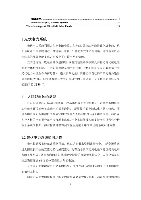
翻译原文 (4)Photovoltaic (PV) Electric Systems (4)The Advantages of Mitsubishi Solar Panels (5)1光伏电力系统光伏电力系统利用太阳能电池吸收太阳光线,并将这种能量转化成电能。
这个系统让广大家庭通过一种清洁,可靠,平静的方式来产生电能,这样就可以补偿将来的部分电能支出,也减少了对输电网的依赖。
太阳能电池一般是由经改进的硅,或者其他能够吸收阳光并将之转化成电能的半导体材料制成。
太阳能电池是相当耐用的(1954年在美国安装的第一个光伏电力系统至今仍在运营)。
绝大多数的生厂商都担保自己的产品的电源输出至少维持20年。
但大多数的有关太阳能研究的专家认为一个光伏电力系统至少能维持25到30年。
1.1 太阳能电池的类型目前有单晶硅,多晶硅和薄膜三种基本形式的光伏组件。
这些类型的电池工作效率都很好但单晶硅电池效率最好。
薄膜技术的电池以成本低为特色,而且伴随着太阳能电池板的发展它的效率也在不断地提高。
越来越多的生厂商以及各种各样的电池型号在当今市场上出现。
一个太阳能技术的支持者可以帮你分析各个系统的利弊,如此你就可以得到为你所用数十年的最佳的系统设计方案。
1.2光伏电力系统如何运作光电板通常安装在建筑物顶部,通过逆变器来引到建筑物中。
逆变器将通过太阳能板产生的直流电转化成交流电,而在当今美国交流电是向建筑提供电动力的主要形式。
朝南方向的太阳能板能使能量的收集效果最大化,大部分都是与建筑物顶部成60度的位置安放太阳能电池。
有关太阳能电池发电的更多的信息,可以查询Cooler Planet’s的《太阳能电池如何工作》。
朝南方向的太阳能板能使能量的收集效果最大化,大部分都是与建筑物顶部成60度的位置安放太阳能电池。
1.3 太阳能电池板与光伏建筑一体化太阳能电池板是用于捕获太阳光的平面板,他们以阵列的形式安装在建筑物顶部或者柱子上。
他们是传统的用于获得太阳能的阵列形式。
某变电所毕业设计的中英文对照(中英文翻译)
摘要XF 110KV变电所是地区重要变电所,是电力系统110KV电压等级的重要部分。
其设计分为电气一次部分和电气二次部分设计。
一次部分由说明书,计算书与电气工程图组成,说明书和计算书包括变电所总体分析;负荷分析与主变选择;电气主接线设计;短路电流计算;电气设备选择;配电装置选择;变电所总平设计及防雷保护设计。
二次部分由说明书,计算书与电气工程图组成。
说明书和计算书包括整体概述;线路保护的整定计算;主变压器的保护整定计算;电容器的保护整定计算;母线保护和所用变保护设计。
计算书和电气工程图为附录部分。
其中一次部分电气AutoCAD制图六张;二次部分为四张手工制图.本变电所设计为毕业设计课题,以巩固大学所学知识。
通过本次设计,使我对电气工程及其自动化专业的主干课程有一个较为全面,系统的掌握,增强了理论联系实际的能力,提高了工程意识,锻炼了我独立分析和解决电力工程设计问题的能力,为未来的实际工作奠定了必要的基础。
关键词: Ⅰ、变电所Ⅱ、变压器Ⅲ、继电保护AbstractXF county 110KV substation is an important station in this distract, which is one of the extremely necessary parts of the 110KV network in electric power system.The design of the substation can be separated in two parts: primary part and secondary part of the electric design。
The first part consists of specifications, computation book and Electrical engineering drawings about the design. The specifications has several parts which are General analysis of the station,Load analysis, The selection of the main transformer, Layout of configuration, Computation of short circuit;Select of electric devices, Power distribution devices, General design of substation plane and the design of thunderbolt protection.The second part also consists of specifications,computation book and electrical drawings about the design。
电气工程及其自动化本科毕业设计(论文)中英文对照翻译-电力系统
本科毕业设计(论文)中英文对照翻译院(系部)电气工程与自动化学院专业名称电气工程及其自动化年级班级03级2班学生姓名指导老师电力系统1 电力的技术特点电力具有独特的技术特点,这使得电力工业具有独特的行业特点。
1.无形性。
用户不能用人体感官直接察觉千瓦时的用电量。
2.质量。
供电质量可由供电连续性或供电可靠性、在标准电压等级下的电压均等性、交流电压频率的正确不变性来度量。
3.电力的贮存。
与大多数行业不同,电力部门必须随时根据用电的需求生产出电力来,因为电能无法贮存。
4.对供电负责。
电由电力部门输送到用户,因此必须对安全、可靠供电负责。
5.对公众的安全。
电力部门须对公众及其技术人员提供稳妥的保护。
2 电力系统的规划预期到电力部门的供电负荷将持续增长,电力系统的容量也持续增大。
远期规划主要是保证这种扩建在技术上是适宜的,在造价上是合理的,与增长模式是相符的。
远期规划者碰到的困难包括:不同地域和不同时间负荷增长的不确定性、新发明新技术发展的可能性。
优异的系统规划要努力做到全系统设计的最优化,而不能为了系统某部分造价的最小化而不顾其它部分的影响。
近年来,已经强调了规划和运行的经济性。
现在则越来越强调可靠性和环境方面的因素。
在作出规划前,须要仔细考虑许多因素:(1)设备的决策具有远期效应,这需要15—25年的预期和研究。
(2)有许多发电途径可选择:核电、基荷火电、中等规模燃气轮机发电或水电,以及大型、中型、小型电厂和各种形式的蓄能。
(3)有多种送电途径可选择,例如由交流或直流,架空线或地下电缆送电并有各种电压等级。
(4)规划决策受负荷管理技术和负荷模式的影响。
(5)有关因素存在不确定性。
如将来燃料价格货币的利率资金的来源设备的强迫停运率新技术环境的要求。
3 电力分配3.1 最初的分配系统发电厂和最后的各支路之间的分配线路叫做最初的分配系统。
在这两个电力系统之间传输有多种方法. 其中最常见的两种方法是辐射式和环绕式。
变电站毕业设计~外文翻译
山东理工大学毕业设计(外文翻译材料)学院:专业:学生姓名:指导教师:电气与电子工程学院电气工程及其自动化韦柳军孟繁玉Reliability modelling and analysis for SheffieldSubstation 220 kV upgrade projectCaroline Lee Transend, Networks Pty Ltd , TasmaniaDr Sudhir Agarwal,San Diego, California, USAABSTRACTThis paper describes the application of a defensible probabilistic process in reliability evaluation for Sheffield 220 kV Substation redevelopment project. Sheffield Substation is a hub of 220 kV transmission system in the North and North-West regions of Tasmania. It provides connection to West Coast and Mersey Forth hydro power stations and facilitates power transfers from these power stations to major industrial customers in George Town area and retail andindustrial loads in the North and North-West regions of Tasmania. Therefore, it is important that integrity of Sheffield Substation is protected as much as possible and consequences of unplanned outages minimised to prevent possible widespread system disturbances.Together with General Reliability from San Diego,California, Transend undertook the reliability evaluation of four redevelopment options for Sheffield Substation using SUBREL, substation reliability and TRANSREL, transmission system reliability programs.1.INTRODUCTIONTransend, as a Transmission Service Provider and Transmission Network Operator in Tasmania is responsible for providing reliable electricity supply and providing cost effective development solutions- 1 -of the transmission network. Transend has identified a need for a comprehensive and more objective process in justification of development projects from its capital works program. The need to combine customer reliability targets and economics to achieve cost effective development solutions has been long recognised. A hierarchical framework for overall power system reliability evaluation is presented in [1].Different design, planning and operating principles and techniques have been developed in different countries over many decades in an attempt to find balance between reliability targets and economic constraints [2].Following the reliability concept and principles, differentutilities applied different reliability criteria to justify projects from their capital works program. Reliability criteria can be viewed as conditions that should be satisfied by electricity generation, transmission and distribution systems in order to achieve requiredreliability targets. Reliability criteria usually fall into two categories: established numerical target levels of reliability (eg level of expected energy not supplied) and performance test criteria (eg N-1, N-2 incidents that the system has to withstand). An attempt to combine these two categories into one set of reliability criteria is currently underway in Tasmania [3]. The use of reliability criteria from the first category is the core of probabilistic reliability evaluation approach. The second category is a deterministic reliability evaluation approach. The usefulness of deterministic criteria and security standards in justification of projects from capital works program is challenged in [4]. Instead, an approach involving customers in decision making and simulating a realistic system operation and failure is commended. The basic steps suggested in proper reliability evaluations are based on complete understanding of the equipment and system behaviour including:• Understanding the way the equipment and system operate;- 2 -• Identify the situations in which equipment can fail;• Understand consequences of the failures;• Incorporate these events into the reliability model;•Use the available evaluation techniques tocalculate reliability indices and costs.With this understanding of the system behaviour probability theory is then only seen as a tool to transform this understanding into the likely system future behaviour.2. SELECTION OF EVALUATION TECHNIQUE AND SOFTWARE TOOLS There are two main categories of evaluation techniques[5]: analytical (stateenumeration) and Monte Carlo simulation. The advantages and disadvantages of both methods are discussed in [1].Analytical technique was chosen by Transend because of its usefulness in comparing different development options for network development projects. This approach was presented also in the Electricity Supply Association of Australia Guidelines for Reliability Assessment Planning [6]. Consequently, decision was made to acquire SUBREL, and TRANSREL, substation reliability and transmission system reliability programs from General Reliability,USA.2.1. SUBREL - SUBSTATION RELIABILITYPROGRAMSUBREL is a computer program which calculates reliability indices for an electricity utility substation and generating station switchyard [7]. The methodology used to analyse impact of substation generated outages on overall system reliability performances has been described in [8]. The program models the following outage events, including all required subsequent automatic and manual switching operations:1. Forced outage of any substation component:- 3 -• Breaker• Transformer• Bus Section• Disconnector2. Forced outage of an incoming line.3. Forced outage overlapping a maintenance outage for substation equipment or an incoming line.4. Stuck breaker (failure to open when needed to clear the fault). SUBREL calculates the following load point indices:• Frequency of Interruption (per year)• Number of Circuits Interruptions (per year)• Outage Duration (minutes per outage)• Annual Total Outage Duration (minutes per year)• Customer Minutes of Interruption CMI (per year)• Expected Unsupplied Energy (EUE) (kWh per year)• Expected Outage Cost ($ per year)SUBREL also calculates the following substation or totalsystem indices:• SAIFI, System Average Interruption Frequency Index• SAIDI, System Average Interruption Duration Index• CAIDI, Customer Average Interruption Duration Index• ASAI, Average Service Availability Index• EUE, Expected Unsupplied Energy (kWh per year)- 4 -• Expected Outage Cost ($ per year)SUBREL generates a list of substation generated outages that can be used further by TRANSREL to analyse impact on overall system reliability performance.2.2. TRANSREL – TRANSMISSION SYSTEM RELIABILITY PROGRAMTRANSREL uses contingency enumeration of transmission contingencies to evaluate power network reliability. It is designed to aid electric utility system planners for reliability assessment of bulk power systems. The process involves specifying contingencies (outages of transmission lines and station originated outages) and performing load flow analysis to determine system problems such as circuit overloads, low/high bus voltages, bus separation or islanding. Using the probability, frequency and duration of the contingencies evaluated, indices of system problems as measures of system unreliability are calculated. Both post contingency and post remedial action indices can be calculated. If no remedial actions are taken to alleviate a problem, the post contingency indices may provide a pessimistic assessment of system reliability. If remedial actions such as generation redispatch, switching of facilities, curtailment of load alleviates some of the system problems, the post remedial action reliability indices provide a more realistic measure of system performance. The amount of load shedding is used as an indicator of contingency severity or system capability to withstand contingencies. Using probabilities of contingencies, expected load curtailment at buses can be calculated as reliability indices. TRANSREL was used with load flow program, PTI PSS/E to examine the impact of an outage on system performance. The types of failures identified for checking the impact of a contingency on system performance are: Transmission circuit overloads - by comparing flows based on the load flow solution with user- 5 -selected circuit ratings; Bus voltage violations - by checking bus voltages against high and low voltage limits, or maximum allowable voltage deviation from the base case; Load curtailment - by tabulating the amount of load curtailed as a result of system failure;Load flow divergence - by tabulating the bus mismatches above a predefined tolerance. TRANSREL computes reliability indices using a contingency enumeration approach, which involves selection and evaluation of contingencies, classification of each contingency according to specified failure criteria, and computation of reliability indices. Reliability indices include frequency, duration and severity (overloads, voltage violations, load curtailed, and energy curtailed). Both system and bus indices are calculated.3.SUBREL AND TRANSREL APPLICATION FOR SHEFFIELD 220 KV SUBSTATION Sheffield Substation is a hub of 220 kV transmission system in the North and North-West regions of Tasmania. As shown on Figure 1, it provides connections from the West Coast and Mersey Forth hydro power stations to the rest of the system. In addition, it supplies Aurora Energy customers in North and North-West regions and major industrial customers in the George Town area.During winter months, from May to September, the amount of energy supplied through and transferred from Sheffield Substation can reach more than 50% of the energy supplied to the rest of the system as shown in Figure 2.As such, Sheffield Substation has been recognized as a vulnerable point in the Tasmanian power system. The total loss of Sheffield Substation during times of large power transfer from West Coast of Tasmania to the rest of the system could possibly lead to a large system disturbance in Tasmania. With the present Sheffield Substation 220 kV layout, the total loss of Sheffield Substation can be caused by a single element failure.- 6 -3.1. DEVELOPMENT OPTIONS ANALYSEDThe need to redesign the existing substation 220 kV layout has been recognised long time ago. The following three options have been selected for detailed modeling and analysis:Option 1: Triple busbar arrangementOption 2: Full breaker and a half and double breaker arrangement Option 3: Partial breaker and half and double breaker arrangement These options were compared against the existing 220 kV busbar design (Do Nothing option).A brief description of each of these options is as follows:3.1.1. DO NOTHING OPTION- 7 -The “Do nothing option” represents the existing 220 kV busbar arrangement at Sheffield Substation. The existing 220 kV Sheffield Substation has had some major changes since substation commissioning and installation of two autotransformers for the North and North-West regions of Tasmania supply in 1967. The substation 220 kV busbar arrangement is double, strung busbar arrangement with one bus coupler. In normal system configuration main bus coupler A752 is closed, 220 kV“S” by pass bus and second bus coupler S752 are not in service. The schematic diagram of this option is shown below. Total number of circuits connected at Sheffield Substation is 12. Total number of circuit breakers is 14 (12 plus 2 bus couplers). Sheffield Substation is a main supply point to the North-West Region of Tasmania. Total load in the region is around 260 MVA. The fault on bus coupler A752 will result in the loss of both busbar A and B and therefore loss of more than 50% of supply in Tasmania during winter season leading to a blackout in the North-West region.West Coast region will loose synchronism with the rest of the system, experience over frequency and will be islanded. The rest of the system will experience.Under frequency and significant amount of load must be shed to prevent total blackout. In the case of 220 kV busbar A fault at Sheffield Substation, two elements supplying the North-West region which are the Sheffield–Burnie 220 kV line and autotransformer T1, would be lost. During high winter load the remaining autotransformer T2 will be overloaded and tripped on overload conditions. This will lead to total blackout in the North-West region of Tasmania. In the case of 220 kV busbar B fault, two elements supplying George Town which are the Sheffield–George Town No 1 transmission line and Sheffield–Palmerston transmission line will be lost. During high winter loads the remaining Sheffield–George Town No 2 line will tripped on overload.- 8 -This will cause significant change in network impedance with requirement to shed load at major industrial customers at George Town. Consequently, this will produce excessive generation connected at Farrell and Sheffield, which can move the system towards unstable operation and cascade of events with possible blackout in the North and North West regions of Tasmania.3.1.2. OPTION 1-TRIPLE BUSBAR ARRANGEMENTThe schematic diagram of this option is shown below In comparison with “do nothing option” this option proposes to use the spare S752 circuit breaker and upgrade a nd energise “S” bypass bus to full size. The existing 12 circuits will be spread across the three busbars. Only one additional 220 kV circuit breaker is required in this option. The total number of circuit breakers in this option is 15.3.1.3. OPTION 2 - FULL BREAKER AND A HALF AND DOUBLE BREAKER ARRANGEMENT The schematic diagram of this option is shown below. This option includes- 9 -creating double breaker and breaker and half arrangements. Breaker and a half arrangement is proposed between Hydro Tasmania’s C ethana power station and autotransformer T1; and Lemonthyme power station and autotransformer T2. The total number of circuit breakers in this option is 19.3.1.4. OPTION 3 - PARTIAL BREAKER AND A HALF AND DOUBLE BREAKER ARRANGEMENTThe schematic diagram of this option is shown below. The main difference in comparison with option 2 is thatthere is no breaker and half arrangements between Hydro Tasmania’s Cethana power station and autotransformer T1; and Lemonthyme power station and autotransformer T2. The establishment of breaker and a half arrangements between these circuits could have as a consequence increase in connection charges for Hydro Tasmania for middle breakers, which needs to be discussed and agreed with this customer. Total number of circuit breakers in this option is 17.3.2. RESULTSIn this study, the following outages are examined:• n-1 forced outage of a station component including transmission lines and transformers• n-1 maintenance overlapping n-1 forced outages•breaker stuck condition following a fault. For a fault on line, transformer, bus or a breaker, only those breakers will be considered for being in a stuck condition that are supposed to trip to clear the fault. In this case back up protection will clear the fault.Apart from the above outages examined, higher order of outages can also be considered and simulated in the programs, however the probability and frequency of- 10 -their occurrence is quite low. Based on the Transend outage data, it was decided that the above settings should capture most of the credible outage events. The number of events for each of the options is given in the following table. These events are generated by the program to study their impact on substation performance. For each event, the program calculates the probability, frequency and duration. Using the connectivity model, it also computes the amount of loss of load and energy for a load point and for the overall substation. Using a linear flow method it checks if the load can be supplied without violating the ratings of any component. The number of outage events enumerated and examined by the SUBREL program depends on the number of components in a station and the program settings. If more components are added to a station, their exposure to failures also increases. To select an optimal design, a balance between the redundancy provided by adding a component (breaker or a busbar) and the increased exposure should be kept in mind. As seen from the tables above, the number of outage events for options 1,2 and 3 is higher than for the existing configuration since these options have more breakers and buses in their suggested configurations. There is no event that causes the complete loss of load in the area (including Burnie, Sheffield and George Town substations in the model) in any of the options. However there are events in each option that will cause partial loss of load. Option 2 has the lowest number of events causing loss of load while the existing configuration has the highest number of events causing loss of load. Reliability indices computed by SUBREL program for each of the option is given in the table below. These indices are computed using the load Probability Density Function (PDF) as unity. PDF of unity means that the load is same throughout the year. The widely used reliability indices such as SAIFI, SAIDI, CAIDI, ASAI,and EUE are computed by the program.Outage costs are calculated based on calculated expected- 11 -unsupplied energy (EUE) and value of lost load applied to particular customer groups. A comprehensive analysis of value of lost load for different customer groups has been undertaken by Monash University for Victorian utilities [9]. Based on the table above it is clear that option 1 – triple busbar arrangement, has lowest outage costs. Based on the list of substation originated outages generated by SUBREL, TRANSREL program was used to indicated consequences on the overall system performances. The voltage violations were encountered only for option2 in 9 simulation events. There were few contingencies for which solution did not converge. For these contingencies, a potential exists that the system will face major problems including a collapse. The system stress and its response will, of course, depend on the system conditions present at the time outages. There are four events for Option 1 that result in non-convergence of the power flow. The probability of these non-convergence cases for Option 1 is 0.0026 which means that there is a potential that exists that the system may collapse once every 400 years. This is a very low likely event and during this time the system is likely to go through several changes. It should also be noted that in this analysis no remedial actions are included. With remedial actions, operators may be able to avoid such a situation.4. CONCLUSIONSThe implementation and application of a probabilistic based planning for selecting a substation configuration provides quite useful information to an engineer in deciding the best option. The use of both SUBREL and TRANSREL programs for Sheffield Substation study has sufficiently demonstrated that it is important to examine all credible outage scenarios that are not possible to do manually. Quantitative indices computed by these programs provide an objective assessment of various- 12 -options considered. For transmission substations it is important that only SUBREL analysis may not provide the complete information. Without performing a TRANSREL analysis,it is likely that the risk posed by a configuration may not be correctly assessed from the overall system point of view. For the Sheffield Substation the triple busbar arrangement (Option 1) is the cheapest option, easy to implement, and reliability indices for Sheffield Substation are the best in this option. The low probabilities divergent cases can be resolved with appropriate remedial actions in place, including, generation rescheduling, voltage support and load shedding.REFERENCES[1] Billinton, R. and Allan, R.N.,:”Power-system reliability in perspective”, IEE Electronic and Power, pp. 231-236, March 1984.[2] “Power System Reliability Analysis. Application Guide,” CIGRE WG03 of SC 38,Edited by Lesley Kelley-Regnier, 1987.[3] “Transmission Network Security and Planning Criteria-draft”, Office of Tasmanian Energy Regulator, August 2005.[4] Al lan, R.N., and Billinton, R.:”Probabilistic methods applied to electric power systems-are they worth it?”,Power Engineering Journal, pp.121-129, May 1992.[5] Billinton, R. and Allan, R.N.,:” Reliability Evaluation of Power Systems”, Pitmans Books, New Yor k and London, 2nd edition, 1996. [6] “ESAA Guidelines for Reliability Assessment Planning,”, November 1997.[7] “Subrel-Substation Reliability Program User Manual”, General Reliability, San Diego, CA, 2002.- 13 -[8] Agarwal, S.K., and Anderson, P.M..: “Effect o f Station Originated Outages on Bulk Power System Reliability, ”, Cigre Symposium, S 38- 91, Montreal, 1991.[9] Monash University,:” Study of the Value of Lost Load” , Study conducted for the Victorian Power Exchange (VPX) company,Melbourne,2000.- 14 -谢菲尔德变电站220千伏升级项目的可靠性建模与分析创见网络私人有限公司,塔斯马尼亚阿加瓦尔博士,美国加利福尼亚州圣迭戈摘要本文介绍了在可靠性评估中的应用一个可防御概率过程谢菲尔德220千伏变电站重建项目。
工厂供电毕业设计
某机械厂供配电一次系统设计摘要工厂供电是将从电力系统中获得的电能经过合理的传输变换,分配到工厂的车间里的用电设备上。
伴随着社会的发展,工厂对电能的质量,供电可靠性以及经济性等要求也越来越高。
工厂供电设计是否完善不仅影响工厂的生产,而且也反映到工厂供电的可靠性与安全生产上,它与企业的经济效益,设备安全运行以及工人的人身安全密切相关,因此,搞好工厂供电工作对于整个工厂的生产发展有十分重要的意义。
本设计是对工厂供电一次部分的设计,对工厂的负荷计算,短路电流计算,变电所变压器的选择,校验,无功补偿等进行了设计说明,该设计从全局出发,按照负荷性质,用电容量等做出了合理的设计。
关键词:配电线路变压器负荷短路电流电气设备The Design of Primary System of Total Step-down SubstationABSTRACTPower supply in factory is mean to electricity energy which is obtained from the power system is transferred reasonable, and it is distributed to the electric device of the factory floor. With the development of the society, the quality, reliability and economy demands of the electricity energy were increasing to the factory. Whether the design of the factory electricity supply is perfect not only affect the plant's production, but also reflects the reliability of power supply to the factory and safety, it is closely related to the economic benefit of enterprises, equipment, safe operation and safety of workers, it is important for the development of production for doing a good job of the factory power supply work.This design is a part of power plant design, including of the plant load calculation, short circuit current calculation, and the choice of transformer substations, verification, reactive power compensation for the design specification, it make a reasonable designfollowed the load nature and electricity capacity ,standing on the overall situation.KEY WORDS: distribution list ,supply transformer ,power load ,short-circuit co ntact ,electric apparatus目录前言 (1)第1章负荷计算 . (2)1.1 负荷概述 (2)1.2 用电设备组计算负荷的确定 . (3)第2章变压器选择 . (9)2.1 变配电所选址 (9)2.2 车间变电所变压器选择 . (10)2.3 无功补偿及工厂总降压变电所设计 . (16)第3章变电所主接线设计 . (20)3.1 电气主接线选择及运行方式 . (20)3.2 短路电流计算 (22)第4章高压电网一次设备选择 . (28)4.1 35kV架空线选择 (28)4.2 10kV电缆选择 (29)4.3 母线选择 (32)4.4 电气设备选择校验 . (33)4.5 高压开关柜选择 . (39)第五章防雷及过电压保护 . (41)5.1 避雷器 (41)5.2 避雷器的选择计算 . (41)5.3 变电所的防雷保护 . (43)结论 (44)谢辞 (45)参考文献 . (46)附录 (47)外文资料翻译 . (51)前言众所周知,电能是现代工业的主要能源和动力。
毕业设计--供电系统[管理资料]
![毕业设计--供电系统[管理资料]](https://img.taocdn.com/s3/m/a11d6883f242336c1fb95e20.png)
柳州职业技术学院毕业设计(论文)书题目: 柳职院机加工实训基地供电系统设计系别: 电子电气工程系专业: 供用电技术年级: 2 0 0 4 级姓名:指导教师:完成日期: 2007 年 3 月 20日前言本设计为柳州职业技术学院04级毕业生的毕业论文,是根据柳州职业技术学院毕业生的毕业论文的规定和指导老师的要求编写的,充分体现了柳州职业技术学院毕业生的学习能力和实践能力。
电能是工业企业生产的主要能源和动力,它也有利于我们学院教学质量的提高。
但如果供电的要求达不到安全,可靠,优质和经济,就会影响我们学院的教学质量,和经济损失。
因此,搞好本次的设计是非常重要的。
本设计共分十五章。
第一章到第十四章介绍了客观环境、设计思路、方案以及预算等等。
第十五章谢辞,参考文献。
本设计是设计者查阅了大量相关书籍和资料,并结合多年学习经验与实践经验的基础上编写而成的。
针对机加工实训楼的供电系统的设计和运行的需要,在概述供电基本理论和基本知识的同时,着重供电系统的设计和短路的计算,加强了理论知识与实践能力的联系。
地理位置,地貌,环境条件,风力气候及雨水,环境污染,雷击率等。
机加工实训楼坐落在一个半山腰,背靠山,前面也是山,整个建筑物座西向东,环境污染很少,且雷击率少。
本设计在设计时得到了系主任唐冬雷和陈声轩老师的热心指导,在此一并表示衷心的感谢!本人的知识水平有限,设计中难免有错误和不妥之处,望请读者批评指正。
设计者: ***目录第一章自然条件 (4)第二章配电所地址及布置 (5)第三章负荷统计 (6)第四章变压器容量和台数选择 (13)第五章配电所高低压的主接线方案 (16)第六章电气主接线 (20)第七章高低压元器件的选择 (21)第八章电能的计量与测量 (22)第九章电缆线或架空线结构和敷设 (25)第十章导线和电缆线的选择 (26)第十一章车间动力平面图布置及电气照明 (29)第十二章电光源和灯具的选择 (30)第十三章防雷与接地 (32)第十四章经济概算及经济分析 (34)第十五章谢辞 (35)参考文献 (36)第一章自然条件1地理位置,地貌,环境条件,风力气候及雨水,环境污染,雷击率等。
设计3千瓦风光互补离网供电系统3G基站毕业论文外文文献翻译及原文
毕业设计(论文)外文文献翻译文献、资料中文题目:设计3千瓦风光互补离网供电系统3 G基站文献、资料英文题目:文献、资料来源:文献、资料发表(出版)日期:院(部):专业:班级:姓名:学号:指导教师:翻译日期: 2017.02.14目录1.简介 (2)2. 3G基站的基本结构和工作原理基站的3KW风光互补独立电力系统 (3)3.风力发电和风光互补发电及其分析 (3)3.1风光互补混合动力 (3)3.2风电及其控制 (4)3.3太阳能及其跟踪系统 (5)3.4参数分析 (5)4.风光电源及其控制 (6)4.1风电追踪及电流控制 (6)4.2光电跟踪和电流控制 (7)4.3风和光共同供电 (7)4.4太阳能电池板参数分析 (7)5.仿真与实验结果 (7)5.1仿真实验 (7)5.2实验结果 (8)6.结论 (9)设计3千瓦风光互补离网供电系统3 G基站摘要本文主要研究3G基站的3千瓦风光互补系统的结构设计和控制系统设计。
此系统并入3G基站达到节省电力的目的是为了充分保证基站在任何情况下能正常供电。
风光互补系统包括三个部分:第一部分,在风力发电系统中,由整流器,转换器等组成;第二部分主要由太阳能电池面板发电系统、风力发电系统和风光互补发电系统;第三部分是单相电源逆变器、风能和太阳能电池面板电源相互连接形成3G基站需要的电能,然后进入单相电源逆变器,逆变成220伏,50赫兹的电来供应3G基站。
在各种天气状况下,风能和太阳能可以互补。
通过模拟不同的天气、加载和模拟单相逆变器实验,证明风光互补系统是有效可行的。
关键词——风能,太阳能,风光互补发电,boost变换器;供给逆变器1.简介随着移动通信的发展,特别是3G移动通信的发展,3G基站电源日益成为边远地区必须解决的问题。
目前,在偏远地区,3G基站使用太阳能供电的辅助电源供应或由风力发电装置供应。
配套的太阳能电力供应3G基站电源,但这只能解决电力网格问题,不可靠的电力供应和大多数在偏远地区的3G基站,由于高成本的网格站电和沙尘暴由引起的我国西北地区大型太阳能面板往往可以很容易被灰尘阻挡太阳,所以在西北地区一旦有大风,太阳能供电将有一定的使用缺陷。
供电工程毕业设计
1负荷等级确定与供电电源1.1负荷等级确定一级负荷: 一层卖场照明、商品街照明、二层卖场照明、三层照明、室外消防泵房、消防排烟风机。
二级负荷: 库房区照明负荷、空调冷冻机房、空调用泵房、两台货梯、肯德基动力负荷、一层食品加工区、商品街动力负荷。
三级负荷: 户外广告路灯、广告灯箱、停车场照明、一层自动扶梯、二层自动扶梯。
一级负荷应采用二路高压电源供电。
二级负荷采用双电缆线路,一用一备,变压器低压侧的母联采用自投装置。
三级负荷对供电无特殊要求,但供电线路上的负荷尽量使三相平衡。
1.2供电电源采用两路10KV电源进线,一用一备形式供电2 负荷计算与无功补偿2.1计算公式:有功计算负荷 c d N P K P = 无功计算负荷 tan c c Q P ϕ= 视在计算负荷 cos cc P S ϕ=计算电流c I =其中(U N =0.38 Kv )2.2负荷计算列表2.3 无功补偿本工程选择低压集中补偿,并且选定并联电容器来进行无功补偿。
2.4总计算负荷无功补偿容量:补偿前低压侧:21730.9c S KVA = 21418.4c P K w = 所以:()()'2tan tan 1418.4tan arccos0.82tan arccos0.92385.8varNC c Q P K ϕϕ=-=⨯-=由以上计算的无功补偿容量初步选定容量为:400Kvar 补偿后低压侧:'21536.98c S KVA ==='20.010.011536.9815.37T c P S Kw ∆==⨯='20.050.051536.9876.85var T c Q S K ∆==⨯=121418.9815.371433.77c c T P P P KW =+∆=+=12'99240076.85668.85var c c T Q Q Q K =+∆=-+=总计算负荷:1851582.11c S K V A ==191.34c I A ===3 变(配)电所所址选择与结构型式3.1 所址选择根据建筑电气设计规范,所址选择参照以下条件1、所址选择应以主变压器为中心,要求变压器运输时进出口及消防通道通行方便;2、高、低压配电装置进出配线方便合理;3、尽量靠近负荷中心(10KV中压变电所低压配出线半径以不超过400m为宜);4、避开易燃易暴及严重污染地区;5、注意对公用通讯设施的抗干扰措施;6、独立变配电所的变压器室应优先考虑北入口方案为最佳方案;本工程变电所作为室内变电所,位于超市一层,有人值班。
- 1、下载文档前请自行甄别文档内容的完整性,平台不提供额外的编辑、内容补充、找答案等附加服务。
- 2、"仅部分预览"的文档,不可在线预览部分如存在完整性等问题,可反馈申请退款(可完整预览的文档不适用该条件!)。
- 3、如文档侵犯您的权益,请联系客服反馈,我们会尽快为您处理(人工客服工作时间:9:00-18:30)。
某钢铁企业变电所保护系统及防护系统设计1 绪论1.1 变电站继电保护的发展变电站是电力系统的重要组成部分,它直接影响整个电力系统的安全与经济运行,失恋系发电厂和用户的中间环节,起着变换和分配电能的作用,电气主接线是发电厂变电所的主要环节,电气主接线的拟定直接关系着全厂电气设备的选择、配电装置的布置、继电保护和自动装置的确定,是变电站电气部分投资大小的决定性因素。
继电保护的发展现状,电力系统的飞速发展对继电保护不断提出新的要求,电子技术、计算机技术与通信技术的飞速发展又为继电保护技术的发展不断地注入了新的活力,因此,继电保护技术得天独厚,在40余年的时间里完成了发展的4个历史阶段。
随着电力系统的高速发展和计算机技术、通信技术的进步,继电保护技术面临着进一步发展的趋势。
国内外继电保护技术发展的趋势为:计算机化,网络化,保护、控制、测量、数据通信一体化和人工智能化。
继电保护的未来发展,继电保护技术未来趋势是向计算机化,网络化,智能化,保护、控制、测量、数据通信一体化发展。
微机保护技术的发展趋势:①高速数据处理芯片的应用②微机保护的网络化③保护、控制、测量、信号、数据通信一体化④继电保护的智能化1.2本文的主要工作在本次毕业设计中,我主要做了关于某钢铁企业变电所保护系统及防护系统设计,充分利用自己所学的知识,严格按照任务书的要求,围绕所要设计的主接线图的可靠性,灵活性进行研究,包括:负荷计算、主接线的选择、短路电流计算,主变压器继电保护的配置以及线路继电保护的计算与校验的研究等等。
1.3 设计概述1.3.1 设计依据1)继电保护设计任务书。
2)国标GB50062-92《电力装置的继电保护和自动装置设计规范》3)《工业企业供电》1.3.2 设计原始资料本企业共有12个车间,承担各附属厂的设备、变压器修理和制造任务。
1、各车间用电设备情况用电设备明细见表1.1所示。
表1.1 用电设备明细表2、负荷性质本厂大部分车间为一班制,少数车间为两班或者三班制,年最大有功负荷利用小时数为h2300。
由于锅炉房供生产用高压蒸汽,停电会使锅炉发生危险。
而且该厂距离市区较远,消防用水需厂方自备。
因此,锅炉房供电要求具有较高的可靠性,负荷性质属于二级负荷,其余车间均为三级负荷。
3、变电所数量及供配电系统电压确定(1)根据本企业的厂区范围和负荷分布情况,在该厂区设置一个总降压变电所,可满足本企业的供电要求。
(2)供电电压确定。
根据当地电网的供电电压等级,同时考虑用电设备的负荷容量和供电距离等因素,与电力部门协商确定供电电压为kV35。
(3)配电电压选择。
高压配电电压的选择,主要取决于高压用电设备的电压及其容量、数量等因素。
考虑到该厂的规模不大,采用kV10作为该企业用电设备配电电压比较经济合理。
4、供电电源条件当地供电部门可提供两个供电电源,供设计部门选定:(1)待设计总降压变电所的主电源由上一级某区域变电站(kV35架空线220)提供电源,kV/35引入,作为工作电源进线,此站距企业南侧km5.4。
(2)另一路10kV电源作为备用电源,从某kV35变电所经电缆线引入该企业,此所距企业南10/侧km4(3)总降压变电所引入两路电源进线,分别在两路进线电源分别设有计量电能的高压计量柜。
(4)上一级某区域变电站配备有定时限过电流保护和电流速断保护,定时限过电流保护整定的动作时间为1.5s。
5、该地区气象及地质资料(1)气象资料,年最高气温C︒20,年最低气温C-40,年最热月平均最高气温︒︒40年平均气温C20,常年主导风向为南风,年雷暴日28,最热月地下m8.0处平均温度C︒35,年最热月平均气温C︒C︒数h32。
(2)地质水文资料,平均海拔m3-。
500,地层以砂粘土为主,地下水位m52 负荷计算及变压器选择2.1 负荷计算3710.5A B图2.1供电系统电力负荷计算图由表1.1计算各点计算负荷1.电修车间:查表得需用系数k x1=0.34,cosφ=0.60,tanφ=1.33P30=P N1×k x1=505×0.34=171.70(KW)(2.1)Q30=P30×tanφ=171.7×1.33=228.93(Kvar)(2.2)(KV•A)(2.3)S30I30=S/ 3 U N=16.50(A)(2.4)2.机械加工车间:查表得需用系数k x2=0.24,cosφ=0.63,tanφ=1.23P30=P N2×k x2=786×0.24=188.64(KW)(2.5) Q30=P30×tanφ=188.64×1.23=232.03(Kvar)(2.6)(KV•A)(2.7)S30I30=S/ 3 U N=16.94(A)(2.8) 3.新产品试制车间:查表得需用系数k x3=0.50,cosφ=0.8,tanφ=0.75P30=P N3×k x3=634×0.5=317.00(KW)(2.9) Q30=P30×tanφ=317.00×0.75=237.75(Kvar)(2.10)(KV•A)(2.11)S30I30=S/ 3 U N=22.88(A)(2.12) 4.原料车间:查表得需用系数k x4=0.3,cosφ=0.85,tanφ=0.62P30=P N4×k x4=414×0.3=124.20(KW)(2.13) Q30=P30×tanφ=124.20×0.62=76.97(Kvar)(2.14)(KV•A)` (2.15)S30I30=S/ 3 U N=8.44(A)(2.16) 5..备件车间::查表得需用系数k x5=0.30,cosφ=0.65,tanφ=1.17P30=P N5×k x5=262×0.30=78.60(KW)(2.17) Q30=P30×tanφ=78.60×1.17=91.89(Kvar)(2.18)(KV•A)(2.19)S30I30=S/ 3 U N=6.98(A)(2.20) 6.锻造车间:查表得需用系数k x6=0.35,cosφ=0.68,tanφ=1.08P30=P N6×k x6=350×0.35=122.50(KW)(2.21) Q30=P30×tanφ=122.50×1.08=132.30(Kvar)(2.22) S(KV•A)(2.23)30I30=S/ 3 U N=10.40(A)(2.24) 7..空压站:查表得需用系数k x7=0.35,cosφ=0.68,tanφ=1.08P30=P N×7k x7=622×0.75=466.5(KW)(2.25) Q30=P30×tanφ=466.5×1.08=620.13(Kvar)(2.26)(KV•A)(2.27)S30I30=S/ 3 U N=35.91(A)(2.28) 8..大线圈车间:查表得需用系数k x8=0.55,cosφ=0.87,tanφ=0.57P30=P N8×k x8=335×0.55=184.25(KW)(2.29) Q30=P30×tanφ=184.25×0.57=104.42(Kvar)(2.30)(KV•A)(2.31)S30I30=S/ 3 U N=12.23(A)(2.32) 9.成品试验站:查表得需用系数k x9=0.40,cosφ=0.80,tanφ=0.75P30=P N9×k x9=290×0.40=130.5(KW)(2.33) Q30=P30×tanφ=130.5×0.75=97.88(Kvar)(2.34)S(KV•A)(2.35)30I30=S/ 3 U N=9.42(A)(2.36) 10.加压站、转供负荷:查表得需用系数k x10=0.45,cosφ=0.78,tanφ=0.80P30=P N10×k x10=256×0.45=115.20(KW)(2.37) Q30=P30×tanφ=115.20×0.80=92.40(Kvar)(2.38) S(KV•A)(2.39)30I30=S/ 3 U N=8.53(A)(2.40) 11.大型集中负荷:查表得需用系数k x11=0.80,cosφ=0.75,tanφ=1.33P30=P N11×k x11=1600×0.80=1280(KW)(2.41) Q30=P30×tanφ=1280×1.33=1712.4(Kvar)(2.42) S(KV•A)(2.43)30I30=S/ 3 U N=98.54(A)(2.44) 12.锅炉房:查表得需用系数k x12=0.72,cosφ=0.8,tanφ=0.75P30=P N12×k x12=369×0.72=265.88(KW)(2.45) Q30=P30×tanφ=265.88×0.75=199.26(Kvar)(2.46) S= (KV•A)(2.47)30I30=S/ 3 U N=29.05(A)(2.48) 13.计算企业总降压变电所10kv母线上的计算负荷(即B点)P30(B)=K P×∑P=0.9×3444.97=3100.5(KW)(2.49)Q30(B)=K Q×∑Q=0.9×3826.36=3443.7(Kvar)(2.50)S= (KV·A)(2.51)I= S30(B)N)=267.8(A)(2.52)14.计算企业总降压变电所高压进线计算负荷(即A点)P30(A)=P30(B)+ΔP B=P30(B)+0.012S30(B)=3156.1(KW)(2.53)Q30(A)=Q30(B)+ΔQ B=Q30(B)+0.06S30(B)=3721.7(Kvar)(2.54)S= (KV·A)(2.55)= S30(A)N)=80.5(A)(2.56)I2.2 变压器选择2.2.1 选择主变压器台数选择变压器台数时应满足用电负荷对供电可靠性的要求。
对供有大量一二级负荷的变电所,应采用两台变压器,以便一台变压器发生故障和检修时,另一台变压器能对一二级负荷继续供电;对只有二级负荷而无一级负荷的变电所,可采用一台变压器,但须自备备用电源,本设计即采用后一种方案。
所以选择一台变压器供电。