BYF背压阀使用说明书
BIFFI icon2000电动阀门操作手册
重要:
检查名牌上“环境温度范围”与外界环境温度一致。
2. 从执行机构上拆下联轴器
随机提供的轴套是装配在驱动轴套上,但可能没有加工。为了加工轴套,需把轴套从壳体上拆 下,同时拆下联轴器上的固定螺钉。
10
“ICON2000”电动执行机构
安装及维修手册
现在可以在衬套上加工出连接需要的轴孔。同样的步骤也用于维修。
重点:
重装轴套前,确认与阀杆配合公差正确。对螺纹连接轴套,须用螺纹规检 查,或将轴套旋入需驱动阀门的阀杆,检查其与阀杆没有过分磨擦。
2.1.2 重装内部零件:
建议用合适的溶剂清洗拆下零件,然后用压缩空气干燥,确认没有金属屑或异物,然后将所有 部件涂一层薄的润滑脂。(润滑脂牌号:见第 5 章)
11
用合适卡钳拆下卡环 拆下碳钢止推环; 取出衬套并按配合需要加工。
“ICON2000”电用合适的溶剂清洗拆下零件,然后用压缩空气干燥,确认没有金属屑,然后涂一层薄的润滑
脂。(润滑脂牌号:第一部分第四章) 按拆下时的相反顺序装配内部零件,然后安装到减速器上。如后描述。
Copyright by BIFFI Italia. All rights reserved. A tyco INTERNATIONAL LTD. COMPANY
12
“ICON2000”电动执行机构 安装及维修手册
注意:
除执行机构上安装的手轮和离合杆外,不要用其它工具(如铁棒、轮扳手、管 扳手等)操作手轮和离合杆,否则会对造成人身严重伤害和/或执行机构或阀门 的损坏。
Диксон Bayco DBFVAO210 应急阀门说明说明书

Dixon1300 134 651******************************.au.auEmergency Foot Valves are installed in the floor of each tanker compartment and allow the inflow and discharge of fluid during the loading and unloading process of road tankers.Dixon Bayco’s DBFVAO210 Emergency Valve features sequential air actuation for easy pneumatic circuit interlock integration and an integral shear groove an inward opening poppet, which is designed to retain tanker contents in the event of an incident.Constructed in cast aluminium and easily removed for maintenance, the Dixon BaycoEmergency Valve features externally removable pneumatic ram and replaceable poppet with bonded seal which will not only provide years of service but also help reduce running costs over the lifetime of product ownership. Including a manual override and top operable via Dixon’s DBLWKIT Lift wire kit, the DBFVA0210 features the same flange to flange dimensions of other commonly used brands of EmergencyValves found in Australia, hence it is designed to retrofit directly to existing flanges. Also available from Dixon are weld in companion tank and outlet flanges and Baylast™ to suit for both new tanker builds and complete refits.As with other Dixon Bayco components the DBFVA0210 is supplied with our proprietaryBaylast™ seals which are suitable for use with all fuels found in the current market including ethanol and ethanol blends from E10 through E100, Bio-Diesels from B2 through B100 as well as regular unleaded and diesel fuels.Bayco Emergency ValveTop Operator Camlift DBCO402Fill Tube Adaptor Kit DBFA80Dip Tube Adaptor Kit DBDA80Dip Fill Tube Steady DBTS80Dip Tube Guide DBTG80Outlet Flange Gasket 40418BLTank Flange Gasket 40417BLLift Wire Kit DBLWKIT。
安全阀、背压阀设定及流量标定流程

安全阀、背压阀设定及流量标定流程
安全阀、背压阀压⼒设定流程,流量标定设定
注意:设定过程应先设定安全阀,再设定背压阀。
1. 打开球阀1(见附图),同时关闭球阀2、3,并将安全阀,背压阀上部的压⼒调节螺栓逆时针完全松开,即安全阀,背压阀设定压⼒全部为零。
2. 启动计量泵。
介质此时应该从安全阀泄压管路流出。
3. 顺时针调整安全阀上部螺栓,增加压⼒,同时观察压⼒表,直到压⼒表显⽰读数为现场实际⼯作压⼒的1.15—1.2倍左右(注意:压⼒表读数不能⾼于计量泵最⼤额定压⼒)。
4. 打开球阀3。
5.顺时针调整背压阀上部螺栓,增加压⼒,同时观察压⼒表,直到压⼒表显⽰读数为
1.5Bar左右(注意:具体背压值可视现场情况⽽定,但要低于安全阀设定压⼒)。
6.关闭计量泵。
安全阀、背压阀压⼒设定完毕。
流量标定流程
1.打开球阀1、3。
2. 启动计量泵。
3.将计量泵冲程调节旋钮调到100%,确定管路中已没有空⽓存在,流量已达到稳定。
4.停泵。
打开球阀2,直到标定柱内充满介质后关闭球阀1。
5.启动计量泵。
打开秒表,同时记录标定柱中液位下降到⼀定刻度所需时间。
6.打开球阀1,关闭球阀2。
7.计算单位时间内计量泵的流量。
8.重复过程4-7四次(可⾃⾏决定)取计算流量的平均值,即为流量在100%时该计量泵的最⼤流量。
9.分别将计量泵的冲程调节旋钮调到50%,30%,重复过程4-8。
10.⽐较计量泵流量旋钮在100%,50%,30%时测量的流量值是否成线性。
标定过程完毕。
背压阀 RXBF-S251.0 技术说明书

背压阀技术说明
概述
背压阀RXBF-S251.0阀体材质304不锈钢耐腐蚀耐高温,法兰连接,手动调节,口径
DN15-DN200,压力1.6-2.5MPa,温度-196℃~580℃,用于防止液体在重力作用下自流或虹吸现象,此时背压阀能消减由于虹吸产生的流量及压力的波动。
设计特点
弹簧膜片式结构,压力可调(调压范围见参数表)接触介质部分只有下阀体和膜片,下阀体和膜片密封处加工有密封筋,密封效果好,灵敏度高常规膜片采用EPDM衬四氟形式,做夹布加工,密封效果好,使用寿命高;纯四氟膜片耐温高、耐腐蚀性强
适用范围
化工、水处理、实验室
腐蚀性液体、普通气体
特性参数
可调节压力0-0.3MPa,0-1.0MPa(详见参数表)
安全测试压力:1.5 倍的最大输入压力
适用温度:普通膜片-5℃至+80℃);四氟膜片:-5℃至+80℃)。
【精品】阀门安装操作维护手册

阀门安装操作维护手册编制人:焦长安审核人:批准人:2010年6月1日发布2010年6月1日实施榆济输气管道项目经理部发布榆济输气管道项目阀门安装操作维护手册目录编制说明一、线路截断阀和站场ESDV阀 (4)1安装注意事项 (4)2水压测试 (10)3、二级阀座密封 (11)4、阀位指示 (11)5、气液联动执行机构操作方法 (11)6常见故障及处理方法 (14)7维修保养 (14)二、站场ESDV球阀 (19)1RotorkIQ电动执行机构及齿轮箱与阀门现场组装流程 (19)2安装操作要求 (19)3水压试验要求 (21)4阀门泄露检查 (21)5常见故障及处理 (23)6维护保养 (24)三、站场锻钢固定球阀 (26)1电动执行机构和气液联动执行机构的安装 (26)2储运 (26)3安装 (28)4阀门的操作 (29)5其它(同站场ESDV阀) (30)四、旋塞阀 (31)2常见故障及处理方法 (33)3维护保养 (34)五、10-90注脂泵、400D注脂枪 (37)1工作原理 (37)2基本参数 (37)3注脂操作步骤 (38)4安全注意事项 (39)5常见故障及处理方法 (39)6400D注脂枪使用步骤 (39)六、先导式安全阀 (41)1设备结构及特点 (41)2性能特点 (42)4常见故障及处理 (43)5维护保养 (43)七、阀套式排污阀 (44)1工作原理 (44)2结构及特点 (45)3安装、使用和维护 (45)4常见故障和处理方法 (45)八、节流截止放空阀 (47)1工作原理 (47)2结构及特点 (47)3保管、安装、使用和维护 (48)4常见故障和处理方法48编制说明阀门的保管与安装质量直接影响着阀门的使用,为了进一步加强阀门在运输、装卸、保管、安装、操作和养护各个环节的控制,保证阀门的质量,项目部在结合各生产厂家安装、操作和维修手册的基础上,编制了本项目使用的阀门操作维护手册,请各个施工安装单位认真学习,并对照手册的要求安装、操作和维护阀门。
63EG 型泄压阀或背压阀 说明书

63EG 型和 1098-63EGR 型D 100315X C N 2指导手册资料号 51102008 年 11月63EG 型泄压阀或背压阀简介手册内容本手册为带有 6358, 6358B, 6358EB 型或 6358EBH 型指挥器的 63EG 型泄压阀或背压阀、以及带有 6358B 型指挥器的 1098-63EGR 型泄压阀提供了的操作说明和零件清单。
对于选配的指挥器用过滤器 252 型或 P590 系列,以及与其配合使用的装置的操作说明和零件清单,可在另外单独的手册中找到。
产品说明63EG 型和 1096-63EGR 型指挥器作用式泄压阀可用于液体和气体的场合。
63EG 型也适用于限流背压或旁路应用工况。
这两种主阀都采用了可快速更换阀内件的构造,便于快速维护。
技术规格技术规格章节及表 1 到 3 列出了各种 63EG 型和 1098-63EGR 型的技术规格。
出厂时,调压器的技术规格印在主阀的铭牌上。
对于 1098-63EGR 型, 技术规格印在执行机构的上部阀膜箱体。
指挥器的控制弹簧作用范围印在指挥器弹簧箱体上,指挥器限流孔代码用一个字母表示,它印在指挥器阀体底部,靠近旁路出口: S 代表红色标准直径限流孔 (钻孔尺寸 57),L 代表蓝色大直径限流孔 (钻孔尺寸 47),用于液体的场合,或用 H 代表黄色小直径 (钻孔尺寸 70),用于高增益限流孔。
指挥器说明以下的指挥器配置可用于 63EG 型或 1098-63EGR 型泄压阀或背压阀。
泄压阀6358B, 6358EB 型指挥器或 6358EBH 型泄压指挥器可与泄压阀配合使用。
当泄压阀运行时,指挥器不断地排放压力。
当入口压力低于设定压力时,指挥器停止排图 1. 63EG 型泄压阀或背压阀W6955图 2. 1098-63EG 型泄压阀W3003-1*63EG 型和 1098-63EGR 型2技术规格可供配置带 6358 系列指挥器的 63EG 型带 6358B 型指挥器的 1098-63EG 型主阀阀体和端口连接方式(1, 2)主阀阀体尺寸, 英寸 (DN)端口连接方式和额定值铸铁钢或不锈钢1, 2 (25, 50)NPT , CL125B FF , 或 CL250B RF 法兰连接NPT , BWE, SWE, CL150 RF , CL300 RF , CL600 RF , 或 PN 16/24/40 法兰连接2, 3, 4, 6, 8 x 6(50, 80, 100, 150,200 x 150)CL125B FF , 或CL250B RF 法兰连接BWE, CL150 RF ,CL300 RF , CL600 RF , 或 PN 16/24/40 法兰连接最大泄压 (入口(3)) 压力(2)63EG 型: 400 psig (27,6 bar)1098-63EGR 型: 82 psig (5,6 bar)最大执行机构压力(2) (标准尺寸 40, 仅适用于 1098-63EGR 型)最大设定压力(4): 65 psig (4,5 bar) 最大工作压力(3): 75 psig (5,2 bar)最大紧急情况压力: 82 psig (5,6 bar)设定泄压/背压控制范围(4) 见表 2主阀端口直径和阀塞行程阀体尺寸,英寸 (DN)端口直径, 英寸 (毫米)阀塞行程, 英寸 (毫米)1 (25)2 (50) 1.312.38 (33) (60)0.751.13 (19) (29)3 (80)4 (100) 3.384.38 (86) (111) 1.502.00 (38) (51)6 和 8 x 6 (150 和 200 x 150)7.19 (183)2.00 (51)主阀流量特性线性 (标准) 或 Whisper ®Trim III (可选)主阀流量方向上部通过阀座垫圈流入和外部通过阀笼流出温度范围(2)腈橡胶 (NBR):-20° 至 180°F (-29° 至 82°C) 氟橡胶 (FKM):0° 至 300°F -18° 至 149°C)水温限制在 0° 至 180°F (-18° 至 82°C ) 三元乙丙橡胶 (EPDM):-20° 至 275°F (-29° 至 135°C)可选项• 铝或不锈钢制的 252 型指挥器用过滤器 • 黄铜制的 P594-1 型过滤器 • 压力计(5)大致重量 (包括指挥器) 63EG 型1 英寸 (DN 25): 35 磅 (16 公斤)2 英寸 (DN 50): 55 磅 (25 公斤)3 英寸 (DN 80): 95 磅 (43 公斤)4 英寸 (DN 100): 145 磅 (66 公斤) 6 英寸 (DN 150): 330 磅 (150 公斤)8 x 6 英寸 (DN 200 x 150): 670 磅 (304 公斤) 1098-63EGR 型1 英寸 (DN 25): 65 磅 (29 公斤)2 英寸 (DN 50): 85 磅 (39 公斤)3 英寸 (DN 80): 125 磅 (57 公斤)4 英寸 (DN 100): 175 磅 (79 公斤)6 英寸 (DN 150): 360 磅 (163 公斤)8 x 6 英寸 (DN 200 x 150): 700 磅 (318 公斤)1. 通常也提供 DIN (或其它) 额定值和端口连接: 请向费希尔公司销售服务部门或销售代理商咨询。
背压泄压阀说明书
目录第1节 简介概论特点工作原理型号编号外形尺寸技术参数第2节 安装开箱安全措施安装第3节 压力设定与调整准备工作背压阀的压力设定泄压阀的压力设定第4节 维护备件设备维修第5节故障查询第6节部件第1节简介一、 概论当设备出现故障或化学管路堵塞出现过压时,VS系列隔膜泄压阀可用来保护可调容积泵和其他设备,VB系列背压阀在泵运行时在排出管路中提供一个比吸入管路更高的压力。
这确保了在吸入行程时不会有流体由于惯性或虹吸作用流入排出管路。
这些阀在泵运行时还可作为防虹吸阀。
二、 特点1、高可靠性/低成本2、PTFE/EPDM复合膜片3、泄压阀0~1.0Mpa可调背压阀0~0.3Mpa可调4、可安全释放排泄至吸入管路或溶液箱中5、背压阀具有防虹吸功能6、防松调节螺钉7、机加工结构,坚固三、 工作原理VS系列隔膜式泄压阀在正常情况下,泄压阀不泄放,内部弹簧压紧支承块,使隔膜顶住阀座将排放口密封,当系统压力高于阀门设定压力时,化学品流出并回流至化学容器或计量泵吸入管路(在现场可通过调节螺钉在0~1.0Mpa范围内设置压力,泄放压力应设置高于系统压力约0.1Mpa。
建议在管线上安装压力表以便现场调整泄放压力)。
膜片保持顶启,直到系统压力再次下降到阀门设定压力以下,弹簧将隔膜压下封住排放口,继续正常的运行。
VB系列隔膜式背压阀通过抵消吸入惯性和防止工艺压力低于吸入压力时的系统虹吸,消除由投加点压力波动引起的投加量变化,在计量泵排出端保持一定的压力以确保精确计量。
(在现场可通过调节螺钉在0~0.3Mpa范围内设置背压)。
在计量泵的排出行程压力作用于隔膜,将其顶启,而使计量泵的液体通过。
当计量泵的排出流量减少至0时(吸入行程),弹簧使隔膜复位,将计量泵出口和阀门之间的低压液体分开,这样就保证了泵出口止回阀恒定的正压。
四、 型号编码五、 外形尺寸六、 技术参数1、工作压力:1.0Mpa2、工作温度:PVC、PVDF阀体 max60℃316SS阀体 max90℃3、压力设置范围:VS 0~1.0MpaVB 0~0.3Mpa出厂设定:VS 0.5MpaVB 0.2Mpa(200L/h流量状态)4、工作性能曲线(参见背压阀,泄压阀流量压力曲线图)第2节安装一、开箱当承运人接受货物时,货物就从工厂发出,转交到用户,一切在运输过程中发生的损坏用户都应立即通知承运人并要求索赔,在正式接收前,仔细检查运输包装,确认在运输过程中没有发生损坏,打开包装,确认所有附件都完好,数量正确,并与装箱单核对无误。
STUBBE背压阀
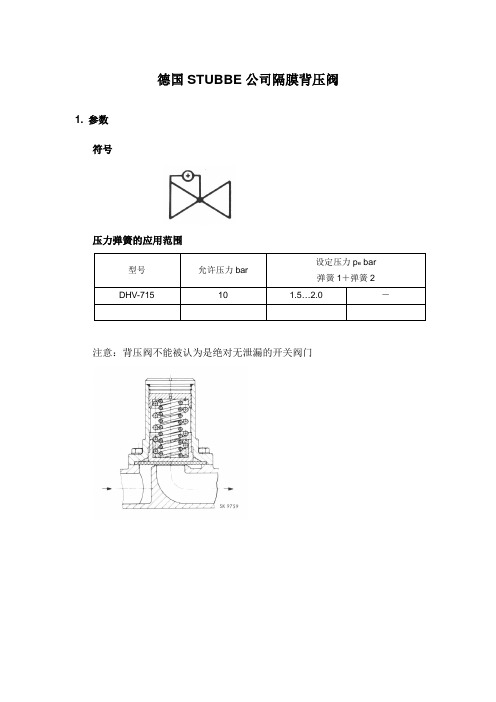
德国STUBBE公司隔膜背压阀1. 参数符号压力弹簧的应用范围注意:背压阀不能被认为是绝对无泄漏的开关阀门材质:PVC,PP,PVDF,PP-GFK,PVDF-GFK 按照参数表TA-015的可能连接。
尺寸g, i和p=拧紧固定阀门的螺栓到支架上2. 隔膜背压阀功能描述和操作手册2.1. 概述隔膜背压阀用于防止计量泵在不利计量的条件下的额外输送,阀门设定的压力能在泵进口管道和出流管道间产生必要的正压压差。
能用于没有固体的的自由流动的介质,特别用于其设计的用途,即只用于制造商指定的用途。
2.2. 工作模式隔膜背压阀在压力管道上安装,按下面情况工作:隔膜通过预先安装的弹簧关闭进口点,这样泵会对管道产生压力,预先设定的压力弹簧产生需要的正压压差。
由于泵会在压力管线上产生一定的压力,当压力到达隔膜背压阀设定压力时,隔膜打开,介质进入出流点,在压力下降到设定压力即关闭压力没有达到前进口点不会关闭。
一种阻尼液体(甘油)防止隔膜产生不希望的波动产生卡嗒卡嗒的噪声,这个水力阻尼系统只在隔膜安全阀安装在制定的位置是起作用。
2.3. 安装/装配隔膜背压阀安装在压力管线中,设计为在水平流向的流体中安装,盖必须垂直向上,隔膜安全阀必须按下面情况安装:没有来自供料管线或排放管线静态的、动态的或热的负载作用能传递到阀门。
流体方向由一个箭头标出。
(a)排放管出流管道的压力不能超过0.5bar2.4. 测试/鉴定隔膜安全阀在厂内进行测试并且已经设置到正确的操作压力,操作压力在铭牌上已标明,铭牌上还提供这些资料:型号,序号,材质,ND,NP(参见TA-017)在盖和帽之间有油漆作为密封。
2.5. 更换隔膜把整个阀门从管线上取下,遵守安全条例TA-002注意事项。
(a)拆卸拧开盖子用卡尺设置调节螺栓深度“┼”松开调节螺栓取下压力弹簧松开螺栓从阀体上取下阀帽隔膜可取出和更换(b)装配将隔膜插入阀帽内的凹进处用螺栓固定阀门到阀体上倒入缓冲液体直到弹簧的上沿插入弹簧拧调节螺栓到深度“┼”用螺栓固定盖到阀帽上2.6. 检查检查设定压力,比如用一个管道测试泵。
ABFV Series自动阀门说明书
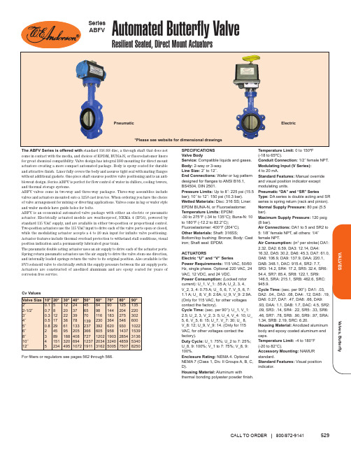
Compatible liquids and gases.Temperature Limit:(-18 to 65ºC).Conduit Connection: Modulating Input (V Series): 4 to 20 mA.(Common/NO/NC)NCFactory Mounted Solenoid Valve (Pneumatic Only)Explosion-Proof Electric Actuator (Electric Only) For Electric U and V actuators middle term, V_1, is the power supply required. Model Code 1 is for 120 VAC, 2 is for 220 VAC, 3 isValves, ButterflyVALVES5312-Way, Lug Style, EPDM LinerFor your convenience, sample model configurations are listed with the proper sized actuators. Models listed have cast iron body, 316 SS disc, and EPDM liner and O-rings. The 2-way models have a valve arrangement shown of normally closed, while the 3-way models have no valve arrangement code shown, please specify when ordering. All electric actuators shown are 115 VAC and NEMA 4. All pneumatic actuators are sized with an air supply pressure of 80 psi. Consult the factory for model number changes for electric actuator options of explosion-proof and other supply voltages.Size 2˝2-1/2˝3˝4˝5˝6˝8˝10˝12˝Double Acting PneumaticSpring Return Pneumatic Two Position Electric Modulating Electric Model Numbers shown are normally closed, change the model code at the end from “C” to “A” for normally open.2-Way, Wafer Style, EPDM LinerSize 2˝2-1/2˝3˝4˝5˝6˝8˝10˝12˝Double Acting PneumaticSpring Return Pneumatic Two Position Electric Modulating ElectricModel Numbers shown are normally closed, change the model code at the end from “C” to “A” for normally open.3-Way, Lug Style, EPDM LinerSize 2˝2-1/2˝3˝4˝5˝6˝8˝10˝12˝Double Acting PneumaticSpring Return Pneumatic Two Position Electric Modulating Electric*Complete model includes Valve Arrangement - see Model Chart on previous page.CALL TO ORDER | 800/872-9141OPTIONSOptional Electric Actuator Supply Voltages -Contact factory for model number changeSolenoid Valve - Add suffix -SV . . . . . . . . . . . . . . . . . . . . . . . . . . . .add $95.00b Price $251.00b 265.00b 288.00b 354.00b 521.00b 576.00b 759.00b 1215.00b 2176.00bPrice $354.00b 365.00b 395.00b 525.00b 802.00b 852.00b 981.00b 1874.00b 3158.00bPrice $846.00b 859.00b 1118.00b 1435.00b 1927.00b 1980.00b 2274.00b 3812.00b 4233.00bPrice $1951.00b 1974.00b 2228.00b 2530.00b 3017.00b 3099.00b 3429.00b 5034.00b 5404.00bPrice $243.00b 256.00b 289.00b 331.00b 497.00b 538.00b 792.00b 1199.00b 2207.00bPrice $343.00b 366.00b 412.00b 537.00b 791.00b 836.00b 964.00b 1850.00b 3005.00bPrice $815.00b 848.00b 1091.00b 1417.00b 1883.00b 1955.00b 2284.00b 3706.00b 4144.00bPrice $1900.00b 1942.00b 2152.00b 2466.00b 3065.00b 3111.00b 3358.00b 4785.00b 5376.00bPrice $1075.00b 1281.00b 1275.00b 1541.00b 2304.00b 2317.00b 3283.00b 5254.00b 7594.00b Price $1160.00b 1415.00b 1354.00b 1826.00b 2950.00b 2777.00b 3461.00b 6304.00b 9949.00b Price $1970.00b 2287.00b 2614.00b 2884.00b 3442.00b 3489.00b 4933.00b 6816.00b 9557.00b Price $3048.00b 3328.00b 3616.00b 3847.00b 4409.00b 4565.00b 5901.00b 7784.00b 10525.00bModelABFV202LTB331DA3C ABFV225LTB331DA3C ABFV203LTB331DA3C ABFV204LTB331DA3C ABFV205LTB331DA5C ABFV206LTB331DA5C ABFV208LTB331DA6C ABFV210LTB331DA8C ABFV212LTB331DAACModel ABFV202LTB331SR4C ABFV225LTB331SR4C ABFV203LTB331SR5C ABFV204LTB331SR6C ABFV205LTB331SR6C ABFV206LTB331SR8C ABFV208LTB331SR8C ABFV210LTB331SR9C ABFV212LTB331SRBC ModelABFV202LTB331U12C ABFV225LTB331U12C ABFV203LTB331U13C ABFV204LTB331U14C ABFV205LTB331U16C ABFV206LTB331U16C ABFV208LTB331U17C ABFV210LTB331U19C ABFV212LTB331U19CModel ABFV202LTB331V12C ABFV225LTB331V12C ABFV203LTB331V13C ABFV204LTB331V14C ABFV205LTB331V16C ABFV206LTB331V16C ABFV208LTB331V17C ABFV210LTB331V19C ABFV212LTB331V19C ModelABFV202WFB331DA3C ABFV225WFB331DA3C ABFV203WFB331DA3C ABFV204WFB331DA3C ABFV205WFB331DA5C ABFV206WFB331DA5C ABFV208WFB331DA6C ABFV210WFB331DA8C ABFV212WFB331DAACModel ABFV202WFB331SR4C ABFV225WFB331SR4C ABFV203WFB331SR5C ABFV204WFB331SR6C ABFV205WFB331SR6C ABFV206WFB331SR8C ABFV208WFB331SR8C ABFV210WFB331SR9C ABFV212WFB331SRBC ModelABFV202WFB331U12C ABFV225WFB331U12C ABFV203WFB331U13C ABFV204WFB331U14C ABFV205WFB331U16C ABFV206WFB331U16C ABFV208WFB331U17C ABFV210WFB331U19C ABFV212WFB331U19CModel ABFV202WFB331V12C ABFV225WFB331V12C ABFV203WFB331V13C ABFV204WFB331V14C ABFV205WFB331V16C ABFV206WFB331V16C ABFV208WFB331V17C ABFV210WFB331V19C ABFV212WFB331V19C Model*ABFV302LTB331DA3_ABFV325LTB331DA3_ABFV303LTB331DA4_ABFV304LTB331DA5_ABFV305LTB331DA6_ABFV306LTB331DA7_ABFV308LTB331DA9_ABFV310LTB331DAA_ABFV312LTB331DAB_Model*ABFV302LTB331SR5_ABFV325LTB331SR6_ABFV303LTB331SR6_ABFV304LTB331SR7_ABFV305LTB331SR9_ABFV306LTB331SR9_ABFV308LTB331SR9_ABFV310LTB331SRB_ABFV312LTB331SRC_Model*ABFV302LTB331U13_ABFV325LTB331U14_ABFV303LTB331U15_ABFV304LTB331U16_ABFV305LTB331U16_ABFV306LTB331U17_ABFV308LTB331U19_ABFV310LTB331U19_ABFV312LTB331U1A_Model*ABFV302LTB331V13_ABFV325LTB331V14_ABFV303LTB331V15_ABFV304LTB331V16_ABFV305LTB331V16_ABFV306LTB331V17_ABFV308LTB331V19_ABFV310LTB331V19_ABFV312LTB331V1A_b Items are subject to Schedule B discounts.。
贝利摩电子压力独立阀(P2100SU-182+LRX24-EP2)说明书

Electronic Pressure Independent Valve, 2-way,Internal thread, (EPIV)• Nominal voltage AC/DC 24 V • Control MFT/programmable• Communication via Belimo MP-Bus or conventional control• Conversion of active sensor signals and switching contactsTechnical dataElectrical dataNominal voltageAC/DC 24 V Nominal voltage frequency 50/60 Hz Power consumption in operation3.5 WData bus communicationNumber of nodes Max. 32 (without repeater)Functional dataValve size [mm]1" [25]Operating range Y 2...10 VOperating range Y note 4...20 mA w/ ZG-R01 (500 Ω, 1/4 W resistor)Input Impedance 100 kΩ (0.1 mA), 500 ΩOptions positioning signal VDC variable Position feedback U 2...10 V Position feedback U variable VDC variable Running Time (Motor)90 s Sound power level Motor 35 dB(A)Control accuracy ±5%Min. controllable flow 1% of V'nomFluidchilled or hot water, up to 60% glycol max (open loop/steam not allowed)Fluid Temp Range (water)14...250°F [-10...120°C]Close-off pressure ∆ps 200 psiDifferential Pressure Range 5...50 psi or 1...50 psi see flow reductions chart in tech docFlow characteristic equal percentage or linear Body Pressure Rating 360 psi GPM 18.2Servicing maintenance-free Manual overrideexternal push button Flow measurementMeasuring accuracy flow ±2%*Measurement Repeatability ±0.5% (Flow)Sensor TechnologyUltrasonic with glycol and temperature compensation Safety data Degree of protection IEC/EN IP54Degree of protection NEMA/UL NEMA 2Enclosure UL Enclosure Type 2Agency ListingcULus acc. to UL60730-1A/-2-14, CAN/CSA E60730-1:02, CE acc. to 2014/30/EU and2014/35/EU; Listed to UL 2043 - suitable for use in air plenums per Section 300.22(c) of the NEC and Section 602.2 of the IMC•••••Flow measurementSafety dataQuality Standard ISO 9001Ambient temperature -22...122°F [-30...50°C]Storage temperature -40...176°F [-40...80°C]Ambient humidityMax. 95% RH, non-condensing MaterialsValve bodyNickel-plated brass body Flow measuring pipe brass body nickel-plated Spindle stainless steel Spindle seal EPDM (lubricated)Characterized disc stainless steel TEFZEL®SeatPTFEPipe connection NPT female ends O-ring EPDM Ballstainless steelSafety notesThis device has been designed for use in stationary heating, ventilation and air-conditioning systems and must not be used outside the specified field of application, especially in aircraft or in any other airborne means of transport.Outdoor application: only possible in case that no (sea) water, snow, ice, insolation or aggressive gases interfere directly with the actuator and that is ensured that the ambient conditions remain at any time within the thresholds according to the data sheet.Only authorized specialists may carry out installation. All applicable legal or institutional installation regulations must be complied during installation.The device contains electrical and electronic components and must not be disposed of as household refuse. All locally valid regulations and requirements must be observed.WARNING: This product can expose you to lead which is known to the State of California to cause cancer and reproductive harm. For more information go to Product features*All flow tolerances are at 68°F [20°C] & water.AccessoriesElectrical accessoriesDescriptionType Replacement flow sensor for EPIV, Ultrasonic 1" 25M2425-EP Service Tool, with ZIP-USB function, for programmable andcommunicative Belimo actuators, VAV controller and HVAC performance devicesZTH USMechanical accessoriesDescriptionTypeWeather shield for Belimo Energy Valve™, 25...50, Ultrasonic models only ZS-EPIV-EV-50-SCNF Valve neck extension for ball valve DN 15 (50)ZR-EXT-01Electrical installationAC/DC 24 V, modulatingOperation on the MP-BusCable colors:1 = black 2 = red 3 = white5 = orange Cable colors:1 = black 2 = red 3 = white 5 = orangeControl with 4...20 mA via external resistorCaution:The operating range must be set to DC 2...10 V.The 500 Ohm resistor converts the 4...20 mA current signal to a voltage signal DC 2...10 V.Connection of active sensorsA) additional MP-Bus nodes (max. 8)• Supply AC/DC 24 V• Output signal DC 0...10 V (max. DC 0...32 V)• Resolution 30 mVFunctionsFunctions when operated on MP-Bus Connection on the MP-BusMP-Bus Network topologyA) additional MP-Bus nodes(max. 8)There are no restrictions for the network topology (star, ring, tree or mixed forms are permitted).Supply and communication in one and the same 3-wire cable • no shielding or twisting necessary• no terminating resistors requiredFunctions with specific parameters (Parametrisation necessary)Override control and limiting with AC 24 V with relay contactsOverride control and limiting with DC 24 V with relay contactsControl floating pointPosition control: 90° = 100sFlow control: Vmax = 100sDimensionsDimensional drawingsA B C D E F15.3" [388]9.1" [231] 5.8" [147] 5.0" [127] 2.0" [51] 2.0" [51]。
背压阀使用说明
背压阀使用说明背压阀是一种常用的控制阀,广泛应用于工业生产中。
本文将详细介绍背压阀的使用方法和注意事项,帮助读者正确使用背压阀,提高工作效率。
一、背压阀的基本原理背压阀是一种通过调节流体流量来控制压力的装置。
当流体通过背压阀时,背压阀会根据设定的压力值,调节阀门的开启程度,从而控制流体的流量和压力。
二、背压阀的安装步骤1. 首先,确定安装背压阀的位置,应选择在流体管道上游,以保证背压阀能够有效控制流体的流量和压力。
2. 清洁安装位置,确保没有杂质和污垢,以免影响背压阀的正常工作。
3. 将背压阀与管道连接,确保连接牢固,不漏水。
4. 根据实际需要,调节背压阀的开启程度,以适应不同的流量和压力要求。
三、背压阀的使用注意事项1. 在使用背压阀之前,应仔细阅读产品的使用说明书,并按照说明进行操作。
2. 在调节背压阀的开启程度时,应缓慢操作,避免突然调整导致压力波动。
3. 定期检查背压阀的工作状态,如发现异常情况应及时处理,以免影响生产效率。
4. 在更换背压阀时,应关闭流体管道,排空管道中的流体,确保安全操作。
5. 背压阀的使用环境应保持干燥清洁,避免灰尘和湿气对阀门造成损坏。
6. 长时间不使用背压阀时,应采取防护措施,如加盖防尘罩等,以延长使用寿命。
四、背压阀的常见故障及解决方法1. 背压阀漏水:检查阀门连接是否紧固,如有松动应及时拧紧;如阀门密封圈破损,应更换密封圈。
2. 背压阀无法调节压力:检查阀门内部是否有杂质堵塞,如有应清洁阀门内部;如阀门弹簧松动,应调节弹簧紧度。
3. 背压阀不灵敏:检查阀门内部是否有杂质影响阀门运动,如有应清洁阀门内部;如阀门密封圈老化,应更换密封圈。
总结:背压阀是一种重要的控制阀,正确使用背压阀可以提高工作效率,保障工业生产的顺利进行。
在使用背压阀时,应仔细遵循安装步骤和注意事项,及时处理常见故障,确保背压阀的正常工作。
希望本文的内容能为读者提供有用的信息和帮助。
阿尔法拉綽SB防压力阀门操作指南说明书
Company name, address and phone number
Hereby declare that Valve
Designation
SB Anti Vacuum Valve
Type
Serial number from AAB000000001 to AAC999999999 Serial number from 100700000001 to 100799999999
Conformity Assessment According to Directive 2014/68/EU Annex III Module D PED Quality Certificate No. QS-005-19 rev2
Notified Body Number: 1336 Inspecta Estonia OÜ Teaduspargi 8 12618 Tallinn ESTONIA The person authorised to compile the technical file is the signer of this document.
4
1 Declarations of Conformity
UK Declaration of Conformity
The Designated C, Albuen 31, DK-6000 Kolding, Denmark, +45 79 32 22 00
ZFY组合阀说明书(1)

ZFY(DN50、63、80)系列组合阀使用说明1.概述:本部套是油压装置的重要组成部分,是解决原油压装置中安全阀动作不稳定、噪声大及油泵起动冲击大,分立阀布局凌乱、渗漏点多等问题及产品的升级换代而设计生产的,较原来分立阀便于安装调整,杜绝减少了漏油点、提高了工作性能。
该阀将原来分立的单向阀、安全阀、旁通(卸荷)阀组合在一起并增设了低压起动阀,其中特别采用双油路液压时序控制、优化油路组合等技术并加设先导控制部分而形成了组合阀。
阀的四种功能可减少并组合成不同的功能满足用户要求,它适合于不含机械杂质的清洁油系统组合阀先导控制部分一般阀配置为机械型先导阀,而本阀旁通(卸荷)先导阀为电磁阀型。
较为先进的电磁阀先导控制方式使油压装置的油泵连续或其它工作方式的压差范围都在任意的可调整定范围(并使远控成为可能)用户更加方便。
另外,先导控制阀采用电磁阀,使油泵在起动时靠低压起动阀和电磁阀同时减载,而在停泵前用电磁先导阀使主阀打开卸荷,可达到空载停机,这样使阀具备了更完善的功能特别保护了油泵也保护了系统其它设备,并提供开创了更加合理的开停机方式。
它也为电站油压设备连续运行方式的稳定及设备可靠性和自动化水平的提高等均奠定了基础。
2.组合阀工作原理(见机械液压系统图)本组合阀是由两个主阀单元及三个先导控制阀组成。
构成了单向阀、安全阀、旁通(卸荷)阀和低压起动阀的功能。
在先导阀YV1、YV2、YV3控制下,主阀CV1完成开通和关闭的动作。
CV2是作为单向截止阀功能的主阀。
由于组合阀系统采用先导控制,因此当组合阀工作时无噪音、无震动、运行平稳。
液压系统图P2P1组合阀设有三个油口,组合阀压力油进口P1,组合阀出油口P2和组合阀回油口(1)T,P1口与油泵出口相连,出油口P2与压力油罐进口相连,回油口T与油箱内相通。
液压系统图中两个主阀CV及三个先导阀YV符号表示为:CV1—主阀(控制用主阀单元)CV2—单向阀主阀单元YV1—电磁旁通(卸荷)先导控制阀YV2—低压起动阀(卸载阀)YV3—安全先导控制阀2.1低压起动阀由于大功率螺杆泵及电动机所带负载大及惯量大,所以从启动到稳定状态需要一定的时间。
G-Series 背压阀Values 压力释放阀手册 美工制作 美国制造 电话:1-800-GRIF
G-SeriesInstruction ManualBack Pressure ValvesPressure Relief ValvesMade in the USA INSG-1003-R1012Call: 1 - 800 - GRIFFCO Website: www PLEASE READ THE FOLLOWING INFORMATION PRIOR TO INSTALLING GRIFFCO VALVE PRODUCTS. FAILURE TO FOLLOW THESE INSTRUCTIONS MAY RESULT IN INJURY1. Griffco Valve guarantees it’s products against defective material andworkmanship only. Griffco Valve assumes no responsibility for damage orinjuries resulting from improper installation, misapplication, or abuse of anyproduct.2. Griffco Valve assumes no responsibility for damage or injury resulting fromchemical incompatibility between its products and the process fluids to whichthey are subjected. Compatibility charts provided in Griffco Valve literature arebased on ambient temperatures of 70°F and are for reference only. Customersshould always test to determine application suitability.3. Consult Griffco Valve literature to determine operating pressure, temperature,and flow rate limitations before installing any Griffco Valve product. Themaximum recommended fluid velocity through this product is eight feet persecond. Higher flow rates can result in possible damage due to the waterhammer effect. Also note that maximum operating pressure is dependentupon material selection as well as operating temperature.4. This product is designed primarily for use with non-compressible liquids. Itshould NEVER be used or tested with compressible fluids such ascompressed air or nitrogen.5. Systems should always be depressurized and drained prior to installing ormaintaining Griffco Valve products.6. Temperature effect on piping systems should always be considered when thesystems are initially designed. Piping systems must be designed andsupported to prevent excess mechanical loading on Griffco Valve equipmentdue to system misalignment, weight, shock, vibration, and the effects ofthermal expansion and contraction.7. Because PVC and CPVC plastic products become brittle below 40°F, GriffcoValve recommends caution in their installation and use below thistemperature.8. Published operating torque requirements are based upon testing of new valvesusing clean water at 70°F. Valve torque is affected by many factors includingfluid chemistry, viscosity, flow rate, and temperature. These should beconsidered when sizing electric or pneumatic actuators.9. Due to differential thermal expansion rates between metal and plastic,transmittal of pipe vibration, and pipe loading forces DIRECT INSTALLATIONOF METAL PIPE INTO PLASTIC CONNECTIONS IS NOT RECOMMENDED.Wherever installation of plastic valves or strainers into metal piping systems isnecessary, it is recommended that at least 10 pipe diameter in length of plasticpipe be installed upstream and downstream of the plastic valve to compensatefor the factors mentioned above.TABLE OF CONTENTS Limited Warranty:Safety Precautions:Introduction:Description:Product Coding:Installation:Unpacking:Installation:Operation:Start-upSet Pressure Adjustment Specifications:Dimensions:Maintenance:Routine Maintenance:Parts List:LIMITED WARRANTYGriffco Valve Inc. (“GVI”) warrants that its products shall be free from defects in material and workmanship for a period of one year under normal use or eighteen (18) months from date of shipment, which first occurs. Defects caused by shipment, improper installation, negligence or misuse by parties other than GVI are not covered by this limited warranty. This limited warranty is extended only to the original purchaser from GVI.The purchaser must promptly notify GVI of any claimed defect. Products may only be returned to GVI upon purchaser’s receipt of written consent from GVI. Products are to be returned to GVI with freight prepaid. If GVI’s inspection shows the products to be defective, GVI’s liability in respect of defective products shall be to repair or replace such item(s) in its discretion.EXCEPT FOR THE EXPRESS LIMITED WARRANTY SET FORTH HERE, NO OTHER IMPLIED WARRANTIES OF ANY KIND, INCLUDING BUT NOT LIMITED TO IMPLIED WARRANTIES OF MERCHANTABILITY OR FITNESS FOR A PARTICULAR PURPOSE OR USE, ARE HEREBY DISCLAIMED. GVI SHALL NOT BE LIABLE FOR ANY DIRECT, INDIRECT, SPECIAL, INCIDENTAL OR CONSEQUENTIAL DAMAGES OR LOSSES.GVI’S MAXIMUM LIABILITY SHALL NOT IN ANY EVENT EXCEED THE CONTRACT PRICE FOR THE PRODUCT.SAFETY PRECAUTIONSAlways follow the safety instruction below:Wear protective clothing and glasses when working with or near chemicals.Refer to the MSDS for all chemicals used.Use on Genuine Griffco parts. Use of other parts may result in damage to equipment or injury andinvalidate warranty.Flush all components that are in contact withchemicals prior to servicing.Secure all chemicals and equipment making them inaccessible to children and pets.Dispose all chemicals and waste according to all local, state and federal regulations.Stop the flow of chemical through the system prior to working on the valve.Do Not exceed the maximum operating pressure.GRIFFCO diaphragm back pressure valves are used to enhance the performance of chemical feed pumps and systems by providing a constant discharge head pressure. These valves also function as an anti-siphon valve. The diaphragm is held against the seat by the internal spring. Back pressure is adjustable from 10 - 150 psi via the adjustment screw. When the inlet pressure exceeds the preset pressure the diaphragm lifts off the seat and the chemical flows to the injection point. After each discharge stroke of the pump, as the pressure drops, the diaphragm reseats itself.GRIFFCO diaphragm pressure relief valves are designed to protect chemical feed pumps and systems from overpressure caused by defective equipment or blockages in the chemical line. The 3 port design allows chemical to flow through the valve via an internal chamber. When the pressure in the chemical line exceeds the preset pressure of the valve the diaphragm lifts off the seat and the chemical then flows out the bottom port back to the chemical tank. Relief pressure is adjustable via the adjustment screw in the top of the valve.Product Coding for Valves:BPG/PRG □□□□□□1 2 3 41 = Size2 = Material3 = Spring4 = Options050 - 1/2” P - PVC 1 - 0 - 50 psi V - Viton Diaphragm075 - 3/4” CP - CPVC 2 - 10 - 250 psi S - Socket Connection100 - 1” PP - Polypro F - Flange Connection155 - 1 1/2” T - PTFE U - Union Connection200 - 2” K - PVDF B - BSP Connections300 - 3” H - Halar OSS - 316 SS Top400 - 4” S - 316 SS MSS - 50 - 350 psiA - Alloy 20 AR - Priming ValveC - Hastalloy C 90 - 90° ConfigurationUnpacking:Units are shipped FOB factory and the title passes to the customer when the carrier signs for the receipt of the unit. In the event damages occur during shipment, it is the responsibility of the customer to notify the carrier immediately and to file a damage claim.Check all orders for completeness against the packing list. Notify Griffco Valve Inc. immediately if any deficiencies are found.The carton should contain:1 Backpressure valve of Pressure Relief valve1 Instruction ManualAccessories as orderedInstallation:As a general rule, installation should follow the layout as outline in the “TYPICAL INSTALLATION” drawing. Back Pressure Valve:Generally, the back pressure valve can be installed anywhere in the discharge line, provided there is some downstream pressure at the dosage point. If there is no downstream pressure the back pressure valve should be installed at the dosage point to prevent siphoning and drainage of the chemical line. The valve can be installed either vertically or horizontally. The flow must be across the valve in the direction of the arrow. All GRIFFCO valves are factory set at 50 psi, unlessotherwise specified. Field adjustment is possible with the adjustment screw.Back pressure valve performance will be enhanced with the installation of a pulsation dampener to smooth out the discharge / suction cycles of the pump. Thus, the diaphragm is free to float inside the valve chamber, minimizing the wear on the stress points of the diaphragm. Pulsation dampeners will also reduce the pressure drop across the valve by reducing peak flows. Backpressure valves should be installed downstream of the dampener. For most applications diaphragm type dampeners are required. Generally speaking 5 to 10% dampening is sufficient. Consult with your pump manufacturer to get his recommendations. Pressure Relief Valve:3 Port Valves:Installation should be made as close to the chemical pump discharge valve as possible, without any equipment, especially shut-off valves, between the valve and the pump. Direction of flow must be across the valve; however the side of entry is not important. The valve can be installed either vertically or horizontally. The relief port is on the bottom of the valve.2 Port 180° Valves:Installation of a tee should be made as close to the chemical pump discharge valve as possible, without any equipment, especially shut-off valves, between the valve and the pump. The flow can travel at 90° or 180° through the tee, with the relief valve connected to the 3rd port of the tee. Direction of relief flow must be in the direction of the arrow on the valve.2 Port 90° Valves:Installation of a tee should be made as close to the chemical pump discharge valve as possible, without any equipment, especially shut-off valves, between the valve and the pump. The flow can travel at 90° or 180° through the tee, with the relief valve connected to the 3rd port of the tee. Direction of relief flow must be in the side of the valve with the relief port being on the bottom.The optimum installation for any relief valve is to vent the relief port back to the chemical tank, or directly to a containment area. However if this is not possible, the relief port can be piped back into the suction side of the pump. This will apply the suction head to the relief port. To compensate, divide the NPSH by 4 and add this pressure to the relief valve setting. Do not put a shut off valve in the relief line.All GRIFFCO valves are factory set at 50 psi, however field adjustment is possible with the adjustment screw.Important Precautions:Do not over tighten the connection piping.It is not recommended threading metal pipe or pipe fittings into plastic valves.Care should be taken when applying thread sealant to pipe threads not to use excessive amounts as the sealantcould break free and get lodged between the valve seatand the diaphragm causing the valve to weep.Check to ensure that the valve bolts are tight.Do not bottom out the adjustment screw.OPERATIONStart-up:Before starting the chemical feed system make sure the backpressure and safety valves are installed correctly and the proper pressures are set for the application. The valves are factory set at 50 psi unless otherwise specified. Valves can be field adjusted.Adjusting Set Pressure:The set pressure of the valves can be adjusted to any pressure value between the maximum and minimum value as stated on the valve ID tag. This is done via the adjustment screw located under the black cap on the top of the valve. To increase the pressure, turn the screw clockwise. This should be done with the pump operating and a pressure gauge installed between the pump and the back pressure valve. If no gauge is installed the pressure can be estimated to change approximately 8 psi per revolution with the standard 150 psi spring.Caution:Pressure setting changes should be made only after careful consideration of the effect of the change on the entire hydraulic system, including the chemical feed pump.Never attempt to adjust the valve outside the pressure limit as improper operation and/or damage to the valve and/or system components may occur.MAINTENANCEGeneral:Griffco valves were designed with a minimum amount of maintenance required to keep the valves in operation. However, periodic replacement of the diaphragm is required. The Griffco design permits routine inspection and repair without removing the valve from the pump line.Caution:Ensure that the chemical feed system is not under pressure and that the chemical lines have been flushed with water before starting disassembly.Unscrew the pressure adjustment screw to remove the pressure from the diaphragm. Remove the 4 bolts and lift off the valve top.After the diaphragm and the valve seat have been inspected and replaced if necessary, (White PTFE side down), check the adjustment spring. Make sure there is no rust or corrosion. Place the support disc the spring onto the valve body and slide the top back over the four bolts.Tighten the 4 bolts, and then replace the adjustment screw. Turn the adjustment screw clockwise to approximately the same position as it was prior to disassembly. If an exact pressure setting is required or a different pressure is desired a pressure gauge should be used to verify the setting. Turning the adjustment screw clockwise will increase pressure.Use only genuine Griffco Valve parts in your Griffco Valves.SPARE PARTSCOMMON VALVE PARTS:ITEM DESCRIPTION PART #1 1/4 - 20 X2 3/4" Bolt - 1/2 - 1" Plastic Valves5/16 - 18 X 1 1/2” Bolt - 1 1/2” - 2” Metal Valves1/4 - 20 X 4.5” - 1 1/2” Plastic Valves (5” OD Body)1/4 - 20 X 5” Bolt - 1 1/2” (OBS 4.5” OD); & 2” Plastic Valves (5” OD)1/4 - 20 X 1 1/4" Bolt - 1/2 - 1" Metal Valves PV-00101 PV-00102 PV-00104 PV-00105 PV-001082 1/4 - 20 Cap hex nut PV-002023 1/4 Flat Washer (Required with 316 SS Top)5/16 Flat washer (Required with 316 SS Top) PV-00302 PV-003034 1/2" - 1" Valve Top – Noryl. Black1/2" - 1" Valve Top – Noryl, Orange1/2" - 1" Valve Top – Noryl, Yellow1/2" - 1" Valve Top – Noryl, Green1/2" - 1" Valve Top – Noryl, Grey1/2" - 1" Valve Top - 316 SS1 1/2” Valve Top; 4 ½” Valves, PVC1 1/2” Valve Top; 4 ½” Valves. 316 SS2” Valve Top; 5” Valves, Noryl2” Valve Top; 5” Valves. 316 SS PV-004451 PV-004452 PV-004053 PV-004054 PV-004450 PV-00407 PV-00411 PV-00413 PV-00414 PV-004166 Pressure Spring - 1/2" - 1" Valve; 150 psiPressure Spring - 1/2" - 1" Valve; 50 psiPressure Spring - 1/2" - 1" Valve; 250 psiPressure Spring - 1/2" - 1" Valve; 350 psiPressure Spring - 1/2" - 1" Valve; 100 psi, 316 SSPressure Spring - 1 1/2” - 2” Valve; 150 psiPressure Spring - 1 1/2” - 2” Valve; 50 psi PV-00602 PV-006021 PV-006023 PV-006122 PV-00602S PV-00603 PV0060337 Support Disc - 1/2 - 1" Valve, PVCSupport Disc - 1/2 - 1" Valve, 316 SSSupport Disc - 11/2” - 2” Valve, PVCSupport Disc - 11/2” - 2” Valve, 316 SS PV-00705 PV-00706 PV-00708 PV-007098 Diaphragm - 1/2" - 1" Valve - PTFE / EPDMDiaphragm - 1/2” - 1” Valve – VitonDiaphragm - 1/2" - 1" Valve - PTFE / Viton (High Temperature)Diaphragm - 1 1/2” Valve - PTFE / EPDM (OBS 4.5” OD Body)Diaphragm - 1 1/2” Valve – Viton (OBS 4.5” OD Body)Diaphragm - 1 1/2” Valve – PTFE/Viton (OBS 4.5” OD Body)Diaphragm - 1 1/2” - 2” Valve – PTFE/EPDM (5” OD Body)Diaphragm - 1 1/2” - 2” Valve – Viton ( 5” OD Body) PV-00810 PV-00812 PV-00813 PV-00820 PV-00821 PV-00822 PV-00830 PV-008319 Adjustment Screw - 1/2” - 1” Valve PET (white)Adjustment Screw - 1/2” - 1” Valve Coated SteelAdjustment Screw - 1 1/2” - 2” Valve PVCAdjustment Screw - 1 1/2” - 2” Valve Coated Steel PV-00906 PV-00903 PV-00926 PV-0092110 Protective Vinyl Cap- 1/4” – 1” ValvesProtective Vinyl Cap- 1 1/2" – 2” Valves PV-01001 PV-01002BACKPRESSURE VALVE PARTSITEM DESCRIPTION PART #5 1/2" Valve Body PVC1/2" Valve Body PP1/2" Valve Body PTFE1/2" Valve Body PVDF1/2" Valve Body 316 SS1/2" Valve Body Alloy 201/2" Valve Body Hast C1/2" Valve Body CPVC3/4" Valve Body PVC3/4" Valve Body PP3/4" Valve Body PTFE3/4" Valve Body PVDF3/4" Valve Body 316 SS3/4" Valve Body Alloy 203/4" Valve Body Hast C3/4" Valve Body CPVC1" Valve Body PVC1" Valve Body PP1" Valve Body PTFE1" Valve Body PVDF1" Valve Body 316 SS1" Valve Body Alloy 201" Valve Body Hast C1" Valve Body CPVC1 1/2" Valve Body PVC (5” OD)1 1/2" Valve Body PP (5” OD)1 1/2" Valve Body PTFE (5” OD)1 1/2" Valve Body PVDF (5” OD)1 1/2" Valve Body 316 SS (5” OD)1 1/2" Valve Body Alloy 20 (5” OD)1 1/2" Valve Body Hast C (5” OD)1 1/2" Valve Body CPVC (5” OD)2" Valve Body PVC2" Valve Body PP2" Valve Body PTFE2" Valve Body PVDF2" Valve Body 316 SS2" Valve Body Alloy 202" Valve Body Hast C2" Valve Body CPVC BPV-00511 BPV-00512 BPV-00513 BPV-00514 BPV-00515 BPV-00516 BPV-00517 BPV-00518 BPV-00521 BPV-00522 BPV-00523 BPV-00524 BPV-00525 BPV-00526 BPV-00527 BPV-00528 BPV-00531 BPV-00532 BPV-00533 BPV-00534 BPV-00535 BPV-00536 BPV-00537 BPV-00538 BPV-50541 BPV-50542 BPV-50543 BPV-50544 BPV-50545 BPV-50546 BPV-50547 BPV-50548 BPV-00551 BPV-00552 BPV-00553 BPV-00554 BPV-00555 BPV-00556 BPV-00557 BPV-00558PRESSURE RELIEF VALVE PARTSITEM DESCRIPTION PART #5 1/2" Valve Body PVC1/2" Valve Body PP1/2" Valve Body PTFE1/2" Valve Body PVDF1/2" Valve Body 316 SS1/2" Valve Body Alloy 201/2" Valve Body Hast C1/2" Valve Body CPVC3/4" Valve Body PVC3/4" Valve Body PP3/4" Valve Body PTFE3/4" Valve Body PVDF3/4" Valve Body 316 SS3/4" Valve Body Alloy 203/4" Valve Body Hast C3/4" Valve Body CPVC1" Valve Body PVC1" Valve Body PP1" Valve Body PTFE1" Valve Body PVDF1" Valve Body 316 SS1" Valve Body Alloy 201" Valve Body Hast C1" Valve Body CPVC1 1/2" Valve Body PVC (5” OD)1 1/2" Valve Body PP (5” OD)1 1/2" Valve Body PTFE (5” OD)1 1/2" Valve Body PVDF (5” OD)1 1/2" Valve Body 316 SS (5” OD)1 1/2" Valve Body Alloy 20 (5” OD)1 1/2" Valve Body Hast C (5” OD)1 1/2" Valve Body CPVC (5” OD)2" Valve Body PVC2" Valve Body PP2" Valve Body PTFE2" Valve Body PVDF2" Valve Body 316 SS2" Valve Body Alloy 202" Valve Body Hast C2" Valve Body CPVC PRV-00511 PRV-00512 PRV-00513 PRV-00514 PRV-00515 PRV-00516 PRV-00517 PRV-00518 PRV-00521 PRV-00522 PRV-00523 PRV-00524 PRV-00525 PRV-00526 PRV-00527 PRV-00528 PRV-00531 PRV-00532 PRV-00533 PRV-00534 PRV-00535 PRV-00536 PRV-00537 PRV-00538 PRV-50541 PRV-50542 PRV-50543 PRV-50544 PRV-50545 PRV-50546 PRV-50547 PRV-50548 PRV-00551 PRV-00552 PRV-00553 PRV-00554 PRV-00555 PRV-00556 PRV-00557 PRV-00558SPECIFICATIONSG-Series Sizes: 1/2”, 3/4”, 1”, 1 1/2”, 2”, 3”, 4” Flow Rates @ 150 psiSize Pulsating Continuous1/2” 3/4” 1”1 1/2” 2” 3” 4” 300 USgph300 USgph500 USgph1200 USgph2350 USgph5200 USgph5200 USgph21 USgpm21 USgpm26 USgpm63 USgpm120 USgpm270 USgpm270 USgpmMax Temp: (°F) PVC: 140° ; CPVC & PP: 195°;PTFE, PVDF & Metal: 300°, (Peak 390°)Max Operating Pressure(psi) @ 70°F Plastic/Noryl: 375 psi Metal/Metal: 2000 psiPressure Adjustment Standard: 10 - 150 psi; Optional: 0 – 50psi, 10 – 250 psi, 50 - 350 psi*Note: Size 1 1/2” and Larger BPG valves10 – 250 psi Max range ONLY.Materials ofConstruction:Diaphragm PTFE / EPDM,Optional: Viton, Hypalon, & PTFE / Viton Valve Body PVC, CPVC, PP, PTFE, PVDF, Halar,316 SS, A 20, Hast. CDimensions:DIMENSIONS: BPG-SERIES All M aterialsA(in)B(in)C(in)Size 1/2"3/4"1" 5.5605.5605.860 3.5003.5003.500 1.1251.1251.2504.9008.350 1.8254.9008.900 2.1502"1 12"NOTESGriffco Valve Inc.6010 N. Bailey Ave.Ste 1BAmherst, NY 14226USAPhone: 1 716-835-08911 800-GRIFFCOFax: 1 716-835-0893E-Mail: ********************** Website: INSG-1003-R1012 Revision Date 10/12/15。
304泄压和背压阀说明书
304泄压和背压阀说明书一、产品概述304泄压和背压阀是一种用于控制系统中液体或气体流动的装置,其工作原理是通过调节活塞或膜片的位置来控制流体的压力,从而实现泄压或背压的功能。
本产品适用于各种工业领域,广泛应用于化工、石油、制药等行业。
二、产品特点1.结构简单:304泄压和背压阀采用了简洁的结构设计,由少量的零部件组成,操作方便,使用寿命长。
2.调节范围广:该阀型可根据实际需求调节压力范围,满足不同工作条件下的需求。
3.密封性能好:采用高质量的密封材料,确保了产品的密封性能,防止泄漏。
4.耐腐蚀性强:本产品采用优质不锈钢304材质制造,具有良好的耐腐蚀性,可在各种腐蚀介质中使用。
5.安全可靠:304泄压和背压阀在使用过程中稳定可靠,能够保护系统免受过高压力或负压的影响。
三、产品使用注意事项1.在安装之前,请确保产品和管道之间的连接是稳固可靠的,并检查是否有漏气或漏液的现象。
2.使用前,请仔细阅读产品说明书,了解产品的工作原理和使用方法。
3.根据实际需求,正确调节产品的工作压力范围,不得超过产品规定的最大工作压力。
4.定期检查产品的密封性能,如有发现损坏或老化现象,请及时更换密封件。
5.使用过程中,请避免在阀门关闭状态下长时间施加压力,以免损坏阀门。
6.如需更换零件或进行维修,请选择正规厂家或经销商提供的原装零件,以确保产品安全可靠。
四、产品维护保养1.定期清洁产品表面,保持产品的外观清洁,并及时清除物料残留。
2.定期检查阀门的工作状态,如发现异常情况,请及时进行维修或更换。
3.定期检查阀门的连接部位是否有松动或渗漏的现象,如有发现,请及时处理。
4.在长时间不使用的情况下,应将产品存放在干燥通风的场所,以避免产品受潮生锈。
五、技术参数1.产品材质:不锈钢3042.工作压力范围:0-2MPa3.适用介质:液体、气体4.安装方式:垂直安装5.适用温度范围:-20℃~200℃六、产品安装示意图(图示产品的外观和安装方向,详细说明各个部件的安装位置和连接方式)七、售后服务本公司承诺提供优质的售后服务,对于产品出现的质量问题,提供免费维修或更换服务。
直通式背压阀操作方法
直通式背压阀操作方法直通式背压阀是一种常见的阀门,常用于控制管道系统中的流体压力。
它通常由阀体、活塞、弹簧和密封件组成,其操作方法如下:1. 阀门安装与调整(1) 在安装阀门之前,需要对管道进行清洁和维修,确保流体能够顺利通过。
(2) 根据管道的直径和操作压力选择合适的规格和型号的直通式背压阀,并将其安装于管道上。
确保阀门与管道之间的连接牢固,不会出现漏水或漏气的情况。
(3) 调整阀门的开启和关闭压力,以适应不同的工况要求。
调整方法通常是通过松开或紧固阀头上的螺母来改变弹簧的压紧程度。
增加弹簧的压力会增加阀门的关闭压力,反之亦然。
2. 阀门的开启与关闭(1) 当管道中的压力超过设定的背压阀开启压力时,阀门会自动打开,允许流体通过。
当流体的压力降低到设定的关闭压力以下时,阀门会自动关闭,阻止流体的通过。
(2) 当需要手动控制阀门的开启或关闭时,可以轻轻转动阀头上的螺杆,以改变阀门的打开程度。
对于部分背压阀,还可以通过旋转阀盖上的螺纹杆来控制阀门的开闭。
3. 液体流量调节直通式背压阀可以根据不同的流量需求进行调节。
可以通过改变阀门打开的程度来改变流体通过阀门的速度。
一般来说,打开阀门越多,流体通过的速度越快。
4. 使用注意事项(1) 使用直通式背压阀时,应确保流体的压力不会超过阀门的承载范围。
如果压力过高,可能导致阀门损坏或无法正常关闭。
(2) 定期检查直通式背压阀的工作状况,并进行维护和清洁。
保持阀门及其周围区域的清洁,可以延长阀门的使用寿命。
(3) 如果发现阀门无法正常关闭或打开,或者有异样噪音,应立即停止使用,并进行检修。
避免因阀门故障导致系统失效或设备损坏。
总之,直通式背压阀是一种用于控制流体压力的重要装置。
通过按照正确的安装方法和操作步骤来使用和维护阀门,可以确保背压阀的正常运行,并提高管道系统的安全性和可靠性。
背压阀工作原理
背压阀工作原理
背压阀是一种常见的流体控制阀门,用于调节流体的压力和流量。
它的工作原理基于阀芯的位置和流体压力之间的关系。
背压阀通常由阀体、阀盖、阀芯和弹簧组成。
阀芯通过弹簧和流体压力的作用来实现对流体的调节。
当流体进入背压阀时,流体的压力作用在阀芯上。
阀芯的位置取决于流体压力和弹簧的力量之间的平衡。
当流体压力较低时,阀芯会被压力推向阀座,关闭阀门,阻挠流体通过。
这种情况下,背压阀起到了防止流体倒流的作用,保持了系统的稳定性。
当流体压力增加时,压力会克服弹簧的力量,将阀芯推开,打开阀门,允许流体通过。
阀芯的位置会随着流体压力的变化而调整,以保持流体的稳定流量。
背压阀的工作原理可以通过一个简单的公式来描述:流体压力 = 弹簧力 + 阀芯位置造成的压力损失。
通过调整弹簧的强度和阀芯的设计,可以实现对流体压力和流量的精确控制。
背压阀在许多工业应用中起到了重要的作用。
例如,在供水系统中,背压阀可以防止水流倒流,保护水泵和其他设备的正常运行。
在化工过程中,背压阀可以调节流体的压力,确保系统的稳定性和安全性。
总结起来,背压阀是一种通过调节阀芯的位置和流体压力之间的平衡来控制流体压力和流量的阀门。
它的工作原理简单而有效,可以在各种工业应用中实现对流体的精确控制。
forge泄压阀说明书
Forge Motorsport 2.0T FSI Replacement Bypass Valve KitPlease thoroughly read through and familiarize yourself with these instructions prior to beginning the installation process of any component. Please also ensure that the vehicle and engine have cooled down sufficiently to avoid risking skin burns or other injury.Tools Required:- Vehicle jack and jack stands or access to a vehicle lift- 5mm Allen wrench or Allen socket with extension- 3mm Allen wrench- 1/8 Inch Allen Wrench- Razor blade or Xacto knife to cut vacuum line- Blue colored medium strength semi-permanent Loc-Tite thread lockerBegin by safely lifting the vehicle and then locating the turbo and the OEM electronically controlled bypass valve/solenoid, which will be bolted to the compressor cover of the turbo.- On the MK5 VW GTI and Jetta GLI, the B6 Passat, and the 8P Audi A3, the OEM valve will be bolted to the turbo located on the lower passenger side of the rear of the motor.- On the Golf ED30 and R, Leon Cupra, Scirocco R and Audi S3 the valve is located at the top of the engine bay at the front directly behind the radiator- On the B7 Audi A4, the OEM valve will be bolted to the turbo located on the passenger side of the motor towards the front underside of the carOnce located, disconnect the electrical connector/plug for the valve and you can now use your5mm Allen wrench or socket to remove the three 5mm Allen bolts which secure the valve to the turbo. You must be sure to save the OEM valve bolts as they will be reused later.With the OEM valve removed from the turbo, you can now temporarily install the Forge replacement valve reusing the OEM bolts with them only hand-tightened. This initial installation is only temporary so as to find an appropriate mounting location for the solenoid and to find the appropriate lengths for the vacuum lines you will use on your car.First, attach the solenoid to your choice of the supplied brackets using the two supplied 5mm Allen bolts. The solenoid can be mounted anywhere in the engine bay within reach of the solenoid wiring.For the purpose of generating these instructions, we will mount the solenoid bracket using one of the bolt holes for the new Forge valve as shown below. You do not have to install the solenoid bracket in this manner on your application if you would prefer a different location.With the new Forge valve loosely mounted to the turbo, and a location selected for the solenoid and it loosely mounted as well, measure to find appropriate lengths for the vacuum hose connections between the valve and the solenoid.Please use the plumbing diagram below for the appropriate locations to connect the vacuum lines. As stipulated in the plumbing diagram, the plumbing MUST be as shown or the valve may fail to operate properly or possibly at all.Once you have determined the length of vacuum line you will need between each connection of the valve and the res pective connection on the solenoid, you can cut the appropriate lengths of line from the included s pool. The lengths you cut and use will be based on where in the engine bay you have chosen to mount the solenoid.You can now remove everything from the car to secure the lines between the valve and solenoid as shown above.With the valve and solenoid plumbed together and the lines secured with the included zip ties, you can now permanently mount the valve and solenoid bracket.Use your 5mm Allen wrench to bolt the new Forge valve to the turbo from where the OEM valve was removed, again, reusing the OEM valve bolts.Securely clip the supplied wiring harness to the solenoid (it is a tight fit) before you mount the solenoid in the engine bayWith the valve securely mounted to the turbo and the solenoid bracket also secured at your desired location within the engine bay, you can reconnect the OEM wiring harness plug to the connection on the end of the Forge wiring harness.We will now move on to the vacuum tap piece which will need to be connected to the intake manifold. The vacuum tap has 3 tap provisions and is supplied with multiple vacuum nipples and blanking plugs for you to select the number of provisions you will need on your application.- One nipple must be used at a minimum for valve operation. (largest port nipple only)- A second nipple can be used for a boost gauge tap. (s mallest port nipple only)- A third provision is available and can be used for whatever it may be needed for on your application.- All unused port provisions must be plugged with the supplied port plugs. (3mm Allen)It is highly recommended that all vacuum nipples and port plugs are secured with blue colored, medium strength, semi-permanent Loc-Tite thread locker. If not used, the vacuum nipples and port plugs may back out, becoming lost and/or causing a vacuum/boost leak.To install the vacuum tap, you will need to unclip the PCV hose connection on the intake manifold. This can be found up and to the right of the throttle body while looking at the manifold. Pinch down on the two ribbed sections releasing the clips and pull the hose out of the manifold barb.Next, you will slide the manifold tap over the barb until the edge of the lip can no longer be seen through the grooves in the tap. Once the lip is no longer visible, insert the black plastic C-clip to secure the tap in place. The o-ring seals are very tight and secure, so this may take a small bit of effort.Once the manifold tap is held securely in place with the plastic C-clip, reattach the PCV hose to the barb at the end of the tap.If you are using some sort of PCV “fix” or “bypass”, h owever, you will need to reconnect whatever components are supplied with that product. The barb on the end of our manifold tap is the same size and shape as the OEM manifold barb, so any hoses or caps that connect to the manifold barb will connect to the barb on our tap as well.From the appropriate nipple on the manifold tap (largest port), run a length of vacuum tubing along the top of the motor, around the passenger side, following the fuel rail and fuel lines, down to the remaining linear port on the solenoid you mounted previously. (See plumbing diagram) Secure both ends of this line using two of the included zip ties. If any s pare zip ties are available, use them to secure this vacuum line to the fuel rail and/or fuel lines.Your valve installation is now complete, and you can now enjoy all of the benefits that a more reliable and performance orientated bypass valve has to offer. You should notice slightly quicker spool, less tapering, more responsive mid-range, and overall better valve and boost response.打造赛车 2.0T FSI 置换旁路阀工具包请彻底阅读并熟悉这些指令之前,在开始任何组件的安装过程。
背压阀工作原理

背压阀工作原理背压阀是一种用于控制流体压力的装置,它能够在管道中形成一定的阻力,以调节流体的流量和压力。
背压阀通常由阀体、阀座、阀瓣、弹簧和调节装置等组成。
下面将详细介绍背压阀的工作原理。
1. 工作原理概述背压阀的工作原理基于阀瓣与阀座之间的压力差。
当流体从管道中通过背压阀时,阀瓣受到流体压力的作用,与阀座之间形成一定的阻力。
当流体压力超过背压阀设定的压力时,阀瓣会打开,允许流体通过;当流体压力低于设定压力时,阀瓣会关闭,形成阻塞,从而调节流体的压力。
2. 结构组成背压阀的主要组成部份包括阀体、阀座、阀瓣、弹簧和调节装置等。
- 阀体:背压阀的阀体通常由金属材料制成,具有良好的耐压性能和密封性能。
- 阀座:阀座是阀瓣与阀体之间的接触面,通常采用耐磨损、耐腐蚀的材料制成,以确保密封性能和使用寿命。
- 阀瓣:阀瓣是背压阀的关键部件,它的开合状态决定了流体的通过与阻塞。
阀瓣通常由金属或者弹性材料制成,具有良好的密封性能和耐磨损性能。
- 弹簧:弹簧是背压阀的负荷调节装置,通过调节弹簧的压力,可以改变背压阀的工作压力范围。
- 调节装置:背压阀通常配备有调节装置,用于调节阀瓣的开合程度,从而控制流体的压力。
3. 工作过程背压阀的工作过程可以分为开启和关闭两个阶段。
- 开启阶段:当管道中的流体压力超过背压阀设定的压力时,阀瓣受到压力的作用,逐渐打开。
此时,流体可以通过阀瓣与阀座之间的间隙,流动到下游管道中,从而降低管道中的压力。
- 关闭阶段:当流体压力降低到背压阀设定的压力以下时,弹簧的作用力将阀瓣推向阀座,形成阻塞。
此时,阀瓣与阀座之间的间隙被封闭,阻挠了流体的进一步流动,从而增加管道中的压力。
4. 工作特点背压阀具有以下几个工作特点:- 调节流体压力:背压阀通过调节阀瓣的开启程度,可以控制流体的压力,从而满足管道系统的要求。
- 稳定性好:背压阀采用弹簧负荷调节装置,可以在一定范围内稳定控制流体压力,具有较好的稳定性。
- 1、下载文档前请自行甄别文档内容的完整性,平台不提供额外的编辑、内容补充、找答案等附加服务。
- 2、"仅部分预览"的文档,不可在线预览部分如存在完整性等问题,可反馈申请退款(可完整预览的文档不适用该条件!)。
- 3、如文档侵犯您的权益,请联系客服反馈,我们会尽快为您处理(人工客服工作时间:9:00-18:30)。
背压阀
背压阀的名词来源于Back Pressure Valve。
它代表的意思是说由于阀的功能而形成一定的压力,压力一般可以调节。
可用于控制空气、水、蒸汽、各种腐蚀性介质、泥浆、油品、液态金属和放射性介质等各种类型流体的流动。
启闭件是一个圆盘形的阀板,在阀体内绕其自身的轴线旋转,从而达到启闭或调节的目的。
在管道上主要起切断和节流作用。
最常用的系统有,流体计量投加系统、液压控制系统、化学反应条件、物态临界状态控制等。
基本可以分为调节和过流两部分。
一、概述
BYF法兰背压阀功能:此背压阀是温州闽嘉阀门有限公司引进国外先进技术,加上自主刻苦钻研的研究成果,本产品集安全阀\止回阀\调节阀\水锤消除器的功能于一体,在管道中一般安装起减压稳压,防止介质虹吸倒流,调节流量,保护计量泵,减少水锤的作用,一般配套脉动阻尼器。
背压阀通过内置弹簧的弹力来实现动作:当系统压力比设定压力小时,膜片在弹簧弹力的作用下堵塞管路;当系统压力比设定压力大时,膜片压缩弹簧,管路接通,液体通过背压阀。
背压阀结构同单向阀相似,但开启压力大于单向阀,在0.2到1.6兆帕间。
在管路或是设备容器压力不稳的状态下,背压阀能保持管路所需压力,使泵能正常输出流量。
另在泵的出端由于重力或其它作用常会出现虹吸现象,此时背压阀能消减由于虹吸产生的流量及压力的波动。
而对于计量泵等容积泵在低系统压力下工作时,都会出现过量输送。
为防止类似问题,必须使计量泵的出口至少有0.7Bar的背压,一般通过在计量泵出口安装背压阀来达到目的。
二、主要功能
1.出口管道上的单向阀用于防止液体回流,背压阀用于保持泵出口有一恒定压力。
2.在要求不是很严格的系统中可作为安全阀使用。
3.和脉动阻尼器配合使用减小水锤对系统的危害,减小流速波动的峰值,保护管路、弯头、接
头不受压力波动的冲击。
4.为计量泵创造良好的工作环境并改善泵的工作性能。
5.保证水泵出水流量的稳定性,如某些泵的流量随压力变化较大,可在泵的出口处设置背压阀,使泵的输出流量稳定,这时一般选择背压阀的压力为泵的实际使用压力或略小于泵的使用压力。
6.在管路或是设备容器压力不稳的状态下,能保持管线所需压力,使泵能正常输出流量。
7.在泵的出水口由于重力或其它作用常会出现自流或虹吸现象,背压阀能消减由于虹吸产生的流量及压力的波动,这时候一般选用大于液体自身压力即可,如防止液位为2米药箱中的液体自流,可选用压力大于0.02MPa的背压阀,一般选用0.1MPa即可。
三、工作原理
流体从背压阀进口进入,被膜片阻挡,于是流体对膜片产生向上的压力。
当压力足够大时,弹簧被压缩,流体顶起膜片形成通道,从背压阀出口流出;若流体压力不够,就会形成憋压,使进口压力上升直到达到额定压力,顶起膜片形成通路。
背压阀工作原理
背压阀的额定压力可调节,一般通过调节弹簧上端的顶杆,从而调节弹簧的长度来实现。
四、如何使用
在出口管路中,背压阀应和脉动阻尼器同时使用,用脉动阻尼器吸收泵和背压阀之间的流量峰值。
没有脉动阻尼器时,背压阀将随着每次泵冲程的进行而快速打开和关闭。
有脉动阻尼器时,背压阀将在半开和半关的位置上振荡,因而脉动阻尼器可以减少背压阀的磨损速度。
对于大流量的泵,且出口管路长而细,背压阀的安装位置应靠近加注点,以减小虹吸的趋势。
当输送含有悬浮状固体的介质,在背压阀入口端应安装带管堵的三通(或四通),使管路在不拆卸的情况下能够进行清洗。
背压阀只是一种管路元件,只有与其它管路元件(如脉动阻尼器、安全阀、止回阀、截止阀)配合使用才能发挥最大效用。
五、选型指南
选择背压阀时,必须确定一下参数和资料:
1、所需背压阀的口径,一般是泵出口的管径;
2、所需设定的压力范围;
3、需要什么材质的,对此,一般是从输送的流体的性质和温度上考虑。
常规材质有:PVC,30
4、316、316L不锈钢,碳钢等;
4、进出口连接方式,这个一般要求较少。
但是在某些系统,如食品饮用水生产系统中,某些管路对连接方式可能会有特殊要求。
常见连接方式有内螺纹、法兰、软管接头。
六、注意事项
1、安装应避免与系统发生共振,否则将对背压阀工作产生严重影响,并可能损坏背压阀发生危险。
2、与脉动阻尼器同时使用时,脉动阻尼器应安在泵与背压阀间,以吸收泵与背压阀间的流量峰值。
减缓背压阀的磨损速度。
3、室外使用应加防护棚或防护罩。
4、对背压阀进行任何维护以前,应停止运转设备,释放压力,关闭背压阀与系统相联的阀门,同时确认脉动阻尼器内没有压力。
维修时注意防止被输送液体伤害人体。
5、背压阀具有方向性。
若背压阀进出口接反,背压将会成倍增加,给系统带来危害并可能发生危险。
6、运转中发现背压阀发生故障应及时停止系统运行或关闭背压阀所在管路,停止背压阀的使用,并检查更换背压阀。
7、对背压阀进行任何检查、维护前,应停止运转设备,释放阀内压力,关闭背压阀与系统相联的阀门,同时确认脉动阻尼器内没有压力。
维修时注意防止阀内高压流体喷溅,伤害人体。
8、管路通径有DN6、8、10、15、20、25、40、50、65、80、100、150、200十三个型号。
入口端压力有0.3MPa与1.0MPa两个系列,进出口端压力差可以通过调节弹簧长度调节。
进出口联接方式提供内螺纹、法兰、由令,软管接头四种方式供选择。
