嵌入式文件系统
嵌入式系统文件系统损坏解决方案

嵌入式系统文件系统损坏解决方案下载温馨提示:该文档是我店铺精心编制而成,希望大家下载以后,能够帮助大家解决实际的问题。
文档下载后可定制随意修改,请根据实际需要进行相应的调整和使用,谢谢!并且,本店铺为大家提供各种各样类型的实用资料,如教育随笔、日记赏析、句子摘抄、古诗大全、经典美文、话题作文、工作总结、词语解析、文案摘录、其他资料等等,如想了解不同资料格式和写法,敬请关注!Download tips: This document is carefully compiled by theeditor.I hope that after you download them,they can help yousolve practical problems. The document can be customized andmodified after downloading,please adjust and use it according toactual needs, thank you!In addition, our shop provides you with various types ofpractical materials,such as educational essays, diaryappreciation,sentence excerpts,ancient poems,classic articles,topic composition,work summary,word parsing,copy excerpts,other materials and so on,want to know different data formats andwriting methods,please pay attention!嵌入式系统文件系统损坏的解决方案嵌入式系统在我们的日常生活中无处不在,从智能手机到智能家居,从汽车导航到医疗设备,它们都依赖于稳定的文件系统来存储和管理数据。
嵌入式FAT文件系统
嵌入式FAT文件系统嵌入式FAT文件系统1.总则本文件是嵌入式FAT文件系统技术资料,嵌入式FA T文件系统开发,应用人员均可通过阅读本文件,以掌握文件系统的原理,和应用。
2.参考文件1)Microsoft Hardware White Paper FAT: General Overview of On-Disk Format2)Microsoft Hardware White Paper Long Filename Specification3.命名规范1)盘符命名规范a)盘符以物理磁盘分区的先后次序分配,从C开始到Z结束2)文件命名规范(支持长文件名)a)文件名由文件名和扩展名两部分组成,其中1)短文件名长度不超过8个字符,长文件名长度不超过255个字符2)文件扩展名不超过3个字符b)文件名统一使用英文字母、数字和下划线的组合c)文件名称必须由字母开始d)文件名不区分大小写4.文件寻址路径规范1)文件寻址路径规范采用与Windows/DOS兼容的规范,其中a)在路径的开始在“:\”前面用一个英文字母表示寻址盘符,盘符从C开始到Z结束;路径以字符“\”开始,则表示从当前打开盘符根目录开始寻址;路径以字符“A”“Z”开始,第二个字符不是“:”,为相对路径,表示从文件系统的当前目录开始寻址;b)父目录与子目录之间用“\”分符,“\”后面的目录是子目录,其父目录在“\”之前。
c)文件名应放在文件寻址路径之后,相对路径文件寻址路径默认为文件系统的当前目录d)使用进入目录函数char cd_folder(char * foldername,char mode)可改变文件系统的当前目录e)路径实例--“c:\dos\program files\arv.c”表示寻址c盘根目录,dos子目录,programfiles子目录的文件avr.cf)路径最大长度占用字节数不超过260,如路径”c:\programfiles\system32\.....\Jsmart Memory Stick AVR”占用字节数不能超过260;相对路径如” system32\.....\Jsmart Memory Stick A VR”加上当前目录之和占用字节数不超过260g)文件寻址路径不区分大小写5.源程序文件规范1)fat.c—file system 源代码2)fat.h—file system include文件3)Fat_cfg.h—file system 配置文件*.h4)Types.h—数据类型重定义文件5)Flash_management_sys.h—Sector读写include文件6.其它1)兼容FAT16文件系统,长文件名,最大路径长度260个字节,符合Microsoft Longfilenamespecification。
嵌入式Linux中常见的文件系统及特点
嵌⼊式Linux中常见的⽂件系统及特点1、Linux可⽀持的⽂件系统有多种,但是这么多种的⽂件系统都是基于Linux内核所提供的⽂件系统VFS的接⼝API。
因此对于Linux内核级别实现的⽂件系统只有VFS虚拟⽂件系统; 其余实现的⽂件系统都是调⽤VFS⽂件系统的API更上⼀层实现的;2、Linux⽂件系统的组成结构: 1、⽤户层:⽤户层向外提供Linux内核所⽀持⽂件系统的VFS的API接⼝ 内核层:内核实现了所说的各种⽂件系统 驱动层:驱动层是块设备的驱动程序 硬件层:硬件层是不同⽂件系统⽀持的存储器;3、Linux启动时的⽂件系统: 硬件上电启动,各项硬件初始化后,第⼀个启动的⽂件系统时RootFS根⽂件系统,如果说根⽂件系统没有起来,系统出现异常、将重启;4、常⽤的⽂件系统运⾏、存储设备有: DRAM、SDRAM以及ROM其中常使⽤flash;5、根据不同的存储介质,常见的⽂件系统有: 基于Flash(Nor、Nand)的⽂件系统有: jffs2:可读写,数据压缩、⽀持哈希表的⽂件系统,掉电保护;缺点:不适合使⽤在⼤容量的Nand Flash中,内存使⽤量太⼤极⼤降低数据操作速度; yaffs:读写速度快,占⽤内存⼩,实现内存访问异常处理;混合的垃圾回收算法;特别适合嵌⼊式设备使⽤;跨平台、⾃带Nand 芯⽚驱动 cramfs:只读的⽂件系统,执⾏速度快,内容⽆法扩充;⽂件系统健壮; romfs:简单紧凑、只读、不⽀持动态擦写;较多使⽤在uclinux系统上; 基于RAM存储介质的⽂件系统: ramdisk:将⼀部分固定⼤⼩的内存当做分区使⽤,不能真正算的上实际的⽂件系统,更像是⼀种机制,将实际的⽂件系统加载到内存中;将⼀些经常被访问的⽽⼜不会更改的⽂件放⼊到内存中,达到提⾼系统效率的⽬的;同时还负责将内核镜像与⽂件系统⼀块加载到内存中; ramfs/tmpfs :基于内存的⽂件系统,⼯作于虚拟⽂件系统层,可以创建多个⽂件系统,可以指定每个⽂件系统最⼤使⽤内存;这种⽂件系统将所有的⽂件都放在RAM中,既可以提⾼读写速度,也可以避免对flash⼤量的读写操作;⽂件系统不可以格式化,占⽤内存⼤⼩可以指定; ⽹络⽂件系统: NFS:是⼀种基于⽹络共享技术,可以在不同平台、不同机器、不同操作系统上实现⽂件共享、⽂件传输;在嵌⼊式Linux系统初始开发阶段可以⾮常⽅便⽂件传输、⽂件修改;地址异常进⼊模式描述0x0000,0000复位管理模式电平复位0x0000,0004未定义指令异常未定义模式遇到不能处理的指令,⽆法识别的指令0x0000,000c 软件中断管理模式异常发⽣时CPU处理的步骤:R13(sp),R15(PC)1、保存当前执⾏位置:LR寄存器(R14)2、保存当前执⾏状态:CPSR3、寻找中断⼊⼝,中断向量表:PC寄存器找向量地址4、执⾏中断处理完成:5、中断返回,继续执⾏:R14 <exception_mode> = return linkSPSR<exception_mode>=CPSRCPSR[4:0] =exception mode number;/* 处理器⼯作模式控制位 */CPSR[5]=0; /* 使⽤ARM指令集 */If<exception_mode> == reset or FIQ thenCPSR[6]= 1;/* 屏蔽快速中断FIQ */CPSR[7]=1; /* 屏蔽外部中断IRQ */PC=exception vector address;复位异常中断处理程序的主要功能:1、设置异常中断向量表:2、初始化数据栈和寄存器:3、初始化存储系统MMU:4、初始化关键IO设备:5、使能中断:6、处理器切换到合适的模式:7、初始化C变量跳转到应⽤程序执⾏:R14<SVC> = 设置相应的值;SPSR<SVC> = 设置相应的值;CPSR[4:0]=0b10011;/* 进⼊特权模式 */CPSR[5]=0; /* 使⽤ARM指令集 */CPSR[6] =1; /* 禁⽌相关关闭FIQ */CPSR[7] =1; /* 禁⽌IRQ */If high vectors configured thenPC=0xffff,0000;ElsePC= 0x0000,0000;其余的异常以此类推;异常的优先级:1、Reset: 优先级1(最⾼)2、Data abort:23、FIQ:34、IRQ:45、Prefetch abort:56、SWI或者undefined instruction:6(最低),软件中断异常或者未定义指令异常ARM硬件接⼝:1、程序的链接地址和程序地址:ld程序链接地址程序链接地址:是程序运⾏的起始地址;程序地址:是程序保存在硬盘中的地址;2、呵呵呵。
嵌入式系统文件系统安全性测试

嵌入式系统文件系统安全性测试(答案见尾页)一、选择题1. 嵌入式系统文件系统的设计首要考虑的是?A. 数据存储效率B. 系统响应时间C. 安全性D. 系统兼容性2. 在进行嵌入式系统文件系统安全性测试时,以下哪个不是必要的测试步骤?A. 文件权限设置测试B. 数据完整性检查C. 系统稳定性测试D. 恶意代码扫描3. 嵌入式系统文件系统应具备哪种特性来防止未授权访问?A. 只读属性B. 隐藏文件C. 文件加密D. 访问控制列表4. 在嵌入式系统文件系统中,对文件进行读写操作时,哪种权限设置是不恰当的?A. 用户可读写B. 用户可读C. 用户可写D. 系统可读写5. 为了测试嵌入式系统文件系统的安全性,通常会采用哪种工具?A. 恶意代码生成器B. 安全审计工具C. 性能测试工具D. 调试器6. 在测试嵌入式系统文件系统的安全性时,发现某文件具有只读属性,这可能意味着什么?A. 文件正在被修改B. 文件已被删除C. 文件未被授权访问D. 文件已备份7. 嵌入式系统文件系统的安全性测试应该包括哪些方面?A. 文件系统结构测试B. 数据传输安全性测试C. 系统启动安全性测试D. 所有选项8. 在进行嵌入式系统文件系统安全性测试时,以下哪项不是测试的内容?A. 文件访问控制策略测试B. 文件内容完整性测试C. 系统日志记录功能测试D. 系统更新机制测试9. 嵌入式系统文件系统在进行数据传输时,应确保哪种安全特性?A. 数据压缩B. 数据加密C. 数据缓冲区管理D. 数据传输速度10. 在评估嵌入式系统文件系统的安全性时,除了上述提到的测试步骤和工具外,还应考虑哪些因素?A. 系统资源限制B. 应用场景需求C. 用户操作习惯D. 以上都是11. 嵌入式系统文件系统的主要功能是什么?A. 存储和检索数据B. 控制硬件设备C. 进行数据处理D. 管理内存资源12. 在嵌入式系统中,对文件系统进行安全性测试的目的是什么?A. 保证数据的完整性B. 提高系统的响应速度C. 增加系统的复杂性D. 减少资源消耗13. 哪种文件系统通常被认为在安全性方面表现较好?A. NTFS (New Technology File System)B. FAT32 (File Allocation Table 32)C. exFAT (Extended File Allocation Table)D. YAFFS (Yet Another Flash File System)14. 在进行嵌入式系统文件系统的安全性测试时,需要考虑哪些因素?A. 文件系统的类型B. 系统的安全架构C. 应用的安全需求D. 硬件的稳定性15. 对于嵌入式系统中的文件系统,以下哪个选项不是安全性测试的一部分?A. 文件权限设置B. 数据加密C. 系统备份D. 病毒防护16. 在嵌入式系统中,如何验证文件系统的安全性?A. 使用静态代码分析工具B. 进行动态性能测试C. 通过渗透测试D. 监控系统日志17. 哪种方法不是常见的嵌入式系统文件系统安全性测试技术?A. 黑盒测试B. 白盒测试C. 灰盒测试D. 静态代码分析18. 在嵌入式系统文件系统的安全性测试中,发现了一个严重的漏洞。
嵌入式Linux文件系统研究与应用

4 10 ) 2 0 2 ( 南 工学 院计 算机 科 学 系 湖 南衡 阳 湖
【 摘 要】文件 系统设 计是嵌 入 式系 统设 计 的重要 组成部 分 ,一个合 适 的文件 系统解 决方 案 可 以极大 地提 高 系统 的性能 并充分 利用 系统 资源 R 处 理器 ¥ C2 1 嵌入 式 Ln x L H M 3 4 O和 iu 平 台上实 现 C AMF R S作 为根 文件 系统 , F S作为用 户 数据分 区的方案 ,并说 明 了此 方案 的实现 步骤 。据 此 YA F 建 立的 文件 系统 在嵌入 式 系统 中运 行 良好 ,对嵌入 式操 作 系统 的开发 与使 用具有 参考 意义 。
在嵌 入式 系统 中 , 件 系统 的类 型 和文 件 的存 储 文 介 质 密 切 相关 。通 常 , 入 式 系 统 外 围存 储 器 使 用 嵌 F A H 存 储器 , L S 针对 F AS 存储 器 的文 件 系统类 型 L H
有 C RAMF 、R S OMF 、J F /F S 和 YAF S S F SJF 2 F/
s s e ’ e f r n ea d f l l l es s e ’ e o r e .I h s p g r a s l t n t a y t m Sp ro ma c n u l u i i y t m Sr s u c s n t i a e , o u i h t y tz o CRAM F sr o i y t m n S a o t l s s e a d YAFF fe S a s r a a p r i o r r p s d a c r i g t h h r c e i t ft e NAND s u e ’S d t a t i n a e p o o e c o d n O t e c a a t rs i o h t c FLAS d vc s i h l to m f¥3 4 a d H e ie n t e p a f r o C2 1 n 0
一种掉电安全的嵌入式文件系统设计方法
一种掉电安全的嵌入式文件系统设计方法凌特利,徐云松,沈沉,张荣良(许昌许继软件技术有限公司,许昌461000)摘要:提出一种适用于嵌入式系统的安全文件系统设计方法,该文件系统支持大容量,具有安全㊁高效特性,特别适用于e MM C等芯片㊂阐述了该文件系统适用的存储芯片㊁文件系统的具体设计方法㊁控制器驱动设计㊁设计实例和性能优化方法,最后给出了测试数据,说明该文件系统具有安全㊁高效特性㊂本设计方法简单实用,具有一定的借鉴价值㊂关键词:安全文件系统;F A T;大容量存储;e MM C中图分类号:T P333.5文献标识码:AD e s i g n M e t h o d o f S e c u r e F i l e S y s t e m o nE m b e d d e d S y s t e mL i n g T e l i,X u Y u n s o n g,S h e n C h e n,Z h a n g R o n g l i a n g(X u c h a n g X u j i S o f t w a r e T e c h n o l o g y L i m i t e d C o m p a n y,X u c h a n g461000,C h i n a)A b s t r a c t:I n t h e p a p e r,a d e s i g n m e t h o d o f s e c u r e f i l e s y s t e m o n e m b e d d e d s y s t e m i s i n t r o d u c e d.T h i s m e t h o d i s s e c u r e a n d h i g h p e r f o r m-a n c e,s u p p o r t s m a s s s t o r a g e,a n d i s s u i t ab l e f o r e MM Cc h i p p a r t i c u l a r l y.T h ede t a i l e d c o n t e n t i s d i s c u s s e d,i n c l u d i n g s t o r a g e c h i p a p p l i c a-b l e t o t h e f i l e s y s t e m,t h e d e t a i l e d d e s i g n m e t h o d,t h ec o n t r o l l e rd r i ve r d e s i g n,a d e s i g n e x a m p l e a n d t h e p e rf o r m a n c e o p t i m i z a t i o n m e t h-o d s.F i n a l l y,t h e t e s t d a t a i sg i v e n.I t i s s t a t e d th a t t hi s f i l e s y s t e m i s s e c u r e a n d h i g h p e r f o r m a n c e.T h e d e s i g n m e t h o d i s s i m p l e a n d p r a c-t i c a l,i t h a s c e r t a i n a p p l i c a t i o n s a n d r e f e r e n c e v a l u e.K e y w o r d s:s e c u r e f i l e s y s t e m;F A T;m a s s s t o r a g e;e MM C引言当前嵌入式系统的F L A S H存储芯片发展十分迅速,新类型芯片不断涌现,如e MM C等,技术标准也在不断升级,容量越来越大㊁性能越来越高㊂如何在嵌入式系统中使用这些大容量芯片,需要选择合适的文件系统㊂同时,嵌入式系统对文件系统的安全性要求高,突然掉电不能对文件系统产生不良影响,破坏文件系统,文件系统也不能对芯片做不当操作,防止芯片过早损坏㊂目前常用文件系统有多种类型,分别适用于不同的应用场合㊂机械硬盘在不断发展的过程中,诞生了多种文件系统,例如F A T㊁N T F S㊁E X T2㊁E X T3等㊂嵌入式系统通常采用F L A S H芯片作为存储设备㊂在F L A S H芯片发展早期,芯片容量小㊁速度慢,对芯片操作有条件限制,诞生了一些F L A S H专用文件系统,如Y A F F S㊁J F F S等㊂这些专用文件系统也是安全文件系统㊂当e MM C等新技术F L A S H芯片出现后,容量达到G B级别,读写速度达到M B级别,且芯片对外操作接口发生了变化㊂原来的F L A S H文件系统不再适用,需要寻找其他文件系统来管理这类芯片㊂针对上述问题,本文提出一种在嵌入式系统中适用于e MM C等芯片的安全文件系统设计方法,该方法基于F A T文件系统改造,在开源代码F a t F s的基础上实现,具有支持大容量㊁安全㊁易于实现的特点,是一种比较理想的解决方案㊂1F L A S H芯片经历了多年发展,当前嵌入式系统中的F L A S H存储芯片种类繁多㊂不同的嵌入式系统对F L A S H芯片的需求差别很大,一些类型比较古老的芯片如E E P R OM有稳定的应用场合,同时新技术芯片也在不断登场㊂F L A S H 芯片按有无内置控制器可分为R a w F L A S H和M a n a g e d F L A S H㊂R a w F L A S H可分为N O R F L A S H和N A N D F L A S H两大类㊂N O R F L A S H容量较小,常用容量为8~128M B,不易产生坏块,可片上执行,一般用来存储代码㊂N A N D F L A S H容易产生坏块,需要配合E C C使用,容量较大,一般用来存储数据㊂R a w F L A S H对外提供原始的操作接口,包括编程㊁擦除㊁读等操作㊂文件系统需要注意F L A S H操作细节问题,如F L A S H存储单元的擦除次数限制,编程前需要做擦除操作,N A N D F L A S H 以页为单位做编程和读操作㊂这些芯片需要使用F L A S H 文件系统,如Y A F F S ㊁J F F S 等㊂M a n a ge d F L A S H 是在N A N D F L A S H 的基础上增加内置控制器设计而成,如e MM C 芯片等㊂由于在N A N D F L A S H 基础上实现,具有容量大的特点,特别是M L C ㊁T L C 和多层堆叠技术的使用,成倍提高了芯片的容量;由于集成了控制器,芯片具有均衡磨损(W e a r l e v e l -i n g)㊁坏块管理㊁垃圾回收㊁E C C 等功能,使得文件系统不用再关心F L A S H 操作细节问题,可以像访问机械硬盘一样访问存储内容,还具有对外操作接口简单㊁性能高的特点㊂由于有相关标准规范,具有对外接口统一的特点㊂在设计适用于e MM C 芯片的文件系统时要注意以下问题:第一文件系统要支持大容量,应至少能支持256G B的容量;第二芯片本身具有一定的安全特性,文件系统不用再关心F L A S H 的操作细节以及芯片过早损坏问题,掉电安全问题还需要文件系统处理;第三在增加安全特性时,要应尽量减少性能损失㊂2 安全F A T 设计本文提出的嵌入式安全文件系统基于F A T 文件系统设计㊂原生的F A T 是一种用在W i n d o w s 操作系统上的文件系统,可以支持256G B 以上的大容量,单个文件大小可达4G B ㊂F A T 不是掉电安全的文件系统,突然掉电可能对文件系统造成破坏㊂因此F A T 文件系统需要经过改造处理才能成为在e MM C 芯片上使用的安全文件系统,方法是在其基础上增加掉电安全功能,并尽量减少由此带来的性能损失㊂F A T 文件系统由引导扇区(D B R )㊁F A T 表㊁根目录㊁数据区组成,图1为F A T 32的组织形式㊂图1 F A T 32的组织形式F A T 表和目录项是F A T 文件系统重要的概念㊂F A T 表以链表的形式存放文件或目录簇号,文件和目录内容都是以簇为单位存储的㊂目录项纪录文件或目录的名称㊁类型㊁时间㊁起始簇号等信息,一个目录项占用32字节,一个文件或目录有一个(短名称)或多个(长名称)目录项,目录项作为目录文件内容存放在数据区㊂掉电会对文件系统造成破坏,如果在写F A T 表或目录项时发生掉电,可能会产生不完整的操作,从而破坏文件系统㊂安全F A T 文件系统采用日志文件系统(J o u r n a -l i n g f i l e s ys t e m )的思想,当对F A T 表㊁目录项写操作时,操作前后都记日志㊂假如写F A T 表或目录项时发生了掉电,重新上电初始化时,文件系统可以通过日志信息作恢复操作,防止出现不完整的操作㊂另外,文件系统初始化增加了簇回收功能,可以回收异常簇㊂从图1中可以看出,F A T 1前有保留扇区,在保留扇区选择一个空闲扇区作为日志扇区㊂表1为日志扇区需要记录的内容㊂表1 日志扇区记录内容记录项记录信息刷新F A T 表刷新状态字段S f a t f㊁目标扇区号创建目录项目录项创建状态字段S r e gc ㊁目录项位置删除目录项目录项删除状态字段S r e gd ㊁目录项位置删除文件删除状态字段S de l f㊁起始簇号㊁目录项位置C R C (32b i t)前面所有字节的C R C 校验值图2 刷新F A T 表流程如果在刷新F A T 表的过程中发生了掉电,目标扇区可能会写不成功,导致F A T 表受到破坏㊂F A T 文件系统有2个F A T 表,使用双F A T 表互为恢复源,图2为增加日志后刷新F A T 表的流程㊂图3为上电初始化时日志扇区的字段S f a t f 检查流程㊂当文件占用多个目录项时,目录项可能会跨扇区,若操作跨扇区的目录项时发生了掉电,会导致数据不完整㊂以创建目录项(删除目录项和此相同)为例,说明操作目录项的流程,图4为增加日志后创建目录项流程㊂图5为上电初始化时日志扇区的字段S r e gc 检查流程㊂图3 字段S f a t f 检查流程删除文件时,需要删除目录项和簇链表,如果在操作过程中发生了掉电,会导致删除不完整㊂图6为增加日志后删除文件流程㊂图4 创建目录项流程图5 字段S r e gc 检查流程图7为上电初始化时日志扇区的字段Sde lf 检查流程㊂图6 删除文件流程图7 字段S d e l f 检查流程另外,掉电会导致F A T 表出现一些不可回收的簇,这些簇在F A T 表中表现为使用状态,但是根据目录项找不到这些簇㊂簇回收功能在文件系统初始化时检查这些簇并回收,本文采用耗时优先的方式把F A T 主表内容全部复制到内存中,遍历所有目录和文件,凡是能根据目录项找到的簇链表都在内存中删除,遍历完毕后,内存中没有被删除的簇都是不可回收的簇,在F A T 表中删除㊂每次写日志扇区前要刷新C R C 值,读日志扇区时根据C R C 值检查数据正确性㊂3 驱动设计e MM C 芯片一般连在S D 控制器上,S D 控制器一般在嵌入式处理器内部集成㊂下面以S D 控制器连接e M -M C 芯片为例,说明驱动的设计要点㊂表2列出了驱动程序需要对外提供的接口函数㊂表2 接口函数接口函数接口功能S d C a r d I n i t i a l i z e初始化S D 控制器和e MM C 芯片S d R e a d读扇区数据S d W r i t e 写扇区数据S D 控制器和e MM C 都需要在S d C a r d I n i t i a l i z e 函数中初始化,图8为其初始化流程㊂图8 S D 控制器和e M M C 初始化流程图读数据前,先设置D MA 搬运数据用的描述符,描述符描述了D MA 在内存中搬运数据的参数,然后发送C MD 18(读多块数据)命令,接着循环查询控制器的状态寄存器,等待读数据完成;写数据前,先设置描述符,然后发送C M D 25(写多块数据)命令,接着循环查询控制器的状态寄存器,等待写数据完成㊂另外,不能启用e MM C 芯片缓存,启用芯片缓存会导致突然掉电时日志扇区数据不能真正写入㊂图9 模块划分图4 设计实例本实例以开源代码F a t F s 为基础,采用上述掉电安全策略实现了掉电安全F A T 文件系统㊂图9为模块划分图㊂接口抽象层用于向上层提供标准文件调用接口,掉电安全F a t F s 是核心模块,实现了掉电安全策略,S D 控制器驱动用于访问存储芯片㊂F a t F s 在读F A T 表或目录项时,每次只读一个扇区㊂在实际运行中,重复读取一些扇区的频率很高,会影响整体读写速度㊂所以在驱动中增加了缓存机制,以扇区为单位,写操作时写缓存,并更新缓存;读操作时从缓存中读取数据,若没有命中,则从存储芯片中读取并更新缓存㊂5 测试数据在一款C o r t e x A 9内核的板卡上对该文件系统作了测试,表3列出了该板卡基本硬件信息㊂表3板卡基本硬件信息设备参数处理器X C7Z010,频率650MH z,S D控制器支持2.0标准内存D R AM,512M B存储设备e MM C(32G B),支持5.0标准在该硬件环境下做了读写速度测试㊁初始化耗时测试,并和原生F A T做了测试对比,表4列出了详细的测试数据㊂表4测试数据对比类型测试项目测试数据原生F A T 写文件速度5.52M B/s 读文件速度11.30M B/s 最大初始化耗时1s安全F A T 写文件速度5.47M B/s 读文件速度11.11M B/s 最大初始化耗时4s在掉电测试中,测试前用多层目录和小文件把存储空间基本占满(剩余约10%的可用空间),在对文件系统做创建㊁读写㊁删除等操作时随机掉电,一共掉电2万次,文件系统未出现异常㊂还做了拷机测试,运行32个任务不间断地并行操作文件系统,拷机180天,文件系统未出现异常㊂结语嵌入式系统的存储芯片技术更新越来越快,作为管理存储芯片的文件系统,也应该适应这种变化㊂本文提出的嵌入式安全文件系统支持大容量,安全得到保证,基本不降低读写性能,实用性强,是一个值得参考的设计方案㊂参考文献[1]郑文静,李明强,舒继武.F l a s h存储技术[J].计算机研究与发展,2010(4):716726.[2]顾宝根,顾喜梅.日志结构的嵌入式文件系统研究[J].计算机工程与设计,2004(6):915917.[3]王东,杨琼,杨静远.面向F l a s h存储器的F A T文件系统可靠性增强机制[J].航空计算技术,2017(3):8588. [4]刘可嘉,梁阿磊.实现实时F A T文件系统的一种简单方法[J].计算机工程与设计,2008(16):7072.[5]姚堃,张俊涛.提高F A T文件系统在N A N D存储器上可靠性的研究[J].微电子学与计算机,2010(4):7881. [6]谢琦,胡俊,王磊.F A T文件系统在N A N D F L A S H上的磨损均衡研究[J].微电子学与计算机,2011(7):3437. [7]李庆诚,孙明达.基于N A N D型闪存的嵌入式文件系统设计[J].计算机应用研究,2006(4):231233.[8]邓剑,杨晓非,廖俊卿.F A T文件系统原理及实现[J].计算机与数字工程,2005(9):105108.凌特利(工程师),主要研究方向为电力系统二次设备驱动;徐云松(高级工程师)㊁沈沉(工程师),主要研究方向为电力系统装置软件平台;张荣良(工程师),主要研究方向为电力系统二次设备通信㊂(责任编辑:薛士然收稿日期:2019-01-08)[6]晓琳,武键.如何定位圆头锁眼机中心针[N].中国服饰报,20110520(A23).[7]杨晓峰.圆头锁眼机的三维设计[D].洛阳:河南科技大学,2012.[8]武键.平头锁眼机跳针㊁断针故障处理[N].中国服饰报,20081219(B39).[9]方海祥,安琦.圆头锁眼机针杆复合凸轮的反求设计[J].机械设计与研究,2004(6):9,7981.[10]林建龙,赵罘,朱小平,等.电脑刺绣机针杆机构位移仿真方法的研究[J].计算机仿真,2004(6):6870,45.[11]赵延雯,刘朝辉.电脑绣花机针杆㊁挑线机构的分析[J].武汉科技学院学报,2000(3):5256.[12]熊永康.三自由度并联机器人轨迹规划及其控制实现[D].大连:大连理工大学,2014.[13]蒋璇.3P S S并联机器人工作空间分析与轨迹规划研究[D].芜湖:安徽工程大学,2013.[14]张运强.开放式并联机器人控制平台关键技术研究[D].哈尔滨:哈尔滨工业大学,2013.[15]王正武,祝本明,刘必标.圆头锁眼机控制系统设计与实现[J].现代电子技术,2014,37(13):122125.[16]郭超,辛世界,李玉胜.两种坐标空间中D e l t a机器人轨迹规划仿真[J].制造业自动化,2014,36(4):4951,93.[17]山健,胡文海.工业锁眼机主轴伺服电机控制原理分析[J].微电机,2013,46(5):6569.[18]胡峰,骆德渊,段栋栋.基于P r o/E与S i m u l i n k的D e l t a并联机器人运动仿真[J].机电工程,2012,29(8):982984,992.[19]赵毅忠,刘必标,杨奕昕.嵌入式平头锁眼机控制系统的设计[J].自动化与仪表,2012,27(4):4749.[20]韦洪兰.圆头锁眼机控制器的研究[D].长沙:中南大学,2010.[21]楼豪生,邹慧君,郭为忠.圆头锁眼机机构系统研究[J].机械设计与研究,1998(3):4950.[22]王晓华,杨涛,张蕾,等.服装裁片挂片机器人控制系统设计[J].纺织高校基础科学学报,2018,31(1):2530.王晓华(教授),主要研究方向为智能机器人及模式识别㊂(责任编辑:薛士然收稿日期:2018-12-13)。
一种嵌入式可靠参数储存文件系统及方法[发明专利]
![一种嵌入式可靠参数储存文件系统及方法[发明专利]](https://img.taocdn.com/s3/m/b010c1e6f12d2af90342e6d2.png)
专利名称:一种嵌入式可靠参数储存文件系统及方法
专利类型:发明专利
发明人:吴昌昊,谭晟吉,黄菊,魏亚鹏,张自圃,邵德立,邹佳鑫申请号:CN201911395253.2
申请日:20191230
公开号:CN111159123A
公开日:
20200515
专利内容由知识产权出版社提供
摘要:本发明公开了一种嵌入式可靠参数储存文件系统及方法,包括储存设备模块、逻辑储存设备模块和文件系统核心模块;逻辑储存设备模块对物理储存设备进行虚拟得到虚拟设备;储存设备模块与逻辑储存设备模块进行关联,储存传输的参数文件数据;文件系统核心模块通过虚拟设备与储存设备模块进行参数文件数据的交互,进行参数文件数据校验,当所述储存设备模块存在冗余储存设备时,所述文件系统核心模块进行错误自我修复;所述嵌入式可靠参数储存文件系统可以通过内置的接口进行出厂参数的储存,并通过嵌入式系统的内置程序进行现场参数的储存或者通过烧写器进行现场参数的储存,从而隔离出厂参数避免造成数据污染。
申请人:中国兵器装备集团自动化研究所
地址:621000 四川省绵阳市游仙区仙人路二段7号
国籍:CN
代理机构:成都行之专利代理事务所(普通合伙)
代理人:张超
更多信息请下载全文后查看。
romfs原理

romfs原理ROMFS(Read-Only File System)是一种只读文件系统,常用于嵌入式系统中。
在本文中,我们将详细介绍ROMFS的原理和特点。
一、ROMFS的概述ROMFS是一种基于内存的只读文件系统,它的设计目标是在有限的存储空间下提供高效的文件系统访问能力。
ROMFS的特点是只读,即文件内容在创建后就不能再修改。
这种特性使得ROMFS在嵌入式系统中广泛使用,因为它可以有效地保护文件内容的完整性和安全性。
二、ROMFS的结构ROMFS的文件系统由以下几个主要部分组成:1. 超级块(Super Block):存储文件系统的基本信息,如文件系统的大小、块大小等。
2. 节点索引表(Inode Table):存储文件和目录的元数据信息,如文件大小、权限等。
3. 数据块(Data Block):存储文件的实际内容。
三、ROMFS的读取流程当操作系统需要读取ROMFS中的文件时,它会按照以下步骤进行:1. 读取超级块,获取文件系统的基本信息。
2. 根据文件路径,查找到对应的节点索引表。
3. 根据节点索引表中的信息,获取文件的大小和数据块的位置。
4. 通过数据块的位置,读取文件的内容。
四、ROMFS的优点1. ROMFS是只读文件系统,可以有效地保护文件内容的完整性和安全性。
2. ROMFS的设计简单,占用的存储空间较小。
3. ROMFS支持高效的文件系统访问,可以快速读取文件内容。
五、ROMFS的应用场景由于ROMFS具有只读、存储空间小、文件系统访问高效等特点,它在嵌入式系统中有广泛的应用场景,例如:1. 嵌入式设备的固件中,可以将操作系统的核心文件放置在ROMFS中,保证固件的稳定性和安全性。
2. 汽车导航系统中,可以将地图数据存储在ROMFS中,提高导航系统的响应速度和稳定性。
3. 数字电视机顶盒中,可以将频道列表和节目信息存储在ROMFS 中,保证用户体验的流畅性和稳定性。
六、总结本文对ROMFS的原理和特点进行了详细介绍。
一种嵌入式文件系统的保护及恢复方法
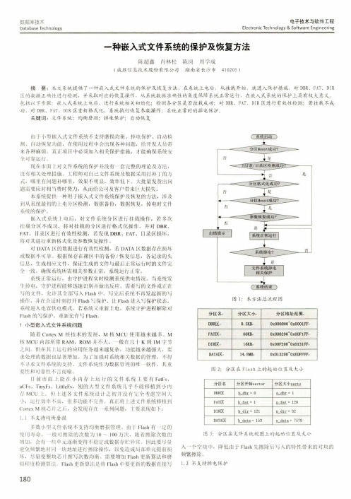
数据库技术D a ta b a se T e c h n o lo g y电子技术与软件工程E le c tro n ic T e c h n o lo g y& S o ftw a re E n g in e e rin g 一种嵌入式文件系统的保护及恢复方法陈超鑫肖林松陈岗周学成(成胜信息技术股份有限公司湖南省长沙市410205 )摘要:衣文系统提供了一种嵌入式文件系统的保护及恢复方法,在系统上电后,从挂栽开始,就进入保护措施,对D B R、F A T、D I R 区的数据正确性进行检测,并采取对应的恢复操作,从系统数据准确性的角度保障系统正常运行,在嵌入式系统的保护上具有极大意义。
包括以下步骤:嵌入式系统上电后,进行系统相关初始化;检测各分区是否挂载成功;对D B R、F A T、D I R区进行有效性检测;若桂载不成 功,对D B R、F A T、D I R区重新格式化,系统执行恢复参数操作;系统正常时的掉电保护。
关键词:文件系统;均衡磨损;掉电保护;自动恢复由于小型嵌入式文件系统不支持磨损均衡、掉电保护、自动检测、自动恢复功能,在使用过程中会出现各种问题,给开发人员带来各种麻烦。
釭正项目中必须加入相关保护措施,才能确保系统安全可靠运行。
现在市面上对文件系统的保护并没有一套完整的理论及方法,没何相关处理措施。
工程师对自己文件系统及数据采用打补丁的方式,哪里有M题补哪里,效果不明显,效率低下。
人批量发货出问题需要应对相3费时费力,从而给公司及客户带来巨大损失。
本系统提供•种用于嵌入式文件系统保护及恢H的方法,涉及到从系统最初的h电分区检测,数据备份,数据恢复,掉电时文件系统的保护。
嵌入式系统上电后,对文件系统分区进行挂载操作,若多次挂载分区不成功,将对挂载的分K进行格式化操作。
并对D B R、F A T、目录K进行有效性检测,若发现D B R、F A T、目录区损坏,将对其进行重新格式化及参数恢M操作。
嵌入式文件系统SD的操作

性能记录仪研发中遇到的数据存储
S D卡嵌人式文件系统是基于 S D卡 需要按整块进行存储的特性建立起
和数据交换的问 题, R 嵌人 在A Mg
式处理器和林 O 一 操作系统基础 / C Sn
上采用 S D卡设计开发 了一种嵌人 式文件系统 ,该系统具有支持多操 作系统 、易于移植和存储速度快 的
特点。
MD2 4 义了两种命令: C (plao S A MDA pc i i n D卡接收到单块写命令 C t s e ii c mma d 和 GE P c fc o n) N- 后 ,卡将发送给主机一个应答令 c (ee cm ad, MD o nr o m n)后者可直 牌 ,并且等待主机发送一个发送数 l a
该层直接使用文件系统层 的接
其详细介绍。 1文件的创建 . 在S D卡上创建文件或 目录的
口A 函数完成对检测到数据的操 I P
作 ,而不需要考虑使用函数 的细节
P a e r l k, r a t Bo ) m e c 磁盘标志记录表, 过程就是在文件 目录表F T D 中申请
项式为 :G x= 7 x+ ;数据校验 ()x+ 3 1
采用 cRc1 6,生成多项式为 : 数据线传输,在写操作过程中,由 AO s u 信号。 G x= l+ l+ s 1 C C 校验采 D T 线传输b y ()x6 xZ x+ 。 R 7
用直接编程计算的方法, R 1采 CC 6
用 查 G x= 1+ l+ s 1 ()x 6 x Z x + 余式表 的 方法 。
R aFl ) 读文件 ; l e i (, ed i (, e Co Fl ) 关 s e 其 中创建 、读写和删 除文件是应用 程序使用的主要 函数接 口,下面对
fatfs使用例程

fatfs使用例程FatFs是一个嵌入式文件系统库,用于处理在嵌入式应用中使用的存储设备(例如SD卡、SPI存储芯片等)上的文件操作。
它由Elm Chan开发并开源,具有轻量级、可移植性强等特点,适用于各种嵌入式系统。
在使用FatFs之前,我们需要做几个准备工作。
首先,我们需要在我们的开发环境中添加FatFs库文件,并在我们的项目中引入相关的头文件。
其次,我们需要连接一个存储设备到我们的嵌入式系统,例如SD卡或SPI存储芯片。
接下来,我们将通过一个简单的示例来说明如何使用FatFs库。
我们将使用一个基于STM32F4的开发板和一个连接到内置SD卡插槽的SD卡来进行示范。
首先,在STM32CubeIDE中创建一个新的STM32工程,选择合适的开发板和芯片型号,然后通过CubeMX配置SD卡接口。
确保SD卡接口的时钟和引脚配置正确,并使能相关的中断。
然后,我们需要将FatFs库文件添加到我们的项目中。
将FatFs的源代码文件和对应的头文件复制到我们的工程目录下,并在STM32CubeIDE中添加这些文件。
在我们的工程中创建一个新的C文件,命名为"fatfs_example.c",然后在其中编写我们的FatFs使用示例代码。
```c#include "fatfs.h"#include "stdio.h"FATFS fs; /*文件系统对象*/FIL fil; /*文件对象*/FRESULT res; /* FatFs函数返回值*/UINT br, bw; /*读写的字节数*/int main(void){/*挂载文件系统*/if(f_mount(&fs, "0:", 1) != FR_OK){/*挂载失败*/printf("Mount failed.\n");while(1);}/*打开文件*/if(f_open(&fil, "test.txt", FA_OPEN_ALWAYS | FA_READ | FA_WRITE) != FR_OK){/*文件打开失败*/printf("Open failed.\n");while(1);}/*写入数据*/if(f_write(&fil, "Hello,World!", 12, &bw) != FR_OK) {/*写入失败*/printf("Write failed.\n");while(1);}/*关闭文件*/if(f_close(&fil) != FR_OK){/*关闭失败*/printf("Close failed.\n");while(1);}/*卸载文件系统*/if(f_mount(NULL, "0:", 1) != FR_OK){/*卸载失败*/printf("Unmount failed.\n");while(1);}while(1);}```在这个示例中,我们首先挂载了文件系统,然后打开了一个名为"test.txt"的文件,如果文件不存在,则会创建一个新的文件。
fatfs findfrist 介绍

fatfs findfrist 介绍FatFS是一个开源的嵌入式文件系统,由ChaN开发。
该文件系统被广泛应用于各种嵌入式设备中,如智能手机、手持设备、传感器等。
FatFS提供了一个简单易用的接口,使得开发人员能够方便地在嵌入式系统中使用文件系统进行数据存储和管理。
在FatFS中,findfirst函数是一个非常重要的函数,用于查找指定目录下的第一个文件或子目录。
这个函数的原型如下:FRESULT f_findfirst (DIR* dp, /* 已打开的目录对象指针 */FILINFO* fno /* 文件信息对象指针 */);在调用findfirst函数之前,我们需要先打开一个目录对象。
目录对象可以通过调用opendir函数来创建,该函数的原型如下:FRESULT f_opendir (DIR* dp, /* 目录对象指针 */const TCHAR* path /* 目录路径 */);在调用findfirst函数时,我们需要传入已打开的目录对象指针和一个用于存储文件信息的对象指针。
文件信息对象用于存储查找到的文件或子目录的相关信息,包括文件名、文件大小、文件属性等。
在调用findfirst函数之后,我们可以通过检查返回值来确定是否找到了指定的文件或子目录。
如果返回值为FR_OK,表示找到了文件或子目录,我们可以通过访问文件信息对象来获取相关信息。
如果返回值为FR_NO_FILE,表示未找到文件或子目录。
findfirst函数在执行过程中,会将找到的文件或子目录的相关信息填充到文件信息对象中,并返回FR_OK。
如果目录为空,则返回FR_NO_FILE。
如果发生错误,则返回其他错误码。
当我们找到了第一个文件或子目录后,可以使用findnext函数来查找下一个文件或子目录。
findnext函数的原型如下:FRESULT f_findnext (DIR* dp, /* 已打开的目录对象指针 */FILINFO* fno /* 文件信息对象指针 */);findnext函数的用法与findfirst函数类似,只是它用于查找下一个文件或子目录。
嵌入式系统简答题

述嵌入式系统的定义。
嵌入式系统是以应用为中心,以计算机技术为基础,并且软硬件可裁剪,适用于应用系统对功能、可靠性、成本、体积、功耗有严格要求的专用计算机系统。
1-2.简述嵌入式系统的组成。
从体系结构上看,嵌入式系统主要由嵌入式处理器、支撑硬件和嵌入式软件组成。
其中嵌入式处理器通常是单片机或微控制器,支撑硬件主要包括存储介质、通信部件和显示部件等,嵌入式软件则包括支撑硬件的驱动程序、操作系统、支撑软件及应用中间件等。
嵌入式系统的组成部分是嵌入式系统硬件平台、嵌入式操作系统和嵌入式系统应用。
嵌入式系统硬件平台为各种嵌入式器件、设备(如ARM、Power PC、Xscale、MIPS 等);嵌入式操作系统是指在嵌入式Linux、u CLinux、Win CE 等。
ARM7与ARM9的区别1-3.ARM7处理器使用的是(ARMv4)指令集。
ARM7 内核采用冯·诺依曼体系结构,数据和指令使用同一条总线。
内核有一条3级流水线,执行ARMv4 指令集。
1-6.ARM9采用的是(5)级流水线设计。
存储器系统根据哈佛体系结构(程序和数据空间独立的体系结构)重新设计,区分数据总线和指令总线内存管理单元MMU定义:提供专门负责存储管理的部件。
作用:实现地址映射;对地址访问进行保护和限制ARM核有多少个寄存器?ARM处理器有37个32位长的寄存器;(1)30个通用寄存器;(2)6个状态寄存器(3)1个pc2、ARM处理器:ARM处理器是英国ARM(Advanced RISC Machines)公司设计的全球领先的16/32位RISC微处理器,ARM公司通过转让RISC微处理器,外围和系统芯片设计技术给合作伙伴,使他们能用这些技术来生产各具特色的芯片。
4、异常:当正常的程序执行流程发生暂时的停止时,称之为异常,例如处理一个外部的中断请求。
6、ARM微处理器内核是如何进行异常处理的?答:1)当异常产生时,ARM内核拷贝CPSR到SPSR_<mode>,设置适当的CPSR位:改变处理器状态进入ARM态,改变处理器模式进入相应的异常模式,设置中断禁止位禁止相应中断(如果需要);保存返回地址到LR_<mode>,设置PC为相应的异常向量。
文件系统结构分析

文件系统结构分析1 嵌入式文件系统1.1嵌入式文件系统体系结构在嵌入式系统中,文件系统是嵌入式系统的一个组成模块,它是作为系统的一个可加载选项提供给用户,由用户决定是否需要加载它。
同时,它还需要满足结构紧凑、代码量小、支持多种存储设备、可伸缩、可剪裁、可移植等特点。
基于上面的要求,嵌入式文件系统在设计和实现时就要把它作为一个独立的模块来整体考虑。
特别是对文件系统内部资源的管理要做到独立性。
由于嵌入式文件系统是作为嵌入式系统的一个可选加载项提供给用户的,当用户针对其应用的特殊要求对嵌入式系统进行配置时没有选择加载文件系统,但是用户还是需要使用到系统I/O。
由于这种情况的出现就决定了嵌入式系统中的文件系统不再具有I/O设备的管理功能。
系统I/O的管理和使用接口的提供将由I/O管理模块完成,文件系统作为一个独立的自包含模块存在。
基于以上考虑,嵌入式文件系统的体系结构如图1所示。
图1 嵌入式文件系统体系结构在嵌入式文件系统的最上层是文件系统API。
文件系统的一切功能都是通过这一层提供给用户的。
同时,在整个文件系统中也只有这一层对用户是可见的。
在这一层中所提供的所有功能接口都将严格的遵循POSIX标准。
文件系统核心层是实现文件系统主要功能的模块。
在这一层中,文件系统要把用户的功能操作转化成对文件系统的抽象对象的操作。
这些操作将通过下面的功能模块最终落实到物理介质上面。
如果文件系统需要支持多种具体的文件系统格式的话,这一层还可以进一步细分成虚拟文件系统和逻辑文件系统。
块高速缓存的存在是为了提高文件系统的性能。
在这一层中缓存着以前访问过的块设备数据。
文件系统通过一定的算法来高效的管理这些数据,以提高缓冲的性能。
同时,它的存在使下层的数据操作对上层的文件操作透明,提高了文件系统的模块性。
1.2嵌入式文件系统体系的功能与特点文件系统是操作系统的重要组成部分,用于控制对存储设备的存取。
它提供对文件和目录的分层组织形式、数据缓冲(对于实时系统,允许绕过缓冲)以及对文件存取权限的控制。
基于Flash的嵌入式文件系统设计与实现
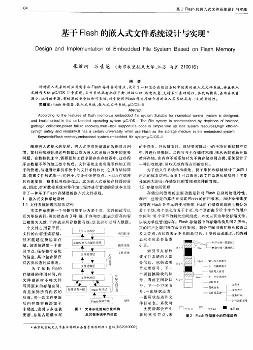
所 示 的 体 系结 构 。 由图 1可 以看 出 , 该文 件 系 统从 底 层 向上 主要 分成两大部分: 存储 空 间 的管 理 和 文件 的管 理 。 1 存 储 空 间管 理 . 2
存 储 空 间 管 理 的 主 要 功 能 是 针 对 Fa h 自身 的 物 理 特性 , ls 利用一些特定的算法来提高 F s l h的 使 用 效 率 ,加 快操 作 速 度 a 和管理 F s l h各 单 元 的使 用 频 率 。 ls a Fa h存 储 器 在组 织 上 制 , 收无 效 内容 占用 的空 间 。 回 为 了使 文 件 系 统 结构 清楚 ,便 于维 护 和 移 植 设 计 了如 图 1
序 的 管 理 , 通 用计 算 机 系 统 中的 文 件 系 统 相 比 , 具 有 结 构 简 与 它 单 、 理 文 件 形 式单 一 、 码 小 、 业 性 强 等 特 点 。 F s 管 代 专 l h存储 器 a
关 键 词 :ls Fa h存 储 器 , 入 式 系统 , 嵌 嵌入 式 文件 系统 , C OS l I / —l  ̄
Ab ta t s rc Ac or n t t e f a u e f f h c dig o h e t r s o l m e oy, as m r a embed d i s se de fe y t m Sut e or u e ia co tols s e l i abl f n m rc l n r y t m i de i e s sgn d. an i pl d m eme t d n h e b n e i t e m edd o ed pert g s se ai n y tm pC/ , OS一 Th Fi s t m i ch r c e ied e l yse e s aa tr z by eplt o baa ce d ei on f ln . gar ge ol c i , we f lr rco e ym ut-ts s pp tI S od i smpl, e p e s y t ba c l t e onpo r ai e e v r , l a k u or. c e s i u i t et u ls s sem rs r e hgh fi en ak e ou c s。i e ci — cyhi s f y a ei lyI ha a c t i u v r ai en s Fas a h sor e , gh aet nd r l abi . s eran nie s ly wh u e l h s t e t ag medu i t t t im i te embe n h dde s se . d y tm Ke wors: as m e y d Fl h m0r e b de s se , y,m ed d y tm embe dde fe y t m ,, d i s s e pC/OS一『 l I
HCC 嵌入式文件系统系列说明书
File SystemsTruly fail-safe file systemsfor all types of storage HCC has been developing embedded file systems for more than a decade and has a highly optimized range of file systems designed to meet the performance requirements of any application. Using HCC file systems will make your application more reliable and will help to protect your customer’s data. HCC file systems can be seamlessly dropped into any environment to support any storage media, RTOS, compiler or microcontroller.File Systems⏹ File SystemsFive highly optimized file systems: Each file system is finely tuned to provide the best performance for its intended environment. With full support for traditional FAT and Flash systems, developers can choose a system optimized for flexibility, performance or resource-limited environments.Extensive targ et media drivers: HCC collaborate closely with the industry’s leading storage suppliers and can provide support for almost any flash device or storage medium. We routinely supply drivers for everything from simple USB pen drives and SD cards, to the most advanced NAND and NOR flash.No-compromise fail-safety: HCC has developed truly fail-safe file systems that guarantee the highest possible data integrity.With abstractions for more than 15 real-time operating systems, and our broad range of products, our one-size-doesn’t-fit-all approach is sure to provide an optimal solution for most applications. Why not get a file system that is designed to meet your particular needs and ensure that your data is securely, efficiently and reliably cared for?⏹ FAT File SystemsAll of HCC’s FAT-com patible file system s can be used with NAND and NOR m em ories in conjunction with our fail-safe Flash Translation Layer, SafeFTL, which acts as the driver and provides wear-leveling, bad block management and error correction.FAT: High Performance 12/16/32 FAT File System. Full featured FAT file system optimized for high-performance with FAT12/16/32-compliant media. There’s extensive support for external media, including SD/MMC and Compact flash cards, or any device arranged as an array of logical sectors.THIN: File System for Resource-Limited Applications.Full-featured FAT file system for MCUs with limited resources.THIN is compatible with media such as SD/MMC and Compactflash cards. The code has been designed to provide a balance ofspeed vs. memory, with options that allow the developer to makeperformance trade-offs using available resources. This permitsa full file system to be run on a low-cost microcontroller withlimited resources.SafeFAT: Fail-safe File System. Robust, full featured fail-safeFAT file system that provides the same features as a standardFAT file system. It implements a system of journaling/transactionoperations that provide the strongest possible assurance thatall memory operations will be performed correctly, and that thesystem can recover coherently from unexpected events such asreset or power loss.⏹ Flash File SystemsSafeFLASH: Fail-safe File System. Designed for high performance and 100% fail-safety. It can be used with all NOR and NAND flash as well as any media that can simulate a block-structured array. SafeFLASH supports dynamic and static wear-leveling and provides a highly efficient solution in which data integrity is critical.TINY: Fail-safe Limited Resource File System.A full-featured, fail-safe flash file system for use in resource-constrained applications. TINY is designed for use with NOR Flash with erasable sectors <4kB. Typical devices include Atmel DataFlash AT45, MSP430 internal flash, and many serial flash devices including ST and Microchip SST Serial Flash. It eliminates many fragmentation and flash management problems and results in a compact and reliable file system that provides a full set of features, even on a low-cost controller.⏹ Advanced Fail-safetyConventional FAT file systems are not fail-safe and often experience difficulties when common problems such as power loss or unexpected resets occur. Corrupt files can sometimes be corrected using ‘check-disk’ but this requires manual intervention and often valuable data is lost.Product quality and performance can be seriously undermined by this kind of problem, but the threat can be eliminated by using a robust fail-safe file system from HCC. When used in a correctly designed system, it will guarantee that data will always be consistent. Our file systems are transaction-based but permit single file operation without reference to the rest of the system. In order to ensure the maximum integrity, our media drivers are also designed to provide fail-safe behavior. We have some of the industry’s leading experience in this area, why not talk to us about how to implement your application in the most robust way possible?⏹ Supported Flash & Media DevicesHCC supports a huge array of storage media from the most basic USB pen-drive to the most complex Solid State Drive (SSD). The number and variety of available flash devices changes at an incredible rate. Nonetheless, HCC supports hundreds of flash devices from manufacturers including Adesto, Intel, Micron, Toshiba, Hynix, Samsung, Spansion, Macronix, Microchip, Winbond and many others. We support hundreds of flash parts as well as numerous specialty devices including Solid State Drives (SSD), MLC flash and ClearNAND. All HCC file systems conform to a standard API and are fully interchangeable.Our fail-safe Flash Translation Layer, SafeFTL, can be used in conjunction with our file systems to provide wear-leveling, bad block management and error correction for almost any known device.FAT THIN SafeFAT SafeFLASH TINYNAND Flash Y*Y*Y*Y NNOR Flash Y*Y*Y*Y Y*Small Sector NOR Y*Y*Y*Y YMMC/eMMC/SD/SDHC/SDXC Y Y Y N N Compact Flash Y Y Y N NSSD Flash Y Y Y N NUSB Mass Storage Y Y Y N NRAM Y Y Y Y Y* Requires SafeFTL flash translation layer.⏹ Broad Range of Target Processors & Tools HCC usually delivers file systems with tested drivers that are fully abstracted for a particular real-time operating system, micro-controller and compiler. In most cases there is little or no integration effort required by developers. RTOS Abstractions RTOS abstractions are available for the following systems: CMX RTX, eCOS, emBOS, EUROS, FreeRTOS, Keil RTX, Nucleus, Quadros RTXC, ThreadX, μ-velOSity, μC/OS-II, and many others. Importantly, for custom schedulers and super loops, HCC offers an abstraction for ‘No RTOS’. We also offer our own eTaskSync, a small cooperative scheduler, which is designed to handle all processing and interface requirements of HCC middleware. This means that developers can choose our robust quality and outstanding performance irrespective of their legacy software. Extensive Compiler Support Eclipse/GCC, IAR Embedded Workbench, Keil ARM Compiler, Freescale CodeWarrior, Atmel AVR Studio, Green Hills Multi, Microchip MPLAB, Renesas HEW, TI Code Composer Studio, Mentor CodeSourcery, Atollic True Studio and many more. Microcontrollers ARM Cortex-M0/M1/M3/M4/R4/A8, ARM7/9/11; Atmel AVR32, SAM3/4/7/9; Freescale ColdFire, Kinetis, PowerPC, i.MX, Vybrid, QorIQ; Infineon C164, XMC1000, XMC4000; Microchip PIC24, PIC32; NXP LPC1300/1700/1800/2000/3000/4000; Renesas SuperH, RX, RL, 78k; SiliconLabs EFM32, SIM3; Spansion FM0/FM3/FM4; STMicroelectronics STM32; Texas Instruments MSP430, Stellaris, C2000, Hercules, DaVinci, Sitara, Tiva; Toshiba TMP M0/M3; ⏹ Licensing & Purchasing All HCC reusable software components are royalty-free and distributed in source form with support and maintenance included for one year with all purchases. We deliver sample projects tailored to an environment agreed with customers to ensure the quickest possible start. Visit HCC’s website to find a sample license and to obtain the contact details of your local sales representative. Or,****************************************************************************.All trademarks and registered trademarks are the property of their respective sales office: 1999 S. Bascom Avenue Suite 700, Campbell, California 95008 • Tel: +1 408 879-2619European sales offices: 24a Melville St, Edinburgh EH3 7NS Scotland, UK • Tel.: +44 7918 787 5711133 Budapest, Váci út 76., Hungary • Tel.: +36 1 450 1302info @ • sales @ • 09022016。
NAND Flash存储管理的jkffs嵌入式文件系统说明书

International Conference on Communication and Electronic Information Engineering (CEIE 2016)To establish file system in industrial storage managementHui-Zhong LiuInstitute of Applied Mathematics Hebei Academy of sciences, Shijiazhuang, 050081,ChinaE-mail:****************Aiming at the Nand flash which is widely used in industrial storage management, theembedded file system named “jkffs”is established. In “jkffs”, a direct addressingalgorithm is described; tnode-tree, variable-tnodelength are used to address most kinds ofnand flash; the method of chunk group is mentioned also. The dynamic wear-levelingalgorithm and static wear-leveling algorithm according to the different erasing times ofblock are presented in “jkffs” to realize the garbage-collection and wear-leveling.Keywords: Jkffs; Ttnode-tree; Variable-tnodelength; Tthreshold.1. IntroductionNAND Flash memory is widely used in the industrial storage management in which embedded system is the core. The log-structured file system designed according to the physical structure characteristics of NAND Flash can solve the embedded system of mass storage management issues.NAND Flash array can be divided into a series of blocks. Each block contains a number of pages, and the block is the smallest erasable unit. Erasing a block means defining all the bits as "1" (defining all bytes as “FFh”). Writing operation, through the programming, turns erased bits from "1" to "0". The unit of reading and writing is the page, the page contains data area and leisure area (OOB, out-of-band), and OOB area is used for software designer. Writing Page and erasing block are the basic operations of NAND Flash. Programming all bytes of blocks for OXFF can release space [1].2. Establishment of The File System2.1. The basic ideas of the file systemThe file system we establish is named “jkffs”. Additional information is stored in OOB area, which is designed to realize the management of NAND FLASH.All the components in the file system, including file, directory, links, devices etc., are entirely regarded as a file .Each file has a special head page store file to preserve the head of mode, length, file name, father object labeling and other information. The basic unit for writing in NAND Flash is the Page (Page) called chunk in the file system, which has different meanings. Page refers to the actual data storage areas on the NAND Flash Memory, while the chunk is the logical data storage areas allocated by the file system. Their sizes can be different.With 2048+64byte as a page of NAND Flash chips, for example, the file system use 8 Byte on OOB district to store the relative file system information [2], and design a erasing-times mark (Erase_num, 8 bits), to recover block and realize the wear-leveling. The directory structure of the file system must be built in the memory during the process of loading the system. Reading OOB contents is only needed to scan each Chunk and from the system marks in the OOB, it can be determined whether the Chunk is head or data. Then according to the contents of the file head chunk and the information such as object ID, chunk ID of data chunk, establish a corresponding object in the memory for each file. After all the Block has been scanned, it would establish the relationships of all objects, and form a kind of architecture in RAM. Thus, the file system would be loaded successfully [3].2.2. Addressing of the file systemEfficient addressing can be realized by creating a node tree. Structure definition: union jkffs_Tnode_union {union jkffs_Tnode_union *internal[8];}This is a pointer array of length 8. The node tree at the bottom, created according to this structure, becomes the leaf nodes and the middle is internal node. They have the same structure. When the nodes is the internal nodes, each element of the array will point to the next layer of child node; When the node is the leaf node, the array will be splitted into 16 long integer with N bits (Tnodelength), which is the storage location of the file contents in the flash (that is, chunkid).The Tnodelength of leaf nodes determines the maximum addressed space for the file system. For example, Tnodelength = 16, means it can represent 216 =65536 chunk.. As for a NAND flash with 2K chunk , the largest flash address space c is 128 M.It is very convenient to find the files through the node tree. Each tnode used by the internal node has 8 pointers, so three binary codes are needed to index it,therefore when the tree grows a layer high, three codes would be added into the ChunkID. In turn, each three nonzero ChunkID represents a layer of the internal nodes. Meanwhile, each Tnode used by leaf nodes has 16 pointers, so four binary codes are needed to index it.When tnode structure just started to be built, only the lowest level tnode would be established. And when the number of the Chunk was more than 16, an internal tnode would be established in the tree, and NO. 0 pointer would point to the Lowest Level Tnode. While more and more Chunk is read, new tnode will be added and the node tree is also more and more higher.2.3. Variable-Tnodelength in the node treeTnodelength of bottom node in the node tree determines the maximum space which can be addressed by file system . If The size of the chunk is 512 byte, 32 MB NAND Flash need 65536 chunks, and it needs 16 bit to index chunk. Similarly, 64MB nand flash needs at least 17 bit to index all the chunk and 128 MB NAND Flash needs18 bit. In order to facilitate processing, the tnodeSize must be the multiple of 32bit, tnodeSize = (tnodelength * 16) / 8, the unit is Byte. Tnodelength represents the length, because the Tnode of level 0 is 16 physical chunk index. From the foregoing, tnodelength is the size of physical chunk index, and the unit is bit. In order to make tnodeSize the multiple of 4 Byte, 64 M flash’s chunk index bits has to be 18 bit at least. Thus tnodelength = 18 can directly addressed 128 MThe way by increasing tnode-length can realize the management of the most large capacity of NAND Flash on the market at present, say, tnodelength = 20, the file system has the maximum space: 220 * 2 K = 2G for addressing. But such established node tree occupy too much RAM space in embedded system, which affects system performance, and it is not quite flexible for the protean design of embedded system.In system initialization process the information of NAND Flash is first read, the total number of pages can be obtained by multiplying blocks of Flash ( nblocks) by pages of each block, which means that file system need to manage these pages, and then figure out tnodelength of bottom node .specific algorithm is as follows:1) C alculated the total number of pages x = nChunksPerBlock * nBlocks2) w hen X > 1, shift X 1 to right ,bits= bits+13) r epeat , until x <= 14) i f X is odd number,X=X+15) endFlow chart as shown in Fig. 1Bits is bit length, and assign to tnodelength. This way can solve the problem that fixed tnodelength occupies too much RAM in the system, and can manageFig. 1 Tnode-length algorithm flow chartIn the actual system design, if bits is too large, Chunk array can be considered. Make one Chunk to match more pages, through which can reduce the tnodelength.Thus,the goal of managing NAND Flash memory can also be achieved. That is, through synthesizing certain chunk into a group with a same Id, may also increase the addressing chunk scope. At this time, the Pages of chunk are different. Supposing that a Chunk corresponds two pages andtwo continuous pages can becalled d_Chunk, including 4096bytes data, here d_Chunk [0], d_Chunk [1] correspond relevant page separately, as shown in Fig. 2:Fig. 2 Chunk array and Page relationship schemes3. Garbage- Collection and Wear-LevelingThe life of the flash memory is limited, it is determined by the maximum erasing time of the block .Therefore, wear-leveling algorithm should be design to distribute the erasing and writing operation evenly on each block and its impact on performance should be as low as possible. The process of erasing blocks and reuse it is called “garbage-collection”. Considering the using frequency of data with garbage-collection and wear-leveling, we designed two algorithms: dynamic and static wear-leveling algorithm.3.1. Dynamic wear-leveling algorithmThe working range of Dynamic wear-leveling algorithm is the updated frequently data space and unused space, it will be realized in the writing of data.Fig. 3 Garbage-collection Flow chartThe algorithm supplies a good way to manage the dynamic data in flash memory. It can guarantee a fixed number of free blocks, as well as can solve data writing delay and accumulation. Two values were used in the blockrecovery algorithm above, they are Min and TH1. Min is the number of recovered dirty block each time when the idle block list is empty. Next, TH1will be explained.In this algorithm, garbage-collection will happen when free block list is empty, while the recovery of dirty block may need to copy the effective data of dirty block first, so the erasing should be done by descending order of useless data page when recovering block, here TH1 means the lower limit of dirty block though “Aggressive Mode”, the recovery can be operated from the beginning of the list of dirty block when the value is more than that.The Min must meet the conditions for Min ≥ TH1.If Min is too large, the number of free blocks will increase, accordingly, the available memory space will reduce; If Min is too small, it cannot solve the problem of data accumulation completely. In the file system, Min is 1/10 of the total block, namely Min = nBlocks / 10, TH1 = Min / 2.3.2. The realization of static wear-levelingIn the practical application of the embedded system data storage have such characteristics: most files are small files, but large files take up most of the storage space; the blocks of small files are updated much frequently. Thus the following situation will appear: the erasing blocks of small files have more erasing times than that of big files, which leads erasing times of small files’erasing blocks will reach the upper limit of erasing times faster and the life of the whole flash memory will be used up.In order to deal with this kind of static read-only data, we designed static wear-leveling algorithm. When the garbage-collection was triggered, read the EraseNum from OOB of the erase block in the clean blocks list, which marked the erasing times, then find out biggest and smallest erasing times. Then do subtraction between them, if the value is bigger than threshold, it can be concluded that erase with minimum number of erasing stored static data, and it needed to be moved. And because the static data are usually bigger and take up more erase blocks, the number of blocks with the minimum time of erasing is more than 1. Therefore, in order to better achieve erase equilibrium, it is necessary to scan the clean block list again after moving operation, and find out the block with maximum erasing times. Specific algorithm is divided into the following steps:1)S can clean block list, and find out the blocks with the biggest and smallest erasing times, then record the number EraseMax and EraseMin respectively, and name the blocks A and B respectively.2) I f “EraseMax - EraseMin≥TH2”, erase block B store the static data, it must be done with moving operation.3) s elect one block from the free block list, copy the data of A to it; Then erase A, and then copy the data of B to A; And then put B to the dirty block list for the storage of data updated frequently.4) R epeat above three steps, until “EraseMax - EraseMin≥TH2” is false, That is, all the static data have been moved.The value of TH2 is very important in the algorithm. If the threshold is too large, the number of static file storage blocks needed to be released will be greater than that of free blocks, and effective data cannot be all received. Conversely, if threshold is too small, blocks for static data file storage cannot be released promptly, and frequent data moving will affect the performance of the system. Usually it is better to set the value of TH2 between 200 to 500. In this file system TH2 = 250.4. ConclusionAt present the most reasonable management of NAND flash memory of the file system mostly uses the log-structured design ideas, such as JFFS, yaffs, etc. The file system “jkffs ” is developed and completed .Practice has proved that “jkffs ” could flexibly manage many NAND Flash with various size at present. References1. Samsung Corp. Flash Memory K9K4G08U0M DataSheet[S], Nov. 2015.2. SUN Feng and ZHANG Fu-xin, “Research an Improvement Of YAFFSFile System”, Computer Engineering, vol. 34, pp. 258-261 March 2014.(In Chinese).3. Wookey. YAFFS Direct User Guide. 2013-07-26. http :// /.。
基于ARM的嵌入式文件系统研究与设计
收稿 时间 :0 9 0 — 3 2 0—62
2 基于L C 4 8 F 的存储 系统设计 P 2 6 和T 卡
SR P D仪器采 用 L C 4 8为嵌入式微处理器 , P2 6 数
Pout pi 产 品应 用 2 9 rd c ld Ap e 2
F T 文件 格式 是 由微软 推 出的在 MS D A — OS 和 Wid ws 系统 中使 用的一种非线性 链表式结构 的文 no 件 系统 。F T即 Fl lc t n T be文件分 配表) A i AI a i a l( e o o 的简称 ,F T文件格式将组成每个文件的数据块以指 A
Absr c : T i a e isl n r d c st ep icpl fte F ta t h sp p rfr t i to u e h rn i e o AT l y tm . e , td sg sal mb d e l y tm y h i f e s se Th n i e i n r e e d d f e s se i a p id t a dba e n LPC2 8 a d p le o TF c r s d o 46 n C/ —IEmb d e e ai g S tm , o h t tr g f OS I e d d Op r tn yse f rt edaaso a e o
额。F T文件格式 以其兼容性好、应用广泛、安全性 A 高 、数据存储共享性好等优点被作为 文件格式 应用于 嵌入式文件 系统 的设计 中。本文在基于 L C 4 8 嵌 P2 6 入式 微处理 器和 O —I C/ S l嵌入 式操作 系统 的平台上 , 详细介绍 了p F C/ S文件系统的移植 和基于 T F卡 的存 储系统 的设计。
- 1、下载文档前请自行甄别文档内容的完整性,平台不提供额外的编辑、内容补充、找答案等附加服务。
- 2、"仅部分预览"的文档,不可在线预览部分如存在完整性等问题,可反馈申请退款(可完整预览的文档不适用该条件!)。
- 3、如文档侵犯您的权益,请联系客服反馈,我们会尽快为您处理(人工客服工作时间:9:00-18:30)。
•
构建/mnt目录
在/mnt目下建立 nfs sd usb目录作为将来的设备挂接 点 构建/usr目录 /usr目录下建立 lib bin 目录作为后增加应用程序目录
•
16
3. 4.
13
Linux根文件系统目录文件的构建
•
1. 2.
构建/etc目录2
修改inittab,把第三项tty2::askfirst:-/bin/sh注释掉 修改profile,加入PATH环境变量: export PATH=/bin:/sbin:/usr/bin:/usr/sbin
3.fstab下增加以下内容: tmpfs /tmp/ tmpfs defaults 0 0 //tmp目录在系统运行时,需要进行读写操作 /dev/mtdblock/2/root yaffs defaults 1 1 //将yaffs分区挂载到root下,使得此文件夹在开发板上 可写
7
• inittab文件格式: – 如果存在/etc/inittab文件,Busybox init程序解析它, 然后按照它的指示创建各种子进程,否则使用默认的 配置创建子进程 – /etc/inittab文件中每个条目用来定义一个子进程,并 确定它的启动方法,格式如下: <id> : <runlevels> : <action> : <process>
11
Busybox的使用
• 下面我们就逐步构建我们的根文件系统: • 我们从构建/bin、/sbin、linuxrc开始
– 构建/bin、/sbin的第一个思路就是从网上下到 所有常用命令的源码,并采用交叉编译器重新 编译下载到开发板上这样编译出的命令会非常 大,不适合嵌入式领域的使用 – 嵌入式领域采用专用的工具busybox来制作制 作相应的应用程序及linuxrc文件
2
Linux根文件系统目录结构
• 一个最基本的根文件系统由以下几个目录构成,我们制 作根文件系统的过程,其实也就是构造以下目录的过程 /bin /sbin /dev /etc /lib /usr /var /proc /tmp /home /root /mnt • /bin /sbin:存放常用命令及重要的系统命令 如:ls cp ifconfig kill mount 等 • /dev 存放系统设备文件 如:/tty0 /touchscreen /sound /usb 等 一般挂载devfs或udev文件系统 • /etc 存放启动所需要的各种配置文件 如:启动时自动挂载的文件系统、自动运行的脚本、 登陆用户及密码验证、触摸屏校正文件 boa服务器配置脚本等
嵌入式文件系统
1
Linux根文件系统目录结构
• 构建可以在我们开发板上运行的根文件系统, 首先必须了解其目录结构
– Linux和UNIX的文件系统是一个以“/”为根的阶层 式的树状文件结构,“/”因此被称为根目录。所有 的文件和目录都置于根目录“/”之下 – 在早期的UNIX系统中,各个厂家各自定义了自己 的UNIX系统的文件系统构成,比较混乱 – 在Linux面世不久,就开始了对Linux文件系统进行 标准化的活动,于1994年推出了名为 FHS(Filesystem Hierarchy Standard)的Linux文件系统 层次结构标准,对根文件系统目录做了统一的规 范,形成了FHS标准
只执行一次,init进程不等待它结束 init进程监测发现子进程退出时,重新启动 它
启动完respawn进 与respawn类似,不过init进程先输出 程后 “Please press Enter to activate this console”,等用户输入回车后才启动子进程。 当系统关机时 系统重启时 即重启、关闭系统时执行的程序 init进程重启时执行的程序,通常是init程 序本身。先重新读取、解析/etc/inittab文 件,再执行restart程序
15
Linux根文件系统目录文件的构建
• 构建/lib目录
在开发板上运行交叉编译器编译出的应用程序,必须 添加动态链接库的支持 假设我们统一使用3.4.1的交叉编译器编译应用程序 需拷贝3.4.1的交叉编译器库到开发板上 cd /rootfs/lib/ cp /usr/local/arm/3.4.1/arm-linux/lib *.so* ./ -a?
14
Linux根文件系统目录文件的构建
• 构建/etc目录3
当需要增加用户验证功能时修改以下文件: ::respawn:-/bin/login 同时需要从PC机上拷贝以下文件: /etc/shadow passwd group 到/rootfs/etc下 shadow:描述用户密码信息 passwd:描述用户信息 group:描述用户分组信息 我们将除了第一行与root有关的信息保留外,其余的全部 删除 其中passwd文件: root:x:0:0:root:/root:/bin/bash改为 root:x:0:0:root:/root:/bin/ash 如想增加其它用户可使用 adduser命令自行添加
一般需挂载ramfs文件系统,由系统启动后自动存放及 修改其内容 • /tmp:用于存放临时文件,通常为空 一些需要生成临时文件的程序需要此目录,且必须保 证此目录可写,一般挂载ramfs文件系统
4
Linux根文件系统目录结构
• /proc:一般挂载proc文件系统
用来表示系统的运行状态,如:模块加载数、中 断申请与使用状态、进程运行状况等 制作时为空目录,需挂载为proc文件系统,系统 启动后由内核释放相应的文件
shutdown restart
ctrl+alt+ 按下 9 del Ctrl+Alt+Del键
按Ctrl+Alt+Del组合键时执行的程序
Linux启动流程
在系统启动前期
init进程首先启动action为sysinit、wait、once的3类子进程
在系统正常运行期间:
init进程首先启动action为respawn、askfirst的两类子进程,并监 视它们,发现某建
•
• 1. 2.
构建/etc目录1
/rootfs/etc下 inittab、fstab、profile、init.d/rcS inittab: 用来作为linuxrc的解释脚本 init.d/rcS: inittab启动的第一个脚本,一般用来挂 载系统必需的文件系统、必要的设备连接、设置IP 地址、启动其他脚本等,默认仅有mount –a fstab: 执行mount –a时,按照此文件挂载文件系统 profile:登陆完shell后自动执行此脚本,一般用来设 置需要的环境变量
– init进程是由内核启动的第一个,也是惟一的一个 用户进程,进程ID为1
– 根据配置文件决定启动哪些程序,比如执行某些 脚本、启动shell、运行用户指定的程序等。
– init进程是后续所有进程的发起者,比如init进程启 动/bin/sh程序后,才能在控制台输入各种命令。 • init进程的执行程序通常是/sbin/init或者busybox生成 的linuxrc,init进程的作用即这个程序的功能。
• 我们通常采用传入命令行参数“init = xxxxxx”指定某 个程序作为init进程运行。//root
6
Linux启动流程
• Linuxrc的执行流程如下:
•初始化控制: 根据bootloader传递进来的参数决定将打印信息 显示打印到哪个中端上 •解析inittab文件: 根据/etc/inittab文件内容启动相关进程或脚本
在系统退出时:
执行action为shutdown、restart、ctrlaltdel的3类子进程(之一 或全部)
10
Linux启动流程
以下是我们使用的开发板所采用的inittab文 件 ::sysinit:/etc/init.d/rcS //首先运行rcS作为第一个启动脚本 ::respawn:-/bin/login //调用用户、密码登陆验证进程 tty2::askfirst:-/bin/ash //启动shell脚本 ::ctrlaltdel:/bin/umount -a –r //结束时取消所有挂载根文件系统
• /root root用户的家目录
用于存放root用户所需文件,一般挂载为yaffs文件系
统,作为cramfs文件系统的可写目录
• /home 其他用户家目录,可选 • /mnt 临时文件系统挂载目录
如:usb、nfs、SD卡等
5
Linux启动流程
• 那么linuxrc程序怎么得来?都做了哪些事情呢?
Linux启动流程
8
名称
sysinit
执行条件
系统启动后最先 执行
说明
Linux启动流程
指定初始化脚本路径,只执行一次,init进 程等待它结束才继续执行其它动作
wait
once respawn askfirst
系统执行完 sysinit进程后
系统执行完wait 进程后 启动完once进程 后
只执行一次,init进程等待它结束才继续执 行其它动作
3
Linux根文件系统目录结构
• /lib:主要用于存放应用程序所需的共享库
如:ls、cp、ifconfig等系统命令及自己用交叉编译器编 译得到的应用程序
• /usr:存放的为共享、只读的程序或数据
有些目录跟根文件系统下重名,用于存放一些不是非 常紧要的程序或库,如:QT所需的库文件及字体文件
• /var:存放可变的数据,如一些系统日志文件 等
例如:ttyS0 : : askfirst : -/bin/sh id: 表示这个子进程要使用的控制台, 如果省略,则使用与init进程一样的控制台。 Runlevels: 这个字段没有意义,可以省略。 action: 表示init进程如何控制这个子进程,具体取值见后表 process: 要执行的程序,它可以是可执行程序,也可以是脚本 如果process字段前有“-”字符,这个程序被称为“交互的”