EMT6中文资料
靶向吲哚菁绿纳米探针介导的光声治疗

靶向吲哚菁绿纳米探针介导的光声治疗钟俊平;杨思华【摘要】Photoacoustic therapy is an approach using the photoacoustic effect of nanoparticle for targeting and selective destruction of cancer cells. Here, a novel functioned nanoprobe based on folic acid labeled indocyanine green-containing nanoparticle was developed to target and kill cancer cells under photoacoustic therapy. The results revealed that the nanoprobe had a high efficiency in cancer cell targeting and killing in folic acid positive EMT6 cells. The ICG-PL-PEG NPs based photoacoustic therapy would be a safe and highly efficient cancer treatment technique.%光声治疗是一种利用纳米材料的光声效应选择性破坏癌细胞的方法.本研究采用叶酸作为肿瘤靶向分子,以聚乙二醇包裹吲哚菁绿形成纳米粒子(ICG-PL-PEG-FA),利用此纳米粒子在近红外区的光吸收特性,开展光声治疗研究.实验结果表明,这种叶酸标记的纳米探针对高表达叶酸的EMT6细胞具有高靶向选择性和靶向光杀伤性.这种基于包含吲哚菁绿纳米探针的光声治疗将有潜力发展为一种安全,高效的癌症治疗技术.【期刊名称】《激光生物学报》【年(卷),期】2012(021)005【总页数】5页(P470-474)【关键词】肿瘤靶向治疗;吲哚菁绿;光声治疗;纳米粒子;聚乙二醇;叶酸【作者】钟俊平;杨思华【作者单位】华南师范大学激光生命科学研究所暨激光生命科学教育部重点实验室,广东,广州,510631;华南师范大学激光生命科学研究所暨激光生命科学教育部重点实验室,广东,广州,510631【正文语种】中文【中图分类】R318.51肿瘤是严重威胁人类健康的一类疾病,死亡率高。
T06中文资料
74HC3G06; 74HCT3G06
OUTPUT nY Z L
MATERIAL plastic plastic plastic plastic
CODE SOT505-2 SOT505-2 SOT765-1 SOT765-1
MARKING H06 T06 H06 T06
DESCRIPTION
2003 Dec 02
74HC3G06; 74HCT3G06
74HCT3G06 UNIT MIN. 4.5 0 0 −40 TYP. 5.0 − − +25 MAX. 5.5 5.5 VCC +125 V V V °C
MAX. 6.0 6.0 VCC +125
tr, tf
− 6.0 −
1000 500 400
− − −
− 6.0 −
元器件交易网
Philips Semiconductors
Product specification
Inverter with open-drain outputs
FEATURES • Wide supply voltage range from 2.0 to 6.0 V • High noise immunity • Low power dissipation • SOT505-2 and SOT765-1 package • ESD protection: HBM EIA/JESD22-A114-A exceeds 2000 V MM EIA/JESD22-A115-A exceeds 200 V. • Specified from −40 to +85 °C and −40 to +125 °C. DESCRIPTION
− 500 −
EMF7中文资料
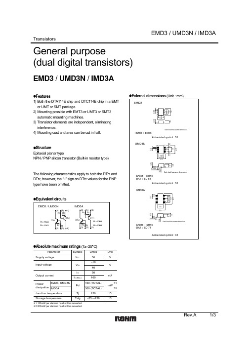
Transistors
EMF7
Power management (dual transistors)
EMF7
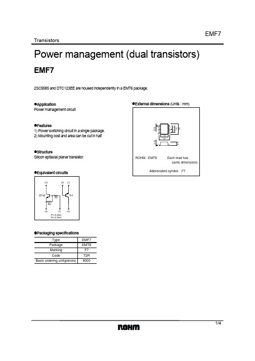
2SC5585 and DTC123EE are housed independently in a EMT6 package.
!Application Power management circuit
COLLECTOR SATURATION VOLTAGE : VCE (sat) (V)
TRANSITION FREQUENCY : fT (MHz)
BASER SATURATION VOLTAGE : VBE (sat) (mV)
1000 IC/IB=20
Pulsed
100
Ta=125°C
Ta=25°C Ta=−40°C 10
Each terminal mounted on a recommended land.
Unit V V mA ∗1 mA
mW ∗2 °C °C
EMF7
!Electrical characteristics (Ta=25°C)
Tr1
Parameter Collector-emitter breakdown voltage Collector-base breakdown voltage Emitter-base breakdown voltage Collector cut-off current Emitter cut-off current Collector-emitter saturation voltage DC current gain Transition frequency Collector output capacitance
莫勒电气 EMT6 过载继电器 中文版 说明书
A Think future. Switch to green.Building Automation SystemsIndustrial Automation Hardware and Engineering07/03 AWB2327-1446GBOverload Relay EMT6Overload monitoring system formachines operating in theEEx e areaAll brand and product names are trademarks or registered trademarks of the owner concerned.1st published 2002, edition date 02/022nd edition 07/2003See revision protocol in the “About this manual“ chapter© Moeller GmbH, 53105 BonnAuthor:Wolfgang NitschkyEditor:Heidrun RiegeTranslator:David LongAll rights reserved, including those of the translation.No part of this manual may be reproduced in any form (printed,photocopy, microfilm or any other process) or processed, duplicated or distributed by means of electronic systems without written permission of Moeller GmbH, Bonn.Subject to alteration without notice.Printed on bleached cellulose.100 % free from chlorine and acid.Before commencing the installation•Disconnect the power supply of the device.•Ensure relosing interlock that devices cannot be accidentally restarted.•Verify isolation from the supply.•Connect to earth and short-circuit.•Cover or fence off neighbouring live parts.•Follow the installation instructions (AWA) included with the device.•Only suitably qualified personnel inaccordance with EN 50110-1/-2(VDE 0105 Part 100) may work on thisdevice/system.•Before installation and before touchingthe device ensure that you are free of electrostatic charge.•The rated value of the mains voltage maynot fluctuate or deviate by more than the tolerance specified, otherwise malfunctionand hazardous states are to be expected.•Panel-mount devices may only be operated when properly installed in the cubicle orcontrol cabinet. M o e l l e r G m b HS a f e t y i n s t r u c t i o n sWarning!Dangerous electrical voltage!07/03 AWB2327-1446GBContentsAbout this manual3Target group3Abbreviations and symbols3Modification index41EMT6 thermistor machine protection relay5Preface5System overview6Unit description6–Direct temperature monitoring using thermistors 6–Thermistor protection 7–Device variants 8–Reset after triggering 10–Zero-voltage protection 10–Short-circuit monitoring of the thermistor circuit 112Configuration13Monitoring overload of motors in the EEx e area13Approvals143Installation15Notes on installation15Mounting the devices17–Terminals 18–Conductor cross-sections 19Control voltage194Operating the devices21Automatic reset21Manual reset22Reclosing interlock and short-circuit protection23Test/Reset24Device fault24Contents07/03 AWB2327-1446GBAnnex25Rating plates25Dimensions2707/03 AWB2327-1446GBAbout this manualThis manual applies for the EMT6 thermistor overload relay.It describes the overload monitoring system for theprotection of motors operating in potentially explosiveatmospheres (EEx e areas).Target group This manual addresses qualified personnel who install,commission and maintain the thermistor overload relay.Abbreviations and symbols The abbreviations and symbols used in this manual have the following meaning:EEx e“Increased safety” type of protectionTNF Rated threshold temperaturePTB P hysikalisch T echnische B undesanstalt (GermanFederal Testing Laboratory), accredited certificationauthority for devices operated in EEx e areas.PTC Positive temperature coefficient thermistor,temperature detector with positive temperaturecoefficientAbout this manual 07/03 AWB2327-1446GBX Indicates actions to be taken.For greater clarity, the name of the current chapter is shownin the header of the left-hand page and the name of thecurrent section is shown in the header of the right-handpage. Exceptions are the first page of a chapter and emptypages at the end of a chapter.Modification indexh Draws your attention to interesting tips andsupplementary information.h Note Indicates the possibility of minor material damage.jWarning!Indicates the possibility of major material damage andmajor injuries or death.EditiondatePage Subject New Change Deleted 07/038, 10,18, 19,Device types augmented j 11Section “Short-circuit monitoring of the thermistor circuit”j 14Section “Approvals”j 21Section “Automatic reset”j 22Section “Manual reset”j 25Section “Rating plates”j07/03 AWB2327-1446GB1EMT6 thermistor machineprotection relayPreface In addition to the type of protection specified for motors inpotentially explosive atmospheres and areas as specified inthe EN60079-14 and VDE0165 Part1 (German standard)standards, further provisions also apply for the respectivetypes of protection. EN 50019 demands additional measuresfor operating motors with “increased safety” type ofprotection “e”. These measures provide an enhanced degreeof safety for protection against impermissible hightemperatures and against the development of sparking andarcing on the motors, which does not usually occur undernormal operating conditions. The motor protective devicesused for this are operated outside of the EEx e area and mustbe certified by an accredited certification authority.The guidelines on the application of Directive 94/9/EC(ATEX100a) on the approximation of the laws of theMember States concerning equipment and protectivesystems intended for use in potentially explosiveatmospheres will be enforced as of 30 June 2003.The thermistor overload relay EMT6 is approved by the PTBaccording the 94/9/EC (ATEX100a) Directives.h Number of the EU certificate of compliance:PTB02ATEX3162.07/03 AWB2327-1446GB EMT6 thermistor machineprotection relaySystem overviewFigure 1 :Overload protection relays EMT6, EMT6-DB andEMT6-DBKUnit description To protect the machinery from overload, direct temperaturemonitoring systems can be used in addition to current-dependent protective devices. The EMT6 overload relaysmonitor the thermistor sensors used for monitoringtemperature and switch off the power relay in the event ofoverheat in the machinery.Direct temperature monitoring using thermistorsThe motor current can also be used to monitor motorovertemperature in addition to the indirect method oftemperature monitoring. For this, the motor manufacturerimplements integral thermistors in the motor windings.Apart from the sole purpose of motor protection, thermistorsare also used to monitor the temperature of motor andmachine bearings. They are also commonly used forUnit description07/03 AWB2327-1446GBtemperature monitoring of heating systems, heating circulation fans, in the windings of various sizes of transformers, for generator protection as well as for monitoring gaseous or liquid coolants, and temperature monitoring of non-electrical mechanical equipment. Thermistors are step-action temperature sensors, also referred to as PTC resistors or positive temperaturecoefficient resistors. Their resistance changes sharply when a defined temperature is exceeded.The thermistors are monitored by the thermistor overload protection relay EMT6.Thermistor protectionFor the protection against overtemperature, up to six PTC resistor temperature sensors to DIN 44081 PTC Resistors, or up to two temperature sensors to DIN 44082 Triple PTC Resistors with a PTC resistance of R K F 250O , or nine sensors with a PTC resistance of R K F 100O can be connected to the EMT6 terminals T1-T2 (a Fig.7, Page 18).Figure 2 :Characteristic curve for monitoring temperature with athermistorThe EMT6 switches off at R =3600O g 10% and switches on again at R =1600O g 10%. The contacts 13-14 and–20°–5°+5°+15°R e s i s t a n c e [ ]°C]EMT6 thermistor machine protection relay07/03 AWB2327-1446GB21-22 change over in the event of a shutdown caused by a signal at the thermistor input (a Fig.4, Page 16).Device variantsThe EMT6 thermistor overload protection relay is available in seven variants:•EMT6 and EMT6(230V)•EMT6-K•EMT6-DB and EMT6-DB(230V)•EMT6-KDB •EMT6-DBKThese units differ in their functions.The following table indicates the differing features of the five device-related variants:hHazardous states are also excluded in case of sensor failure when temperature is monitored with thermistors, since the unit is here switched off instantaneously.j Warning!Response of the thermistor monitoring unit must also result in a direct shutdown when the motor is controlled by means of an inverter. This must be ensured by circuit design.jWarning!A separate overload protection system must be installed for the electrical equipment.Unit description 07/03 AWB2327-1446GBEMT6EMT6(230V)EMT6-K EMT6-DBEMT6-DB(230V)EMT6-KDB EMT6-DBKFunctionAutomatic Reset+++++ Manual Reset––+++ Detection ofshort-circuit inthe sensor circuit–+–++Zero-voltagesafety––––+ Operator controlTest button––+++ Reset button––+++ Remote reset––+++ Selector switchMANUAL/AUTOreset––+++DisplayOperatingvoltage+++++ Tripping+++++ Fault short-circuit–+–++ VoltageMultiple voltageof 24 V to240V h/H+++++Single voltage230V h+–+––EMT6 thermistor machine protection relay07/03 AWB2327-1446GBReset after triggeringThe error message of the standard EMT6 is automatically reset after the equipment (motor winding) temperature has dropped to a sufficiently low level. The operating mode of the EMT6-DB, EMT6-KDB and EMT6-DBK variants can be set to “Automatic” or “Manual reset” using the selector switch. In automatic mode, the devices are reset automatically as described above. In manual mode, they are reset after the motor has cooled down.The EMT6-DB, EMT6-KDB and EMT6-DBK have anadditional option of connecting a button as a remote reset for manual mode.Zero-voltage protectionZero-voltage protection means that the error message is retained even after loss of the supply voltage. Zero-voltage protection can be enabled or disabled on the EMT6-DBK. If the equipment has not yet cooled down sufficiently after power is returned, the relays with disabled zero-voltage protection will also be tripped again. The message of devices with disabled zero-voltage protection will be lost only if power is returned after the equipment has cooled down during an extended period of power loss.jWarning!To ensure explosion-proof operation, it is permitted only to reset/switch on the motor manually after it has cooled down, or to switch it on automatically via a control interlock circuit for the motor or electrical machinery.A manual reset may be carried out on-site or from the control room by trained personnel.Unit description07/03 AWB2327-1446GBShort-circuit monitoring of the thermistor circuit The sensor circuits of all EMT6 units are equipped with a wire-break (open-circuit) safety sensor circuit. The sensor circuits of the EMT6-K, EMT6-KDB and EMT6-DBK have additional short-circuit monitoring in the sensor circuit which immediately switches off the relay when the resistive load of the sensor circuit drops below a minimum value.When using the EMT6 or EMT6-DB, a current monitor (a Fig.3, Page 12) must be used in the thermistor circuit to monitor short-circuits.jWarning!Particularly in EEx e applications, an automatic restart must be prevented after an interruption of the control voltage. This is prevented safely by means of the latching mechanism of the power relay (a Fig.4, Page 16).hZero-voltage safety can be disabled at the EMT6-DBK by means of a wire jumper between terminals Y1-Y4.hThe short-circuit monitoring of the EMT6-DBK can be disabled by means of a wire jumper between terminals Y1-Y3 (a Fig.7, Page 18).j Warning!Short-circuit monitoring is essential in the sensor circuit to monitor EEx e motors. Monitoring of short-circuits may not be disabled.hCaution!The maximum short-circuit current of the thermistor input is 1.9 mA.07/03 AWB2327-1446GB EMT6 thermistor machineprotection relayFigure 3 :Short-circuit monitoring of the thermistor circuitusing a current monitora Remote resetb STOPc START07/03 AWB2327-1446GB2ConfigurationMonitoring overload of motors in the EEx e area The “EEx e” type of protection for motors is achieved by means of special constructive measures. The motors are assigned to temperature classes based on the maximum permitted surface temperatures. The heating time t E and the ratio between startup current and rated current I A/I N are additionally calculated and specified on the motor.The safe locked-rotor time t E represents the time it takes for the rotor winding to heat up from its final rated operational temperature up to the limit temperature at a starting current of I A.However, EEx e motors are not intrinsically safe. Explosion safety is only achieved by selecting further appropriate installation measures and operating conditions (PTB testing regulations), e.g. by combination of the circuit with a correctly rated and set temperature monitoring system. The machine manufacturer equips the machine at its critical temperature points with integral thermistors to DIN44081, which are selected according to the appropriate rated threshold temperature. They develop a high resistance after their rated response temperature is exceeded. The thermistors must be compliant with the following limits according to standards:•i NAT –5K: R F550O•i NAT +5K: R f1330O•i NAT +15K: R F4000OThe thermistor overload relay monitors the thermistors and switches an auxiliary circuit when the critical temperature is exceeded.Configuration07/03 AWB2327-1446GBApprovalsThe EMT6 overload relay has been manufactured incompliance with the IEC/EC 60947 low-voltage switchgear and DIN VDE 0660-303A regulations, and fulfils the 94/9/EC (ATEX 100a) guideline for protection of EEx e motors.Furthermore, motors can be explosion protected in zones 21 and 22 (areas with combustible dusts) in compliance with EN 50281-1-1 and EN 50281-1-2.The EMT6, EMT6-DB and EMT6-DBK relays are approved by the UL and CSA for the USA and Canada.Further approvals exist for c 0102II(2)GDU s•Romania ML PAT•Russia07/03 AWB2327-1446GB3InstallationNotes on installation The notes in the current AWA2327-1454 installation manualwhich accompany the devices must be observed duringmechanical and electrical installation of the devices.j Warning!To ensure explosion-proof operation, it is permitted onlyto reset/switch on the motor manually after the thermistorhas cooled down, or to switch it on automatically via acontrol interlock circuit for the motor or electricalmachinery.A manual reset may be carried out on-site or from thecontrol room by trained personnel.j Warning!Particularly in EEx e applications, an automatic restartmust be prevented after an interruption of the controlvoltage. This is prevented safely by means of the latchingmechanism of the power relay.Installation07/03 AWB2327-1446GBFigure 4 :The circuit prevents an automatic restart.The latching mechanism of the K1M contactor relay prevents an automatic restart.N07/03 AWB2327-1446GBMounting the devicesFigure 5 :Mounting position EMT6The device can be optionally mounted on DIN-rail or screw-mounted by using a CS-TE adapter. ArrayFigure 6 :Mounting of the EMT6Installation07/03 AWB2327-1446GBTerminalsFigure 7 :Terminals a A1-A2Rated control voltage supply b 21-22Auxiliary normally closed contact c Manual/automatic reset d Mains LED (green)e Tripped LED (red)f 13-14Auxiliary normally open contactg T1-T2Thermistorh Y1-Y2Remote reseti Y1-Y4Zero-voltage safety disabled jY1-Y3Short-circuit monitoring disabledThe one-way length of the sensor cable connected to T1-T2 and the remote reset cable connected to Y1-Y2 may not exceed 250m.Short-circuit monitoring in the sensor circuit can be disabled by bridging the terminals Y1-Y3. A jumper between the terminals Y1-Y4 disables zero-voltage protection.EMT6(-K)A121221314T1T2A2Tripped Powera b gfd ae gControl voltage07/03 AWB2327-1446GBConductor cross-sectionsControl voltage EMT6... units can be operated with the following controlvoltages:Table 2:T Control voltages and voltage safetyEMT6 EMT6-K EMT6-DB EMT6-KDB EMT6-DBK EMT6(230V) EMT6-DB(230V)AC control voltage24 V to 240 V 50/60 Hz230 V 50/60 HzDC control voltage24 V to 240 V H–AC voltage safety20.4 V to 264 V 50/60 Hz195.5 V to 253 V 50/60 Hz DC voltage safety20.4 V to 264 V H–07/03 AWB2327-1446GB07/03 AWB2327-1446GB4Operating the devicesAutomatic resetThe EMT6, EMT6-K and EMT6(230V) have a setting fixed to “Automatic reset” mode. The automatic reset can also be selected with the EMT6-DB, EMT6-DB(230V), EMT6-KDB and EMT6-DBK units. The selector switch (a Fig.7, Page 18, legend c ) is set to “AUTO” for this purpose.Figure 8 :Function diagram for automatic resetAfter it has tripped, the device is reset when the equipment has cooled down.The sensor circuits of the EMT6-K, EMT6-KDB andEMT6-DBK have additional short-circuit monitoring in the sensor circuit (a Fig.9, Page 22).A1/A2T1/T2Tripped LED1314131421222122jWarning!To ensure explosion-proof operation, it is permitted only to reset/switch on the motor manually after the thermistor has cooled down, or to switch it on automatically via a control interlock circuit for the motor or electrical machinery.A manual reset may be carried out on-site or from the control room by trained personnel.Operating the devices07/03 AWB2327-1446GBFigure 9 :Function diagram of automatic reset with short-circuitmonitoringManual resetThe manual reset can also be selected with the EMT6-DB, EMT6-DB(230V), EMT6-KDB and EMT6-DBK units. The selector switch (a Fig.7, Page 18, legend c ) is set to “Manual” for this purpose.Figure 10 :Functional diagram of the manual reset (EMT6-DBKwith disabled zero-voltage protection)The sensor circuits of the EMT6-KDB and EMT6-DBK have additional short-circuit monitoring in the sensor circuit (a Fig.11, Page 23).A1/A2T1/T2Tripped LED1314131421222122A1/A2T1/T2Y1/Y2, RESETTripped LED1314131421222122Reclosing interlock and short-circuit protection07/03 AWB2327-1446GBFigure 11 :Functional diagram of the manual reset with short-circuit monitoring (EMT6-DBK with disabled zero-voltage protection)Reclosing interlock and short-circuit protectionThe EMT6-DBK features a reclosing interlock with zero-voltage protection and a short-circuit protection in the sensor circuit.Figure 12 :Functional diagram of zero-voltage protected operationand short-circuit protection in the sensor circuitA1/A2T1/T2Y1/Y2, RESETTripped LED1314131421222122jWarning!After a power interrupt, the tripped relay switch back on automatically.hThe circuit (a Fig.4, Page 16) prevents an automaticrestart of the motor after voltage recovery.A1/A2T1/T2Y1/Y2, RESETTripped LED3600 Ohm 1600 Ohm 0 Ohm1314131421222122Short-circuitOperating the devices07/03 AWB2327-1446GBTest/ResetThe relay function can be tested by means of the test button.Figure 13 :Test/Reset functional diagramDevice faulth Zero-voltage protection can be disabled by bridging terminals Y1 and Y4 (a figure 7, Page 18).hShort-circuit protection can be disabled by bridging terminals Y1 and Y3 (a figure 7, Page 18).A1/A2T1/T2Test Reset0 OhmTest/Reset1314131421222122jWarning!Faulty devices may not be opened for repairs. They may only be replaced only by qualified personnel.07/03 AWB2327-1446GBAnnexRating platesFigure 14 :EMT6Figure 15 :EMT6(230V)AC 24...240V 50/60Hz DC 24 (240V)EMT6U e 240Ve AC-15EMT6(230V)AC 230V 50/60Hz U e 240V6Ae AC-15Figure 16 :EMT6-KAC 24...240V 50/60Hz DC 24 (240V)EMT6-KAnnex07/03 AWB2327-1446GBFigure 17 :EMT6-DB Figure 18 :EMT6-DB(230V)AC 24...240V 50/60Hz DC 24 (240V)EMT6-DBU e 240Ve AC-15AC 230V 50/60Hz EMT6-DB (230V)U e 240Ve AC-15Figure 19 :EMT6-KDB Figure 20 :EMT6-DBKAC 24...240V 50/60Hz DC 24 (240V)EMT6-KDBAC 24...240V 50/60Hz DC 24 (240V)EMT6-DBKU e 240Ve AC-15Dimensions 2707/03 AWB2327-1446GB DimensionsFigure 21 :Dimensions of the EMT6...For Moeller Electric Sales and Support call (866) 595-9616Moeller GmbHIndustrieautomationHein-Moeller-Straße 7–11D-53115 BonnE-Mail:****************Internet: © 2002 by Moeller GmbHSubject to alterationAWB2327-1446GB I M-D/I M-D/xx 07/03Printed in the Federal Republic of Germany (02/04)4*p a t p k s#n m-y-,*Article No.: 267010AThink future. Switch to green.For Moeller Electric Sales and Support call (866) 595-9616。
MAX4666EPE中文资料

For free samples & the latest literature: , or phone 1-800-998-8800.For small orders, phone 1-800-835-8769.General DescriptionThe MAX4664/MAX4665/MAX4666 quad analog switch-es feature 5Ωmax on-resistance. On-resistance is matched between switches to 0.5Ωmax and is flat (0.5Ωmax) over the specified signal range. Each switch can handle Rail-to-Rail ®analog signals. The off-leakage cur-rent is only 5nA max at +85°C. These analog switches are ideal in low-distortion applications and are the pre-ferred solution over mechanical relays in automatic test equipment or in applications where current switching is required. They have low power requirements, require less board space, and are more reliable than mechanical relays.The MAX4664 has four normally closed (NC) switches,the MAX4665 has four normally open (NO) switches, and the MAX4666 has two NC and two NO switches that guarantee break-before-make switching times.These switches operate from a single +4.5V to +36V supply or from dual ±4.5V to ±20V supplies. All digital inputs have +0.8V and +2.4V logic thresholds, ensuring TTL/CMOS-logic compatibility when using ±15V sup-plies or a single +12V supply.ApplicationsReed Relay Replacement PBX, PABX Systems Test EquipmentAudio-Signal Routing Communication SystemsAvionicsFeatureso Low On-Resistance (5Ωmax)o Guaranteed R ON Match Between Channels (0.5Ωmax)o Guaranteed R ON Flatness over Specified Signal Range (0.5Ωmax)o Guaranteed Break-Before-Make (MAX4666)o Rail-to-Rail Signal Handlingo Guaranteed ESD Protection > 2kV per Method 3015.7o +4.5V to +36V Single-Supply Operation ±4.5V to ±20V Dual-Supply Operation o TTL/CMOS-Compatible Control InputsMAX4664/MAX4665/MAX46665Ω, Quad, SPST,CMOS Analog Switches________________________________________________________________Maxim Integrated Products1Pin Configurations/Functional Diagrams/Truth Tables19-1504; Rev 0; 7/99Ordering Information continued at end of data sheet.Ordering InformationRail-to-Rail is a registered trademark of Nippon Motorola, Ltd.M A X 4664/M A X 4665/M A X 46665Ω, Quad, SPST,CMOS Analog Switches 2_______________________________________________________________________________________ABSOLUTE MAXIMUM RATINGSNote 1:Signals on NC_, NO_, COM_, or IN_ exceeding V+ or V- are clamped by internal diodes. Limit forward-diode current tomaximum current rating.V+ to GND..............................................................-0.3V to +44V V- to GND..............................................................+0.3V to -44V V+ to V-...................................................................-0.3V to +44V V L to GND........................................(GND - 0.3V) to (V+ + 0.3V)All Other Pins to DGND (Note 1).........(V- - 0.3V) to (V+ + 0.3V) Continuous Current (COM_, NO_, NC_) ........................±100mA Peak Current (COM_, NO_, NC_)(pulsed at 1ms, 10% duty cycle)...............................±300mAContinuous Power Dissipation (T A = +70°C)Narrow SO (derate 8.70mW/°C above +70°C)...............696mW Plastic DIP (derate 10.53mW/°C above +70°C)..............842mW Operating Temperature RangesMAX466_C_E ......................................................0°C to +70°C MAX466_E_E....................................................-40°C to +85°C Storage Temperature Range.............................-65°C to +150°C Lead Temperature (soldering, 10sec).............................+300°CELECTRICAL CHARACTERISTICS—Dual Supplies(V+ = +15V, V- = -15V, V L = +5V, V IN_H = +2.4V, V IN_L = +0.8V, T A = T MIN to T MAX , unless otherwise noted. Typical values are at T A = +25°C.) (Note 2)Stresses beyond those listed under “Absolute Maximum Ratings” may cause permanent damage to the device. These are stress ratings only, and functional operation of the device at these or any other conditions beyond those indicated in the operational sections of the specifications is not implied. Exposure to absolute maximum rating conditions for extended periods may affect device reliability.ELECTRICAL CHARACTERISTICS—Dual Supplies (continued)MAX4664/MAX4665/MAX46665Ω, Quad, SPST,CMOS Analog Switches (V+ = +15V, V- = -15V, V L= +5V, V IN_H= +2.4V, V IN_L= +0.8V, T A= T MIN to T MAX, unless otherwise noted. Typical values are atT A= +25°C.) (Note 2)_______________________________________________________________________________________3M A X 4664/M A X 4665/M A X 46665Ω, Quad, SPST,CMOS Analog Switches 4_______________________________________________________________________________________ELECTRICAL CHARACTERISTICS—Single Supply(V+ = +12V, V- = 0, V L = +5V, V IN_H = +2.4V, V IN_L = +0.8V, T A = T MIN to T MAX , unless otherwise noted. Typical values are at T A = +25°C.)ELECTRICAL CHARACTERISTICS—Single Supply (continued)MAX4664/MAX4665/MAX46665Ω, Quad, SPST,CMOS Analog Switches (V+ = +12V, V- = 0, V L= +5V, V IN_H= +2.4V, V IN_L= +0.8V, T A= T MIN to T MAX, unless otherwise noted. Typical values are at T A= +25°C.)(Note 2)Note 2:The algebraic convention, where the most negative value is a minimum and the most positive value a maximum, is used in this data sheet.Note 3:Guaranteed by design.Note 4:∆R ON= R ON(MAX)- R ON(MIN).Note 5:Flatness is defined as the difference between the maximum and minimum value of on-resistance as measured over the specified analog signal range.Note 6:Leakage parameters are 100% tested at maximum-rated hot temperature and guaranteed by correlation at +25°C.Note 7:Off-isolation = 20log10[V COM_/ (V NC_or V NO_)], V COM_= output, V NC_or V NO_= input to off switch.Note 8:Between any two switches.Note 9:Leakage testing at single supply is guaranteed by testing with dual supplies._______________________________________________________________________________________5M A X 4664/M A X 4665/M A X 46665Ω, Quad, SPST,CMOS Analog Switches 6_______________________________________________________________________________________Typical Operating Characteristics(T A = +25°C, unless otherwise noted.)2.03.02.54.03.55.04.55.56.56.07.0-20-10-5-1505101520ON-RESISTANCEV COM (V)R O N (Ω)1.52.52.03.53.04.54.05.0-15-50-1051015ON-RESISTANCE vs. V COMAND TEMPERATURE (DUAL SUPPLIES)V COM (V)R O N (Ω)421086121416180693121518212427303336ON-RESISTANCE vs. V COM(SINGLE SUPPLY)V COM (V)R O N (Ω)3.04.54.03.55.05.56.06.57.07.58.0042681012ON-RESISTANCE vs. V COMAND TEMPERATURE (SINGLE SUPPLY)V COM (V)R O N (Ω)040201008060120140160180-10-6-4-8-22410ON/OFF TIMES vs. V COM(DUAL SUPPLIES)V COM (V)t O N , t O F F (n s )680.0110k 1010.11001k 100k-40-10520-253550100958065ON/OFF-LEAKAGE CURRENTvs. TEMPERATURETEMPERATURE (°C)L E A K A G E (p A )-200-1002001000300400500600-20-10-5-1505101520CHARGE INJECTIONvs. V V COM (V)Q (p C )15010025020030004628101214ON/OFF TIMES vs. V COM(SINGLE SUPPLY)V COM (V)t O N , t O F F (n s )5050807011010090120130140150101213111415161720ON/OFF TIMES vs. SUPPLY VOLTAGE(DUAL SUPPIES)V+ = -V (V)t O N , t O F F (n s )18196002001003004005006000101552025303540ON/OFF TIMES vs. SUPPLY VOLTAGE(SINGLE SUPPLY)V+ (V)t O N , t O F F (n s )8060100120140160-60-20-4020406080100ON/OFF TIMES vs. TEMPERATURE(DUAL SUPPLIES)TEMPERATURE (°C)t O N , t O F F (n s )40200.0110.1101001k 10k -60-20-4020406080100SUPPLY CURRENT vs. TEMPERATURETEMPERATURE (°C)I +, I - (p A )-1000.011100.1100FREQUENCY RESPONSEFREQUENCY (MHz)L O S S (d B )-90-80-70-60-50-40-30-20-100200150250300350400-60-200-4020406080100ON/OFF TIMES vs. TEMPERATURE(SINGLE SUPPLY)TEMPERATURE (°C)t O N , t O F F (n s )10050MAX4664/MAX4665/MAX46665Ω, Quad, SPST,CMOS Analog Switches_______________________________________________________________________________________7Typical Operating Characteristics (continued)(T A = +25°C, unless otherwise noted.)M A X 4664/M A X 4665/M A X 46665Ω, Quad, SPST,CMOS Analog Switches 8_______________________________________________________________________________________Applications InformationOvervoltage ProtectionProper power-supply sequencing is recommended for all CMOS devices. Do not exceed the absolute maxi-mum ratings, because stresses beyond the listed rat-ings can cause permanent damage to the devices.Always sequence V+ on first, then V-, followed by the logic inputs, NO, or COM. If power-supply sequencing is not possible, add two small signal diodes (D1, D2) in series with supply pins (Figure 1). Adding diodes reduces the analog signal range to one diode drop below V+ and one diode drop above V-, but does not affect the devices’ low switch resistance and low leak-age characteristics. Device operation is unchanged,and the difference between V+ and V- should not exceed 44V. These protection diodes are not recom-mended when using a single supply.Off-Isolation at High FrequenciesIn 50Ωsystems, the high-frequency on-response of these parts extends from DC to above 100MHz, with a typical loss of -2dB. When the switch is turned off, how-ever, it behaves like a capacitor, and off-isolation decreases with increasing frequency. (Above 300MHz,the switch actually passes more signal turned off than turned on.) This effect is more pronounced with higher source and load impedances.Figure 1. Overvoltage Protection Using External Blocking DiodesPin DescriptionMAX4664/MAX4665/MAX46665Ω, Quad, SPST,CMOS Analog Switches_______________________________________________________________________________________9Figure 2. Switching-Time Test CircuitAbove 5MHz, circuit board layout becomes critical,and it becomes difficult to characterize the response of the switch independent of the circuit. The graphs shown in the Typical Operating Characteristics were taken using a 50Ωsource and load connected with BNC connectors to a circuit board deemed “average,”that is, designed with isolation in mind, but not using stripline or other special RF circuit techniques. For criti-cal applications above 5MHz, use the MAX440,MAX441, and MAX442, which are fully characterized up to 160MHz.Figure 3. Charge-Injection Test CircuitM A X 4664/M A X 4665/M A X 46665Ω, Quad, SPST,CMOS Analog Switches 10______________________________________________________________________________________Figure 6. Switch Off-Capacitance Test Circuit Figure 7. Switch On-Capacitance Test CircuitFigure 4. Off-Isolation Test CircuitFigure 5. Crosstalk Test CircuitMAX4664/MAX4665/MAX46665Ω, Quad, SPST,CMOS Analog SwitchesChip InformationTRANSISTOR COUNT: 108Ordering Information (continued)Package InformationM A X 4664/M A X 4665/M A X 46665Ω, Quad, SPST,CMOS Analog Switches Maxim cannot assume responsibility for use of any circuitry other than circuitry entirely embodied in a Maxim product. No circuit patent licenses are implied. Maxim reserves the right to change the circuitry and specifications without notice at any time.12____________________Maxim Integrated Products, 120 San Gabriel Drive, Sunnyvale, CA 94086 408-737-7600©1999 Maxim Integrated ProductsPrinted USAis a registered trademark of Maxim Integrated Products.Package Information (continued)。
EMH6中文资料
°C °C
0to0.1
Each lead has same dimensions
Electrical characteristics (Ta = 25°C)
Parameter Input voltage Output voltage Input current Output current DC current gain Input resistance Resistance ratio Transition frequency
Max. 0.5 − 0.3 0.18 0.5 − 61.1 1.2 −
Unit V V mA µA − kΩ − MHz
Conditions VCC=5V, IO=100µA VO=0.3V, IO=2mA IO/II=10mA/0.5mA VI=5V VCC=50V, VI=0V IO/VO=5mA/5V − − VCE=10V, IE=−5mA, f=100MHz
Appendix1-Rev1.0
元器件交易网
EMH6 / UMH6N / IMH6A
Transistors
General purpose (dual digital transistors)
EMH6 / UMH6N / IMH6A
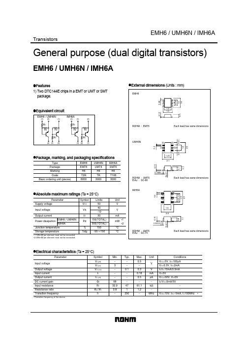
Features 1) Two DTC144E chips in a EMT or UMT or SMT package. External dimensions (Units : mm)
1.1
0.9
2.0
(5)
(2)
∗
元器件交易网
Appendix
Notes
No technical content pages of this document may be reproduced in any form or transmitted by any means without prior permission of ROHM CO.,LTD. The contents described herein are subject to change without notice. The specifications for the product described in this document are for reference only. Upon actual use, therefore, please request that specifications to be separately delivered. Application circuit diagrams and circuit constants contained herein are shown as examples of standard use and operation. Please pay careful attention to the peripheral conditions when designing circuits and deciding upon circuit constants in the set. Any data, including, but not limited to application circuit diagrams information, described herein are intended only as illustrations of such devices and not as the specifications for such devices. ROHM CO.,LTD. disclaims any warranty that any use of such devices shall be free from infringement of any third party's intellectual property rights or other proprietary rights, and further, assumes no liability of whatsoever nature in the event of any such infringement, or arising from or connected with or related to the use of such devices. Upon the sale of any such devices, other than for buyer's right to use such devices itself, resell or otherwise dispose of the same, no express or implied right or license to practice or commercially exploit any intellectual property rights or other proprietary rights owned or controlled by ROHM CO., LTD. is granted to any such buyer. Products listed in this document use silicon as a basic material. Products listed in this document are no antiradiation design.
IMX1T110中文资料
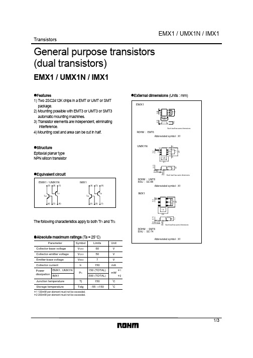
Transistors1/3General purpose transistors (dual transistors)EMX1 / UMX1N / IMX1!Features1) Two 2SC2412K chips in a EMT or UMT or SMT package.2) Mounting possible with EMT3 or UMT3 or SMT3automatic mounting machines.3) Transistor elements are independent, eliminating interference.4) Mounting cost and area can be cut in half.!StructureEpitaxial planar type NPN silicon transistor!Equivalent circuitThe following characteristics apply to both Tr 1 and Tr 2.!Absolute maximum ratings (T a = 25°C)ParameterSymbol Limits Unit V CBO 60V 50V V V CEO V EBO 7I C mA 150Tj 150˚C Tstg−55∼+150˚CP C EMX1, UMX1N 150 (TOTAL)mW IMX1300 (TOTAL)∗1∗2Collector-base voltage Collector-emitter voltage Emitter-base voltage Collector currentJunction temperature Storage temperaturePowerdissipation ∗1 120mW per element must not be exceeded.∗2 200mW per element must not be exceeded.!External dimensions (Units : mm)Transistors2/3!Electrical characteristics (T a = 25°C)ParameterSymbol BV CBO BV CEO BV EBO I CBO I EBO h FE V CE (sat)CobMin.60507−−120−−−−−−−−−2−−−0.10.15600.43.5V I C =50µA I C =1mA I E =50µA V CB =60V V EB =7V V CE =6V, IC =1mAI C /I B =50mA/5mA V V µA µA −V PFTyp.Max.Unit Conditionsf T −180−V CE =12V, I E =−2mA, f =100MHzV CB =12V, I E =0A, f =1MHzMHz ∗Collector-base breakdown voltage Collector-emitter breakdown voltage Emitter-base breakdown voltage Collector cutoff current Emitter cutoff currentDC current transfer ratio Transition frequency Collector-emitter saturation voltage Output capacitance!Electrical characteristic curvesC O L L E C T O R C U R R E N T : I C (m A )BASE TO EMITTER VOLTAGE : VBE (V)Fig.1 Grounded emitter propagationcharacteristicsC O L L E C T O R C U R R E N T : I C (m A )COLLECTOR TO EMITTER VOLTAGE : V CE (V)Fig.2 Grounded emitter outputcharacteristics ( I )C O L L E C T O R C U R R E N T : I C (m A )COLLECTOR TO EMITTER VOLTAGE : V CE (V)Fig.3 Grounded emitter output characteristics ( II )Transistors3/3D C C U R RE N T G A I N : hF ECOLLECTOR CURRENT : I C (mA)Fig.4 DC current gain vs. collector current ( I )D C C U R RE N T G A I N : hF ECOLLECTOR CURRENT : I C (mA)Fig.5 DC current gain vs. collector current ( II )C O L L E C T O R S A T U R A T I O N V O L T A G E : V C E (s a t ) (V )COLLECTOR CURRENT : I C (mA)Fig.6 Collector-emitter saturationvoltage vs. collector currentC O L L E C T O R S A T U R A T I O N V O L T A G E : V C E (s a t ) (V )COLLECTOR CURRENT : I C (mA)Fig.7 Collector-emitter saturation voltage vs. collector current ( I )C O L L E C T O R S A T U R A T I O N V O L T A G E : V C E (s a t ) (V )COLLECTOR CURRENT : I C (mA)Fig.8 Collector-emitter saturationvoltage vs. collector current ( II )C O L L E C T O R S A T U R A T I O N V O L T A G E : V C E (s a t ) (V )COLLECTOR CURRENT : I C (mA)Fig.9 Collector-emitter saturationvoltage vs. collector current ( III )EMITTER CURRENT : I E (mA)T R A N S I T I O N F R E Q U E N C Y : f T (M H z )Fig.10 Gain bandwidth product vs. emitter currentCOLLECTOR TO BASE VOLTAGE : V CB (V)EMITTER TO BASE VOLTAGE : V EB (V)C O L L EC T O R O U T P U T C A P A C I T A N C E : C o b (p F )E M I T T E R I N P U T C A P A C I T A N C E : C i b (p F )Fig.11 Collector output capacitance vs. collector-base voltageEmitter input capacitance vs. emitter-base voltage−EMITTER CURRENT : I E (mA)Fig.12 Base-collector time constant vs.emitter currentB A S EC O L L E C T O R T I M E C O N S T A N T : C c r b b (p s )AppendixAbout Export Control Order in JapanProducts described herein are the objects of controlled goods in Annex 1 (Item 16) of Export Trade ControlOrder in Japan.In case of export from Japan, please confirm if it applies to "objective" criteria or an "informed" (by MITI clause)on the basis of "catch all controls for Non-Proliferation of Weapons of Mass Destruction.Appendix1-Rev1.0。
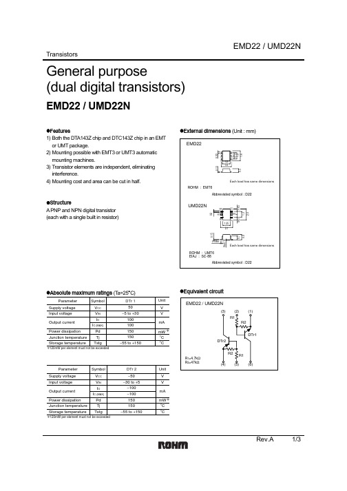
UMD22N中文资料
INPUT VOLTAGE : VI(on) (V)
100 VO=0.3V
50
20 10
5
Ta=−40°C
2
25°C 100°C
1
500m
200m 100m
100µ 200µ 500µ 1m 2m 5m 10m 20m 50m 100m OUTPUT CURRENT : IO (A)
Fig.1 Input voltage vs. output current (ON characteristics)
−1 lO/lI=20
−500m Ta=100°C
25°C
−200m
−40°C
−100m
−50m
−20m −10m −5m
−2m −1m −100µ −200µ −500µ −1m −2m −5m −10m −20m −50m −100m
OUTPUT CURRENT : IO (A)
Fig.8 Output voltage vs. output current
R2 R1 (4) (5) (6)
Rev.A
1/3
元器件交易网
Transistors
EMD22 / UMD22N
zElectrical characteristics (Ta=25°C)
DTr 1
Parameter
Input voltage
Output voltage Input current Output current DC current gain Input resistance Resistance ratio Transition frequency
25°C
200
−40°C
FMW2资料
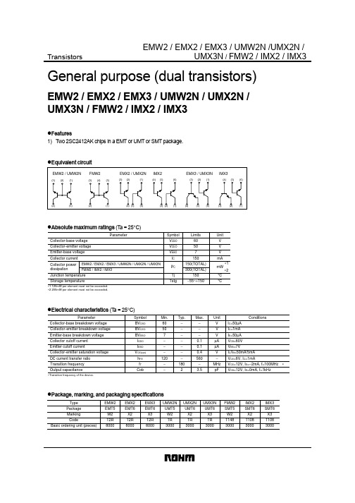
Transistors UMX3N / FMW2 / IMX2 / IMX3General purpose (dual transistors)EMW2 / EMX2 / EMX3 / UMW2N / UMX2N /UMX3N / FMW2 / IMX2 / IMX3z Features1) Two 2SC2412AK chips in a EMT or UMT or SMT package.z Equivalent circuitz Absolute maximum ratings (T a = 25°C)ParameterSymbol V CBO V CEO V EBO I C P C Tj TstgLimits 60507150300(TOTAL)150(TOTAL)EMW2 / EMX2 / EMX3 / UMW2N / UMX2N / UMX3N FMW2 / IMX2 / IMX3150−55~+150Unit V V V mA mW°C °CCollector-base voltage Collector-emitter voltage Emitter-base voltage Collector current Collector power dissipationJunction temperature Storage temperature∗1 120mW per element must not be exceeded.∗2 200mW per element must not be exceeded.∗1∗2z Electrical characteristics (T a = 25°C)ParameterSymbol Min.Typ.Max.Unit ConditionsTransition frequency BV CBO BV CEO BV EBO I CBO I EBO V CE(sat)h FE f T 60507−−−120−−−−−−−−180−−−0.10.10.4560−V V V µA µA V −MHz ∗Cob−23.5pFI C =50µA I C =1mA I E =50µA V CB =60V V EB =7VV CE =12V, I E =−2mA, f =100MHz V CB =12V, I E =0mA, f =1kHzI C /I B =50mA/5mA V CE =6V, I C =1mA∗Transition frequency of the device.Collector-base breakdown voltage Collector-emitter breakdown voltage Emitter-base breakdown voltage Collector cutoff current Emitter cutoff currentCollector-emitter saturation voltage DC current transfer ratio Output capacitancez Package, marking, and packaging specificationsType EMX2EMT6X2T2R 8000EMW2EMT5W2T2R 8000EMX3EMT6X3T2R 8000UMX2N UMT6X2TR 3000UMX3N UMT6X3TR 3000FMW2SMT5W2T1483000IMX2SMT6X2T1083000IMX3SMT6X3T1083000UMW2N UMT5W2TR 3000Package Marking CodeBasic ordering unit (pieces)Transistors UMX3N / FMW2 / IMX2 / IMX3 z External dimensions (Units : mm)AppendixAbout Export Control Order in JapanProducts described herein are the objects of controlled goods in Annex 1 (Item 16) of Export Trade ControlOrder in Japan.In case of export from Japan, please confirm if it applies to "objective" criteria or an "informed" (by MITI clause)on the basis of "catch all controls for Non-Proliferation of Weapons of Mass Destruction.Appendix1-Rev1.0。
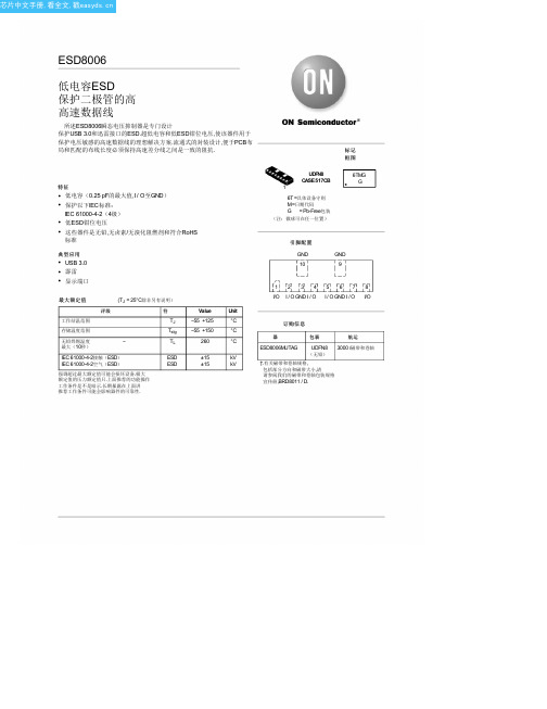
ESD8006MUTAG中文资料(ONSEMI)中文数据手册「EasyDatasheet - 矽搜」
IPP = 8 A IPP = −8 A
IPP = 16 A IPP = −16 A
IEC 61000-4-2 2级当量 (±4 kV接触, ±4 kV空气)
IEC 61000-4-2 4级相当于 (±8 kV接触, ±15 kV空气)
动态电阻
RDYN
I / O引脚到GND GND到I / O引脚
结电容
4
芯片中文手册,看全文,戳
ESD8006
TLP电流(A)
(kV)
IEC
等效V
VC = VHOLD +(我PP * R DYN )
TLP电流(A)
(kV)
IEC
等效V
NOTE:
VC,电压(V) 图 6.正 TLP的 I-V曲线
VC,电压(V) 图 7.负 TLP的 I-V曲线
TLP参数:Z
=
图 1.引脚原理
2
芯片中文手册,看全文,戳
ESD8006
电气特性
(TA = 25°C除非另有说明)
符
参数
VRWM 工作峰值电压
IR
最大反向漏电流用V
VBR
击穿电压@我
T
IT
测试电流
VHOLD IHOLD
控股反向电压 保持反向电流
RDYN IPP VC
动态电阻
最大峰值脉冲电流
钳位电压@ I
0.44 0.49
V
Max Unit
3.3
V
V
1.0
mA
V
mA
V
V
W
0.32 pF 0.25 0.25 0.16
3
芯片中文手册,看全文,戳
电压(V)
ESD8006
EMD3中文资料
TransistorsRev.A 1/3General purpose(dual digital transistors)EMD3 / UMD3N / IMD3Az Features1) Both the DTA114E chip and DTC114E chip in a EMT or UMT or SMT package.2) Mounting possible with EMT3 or UMT3 or SMT3 automatic mounting machines.3) Transistor elements are independent, eliminating interference.4) Mounting cost and area can be cut in half.z StructureEpitaxial planar typeNPN / PNP silicon transistor (Built-in resistor type)The following characteristics apply to both the DTr 1 and DTr 2, however, the “−” sign on DTr 2 values for the PNP type have been omitted.z Absolute maximum ratings (T a=25°C)ParameterSymbol Limits Unit V CC 50V −10VV IN 40I O 50mAI C (Max.)100Tj 150˚C Tstg−55∼+150˚CPd EMD3, UMD3N 150 (TOTAL)mW IMD3A 300 (TOTAL)∗1∗2Supply voltage Input voltageOutput currentJunction temperature Storage temperaturePowerdissipation ∗1 120mW per element must not be exceeded.∗2 200mW per element must not be exceeded.TransistorsRev.A 2/3z Electrical characteristics (T a=25°C)ParameterSymbol I I R 1G I R 2/R 1Min.−3−−−7300.8−−0.1−−10−10.5−0.30.880.513−1.2V V CC =5V, I O =100µA V O =0.3V, I O =10mA I O =10mA, I I =0.5mA V I =5VV CC =50V, V I =0V −V O =5V, I O =5mAV mA µA k Ω−−−Typ.Max.Unit ConditionsV I (off)V I (on)V O (on)I O (off)f T−250−V CE =10V, I E =−5mA, f =100MHz ∗MHzTransition frequency of the deviceInput voltage Output voltage Input current Output current Input resistance DC current gain Transition frequency Resistance ratioz Electrical characteristic curves DTr 1 (NPN)I N P U T V O L T A G E : V I (o n ) (V )OUTPUT CURRENT : I O (A)Fig.1 Input voltage vs. output current(ON characteristics)INPUT VOLTAGE : V I (off) (V)O U T P U T C U R R E N T : I o (A )120050010020501025Fig.2 Output current vs. input voltage (OFF characteristics)OUTPUT CURRENT : I O (A)D C C U R RE N T G A I N : G IFig.3 DC current gain vs. outputcurrentTransistorsRev.A 3/3OUTPUT CURRENT : I O (A)O U T P U T V O L T A G E : V O (o n ) (V )Fig.4 Output voltage vs. outputcurrentDTr 2 (PNP)I N P U T V O L T A G E : V I (o n ) (V )OUTPUT CURRENT : I O (A)−−−−−−−−−−−Fig.5 Input voltage vs. output current(ON characteristics)−−1−−−−200−500−100−20−50−10−2−5INPUT VOLTAGE : V I (off) (V)O U T P U T C U R R E N T : I o (A )Fig.6 Output current vs. input voltage(OFF characteristics)D C C U R RE N T G A I N : G IOUTPUT CURRENT : I O (A)−Fig.7 DC current gain vs. output current−−−−−−−−−−OUTPUT CURRENT : I O (A)O U T P U T V O L T A G E : V O (o n ) (V )−Fig.8 Output voltage vs. output currentAppendixAbout Export Control Order in JapanProducts described herein are the objects of controlled goods in Annex 1 (Item 16) of Export T rade ControlOrder in Japan.In case of export from Japan, please confirm if it applies to "objective" criteria or an "informed" (by MITI clause)on the basis of "catch all controls for Non-Proliferation of Weapons of Mass Destruction.Appendix1-Rev1.1。
UMD9N中文资料
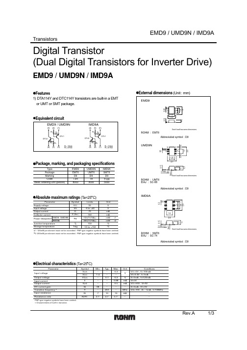
Transistors Rev.A 1/3Digital Transistor(Dual Digital Transistors for Inverter Drive)EMD9 / UMD9N / IMD9Az Features1) DTA114Y and DTC114Y transistors are built-in a EMT or UMT or SMT package.z Equivalent circuitz Package, marking, and packaging specificationsTypeEMD9EMT6D9T2R 8000UMD9N UMT6D9TR 3000IMD9A SMT6D9T1083000Package Marking CodeBasic ordering unit (pieces)z Absolute maximum ratings (T a=25°C)Parameter1 120mW per element must not be exceeded. PNP type negative symbols have been omitted.∗2 200mW per element must not be exceeded. PNP type negative symbols have been omitted.EMD9, UMD9N IMD9ALimits 50−6 to +4070300(TOTAL)150(TOTAL)−55 to +150Unit V V mA Symbol V CC V IN I O Pd Tj TstgI C (Max.)100150mA mW mW ∗1∗2°C°C Supply voltage Input voltage Output current Collector current Power dissipationStorage temperatureJunction temperaturez External dimensions (Unit : mm)z Electrical characteristics (T a=25°C)ParameterSymbol Min.Typ.Max.Unit ConditionsV I(off)V I(on)V O(on)I I I O(off)G I f T R 2/R 1−1.4−−−−683.7−−0.1−−−250−4.70.3−0.30.880.5−−∗∗ 5.7V V mA mA MHz −R 1710−13kW −V CC =5V , I O =100mA V O =0.3V , I I =1mA I O =5mA , I I =0.25mA V I =5VV CC =50V , V I =0VV CE =10V , I E = −5mA , f =100MHzI O =5mA , V O =5VInput voltage Output voltage Input current Output current DC current gainTransition frequency Input resistance Resistance ratioPNP type negative symbols have been omitted.Characteristics of built-in transistor.Transistors Rev.A 2/3z Electrical characteristics curves DTr1 (DTC114Y)I N P U T V O L T A G E : V I (o n ) (V )OUTPUT CURRENT : I O (A)−−−−−−−−−−−Fig.1 Input voltage vs. output current(ON characteristics)−−1−−−−200−500−100−20−50−10−2−5INPUT VOLTAGE : V I(off) (V)O U T P U T C U R R E N T : I o (A )Fig.2 Output current vs. input voltage(OFF characteristics)D C C U R RE N T G A I N : G IOUTPUT CURRENT : I O (A)−Fig.3 DC current gain vs. outputcurrent−−−−−−−−−−OUTPUT CURRENT : I O (A)O U T P U T V O L T A G E : V O (o n ) (V )−Fig.4 Output voltage vs. outputcurrentTransistors Rev.A 3/3z Electrical characteristics curves DTr2 (DTA114Y)I N P U T V O L T A G E : V I (o n ) (V )OUTPUT CURRENT : I O (A)−−−−−−−−−−−Fig.1 Input voltage vs. output current(ON characteristics)−−1−−−−200−500−100−20−50−10−2−5INPUT VOLTAGE : V I(off) (V)O U T P U T C U R R E N T : I o (A )Fig.2 Output current vs. input voltage(OFF characteristics)D C C U R RE N T G A I N : G IOUTPUT CURRENT : I O (A)−Fig.3 DC current gain vs. outputcurrent−−−−−−−−−−OUTPUT CURRENT : I O (A)O U T P U T V O L T A G E : V O (o n ) (V )−Fig.4 Output voltage vs. outputcurrentAppendixAbout Export Control Order in JapanProducts described herein are the objects of controlled goods in Annex 1 (Item 16) of Export T rade ControlOrder in Japan.In case of export from Japan, please confirm if it applies to "objective" criteria or an "informed" (by MITI clause)on the basis of "catch all controls for Non-Proliferation of Weapons of Mass Destruction.Appendix1-Rev1.1。
爱森·莫尔尔系列EMT6热敏过流保护器说明书
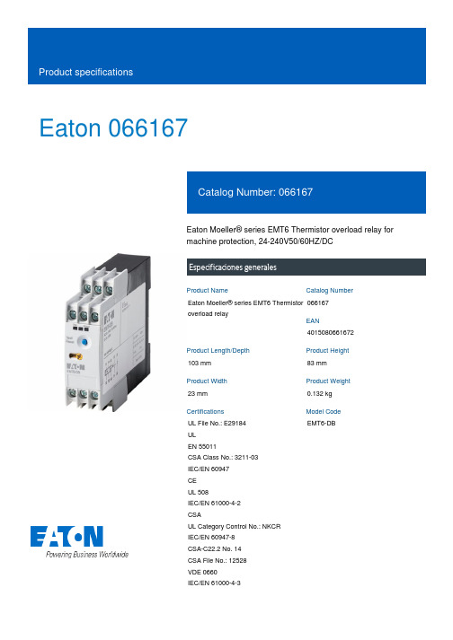
Eaton 066167Eaton Moeller® series EMT6 Thermistor overload relay for machine protection, 24-240V50/60HZ/DCEspecificaciones generalesEaton Moeller® series EMT6 Thermistor overload relay0661674015080661672103 mm 83 mm 23 mm 0.132 kg UL File No.: E29184 UL EN 55011CSA Class No.: 3211-03 IEC/EN 60947 CE UL 508IEC/EN 61000-4-2 CSAUL Category Control No.: NKCR IEC/EN 60947-8 CSA-C22.2 No. 14 CSA File No.: 12528 VDE 0660 IEC/EN 61000-4-3EMT6-DBProduct NameCatalog NumberEANProduct Length/Depth Product Height Product Width Product Weight CertificationsModel CodeScrew connectionManual or remote resettingNotifications of mains and faults via LED display Test function via separate buttonExternal reset possibleManual reset0 °C0 °C IP20As requiredIII3EMT6 thermistor overload relay for machine protectionFinger and back-of-hand proof, Protection against direct contact when actuated from front (EN 50274)6000 V AC4000 V AC250 V AC, Between the contacts and power supply, According to EN 61140250 V AC, Between the contacts, According to EN 6114010 g, Mechanical, according to IEC/EN 60068-2-27, Half-sinusoidal shock 10 msAC/DC-25 °C 60 °C 25 °C 45 °C 8 kV1 kV, Signal cable2 kV, Supply cableAccording to IEC/EN 61000-4-4 6 kVElectric connection typeFunctionsTemperature measuring range - min Temperature measuring range - max Degree of protectionMounting positionOvervoltage categoryPollution degreeProduct categoryProtectionRated impulse withstand voltage (Uimp) Safe isolationShock resistanceVoltage typeAmbient operating temperature - minAmbient operating temperature - maxAmbient operating temperature (enclosed) - min Ambient operating temperature (enclosed) - max Air dischargeBurst impulse Contact discharge Electromagnetic fields45 °C85 °CDamp heat, cyclic, to IEC 60068-2-30 Damp heat, constant, to IEC 60068-2-7810 V/m at 80 - 1000 MHz (according to IEC EN 61000-4-3) 3 V/m at 1.4 - 2 GHz (according to IEC EN 61000-4-3)1 V/m at 2.0 - 2.7 GHz (according to IEC EN 61000-4-3)10 V (according to IEC/EN 61000-4-6)Class B (EN 55011)According to IEC/EN 61000-4-5, power pulses (Surge), EMC 2 kV, symmetrical, power pulses (Surge), EMC4 kV, asymmetrical, power pulses (Surge), EMC1 x (0.5 - 2.5) mm², solid1 x (0.5 - 2.5) mm², flexible with ferrule2 x (0.5 - 1.5) mm², flexible with ferrule2 x (0.5 - 1.5) mm², solid20 - 14 AWG, solid or strandedM3.5, Terminal screw1 x 6 mm, Terminal screw, Standard screwdriver 2, Terminal screw, Pozidriv screwdriver1.2 Nm, Screw terminals 6 A0.85 - 1.1 V x Uₑ2 W at DC3.5 VA at AC24 V240 V24 V240 V24 V240 V400 V3 A at AC-14, 400 V (NC)3 A at AC-14, 380 V 400 V 415 V (NC) 3 A at AC-15, 220 V 230 V 240 V (NO)Ambient storage temperature - minAmbient storage temperature - max Climatic proofing Immunity to line-conducted interference Radio interference classSurge ratingTerminal capacityScrew size Screwdriver size Tightening torque Conventional thermal current ith of auxiliary contacts (1-pole, open)Pick-up voltagePower consumptionRated control supply voltage (Us) at AC, 50 Hz - minRated control supply voltage (Us) at AC, 50 Hz - maxRated control supply voltage (Us) at AC, 60 Hz - minRated control supply voltage (Us) at AC, 60 Hz - maxRated control supply voltage (Us) at DC - minRated control supply voltage (Us) at DC - maxRated insulation voltage (Ui)Rated operational current (Ie)3 A at AC-15, 220 V 230 V 240 V (NC) 3 A at AC-15, 220 V 230 V 240 V 3 A at AC-14, 300 V (NC) 1 A at AC-15, 300 V (NC) 3 A at AC-14, 300 V (NO)1 A at AC-15, 380 V 400 V 415 V (NO) 3 A at AC-14, 380 V 400 V 415 V (NO) 1 A at AC-15, 300 V (NO)1 A at AC-15, 380 V 400 V 415 V (NC)240 V1600 ΩMax. 6 A gG/gL, Fuse, Contacts3600 Ω600 V110 W0 W 0 W 0 A0.8 W eaton-tripping-emt6-thermistor-overload-relay-characteristic-curve-002.epseaton-tripping-emt6-thermistor-overload-relay-characteristic-curve.eps eaton-tripping-devices-relay-emt6-thermistor-overload-relay-dimensions.epseaton-tripping-thermistor-relay-emt6-dimensions.epseaton-tripping-devices-relay-emt6-thermistor-overload-relay-3d-drawing-002.eps DA-CE-ETN.EMT6-DB eaton-tripping-devices-emt6-thermistor-overload-relay-wiring-diagram.epsRated operational voltage (Ue) - max Reset resistance Short-circuit protection rating Trip resistance Voltage rating - max Number of contacts (change-over contacts)Number of contacts (normally closed contacts)Number of contacts (normally open contacts)Equipment heat dissipation, current-dependent PvidHeat dissipation capacity PdissHeat dissipation per pole, current-dependent PvidRated operational current for specified heat dissipation (In)Static heat dissipation, non-current-dependent Pvs Characteristic curveDibujoseCAD model Esquemas eléctricosEaton Corporation plc Eaton House30 Pembroke Road Dublin 4, Ireland © 2023 Eaton. All Rights Reserved. Eaton is a registered trademark.All other trademarks areproperty of their respectiveowners./socialmediaeaton-tripping-devices-auto-mode-emt6-thermistor-overload-relay-wiring-diagram.eps EMR6 - EMT6 - ETR4 brochure DA-DC-00003562.pdf DA-DC-00003971.pdf eaton-emt6-thermistor-motor-protection-relays-instruction-leaflet-il121016zu.pdf DA-CD-emt6_db DA-CS-emt6_dbFolletosInformes de certificación Instrucciones de montajemCAD model。
LTC4446EMS8E#PBF;LTC4446EMS8E#TRPBF;LTC4446IMS8E#PBF;LTC4446IMS8E#TRPBF;中文规格书,Datasheet资料
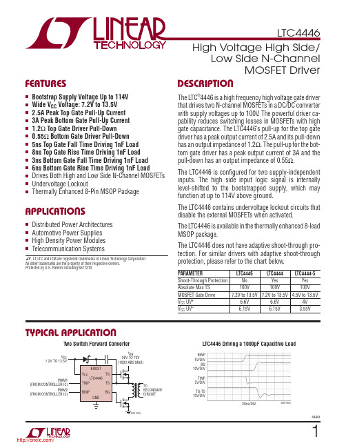
14446fTYPICAL APPLICATIONFEATURESAPPLICATIONSDESCRIPTIONLow Side N-ChannelMOSFET DriverThe L TC ®4446 is a high frequency high voltage gate driver that drives two N-channel MOSFETs in a DC/DC converter with supply voltages up to 100V . The powerful driver ca-pability reduces switching losses in MOSFETs with high gate capacitance. The L TC4446’s pull-up for the top gate driver has a peak output current of 2.5A and its pull-down has an output impedance of 1.2Ω. The pull-up for the bot-tom gate driver has a peak output current of 3A and the pull-down has an output impedance of 0.55Ω.The L TC4446 is confi gured for two supply-independent inputs. The high side input logic signal is internally level-shifted to the bootstrapped supply, which may function at up to 114V above ground.The L TC4446 contains undervoltage lockout circuits that disable the external MOSFETs when activated. The L TC4446 is available in the thermally enhanced 8-lead MSOP package.The L TC4446 does not have adaptive shoot-through pro-tection. For similar drivers with adaptive shoot-through protection, please refer to the chart below.PARAMETER L TC4446L TC4444L TC4444-5Shoot-Through Protection No Yes Yes Absolute Max TS 100V 100V 100V MOSFET Gate Drive 7.2V to 13.5V 7.2V to 13.5V 4.5V to 13.5VV CC UV +6.6V 6.6V 4V V CC UV– 6.15V 6.15V 3.55V nBootstrap Supply Voltage Up to 114V n Wide V CCVoltage: 7.2V to 13.5V n 2.5A Peak Top Gate Pull-Up Current n 3A Peak Bottom Gate Pull-Up Current n 1.2Ω Top Gate Driver Pull-Down n 0.55Ω Bottom Gate Driver Pull-Down n 5ns Top Gate Fall Time Driving 1nF Load n 8ns Top Gate Rise Time Driving 1nF Load n 3ns Bottom Gate Fall Time Driving 1nF Load n 6ns Bottom Gate Rise Time Driving 1nF Loadn Drives Both High and Low Side N-Channel MOSFETs n Undervoltage Lockoutn Thermally Enhanced 8-Pin MSOP PackagenDistributed Power Architecturesn Automotive Power Supplies n High Density Power Modules n Telecommunication SystemsT wo Switch Forward ConverterL TC4446 Driving a 1000pF Capacitive LoadL , L T , L TC and L TM are registered trademarks of Linear Technology Corporation. All other trademarks are the property of their respective owners. Protected by U.S. Patents including 6677210.V BINP 5V/DIVBG 10V/DIV TINP 5V/DIV TG-TS 10V/DIV20ns/DIV4446 TA01b/24446fPIN CONFIGURATIONABSOLUTE MAXIMUM RATINGSSupply VoltageV CC.........................................................–0.3V to 14V BOOST – TS ...........................................–0.3V to 14V TINP Voltage .................................................–2V to 14V BINP Voltage .................................................–2V to 14V BOOST Voltage ........................................–0.3V to 114V TS Voltage ...................................................–5V to 100V Operating Temperature Range (Note 2)....–40°C to 85°C Junction Temperature (Note 3) .............................125°C Storage Temperature Range ...................–65°C to 150°C Lead Temperature (Soldering, 10 sec) ..................300°C(Note 1)1234TINP BINP V CC BG8765TS TG BOOST NCTOP VIEW9MS8E PACKAGE 8-LEAD PLASTIC MSOPT JMAX = 125°C, θJA = 40°C/W , θJC = 10°C/W (NOTE 4)EXPOSED PAD (PIN 9) IS GND, MUST BE SOLDERED TO PCBORDER INFORMATIONELECTRICAL CHARACTERISTICSSYMBOL PARAMETER CONDITIONSMIN TYP MAX UNITS Gate Driver Supply, V CC V CC Operating Voltage7.213.5V I VCCDC Supply Current TINP = BINP = 0V350550μA UVLO Undervoltage Lockout ThresholdV CC Rising V CC Falling Hysteresis l l6.005.606.606.154507.206.70V V mV Bootstrapped Supply (BOOST – TS)I BOOSTDC Supply Current TINP = BINP = 0V 0.12μA Input Signal (TINP , BINP)V IH(BG)BG Turn-On Input Threshold BINP Ramping High l 2.25 2.75 3.25V V IL(BG)BG Turn-Off Input Threshold BINP Ramping Low l 1.85 2.3 2.75V V IH(TG)TG Turn-On Input Threshold TINP Ramping High l 2.25 2.75 3.25V V IL(TG)TG Turn-Off Input Threshold TINP Ramping Lowl 1.852.3 2.75V I TINP(BINP)Input Pin Bias Current ±0.01±2μA High Side Gate Driver Output (TG)V OH(TG)TG High Output Voltage I TG = –10mA, V OH(TG) = V BOOST – V TG 0.7V V OL(TG)TG Low Output Voltage I TG = 100mA, V OL(TG) = V TG –V TSl 120220mV I PU(TG)TG Peak Pull-Up Current l 1.72.5A R DS(TG)TG Pull-Down Resistance l1.22.2ΩThe l denotes the specifi cations which apply over the full operating temperature range, otherwise specifi cations are at T A = 25°C. V CC = V BOOST = 12V , V TS = GND = 0V , unless otherwise noted.LEAD FREE FINISH TAPE AND REEL PART MARKING*PACKAGE DESCRIPTION TEMPERATURE RANGE L TC4446EMS8E#PBF L TC4446EMS8E#TRPBF L TDPZ 8-Lead Plastic MSOP –40°C to 85°C L TC4446IMS8E#PBFL TC4446IMS8E#TRPBFL TDPZ8-Lead Plastic MSOP–40°C to 85°CConsult L TC Marketing for parts specifi ed with wider operating temperature ranges. *The temperature grade is identifi ed by a label on the shipping container .Consult L TC Marketing for information on non-standard lead based fi nish parts.For more information on lead free part marking, go to: http://www.linear .com/leadfree/ For more information on tape and reel specifi cations, go to: http://www.linear .com/tapeandreel//34446fNote 1: Stresses beyond those listed under Absolute Maximum Ratings may cause permanent damage to the device. Exposure to any Absolute Maximum Rating condition for extended periods may affect device reliability and lifetime.Note 2: The L TC4446E is guaranteed to meet specifi cations from 0°C to 85°C. Specifi cations over the –40°C to 85°C operatingtemperature range are assured by design, characterization and correlationELECTRICAL CHARACTERISTICS The l denotes the specifi cations which apply over the full operatingtemperature range, otherwise specifi cations are at T A = 25°C. V CC = V BOOST = 12V , V TS = GND = 0V , unless otherwise noted.SYMBOL PARAMETERCONDITIONSMINTYP MAXUNITS Low Side Gate Driver Output (BG)V OH(BG)BG High Output Voltage I BG = –10mA, V OH(BG) = V CC – V BG0.7VV OL(BG)BG Low Output Voltage I BG = 100mAl 55110mV I PU(BG)BG Peak Pull-Up Current l 23A R DS(BG)BG Pull-Down Resistance l0.55 1.1ΩSwitching Time (BINP (TINP) is Tied to Ground While TINP (BINP) is Switching. Refer to Timing Diagram)t PLH(TG)TG Low-High (Turn-On) Propagation Delay l 2545ns t PHL(TG)TG High-Low (Turn-Off) Propagation Delay l 2240ns t PLH(BG)BG Low-High (Turn-On) Propagation Delay l 1935ns t PHL(BG)BG High-Low (Turn-Off) Propagation Delay l 1430ns t DM(BGTG)Delay Matching BG Turn-Off and TG Turn-On l –151035ns t DM(TGBG)Delay Matching TG Turn-Off and BG Turn-On l –25–325ns t r(TG)TG Output Rise Time 10% – 90%, C L = 1nF 10% – 90%, C L = 10nF880ns ns t f(TG)TG Output Fall Time 10% – 90%, C L = 1nF 10% – 90%, C L = 10nF550ns ns t r(BG)BG Output Rise Time 10% – 90%, C L = 1nF 10% – 90%, C L = 10nF660ns ns t f(BG)BG Output Fall Time 10% – 90%, C L = 1nF 10% – 90%, C L = 10nF 330ns nswith statistical process controls. The L TC4446I is guaranteed over the full –40°C to 85°C operating temperature range.Note 3: T J is calculated from the ambient temperature T A and power dissipation P D according to the following formula: T J = T A + (P D • θJA °C/W)Note 4: Failure to solder the exposed back side of the MS8E package to the PC board will result in a thermal resistance much higher than 40°C/W .TYPICAL PERFORMANCE CHARACTERISTICSV CC Supply Quiescent Current vs VoltageBOOST-TS Supply Quiescent Current vs VoltageV CC Supply Current vs TemperatureV CC SUPPL Y VOL TAGE (V)00Q U I E S C E N T C U R R E N T (μA )501502002506789101112134504446 G011001234514300350400BOOST SUPPL Y VOL TAGE (V)00Q U I E S C E N T C U R R E N T (μA )501502002506789101112134004446 G021001234514300350TEMPERATURE (°C)V C C S U P P L Y C U R R E N T (μA )3503603704446 G03330300–40–25–105203550658095110125380340320310/44446fTYPICAL PERFORMANCE CHARACTERISTICSBoost Supply Current vs TemperatureOutput Low Voltage (V OL ) vs Supply VoltageOutput High Voltage (V OH ) vs Supply VoltageInput Thresholds (TINP , BINP) vs Supply VoltageInput Thresholds (TINP , BINP) vs TemperatureInput Thresholds (TINP , BINP) Hysteresis vs VoltageInput Thresholds (TINP , BINP) Hysteresis vs TemperatureV CC Undervoltage Lockout Thresholds vs TemperatureRise and Fall Time vs V CC Supply VoltageTEMPERATURE (°C)B O O S T S U P P L YC U R R E N T (μA )2503003504446 G041500–40–25–10520355065809511012540020010050SUPPL Y VOL TAGE (V)7O U T P U T V O L T A G E (m V )140104446 G058040891120016012010060121314SUPPL Y VOL TAGE (V)75T G O R B G O U T P U T V O L T A G E (V )689101512911124446 G0671314118101314SUPPL Y VOL TAGE (V)72.1T G O R B G I N P U T T H R E S H O L D (V )2.22.42.52.63.12.8911124446 G072.32.93.02.78101314TEMPERATURE (°C)–25T G O R B G I N P U T T H R E S H O L D (V )2.62.83.0954446 G082.42.22.52.72.92.32.12.053565–10–40110205080125SUPPL Y VOL TAGE (V)78375T G O R B G I N P U T T H R E S H OL D H Y S T E R E S I S (m V )425500911124446 G09400475450101314TEMPERATURE (°C)–40–25375T G O R B G I N P U T T H R E S H O L D H Y S T E R E S I S(m V )425500–105205065804446 G104004754503511095125TEMPERATURE (°C)–406.0V C C S U P L L Y V O L T A G E (V )6.16.36.46.56.7–2535654446 G116.26.62095125110–1055080SUPPL Y VOL TAGE (V)7R I S E /F A L L T I M E (n s )122830222632911124446 G12820161024618148101314/54446fTYPICAL PERFORMANCE CHARACTERISTICSRise and Fall Time vs Load CapacitancePeak Driver (TG, BG) Pull-Up Current vs TemperatureOutput Driver Pull-Down Resistance vs TemperaturePropagation Delay vs V CC Supply VoltagePropagation Delay vs TemperatureLOAD CAPACITANCE (nF)1R I S E /F A L L T I M E (n s )40506094445 G1330200357210468108070TEMPERATURE (°C)–402.0P U L L -U P C U R R E N T (A )2.22.62.83.03.4–2535654446 G142.43.22095125110–1055080TEMPERATURE (°C)–25O U T P U T D R I V E R P U L L -D O W N R E S I S T A C N E (Ω)1.21.62.0954446 G150.80.41.01.41.80.60.253565–10–40110205080125SUPPL Y VOL TAGE (V)710P R O P A G A T I O N D E L A Y (n s )121618203024911124444 G16142628228101314TEMPERATURE (°C)–402P R O P A G A T I O N D E L A Y (n s )717222737–2535654446 G1712322095125110–1055080Switching Supply Current vs Input FrequencySwitching Supply Current vs Load CapacitanceSWITCHING FREQUENCY (kHz)S U P P L Y C U R R E N T (m A )1.52.02.560010004446 G181.00.502004008003.03.54.0LOAD CAPACITANCE (nF)1S U P P L Y C U R R E N T (m A )1010013450.127896104446 G19/64446fPIN FUNCTIONSBLOCK DIAGRAMTINP (Pin 1): High Side Input Signal. Input referenced to GND. This input controls the high side driver output (TG).BINP (Pin 2): Low Side Input Signal. This input controls the low side driver output (BG).V CC (Pin 3): Supply. This pin powers input buffers, logic and the low side gate driver output directly and the high side gate driver output through an external diode con-nected between this pin and BOOST (Pin 6). A low ESR ceramic bypass capacitor should be tied between this pin and GND (Pin 9).BG (Pin 4): Low Side Gate Driver Output (Bottom Gate). This pin swings between V CC and GND.NC (Pin 5): No Connect. No connection required.BOOST (Pin 6): High Side Bootstrapped Supply. An ex-ternal capacitor should be tied between this pin and TS (Pin 8). Normally, a bootstrap diode is connected between V CC (Pin 3) and this pin. Voltage swing at this pin is from V CC – V D to V IN + V CC – V D , where V D is the forward volt-age drop of the bootstrap diode.TG (Pin 7): High Side Gate Driver Output (Top Gate). This pin swings between TS and BOOST .TS (Pin 8): High Side MOSFET Source Connection (Top Source).Exposed Pad (Pin 9): Ground. Must be soldered to PCB ground for optimal thermal performance.TIMING DIAGRAMTINP (BINP)BG (TG)BINP (TINP)TG (BG)/OPERATIONOverviewThe L TC4446 receives ground-referenced, low voltage digi-tal input signals to drive two N-channel power MOSFETs in a synchronous buck power supply confi guration. The gate of the low side MOSFET is driven either to V CC or GND, depending on the state of the input. Similarly, the gate of the high side MOSFET is driven to either BOOST or TS by a supply bootstrapped off of the switching node (TS). Input StageThe L TC4446 employs CMOS compatible input thresholds that allow a low voltage digital signal to drive standard power MOSF ETs. The LTC4446 contains an internal voltage regulator that biases both input buffers for high side and low side inputs, allowing the input thresholds (V IH = 2.75V, V IL = 2.3V) to be independent of variations inV CC. The 450mV hysteresis between V IH and V IL eliminates false triggering due to noise during switching transitions. However, care should be taken to keep both input pins (TINP and BINP) from any noise pickup, especially in high frequency, high voltage applications. The L TC4446 input buffers have high input impedance and draw negligible input current, simplifying the drive circuitry required for the inputs.Output StageA simplifi ed version of the L TC4446’s output stage is shown in Figure 1. The pull-up devices on the BG and TG outputs are NPN bipolar junction transistors (Q1 and Q2). The BG and TG outputs are pulled up to within an NPN V BE (~0.7V) of their positive rails (V CC and BOOST, respectively). Both BG and TG have N-channel MOSFET pull-down devices (M1 and M2) which pull BG and TG down to their nega-tive rails, GND and TS. The large voltage swing of the BG and TG output pins is important in driving external power MOSFETs, whose R DS(ON) is inversely proportional to the gate overdrive voltage (V GS − V TH).Rise/Fall TimeThe L TC4446’s rise and fall times are determined by the peak current capabilities of Q1 and M1. The predriver that drives Q1 and M1 uses a nonoverlapping transition scheme to minimize cross-conduction currents. M1 is fully turned off before Q1 is turned on and vice versa.Since the power MOSFET generally accounts for the ma-jority of the power loss in a converter, it is important to quickly turn it on or off, thereby minimizing the transition time in its linear region. An additional benefi t of a strong pull-down on the driver outputs is the prevention of cross- conduction current. For example, when BG turns the low side (synchronous) power MOSFET off and TG turns the high side power MOSFET on, the voltage on the TS pin will rise to V IN very rapidly. This high frequency positive voltage transient will couple through the C GD capacitance of the low side power MOSFET to the BG pin. If there is an insuffi cient pull-down on the BG pin, the voltage on the BG pin can rise above the threshold voltage of the low side power MOSFET, momentarily turning it back on. With Figure 1. Capacitance Seen by BG and TG During Switching/74446fOPERATIONboth the high side and low side MOSFETs conducting, signifi cant cross-conduction current will fl ow through the MOSFETs from V IN to ground and will cause substantial power loss. A similar effect occurs on TG due to the C GS and C GD capacitances of the high side MOSFET.The powerful output driver of the L TC4446 reduces the switching losses of the power MOSFET, which increase with transition time. The L TC4446’s high side driver is capable of driving a 1nF load with 8ns rise and 5ns fall times using a bootstrapped supply voltage V BOOST-TS of 12V while its low side driver is capable of driving a 1nF Power DissipationTo ensure proper operation and long-term reliability, the L TC4446 must not operate beyond its maximum tem-perature rating. Package junction temperature can be calculated by:T J = T A + P D (θJA)where:T J = Junction temperatureT A = Ambient temperatureP D = Power dissipationθJA = Junction-to-ambient thermal resistance Power dissipation consists of standby and switching power losses:P D = P DC + P AC + P QGwhere:P DC = Quiescent power lossP AC = Internal switching loss at input frequency, f INP QG = Loss due turning on and off the external MOSFET with gate charge QG at frequency f IN load with 6ns rise and 3ns fall times using a supply volt-age V CC of 12V.Undervoltage Lockout (UVLO)The L TC4446 contains an undervoltage lockout detector that monitors V CC supply. When V CC falls below 6.15V, the output pins BG and TG are pulled down to GND and TS, respectively. This turns off both external MOSFETs. When V CC has adequate supply voltage, normal operation will resume.APPLICATIONS INFORMATIONThe L TC4446 consumes very little quiescent current. TheDC power loss at V CC = 12V and V BOOST-TS = 12V is only(350μA)(12V) = 4.2mW.At a particular switching frequency, the internal power lossincreases due to both AC currents required to charge anddischarge internal node capacitances and cross-conduc-tion currents in the internal logic gates. The sum of thequiescent current and internal switching current with noload are shown in the Typical Performance Characteristicsplot of Switching Supply Current vs Input Frequency.The gate charge losses are primarily due to the large ACcurrents required to charge and discharge the capacitanceof the external MOSFETs during switching. For identicalpure capacitive loads C LOAD on TG and BG at switchingfrequency f IN, the load losses would be:P CLOAD = (C LOAD)(f)[(V BOOST-TS)2 + (V CC)2]In a typical synchronous buck confi guration, V BOOST-TSis equal to V CC – V D, where V D is the forward voltagedrop across the diode between V CC and BOOST. If thisdrop is small relative to V CC, the load losses can beapproximated as:P CLOAD = 2(C LOAD)(f IN)(V CC)2/84446fAPPLICATIONS INFORMATIONUnlike a pure capacitive load, a power MOSF ET’s gate capacitance seen by the driver output varies with its V GS voltage level during switching. A MOSFET’s capacitive load power dissipation can be calculated using its gate charge, Q G. The Q G value corresponding to the MOSFET’s V GS value (V CC in this case) can be readily obtained from the manufacturer’s Q G vs V GS curves. For identical MOSFETs on TG and BG:P QG = 2(V CC)(Q G)(f IN)To avoid damage due to power dissipation, the L TC4446 includes a temperature monitor that will pull BG and TG low if the junction temperature rises above 160°C. Normal operation will resume when the junction temperature cools to less than 135°C.Bypassing and GroundingThe LTC4446 requires proper bypassing on the V CC and V BOOST-TS supplies due to its high speed switching (nanoseconds) and large AC currents (Amperes). Careless component placement and PCB trace routing may cause excessive ringing.To obtain the optimum performance from the L TC4446: A. Mount the bypass capacitors as close as possible between the V CC and GND pins and the BOOST and TS pins. The leads should be shortened as much as possible to reduce lead inductance.B. Use a low inductance, low impedance ground plane to reduce any ground drop and stray capacitance. Remember that the L TC4446 switches greater than 3A peak currents and any signifi cant ground drop will degrade signal integrity.C. Plan the power/ground routing carefully. Know where the large load switching current is coming from and going to. Maintain separate ground return paths for the input pin and the output power stage.D. Keep the copper trace between the driver output pin and the load short and wide.E. Be sure to solder the Exposed Pad on the back side of the L TC4446 package to the board. Correctly soldered to a 2500mm2 doublesided 1oz copper board, the L TC4446 has a thermal resistance of approximately 40°C/W for the MS8E package. Failure to make good thermal contact between the exposed back side and the copper board will result in thermal resistances far greater than 40°C/W./94446f104446fTYPICAL APPLICATIONL T C 3722/L T C 4446 420W 36V -72V I N t o 12V /35A I s o l a t e d F u l l -B r i d g e S u p p l yL 1V I –V I 36V T /分销商库存信息:LINEAR-TECHNOLOGYLTC4446EMS8E#PBF LTC4446EMS8E#TRPBF LTC4446IMS8E#PBF LTC4446IMS8E#TRPBF。
IM06TS中文资料
IM RelayThe Best Rela ytionSlim line AND low profile2 pole telecom/signal relay, polarizedThrough Hole Types (THT), standard versionwith 5.08 mm, narrow version with 3.2 mm between the terminal rows orSurface Mount Type (SMT)Relay types:non-latching with 1 coil latching with 1 coilFeatures-Telecom/signal relay (dry circuit, test access, ringing)-Slim line10 x 6 mm, 0.39 x 0.24 inch -Low profile 5.65 mm, 0.222 inch -Minimum board-space 60 mm 2-Switching current 2 A- 2 changeover contacts (2 form C / DPDT)-Bifurcated contacts, gold plated-High sensitivity results in low nominal power consumption 140 mW for non latching 100 mW for latching version -High surge capability (1.2/50 µs and 10/700 µs) meets Bellcore GR 1089, FCC Part 68 and ITU-T K20³1500 V between open contacts ³ 2500 V between coil and contacts -High mechanical shock resistance up to 300 G functional up to 500 G survival Typical applications:-Communications equipmentLinecard application – analog, ISDN, xDSL,PABXVoice over IP -Office and business equipment -Measurement and control equipment -Consumer electronics Set top boxes, HiFi -Medical equipment Options:Surge capability ³ 2500 V between open contactsInsulation category:Supplementary insulation according IEC/EN 60950 and UL 1950Working voltage £ 300 Vrms Mains supply voltage SMT: 250 VrmsTHT: 200 VrmsRepetitive peak voltage 2500 V Pollution degree:External: 2Internal: 1Flammability classification:V-0Maximum operating temperature:85°CCSA-C22.2 No. 14-95 File No. 169679-1079886CSA-C22.2 No. 950-95UL 508 File No. E111441UL 1950 3rd ed.QC 160501-CH0001IEC/EN60950IEC Ref. Cert. No. 1176CECC 16501-003THT VersionMounting hole layoutView onto the component side of the PCB(top view)Terminal assignmentRelay - top view Non-latching type,not energized conditionDimensionsIM THT IM THT IM SMT IM SMT StandardNarrowGull WingsJ-Legsmminchmminch mminchL 10 ±0.080.393 ±0.00310 ±0.080.393 ±0.00310 ±0.080.393 ±0.00310 ±0.080.393 ±0.003W 6 ±0.080.236 ±0.0035.7 ±0.30.224 ±0.0126 ±0.080.236 ±0.0036 ±0.080.236 ±0.003H 5.65 -0.20.222 -0.008 5.85 -0.150.230 -0.0065.65 -0.20.222 -0.0085.65 -0.20.222 -0.008T 3.20.125 3.20.125N/A N/A N/AN/AT1N/AN/AN/A N/A 7.5 ±0.30.295 ±0.0112.8 ±0.20.110 ±0.007T2 5.08±0.10.200 ±0.0043.2±0.10.126 ±0.0065.08 ±0.10.200 ±0.0045.08 ±0.10.200 ±0.004D13.2 ±0.150.126 ±0.0063.2 ±0.150.126 ±0.0063.2 ±0.150.126 ±0.0063.2 ±0.150.126 ±0.006D22.2 ±0.150.087 ±0.0062.2 ±0.150.087 ±0.0062.2 ±0.150.087 ±0.0062.2 ±0.150.087 ±0.006Tw 0.40.0150.40.0150.40.0150.40.015S 0.3 ±0.050.011 ±0.0020.3 ±0.050.011 ±0.002N/AN/A N/AN/ASMT VersionGull WingsJ LegsSolder pad layoutView onto the component side of the PCB (top view)Gull WingsJ LegsLatching type, 1 coil reset conditionStandard versionNarrow versionStandard versionNarrow version1.5 1.13 3.40.1514016IM0032.1 6.80.3014064IM014.53.1510.30.45140145IM025 3.511.40.50140178IM0364.213.70.60140257IM049 6.320.40.90140574IM05128.427.3 1.201401028IM062416.845.62.402002880IM07non-latching 1 coillatching 1 coil1.5 1.13 4.1- 1.1310023IM4032.258.1- 2.2510090IM414.53.3812.1- 3.38100203IM425 3.7513.5- 3.75100250IM4364.516.2- 4.50100360IM449 6.7524.2- 6.75100810IM45129.0032.3- 9.001001440IM462418.0041.9- 18.002002880IM47Further coil versions are available on request.Ambient temperature t amb [°C]U I =Minimum voltage at 23° C after pre-energizing with nominal voltage without contact current U II =Maximum continous voltage at 23°The operating voltage limits U I and U II depend on the temperature according to the formula:U I tamb =K I · U I 23° Cand U II tamb =K Il · U Il 23° C t amb= Ambient temperatureU I tamb = Minimum voltage at ambient temperature, t amb U II tamb = Maximum voltage at ambient temperature, t ambk I , k II= Factors (dependent on temperature), see diagram* High Dielectric Version …C“All data refers to 23° C unless otherwise specified.Recommended soldering conditionsSoldering conditions according CECC 00802Vapor Phase Soldering: Temperature/Time Profile (Lead Temperature)Infrared Soldering: Temperature/Time Profile (Lead Temperature)Time (s)Time (s)T e m p e r a t u r e °CT e m p e r a t u r e °CPacking Dimensions in mm Tube for THT version - 50 relays per tube, 1000 relays per boxIM00GR3-1462037-7 IM00JR3-1462037-9 IM00TS3-1462037-5 IM00NS1-1462038-0 IM01GR0-1462037-1 IM01CGR0-1462038-4 IM01JR4-1462037-0 IM01TS0-1462037-4 IM01NS1-1462038-1 IM02GR0-1462037-9 IM02CGR0-1462038-1 IM02JR1-1462037-1 IM02TS1-1462037-3 IM02NS1-1462038-2 IM03GR1-1462037-4 IM03CGR0-1462038-2 IM03JR1-1462037-6 IM03TS1-1462037-8 IM03NS1-1462038-3 IM04GR4-1462037-2 IM04JR4-1462037-4 IM04TS4-1462037-1 IM04NS1-1462038-4 IM05GR3-1462037-4 IM05CGR0-1462038-3 IM05JR4-1462037-5 IM05TS2-1462037-2 IM05NS1-1462038-5 IM06GR2-1462037-3 IM06CGR9-1462037-9 IM06JR4-1462037-6 IM06TS2-1462037-7 IM06NS1-1462038-6 IM07GR4-1462037-7 IM07JR4-1462037-8IM07TS3-1462037-0 IM07NS1-1462038-7 IM40GR5-1462037-1 IM40JR5-1462037-2 IM40TS5-1462037-0 IM40NS1-1462038-8 IM41GR5-1462037-4 IM41JR5-1462037-5 IM41TS5-1462037-3 IM41NS1-1462038-9 IM42GR3-1462037-1 IM42JR5-1462037-7 IM42TS5-1462037-6 IM42NS2-1462038-0 IM43GR5-1462037-9 IM43JR6-1462037-0 IM43TS5-1462037-8 IM43NS2-1462038-1 IM44GR6-1462037-2 IM44JR6-1462037-3 IM44TS6-1462037-1 IM44NS2-1462038-2 IM45GR6-1462037-4 IM45JR6-1462037-5 IM45TS3-1462037-2 IM45NS2-1462038-3 IM46GR6-1462037-7 IM46JR6-1462037-8 IM46TS6-1462037-6 IM46NS2-1462038-4 IM47GR7-1462037-0 IM47JR7-1462037-1 IM47TS6-1462037-9 IM47NS2-1462038-5Relay Code TycoPart Number Relay Code TycoPart NumberOrdering InformationIM Relays4th generation slim line – low profile polarized 2 c/o telecom relay with bifurcated contacts, available as non latching or latching relay with1 coil. Nominal voltage range from 1.5... 24 V, coil power consumption of 140... 200 mW, latching relays with 1 coil 100 mW. The IM relay is available as through hole and surface mount type (J-Legs and Gull Wings) and capable to switch loads up to 60 W/62,5 VA. Dielectric strength fulfills the Bellcore requirements according GR 1089 (2,5 kV –2 / 10 µs) and FCC part 68 (1,5 kV – 10 / 160 µs). The IM is CECC/ IECQ approved and certified in accordance with IEC/EN 60950 and UL1950. Dimensions approx. 10 x 6 mm board space and 5.65 mm height.P2 Relays3rd generation polarized 2 c/o telecom relay with bifurcated contacts, available as non latching or latching relay with 1 or 2 coils. Nominal voltage range from 3 ... 24 V, coil power consumption 140 mW, latching relays with 1 coil 70 mW. The P2 relay is available as through hole or surface mount type and capable to switch currents up to 5 A. Dielectric strength fulfills the Bellcore requirements according GR 1089 (2,5 kV – 2 / 10 µs) and FCC part 68 (1,5 kV – 10 / 160 µs). Dimensions approx. 15 x 7,5 mm board space and 10 mm height.FX Relays3rd generation polarized 2 c/o telecom relay with bifurcated contacts, available as non latching or latching relay with 1 coil. Nominal voltage range from 3 ... 48 V, coil power consumption of 80 ... 260 mW for the high sensitive version, 140... 300 mW for the standard version, latching relays with 1 coil 100 mW. The FX2 relay is available as through hole type and capable to switch loads up to 60 W/62,5 VA. Dielectric strength fulfills the Bellcore requirements according GR 1089 (2,5 kV – 2 / 10 µs) and FCC part 68 (1,5 kV – 10 / 160 µs). The FX2 is CECC/IECQ approved and certified in accordance with IEC/EN 60950 and UL1950. Dimensions approx. 15 x 7,5 mm board space and 10,7 mm height.FT2 / FU2 Relays3rd generation non polarized, non latching 2 c/o telecom relay with bifurcated contacts. Nominal voltage range from 3 ... 48 V, coil power consumption 200 ... 300 mW. Most sensitive 48 V relay. Available as through hole and surface mount type. Dielectric strength fulfills the Bellcore requirements according GR 1089 (2,5 kV – 2 / 10 µs) and FCC part 68 (1,5 kV – 10 / 160 µs). The FT2/FU2 is CECC/IECQ approved and certified in accordance with IEC/EN 60950 andUL1950. Dimensions approx. 15 x 7,5 mm board space and 10 mm height.FP2 Relays3rd generation polarized 2 c/o telecom relay with bifurcated contacts, available as non latching or latching relay with 1 or 2 coils. Nominal voltage range from 3 ... 48 V, coil power consumption of 80 ...260 mW for the high sensitive version, 140... 300 mW for the standard version, latching relays with 1 coil 100 mW.. The FP2 relay is available as through hole type and capable to switch loads up to30 W/62,5 VA. Dielectric strength fulfills FCC part 68 (1,5 kV – 10 / 160 µs). The FP2 is CECC/IECQ approved. Dimensions approx.14 x 9 mm board space and 5 mm height.MT2 / MT42nd generation non polarized, non latching 2 c/o and 4 c/o telecom and signal relay with bifurcated contacts. Nominal voltage range from 4.5 ... 48 V, coil power consumption 150/200/300/400 and550 mW, and 300 mW (MT4). Dielectric strength fulfills the requirements according FCC part 68 (1,5 kV – 10 / 160 µs) for both and the Bellcore requirements according GR 1089 (2,5 kV – 2 / 10 µs) the MT4 only.Dimensions MT2 approx. 20 x 10 mm board space and 11 mm height, MT4 approx. 20 x15 mm board space and 11 mm height.D2n Relays2nd generation non polarized 2 c/o relay for telecom and various other applications. Nominal voltage range from 3 ... 48 V, coil power consumption from 150 .... 500 mW. The D2n relay is capable to switch currents up to 3 A. Dielectric strength fulfills the requirements according FCC part 68 (1,5 kV – 10 / 160 µs). Dimensions approx.20 x10 mm board space and 11,5 mm height.P1 RelaysExtremely sensitive, polarized 1 c/o relay with bifurcated contacts for a wide range of applications, available as non latching or latching relay with 1 or 2 coils. Nominal voltage range from 3 ... 24 V, coil power consumption 65 mW, latching relays with 1 coil 30 mW. The P1 relay is available as through hole or surface mount type and capable to switch currents up to 1 A. Dielectric strength fulfills the requirements according FCC part 68 (1,5 kV – 10 / 160 µs). Dimensions approx.13 x 7,6 mm board space and 7 mm height for THT or 8 mm height for SMT version.W11 RelaysLow cost, non polarized 1 c/o relay for various applications. Nominal voltage range from 3 ... 24 V, coil power consumption 450 mW, sensitive versions 200 mW. The W11 relay is capable to switch currents up to 3 A. Dielectric strength 1000 Vrms. Dimensions approx. 15,6 x 10,6 mm board space and 11,5 mm height.Reed RelaysHigh sensitive, non polarized relay for telecom and various other applications, available with 1 n/o, 2 n/o or 1c/o contacts. Nominal voltage range from 5 ... 24 V, coil power consumption 50...280 mW for 1 n/o and 125 ... 280 mW for 2 n/o or 1 c/o versions. Reedrelays are available in DIP or SIL housing and capable to switch currents up to 0,5 A. Integrated diode and/or electrostatic shield optional. Dielectric strength 1500 Vdc. Dimensions approx. 19,3 x 7 mm board space and 5 ... 7,5 mm height for DIP or 19,8 x 5 mm board space and 7,8 mm height for SIL version.Cradle RelaysExtremely reliable and mature relay family of 1st generation for various signal switching applications. Available as non polarized, polarized / latching and relay with AC coil. The benefit is the possibility of combining various contact sets from 1 up to 6 poles, single and bifurcated contacts, different contact materials with a coil voltage range from 1,5 Vdc to 220 Vac. Cradle relays are available as dust protected and hermetically sealed versions, with plug in or solder terminals and are capable to switch currents up to 5 A. Forcibly guided (linked) contact sets optional. Dielectric strength 500 Vrms. Dimensions from approx. 19 x 24 to 19x35 mm board space and30 mm height.Other RelaysWe offer a variety of different relay families for maintenance and replacement purposes. These relays are up to 60 years old now, such as Card Relay SN (V23030 / V23031 series), Small General Purpose Relay (V23006 series), Small Polarized Relay (V23063 ... V23067 and V23163 ... V23167 series). Accessories like sockets, hold down springs, etc. optional.Tyco Electronics AXICOM Ltd.Seestrasse 295 - P.O. Box 220CH-8804 Au-Wädenswil / Switzerland Phone +41 1 782 9111Fax +41 1 782 9080E-mail: axicom@Tyco Electronics Corporation POB 3608,Harrisburg, PA 17105, USA Phone +1 800-522-6752Tyco Electronics EC Trutnov s.r.o.Komenského 821CZ-541 01 Trutnov / Czech Republic E-mail: axicom@Tyco Electronics AMP GmbH Paulsternstrasse 26D-13629 Berlin / Germany Phone +49 30 386 38260Fax +49 30 386 38569E-mail: axicom@A p r i l 2002R e v . 3.01。
- 1、下载文档前请自行甄别文档内容的完整性,平台不提供额外的编辑、内容补充、找答案等附加服务。
- 2、"仅部分预览"的文档,不可在线预览部分如存在完整性等问题,可反馈申请退款(可完整预览的文档不适用该条件!)。
- 3、如文档侵犯您的权益,请联系客服反馈,我们会尽快为您处理(人工客服工作时间:9:00-18:30)。
Transistors1/4Power management (dual transistors)EMF20/UMF20N2SC4617and DTC144E are housed independently in a EMT6 or UMT6 package.z ApplicationPower management circuitz Features 1) Power switching circuit in a single package. 2) Mounting cost and area can be cut in half.z StructureSilicon epitaxial planar transistorz Equivalent circuitsz External dimensions (Units : mm)z Package, marking, and packaging specificationsType EMF20EMT6F20T2R 8000Package Marking Code Basic ordering unit (pieces)UMF20N UMT6F20TR3000Transistors2/4z Absolute maximum ratings (T a=25°C)120mW per element must not be exceeded.∗2 120mW per element must not be exceeded.Each terminal mounted on a recommended land.z Electrical characteristics (T a=25°C) Tr1ParameterSymbol BV CBO BV CEO BV EBO I CBO I EBO h FE V CE (sat)CobMin.60507−−180−−−−−−−−−2−−−0.10.13900.43.5V I C =50µA I C =1mA I E =50µA V CB =60V V EB =7VV CE =6V, I C =1mAI C /I B =50mA/5mA V V µA µA −V PFTyp.Max.UnitConditionsf T −180−V CE =12V, I E =−2mA, f =100MHzV CB =12V, I E =0A, f =1MHzMHz Collector-base breakdown voltage Collector-emitter breakdown voltage Emitter-base breakdown voltage Collector cutoff current Emitter cutoff currentDC current transfer ratio Transition frequency Collector-emitter saturation voltage Output capacitanceDTr2ParameterSymbol Min.Typ.Max.Unit Conditions∗Transition frequency f T −250−MHz V CE =10V, I E =−5mA, f =100MHz ∗Characteristics of built-in transistor.V I(off)−−0.5V V CC =5V, I O =100µA Input voltage V I(on) 3.0−−V V O =0.3V, I O =2mA V O(on)−100300mV V O =10mA, I I =0.5mA Output voltage I I −−180µA V I =5VInput current I O(off)−−500nA V CC =50V, V I =0V Output current R 132.94761.1k Ω−Input resistance G I20−−−V O =5V, I O =5mADC current gain −R 2/R 10.81.01.2−Resistance ratioTransistors3/4z Electrical characteristic curves Tr1C O L L E C T O R C U R R E N T : I C (m A )BASE TO EMITTER VOLTAGE : V BE (V)Fig.1 Grounded emitter propagationcharacteristicsC O L L E C T O R C U R R E N T : I C (m A )COLLECTOR TO EMITTER VOLTAGE : V CE (V)Fig.2 Grounded emitter output characteristics ( I )C O L L E C T O R C U R R E N T : I C (m A )COLLECTOR TO EMITTER VOLTAGE : V CE (V)Fig.3 Grounded emitter output characteristics ( II )DC C U R R E N T G A I N : h F ECOLLECTOR CURRENT : I C (mA)Fig.4 DC current gain vs. collector current ( I )D C C U R RE N T G A I N :h F ECOLLECTOR CURRENT : I C (mA)Fig.5 DC current gain vs. collector current ( II )C O L L E C T O R S A T U R A T I O N V O L T A G E : V C E (s a t ) (V )COLLECTOR CURRENT : I C (mA)Fig.6 Collector-emitter saturationvoltage vs. collector currentC O L L E C T O R S A T U R A T I O N V O L T A G E : V C E (s a t ) (V )COLLECTOR CURRENT : I C (mA)Fig.7 Collector-emitter saturation voltage vs. collector current ( I )C O L L E C T O R S A T U R A T I O N V O L T A G E : V C E (s a t ) (V )COLLECTOR CURRENT : I C (mA)Fig.8 Collector-emitter saturationvoltage vs. collector current ( II )C O L L E C T O R S A T U R A T I O N V O L T A G E : V C E (s a t ) (V )COLLECTOR CURRENT : I C (mA)Fig.9 Collector-emitter saturationvoltage vs. collector current ( III )Transistors4/4−EMITTER CURRENT : I E (mA)T R A N S I T I O N F R E Q U E N C Y : f T (M H z )Fig.10 Gain bandwidth product vs. emitter currentCOLLECTOR TO BASE VOLTAGE : V CB (V)EMITTER TO BASE VOLTAGE : V EB (V)C OL L E C T O R O U T P U T C A P A C I T A N C E : C o b (p F )E M I T T E R I N P U T C A P A C I T A N C E : C i b (p F )Fig.11 Collector output capacitance vs. collector-base voltageEmitter input capacitance vs. emitter-base voltage−EMITTER CURRENT : I E (mA)Fig.12 Base-collector time constant vs.emitter currentB A S E CO L L E C T O R T I M E C O N S T A N T : C c r b b ' (p s )DTr2I NP U T V O L T A G E : V I (o n ) (V )OUTPUT CURRENT : I O (A)Fig.9 Input voltage vs. output current(ON characteristics)500200100502010512INPUT VOLTAGE : V I(off) (V)O U T P U T C U R R E N T : I o (A )Fig.10 Output current vs. input voltage(OFF characteristics)OUTPUT CURRENT : I O (A)D C C U R RE N T G A I N : G IFig.11 DC current gain vs. outputcurrentOUTPUT CURRENT : I O (A)O U T P U T V O L T A G E : V O (o n ) (V )Fig.12 Output voltage vs. outputcurrentAppendixAbout Export Control Order in JapanProducts described herein are the objects of controlled goods in Annex 1 (Item 16) of Export Trade ControlOrder in Japan.In case of export from Japan, please confirm if it applies to "objective" criteria or an "informed" (by MITI clause)on the basis of "catch all controls for Non-Proliferation of Weapons of Mass Destruction.Appendix1-Rev1.0。
