谷轮涡旋
谷轮涡旋压缩机高温保护

谷轮涡旋压缩机高温保护谷轮涡旋压缩机高温保护引言:随着工业技术的不断发展和进步,涡旋压缩机在许多领域中扮演着重要的角色。
谷轮涡旋压缩机作为一种高效能,无油润滑、无脉动、无振动、噪音低、运行可靠等特点的压缩机,被广泛应用于制冷、空调、石油、化工等领域。
然而,由于工作环境和操作条件的限制,谷轮涡旋压缩机在运行过程中很容易发生高温问题,而高温问题对设备的寿命和性能造成了严重影响。
因此,针对谷轮涡旋压缩机高温问题的研究成为了一个热点话题。
什么是谷轮涡旋压缩机高温保护?谷轮涡旋压缩机高温保护是指在设备运行过程中,通过一系列的控制措施和技术手段,及时发现设备发生高温现象,采取相应的措施来保护设备的正常运行。
谷轮涡旋压缩机高温保护的目的是防止设备因超温而损坏,提高设备的可靠性和使用寿命。
谷轮涡旋压缩机高温问题的原因:1.功率过剩:谷轮涡旋压缩机在运行过程中受电压、电流等因素影响,当设备承受过大的功率时,容易出现高温问题。
2.冷却不良:谷轮涡旋压缩机在工作过程中需要进行冷却,如果冷却系统出现问题,如制冷剂流量不足、冷却器堵塞等,就会导致设备高温。
3.润滑不良:谷轮涡旋压缩机是一种无油润滑的压缩机,如果涡旋机内的摩擦部分润滑不良,就会产生过多的热量,导致设备高温。
谷轮涡旋压缩机高温保护的方法:1.监测和调整电流:通过监测谷轮涡旋压缩机的输入和输出电流,及时判断是否过载,调整电流来保护设备。
2.改善冷却系统:优化冷却系统设计,提高制冷剂流量,增加冷却器数量等措施,改善冷却性能。
3.优化润滑系统:改善润滑系统的设计,确保涡旋机内各个部件的摩擦表面良好润滑,减少摩擦产生的热量。
4.安装温度传感器:在谷轮涡旋压缩机关键部位安装温度传感器,及时监测设备的温度变化,一旦达到设定的高温值就采取相应的保护措施。
5.设定工作温度范围:根据涡旋压缩机的使用环境和特点,设定一个适应的工作温度范围,超出该范围采取保护措施。
谷轮涡旋压缩机高温保护的效果:谷轮涡旋压缩机高温保护的实施对改善设备运行状态和提高设备寿命具有显著效果。
谷轮压缩机的介绍
美国谷轮全封涡旋压缩机介绍美国谷轮涡旋压缩机技术为中高温制冷应用提供了完美的解决方案.谷轮压缩机压缩机简洁的结构设计为您带来高效和稳定的应用.美国谷轮涡旋压缩机所有部件均密封在隔音外壳内,并底部配有弹性减震装置,最大限度地降低了噪声问题。
美国谷轮涡旋压缩机独特的卸载启动设计使单相压缩机,启动时无须启动电容/继电器,大多数应用中无需曲轴加热器和气液分离器。
美国谷轮涡旋压缩机确保高效能比,涡旋盘磨合而不是磨损,随运行时间的增加表现更好,更高的寿命和可靠性美国谷轮涡旋压缩机特点:美国谷轮涡旋压缩机是高可靠性,高能效比,紧凑型系统设计的理想选择。
使用的制冷剂包括R22R404A R507R134a,等。
美国谷轮涡旋压缩机轴向及径向的谷轮专利柔性设计提供了前所未有的耐液击和容忍杂质的能力,确保涡旋盘间的密封。
美国谷轮涡旋压缩机允许涡旋盘沿径向和轴向分开,碎屑或液体可通过涡旋盘而不损坏压谷轮涡旋压缩机缩机。
使进口压缩机维护更加简便,使用寿命更长,设计寿命为15年。
美国谷轮涡旋压缩机轴向及径向的谷轮专利柔性设计提供了前所未有的耐液击和容忍杂质的能力,确保涡旋盘间的密封。
美国谷轮涡旋压缩机宽广的运行工况范围,带油面测试阀,所有型号均有曲轴箱加热器,可选择带油视镜欧洲谷轮涡旋压缩机介绍:欧洲谷轮涡旋压缩机轴向及径向的谷轮专利柔性设计提供了前所未有的耐液击和容忍杂质的能力,确保涡旋盘间的密封。
欧洲谷轮涡旋压缩机宽广的运行工况范围,带油面测试阀,所有型号均有曲轴箱加热器,可选择带油视镜。
欧洲谷轮涡旋压缩机确保高效能比,涡旋盘磨合而不是磨损,随运行时间的增加表现更好,更高的寿命和可靠性。
欧洲谷轮涡旋压缩机是高可靠性,高能效比,紧凑型系统设计的理想选择。
使用的制冷剂包括R22R404A R507R134a,等。
欧洲谷轮涡旋压缩机特点:欧洲谷轮涡旋压缩机内部没有往复运动机构,所以结构简单、体积小、重量轻、零件少(特别是易损件少)欧洲谷轮涡旋压缩机独特的卸载启动设计使单相压缩机,启动时无须启动电容/继电器,大多数应用中无需曲轴加热器和气液分离器欧洲谷轮涡旋压缩机卸载启动技术,压缩部件在停机后互相分开,压缩机内部全面的压力平衡,无需附加启动装置。
谷轮涡旋压缩机故障现象

谷轮涡旋压缩机故障现象谷轮涡旋压缩机主要故障主要有以下四种:①浮动密封圈损坏,高低压串气。
由涡旋压缩机的结构特点可知,为了在涡旋定子上部提供适当的气体压力,在涡旋定子上的适当的中间压缩处开了一个中间压力通道,以提供中间压力。
在中间压力腔上部设有浮动密封装置,因此涡旋顶部受排气压力与中间压力作用。
除了平衡涡旋内部压缩气体压力以外,还提供了顶端和底槽间的密封力,该密封力靠浮动密封圈来实现。
该密封圈由一种类似于橡胶或塑料的非金属材料制成。
故障现象一般表现为压缩机电机完好,并且能够通电运行,但机组的排气压力不升高,吸气压力也不降低,吸气与排气几乎没有压差,排气管不热,吸气管也不凉。
压缩机电流与额定值差别很大,事实上压缩机在空转。
②涡旋盘损坏。
涡旋盘损坏除有上述浮动密封圈损坏的特征外,还能听到压缩机内部明显的金属撞击声,这是涡旋盘被击碎后的金属碎片相互撞击或与压缩机壳体撞击的声音。
③电机烧毁。
当接通电源时,熔断器熔断或短路器跳断,压缩机无法启动。
④电机抱轴,轴承损坏。
压缩机电源接通时,听到机壳内电动机有嗡嗡的声音,但不运转,并且电流上升很快,几秒钟后,压缩机内部过载保护或外部热继电器保护动作,切断电源。
有时保护器来不及动作,很快达到堵转电流,可能直接导致电机烧毁。
2故障原因分析及防治措施2.1故障压缩机解剖后发现,密封圈发生了局部的融化或是断裂。
其原因是:由于制冷剂泄漏等原因,吸气压力降低(但是即使装了低压保护装置,也可能还没有达到保护设定值,而低压保护并没有切断),吸气过热度增大,致使排气温度迅速升高,这时,如果未装排气温度保护器,或是安装不当,会使系统存在严重的过热现象。
避免密封圈发生热损坏最有效的办法是正确安装排气温度保护器。
排气温度保护器的温度设定一般为125一130℃;排气温度保护器的感温包一般安装在压缩机排气管上,距离排气口不超过150 mm,感温包与排气管固定要牢固,并且需要严格保温;排气温度保护器的接线可以和压缩机的其他保护措施(如高压保护或低压保护)串联起来,共同形成对压缩机的保护。
艾默生涡旋变频压缩机和电控解决方案说明书

艾默生全系列涡旋变频压缩机和电控解决方案全面的安全保护和可靠性谷轮涡旋TM 压缩机传承了CoreSense TM 保护技术,将产品可靠性提升到新的高度。
通过将主动保护算法集成于电机控制变频器中,确保压缩机和变频器在各种异常工况运行的安全性。
主要有以下保护特征:• 电机和涡旋温度保护• 电机堵转检测• 相序保护和更正• 最大运行电流检测• 排气温度保护• 频繁启停循环保护该系列变频压缩机产品建立在高度的可靠性和经过验证的高性能基础之上,融合了艾默生25年的涡旋压缩机技术及全世界超过1亿台的运行经验。
为了帮助客户应对变频化的市场趋势,艾默生开发了4~25HP 变频压缩机和变频器的整体解决方案,全系列产品搭载多项创新技术,以业界顶级能效水平助力系统进入能效升级新时代。
结合谷轮引以为豪的喷气增焓技术,超低温环境下也能保证系统强效制热安全可靠。
同时推出的艾默生EVD 系列变频器专门针对永磁电机设计,完美匹配变频压缩机,一站式解决方案帮助客户快速响应市场需求。
变频压缩机型谱图浮动密封圈变容积比涡旋喷气增焓技术(可选)导油管高效集中卷六极永磁电机3.4mm厚壳设计柔性液体刹车容积式油泵谷轮涡旋™变频压缩机优势:• 优异的性能和噪音表现• 卓越的可靠性• 搭载高效艾默生永磁电机有效提升节能效果• 中国研发中心为亚太市场应用量身打造,苏州生产• 广泛适用于变频多联机、柜式空调、地暖等应用• 900-7200rpm 宽广频率范围,让系统设计更加游刃有余• 可变容积比技术(VVR)显著改善涡旋低转速下的能效运行范围喷气增焓(EVI)技术特点:• 专利技术的喷气增焓结构设计• EVI 回路气体进入压缩机后,通过特殊设计的通道注入涡旋, 注入涡旋的气体经过压缩,和吸气口吸入的气体一起排出,进入制冷循环• 喷气增焓带来制热能力的上升和排气温度的降低• 喷气增焓可取代系统辅助电加热艾默生谷轮涡旋™变频压缩机给家用制冷和制热系统带来了变革。
谷轮压缩机参数表.

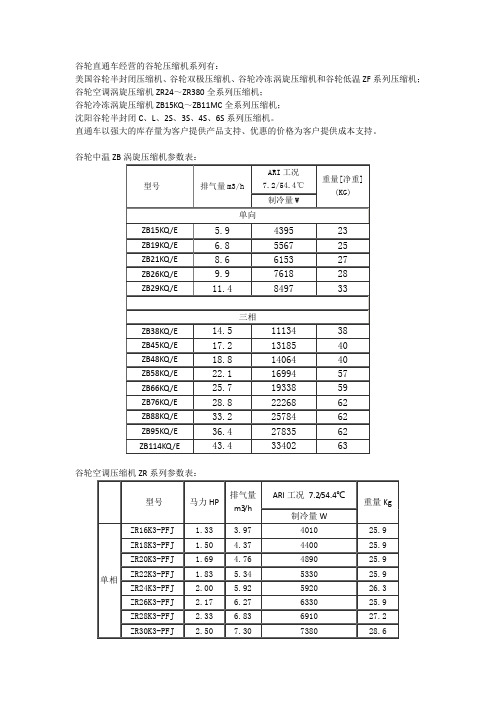
谷轮直通车经营的谷轮压缩机系列有:美国谷轮半封闭压缩机、谷轮双极压缩机、谷轮冷冻涡旋压缩机和谷轮低温ZF系列压缩机;谷轮空调涡旋压缩机ZR24~ZR380全系列压缩机;谷轮冷冻涡旋压缩机ZB15KQ~ZB11MC全系列压缩机;沈阳谷轮半封闭C、L、2S、3S、4S、6S系列压缩机。
直通车以强大的库存量为客户提供产品支持、优惠的价格为客户提供成本支持。
谷轮中温ZB涡旋压缩机参数表:谷轮空调压缩机ZR系列参数表:谷轮ZF系列低温压缩机参数表:型号HP 冷凝温度℃制冷量(W)10℃5℃0℃-5℃-10℃-15℃ZF06K4E 2 35 6950 5940 5040 4240 3550 2880 45 5960 5100 4330 3650 3050 2480 55 4910 4180 3550 3000 2520 2060ZF09K4E 3 35 9530 8130 6910 5820 4870 4100 45 8170 6970 5920 5000 4180 3550 55 6720 5730 4870 4120 3440 2900ZF11K4E 3.5 35 11700 10100 8550 7220 6050 5080 45 10200 8670 7370 6220 5210 4370 55 8400 7160 6050 5100 4260 3590ZF13K4E 4 35 12800 11300 9810 8420 7100 6030 45 11700 10100 8610 7250 6010 5120 55 9850 8320 6950 5780 4770 4070ZF15K4E 5 35 16800 14400 12200 10300 8650 7290 45 14500 12400 10500 88400 7390 6260 55 11900 10100 8570 7200 6030 5080ZF18K4E 6 35 17000 14400 12200 10200 8550 7250 45 14700 12500 10500 8840 7390 6240 55 12000 10200 8610 7250 6050 5120型号马力HP缸数排气量m3/h外形尺寸mm长宽高净重KG谷轮柔性涡旋压缩机在多方面显示出了它独特的优越性,高能效比,低噪音,高可靠性,低的系统设计成本和运行成本。
谷轮ZW系列(中间补气涡旋)压缩机应用指南

AE4-1381May 2011ZW21 to ZW61KAE and ZW30 to ZW61KSECopeland Scroll® Water Heating CompressorsTABLE OF CONTENTSSection Page Section PageIntroduction (2)ZW**KA Application (2)ZW**KS ApplicationVapour Injection - Theory of Operation (2)Heat Exchanger and Expansion Device Sizing (3)Flash Tank Application (3)Intermediate Pressure and Vapour Injection Superheat (3)Application ConsiderationsHigh Pressure Cut-Out (4)Low Pressure Cut-Out (4)Discharge Temperature Protection (4)Discharge Temperature Control (4)Discharge Mufflers (4)Oil Dilution and Compressor Cooling (4)Electrical Considerations (5)Brazing and Vapour Injection Line (5)Low Ambient Cut-Out (5)Internal Pressure Relief Valve (5)Internal Temperature Protection (5)Quiet Shutdown (5)Discharge Check Valve (5)Motor Protector (5)Accumulators (5)Screens (6)Crankcase Heat-Single Phase (6)Crankcase Heat-Three Phase (6)Pump Down Cycle (6)Minimum Run Time (6)Reversing Valves (6)Oil Type (7)System Noise & Vibration (7)Single Phase Starting Characteristics (7)PTC Start Components (7)Electrical Connections (7)Deep Vacuum Operation (7)Shell Temperature (7)Suction & Discharge Fittings (7)Three Phase Scroll Compressors (8)Brief Power Interruptions ..........................................8Assembly Line ProceduresInstalling the Compressor (8)Assembly Line Brazing Procedure (8)Pressure Testing (8)Assembly Line System Charging Procedure (8)High Potential (AC Hipot) Testing (9)Unbrazing System Components (9)Service ProceduresCopeland Scroll Functional Check (9)Compressor Replacement After Motor Burn (10)Start Up of a New or Replacement Compressor (10)FiguresBrief Product Overview (11)ZW21KAE Envelope (R-134a) (11)ZWKAE Envelope (R-407C, Dew Point) (12)ZWKA Envelope (R-22) (12)ZWKS Envelope (R-22) (13)ZWKSE Envelope (R-407C, Dew Point) (13)Heat Pump with Vapour Injection – EXV Control (14)Heat Exchanger Schematic (14)Heat Pump with Flash Tank (15)Possible Flash Tank Configuration (15)Oil Dilution Chart (16)Crankcase Heater (17)Compressor Electrical Connection (17)Scroll Tube Brazing (17)How a Scroll Works (18)IntroductionThe ZW**KA and ZW**KS Copeland Scroll®compressors are designed for use in vapour compression heat pump water heating applications. Typical model numbers include ZW30KA-PFS and ZW61KSE-TFP. This bulletin addresses the specifics of water heating in the early part and deals with the common characteristics and general application guidelines for Copeland Scroll compressors in the later sections. Operating principles of the scroll compressor are described in Figure 15 at the end of this bulletin.As the drive for energy efficiency intensifies, water heating by fossil-fueled boilers and electric elements is being displaced by vapour compression heat pumps. Emerson Climate Technologies has developed two lines of special water heater compressors to meet the requirements of this demanding application. ZW**KA compressors are designed for lighter duty applications where the ambient temperature does not fall below 0°C and where lower water temperatures can be accepted as the ambient temperature falls. ZW**KS compressors are equipped with a vapour injection cycle which allows reliable operation in cold climates with significantly enhanced heating capacity, higher efficiency, and minimal requirement to reduce water outlet temperatures. Figure 1gives a brief product overview.Water heating is characterized by long operating hours at both high load and high compression ratios. Demand for hot water is at its highest when ambients are low and when conventional heat pump capacity falls off. On the positive side, the system refrigerant charge is usually small, so the risk to the compressor from dilution and flooded starts will usually be lower than in split type air-to-air heat pumps.Water heaters must operate in a wide range of ambient temperatures, and many systems will require some method of defrost. Some systems such as Direct Heating, Top Down Heating or Single Pass Heating operate at a constant water outlet temperature with variable water flow. Others such as Recirculation Heating, Cyclic Heating or Multipass Heating use constant water flow with the water outlet and inlet temperatures both rising slowly as the storage tank heats up. Both system types need to cope with reheating a tank where the hot water has been partially used, and reheating to the setpoint temperature is required. More complex systems deliver water at relatively low temperatures for under-floor heating circuits and are switched over to sanitary water heating a few times per day to provide higher temperature water for sanitary use. In addition, some countries have specific water temperature requirements for legionella control.ZW**KA ApplicationThe application envelopes for ZW**KA compressors are shown in Figures 2 - 4.Appropriate system hardware and control logic must be employed to ensure that the compressor is always operating within the envelope. Small short-term excursions outside the envelope are acceptable at the time of defrost when the load on the compressor is low. Operation with suction superheat of 5 -10K is generally acceptable except at an evaporating tem-perature above 100C when a minimum superheat of 10K is required.ZW**KS ApplicationThe ZW**KS* vapour-injected scroll compressors differ from ZW**KA models in many important details:• Addition of vapour injection• Significantly different application envelopes• Some differences in locked rotor amps (LRA), maximum continuous current (MCC), andmaximum operating current (MOC) – seenameplatesThe application envelopes for ZW**KS compressors are shown in Figures 5 and 6.Vapour Injection – Theory of Operation Operation with vapour injection increases the capacity of the outdoor coil and in turn the capacity and efficiency of the system – especially in low ambient temperatures. A typical schematic is shown in Figure 7. A heat exchanger is added to the liquid line and is used to cool the liquid being delivered to the heating expansion device. Part of the liquid refrigerant flow is flashed through an expansion valve on the evaporator side of the heat exchanger at an intermediate pressure and used to subcool the main flow of liquid to the main expansion device. Vapour from the liquid evaporating at intermediate pressure is fed to the vapour injection port on the ZW**KS compressor. This refrigerant is injected into the mid-compression cycle of the scroll compressor and compressed to discharge pressure. Heating capacity is increased, because low temperature liquid with lower specific enthalpy supplied to the outdoor coil increases the amount of heat that can be absorbed from the ambient air. Increased heat absorbed from the ambient increases the system condensing temperature and in turn the compressor power input. The increase in power inputalso contributes to the improvement in the overall heating capacity.Vapour Injection can be turned on and off by the addition of an optional solenoid valve on the vapour injection line on systems using a thermostatic expansion valve. Alternatively, an electronic expansion valve can be used to turn vapour injection on and off and to control the vapour injection superheat. A capillary tube is not suitable for controlling vapour injection.The major advantage of the electronic expansion valve is that it can be used to optimise the performance of the system and at the same time control the discharge temperature by injecting “wet vapour” at extreme operating conditions.The configurations and schematics shown are for reference only and are not applicable to every system. Please consult with your Emerson Application Engineer.Heat Exchanger and Expansion Device Sizing Various heat exchanger designs have been used successfully as subcoolers. In general they should be sized so that the liquid outlet temperature is less than 5K above the saturated injection temperature at the customer low temperature rating point. At very high ambient temperatures, it will normally be beneficial to turn vapour injection off to limit the load on the compressor motor. Application Engineering Bulletin AE4-1327 and Emerson Climate Technologies Product Selection Software can be used to help size the subcooling heat exchanger and thermal expansion valves, but selection and proper operation must be checked during development testing. Plate type subcoolers must be installed vertically with the injection expansion device connected at the bottom through a straight tube at least 150mm long to ensure good liquid distribution. See the schematic in Figure 8. Flash Tank ApplicationA possible flash tank configuration is shown in Figure9. This particular configuration is arranged to have flow through the flash tank and expansion devices in heating, and it bypasses the tank in defrost mode. The flash tank system works by taking liquid from the condenser and metering it into a vessel through a high-to-medium pressure expansion device. Part of the liquid boils off and is directed to the compressor vapour injection port. This refrigerant is injected into the mid-compression cycle of the scroll compressor and compressed to discharge pressure. The remaining liquid is cooled, exits from the bottom of the tank at intermediate pressure, and flows to the medium-to-low pressure expansion device which feeds the outdoor coil. Low temperature liquid with lower specific enthalpy increases the capacity of the evaporator without increasing mass flow and system pressure drops.Recommended tank sizing for single compressor application in this size range is a minimum of 200 mm high by 75 mm in diameter with 3/8 in. (9.5mm) tubing connections, although it is possible to use a larger tank to combine the liquid/vapour separation and receiver functions in one vessel. A sight tube (liquid level gauge) should be added to the tank for observation of liquid levels during lab testing. See schematic diagram Figure 10 for clarification.It is important to maintain a visible liquid refrigerant level in the tank under all operating conditions. Ideally the liquid level should be maintained in the 1/3 to 2/3 full range.Under no circumstances should the level drop to empty or rise to a full tank. As the tank level rises, liquid droplets tend to be swept into the vapour line leading to “wet” vapour injection. Although this can be useful for cooling a hot compressor, the liquid quantity cannot be easily controlled. Compressor damage is possible if the tank overflows. If liquid injection is required for any reason, it can be arranged as shown in Figures 7 and 9.Since liquid leaves the tank in a saturated state, any pressure drop or temperature rise in the line to the medium-to-low pressure expansion device will lead to bubble formation. Design or selection of the medium-to-low pressure expansion device requires careful attention due to the possible presence of bubbles at the inlet and the low pressure difference available to drive the liquid into the evaporator. An electronic expansion valve is the preferred choice. Intermediate Pressure and Vapour Injection SuperheatPressure in the flash tank cannot be set and is a complex function of the compressor inlet condition and liquid condition at the inlet of the high-to-medium pressure expansion device. However, liquid level can be adjusted, which in turn will vary the amount of liquid subcooling in the condenser (water to refrigerant heat exchanger) and vary the injection pressure. Systems with low condenser subcooling will derive the biggest gains by the addition of vapour injection. Systems operating with high pressure ratios will show the largest gains when vapour injection is applied. Such systems will have higher vapour pressure and higher injectionmass flow. Intermediate pressures in flash tank and heat exchanger systems should be very similar unless the subcooling heat exchanger is undersized and there is a large temperature difference between the evaporator and the liquid sides. Vapour exiting a flash tank will be saturated and may pick up 1 - 2K superheat in the vapour line to the compressor. Vapour injection superheat cannot be adjusted on flash tank systems. Heat exchanger systems will be at their most efficient when the vapour injection superheat is maintained at approximately 5K.APPLICATION CONSIDERATIONSHigh Pressure Cut OutIf a high pressure control is used with these compressors, the recommended maximum cut out settings are listed in Figure 1. The high pressure control should have a manual reset feature for the highest level of system protection. It is not recommended to use the compressor to test the high pressure switch function during the assembly line test.Although R-407C runs with higher discharge pressure than R-22, a common setting can be used. The cutout settings for R-134a are much lower, and the switches must be selected or adjusted accordingly.Low Pressure Cut OutA low pressure cut out is an effective protection against loss of charge or partial blockage in the system. The cut out should not be set more than 3 - 5K equivalent suction pressure below the lowest operating point in the application envelope. Nuisance trips during defrost can be avoided by ignoring the switch until defrost is finished or by locating it in the line between the evaporator outlet and the reversing valve. This line will be at discharge pressure during defrost. Recommended settings are given in Figure 1. Discharge Temperature ProtectionAlthough ZW compressors have an internal bi-metal Therm-O-Disc®(TOD) on the muffler plate, external discharge temperature protection is recommended for a higher level of protection and to enable monitoring and control of vapour injection on ZW**KS* models. The protection system should shut down the compressor when the discharge line temperature reaches 125°C. In low ambient operation, the temperature difference between the scroll center and the discharge line is significantly increased, so protection at a lower discharge temperature, e.g. 120°C when the ambient is below 0°C, will enhance system safety. For the highest level of system protection, the discharge temperature control should have a manual reset feature. The discharge sensor needs to be well insulated to ensure that the line temperature is accurately read. The insulation material must not deteriorate over the expected life of the unit.Discharge Temperature ControlSome systems use an electronic expansion valve to control the vapour injection superheat and a thermistor to monitor the discharge temperature. This combination allows the system designer to inject a small quantity of liquid to keep the discharge temperature within safe limits and avoid an unnecessary trip. Liquid injection should begin at approximately 115°C and should be discontinued when the temperature falls to 105°C. Correct functioning of this system should be verified during system development. It is far preferable to use liquid injection into the vapour injection port to keep the compressor cool rather than inject liquid into the compressor suction which runs the risk of diluting the oil and washing the oil from the moving parts. If some operation mode requires liquid injection but without the added capacity associated with “wet” vapour injection, a liquid injection bypass circuit can be arranged as shown in Figures 7 and 9.Caution: Although the discharge and oil temperature are within acceptable limits, the suction and discharge pressures cannot be ignored and must also fall within the approved application envelope.Discharge MufflersDischarge mufflers are not normally required in water heaters since the refrigerant does not circulate within the occupied space.Oil Dilution and Compressor CoolingThe oil temperature diagram shown in Figure 11is commonly used to make a judgment about acceptable levels of floodback in heat pump operation. Systems operating with oil temperatures near the lower limit line are never at their most efficient. Low ambient heating capacity and efficiency will both be higher if floodback is eliminated and the system runs with 1 - 5K suction superheat. Discharge temperature can be controlled by vapour injection, “wet” vapour injection, or even liquid injection if necessary. In this situation, the oil temperature will rise well into the safe zone, and the compressor will not be at risk of failure from diluted oil. The oil circulation rate will also be reduced as crankcase foaming disappears. Special care needs to be taken at the end of defrost to ensure that the compressor oil is not unacceptably diluted. The system will resume heating very quickly and bearing loads willincrease accordingly, so proper lubrication must be ensured.Electrical ConsiderationsMotor configuration and protection are similar to those of standard Copeland Scroll compressors. In some cases, a larger motor is required in the ZW**KS* models to handle the load imposed by operating with vapour injection. Wiring and fuse sizes should be reviewed accordingly.Brazing the Vapour Injection LineThe vapour injection connection is made from copper coated steel, and the techniques used for brazing the suction and discharge fittings apply to this fitting also. Low Ambient Cut-OutA low ambient cut-out is not required to limit heat pump operation with ZW**KS compressors. Water heaters using ZW**KA compressors must not be allowed to run in low ambients since this configuration would run outside of the approved operating envelope causing overheating or excessive wear. A low ambient cut-out should be set at 0°C for ZW**KA modelsIn common with many Copeland Scroll compressors, ZW models include the features described below: Internal Pressure Relief (IPR) ValveAll ZW compressors contain an internal pressure relief valve that is located between the high side and the low side of the compressor. It is designed to open when the discharge-to-suction differential pressure exceeds 26 - 32 bar. When the valve opens, hot discharge gas is routed back into the area of the motor protector to cause a trip.Internal Temperature ProtectionThe Therm-O-Disc® or TOD is a temperature-sensitive snap disc device located on the muffler plate between the high and low pressure sides of the compressor. It is designed to open and route excessively hot discharge gas back to the motor protector. During a situation such as loss of charge, the compressor will be protected for some time while it trips the protector. However, as refrigerant leaks out, the mass flow and the amperage draw are reduced and the scrolls will start to overheat.A low pressure control is recommended for loss of charge protection in heat pumps for the highest level of system protection. A cut out setting no lower than 2.5 bar for ZW**KA* models and 0.5 bar for ZW**KS* models is recommended. The low pressure cut-out, if installed in the suction line to the compressor, can provide additional protection against an expansion device failed in the closed position, a closed liquid line or suction line service valve, or a blocked liquid line screen, filter, orifice, or TXV. All of these can starve the compressor for refrigerant and result in compressor failure. The low pressure cut-out should have a manual reset feature for the highest level of system protection. If a compressor is allowed to cycle after a fault is detected, there is a high probability that the compressor will be damaged and the system contaminated with debris from the failed compressor and decomposed oil.If current monitoring to the compressor is available, the system controller can take advantage of the compressor TOD and internal protector operation. The controller can lock out the compressor if current draw is not coincident with the contactor energizing, implying that the compressor has shut off on its internal protector. This will prevent unnecessary compressor cycling on a fault condition until corrective action can be taken.Quiet Shut downAll scrolls in this size range have a fast acting valve in the center of the fixed scroll which provides a very quiet shutdown solution. Pressure will equalize internally very rapidly and a time delay is not required for any of the ZW compressors to restart. Also refer to the section on “Brief Power Interruption”. Discharge Check ValveA low mass, disc-type check valve in the discharge fitting of the compressor prevents the high side, high pressure discharge gas from flowing rapidly back through the compressor. This check valve was not designed to be used with recycling pump down because it is not entirely leak-proof.Motor ProtectorConventional internal line break motor protection is provided. The protector opens the common connection of a single-phase motor and the center of the Y connection on three-phase motors. The three-phase protector provides primary single-phase protection. Both types of protectors react to current and motor winding temperature.AccumulatorsThe use of accumulators is very dependent on the application. The scroll’s inherent ability to handle liquid refrigerant during occasional operating flood back situations often makes the use of an accumulator unnecessary in many designs. If flood back is excessive, it can dilute the oil to such an extent thatbearings are inadequately lubricated, and wear will occur. In such a case, an accumulator must be used to reduce flood back to a safe level that the compressor can handle.In water heaters, floodback is likely to occur when the outdoor coil frosts. The defrost test must be done at an outdoor ambient temperature of around 0°C in a high humidity environment. Liquid floodback must be monitored during reversing valve operation, especially when coming out of defrost. Excessive floodback occurs when the sump temperature drops below the safe operation line shown in Figure 11 for more than 10 seconds.If an accumulator is required, the oil return orifice should be 1 - 1.5mm in diameter depending on compressor size and compressor flood back results. Final oil return hole size should be determined through testing. ScreensScreens with a mesh size finer than 30 x 30 (0.6mm openings) should not be used anywhere in the system with these compressors. Field experience has shown that finer mesh screens used to protect thermal expansion valves, capillary tubes, or accumulators can become temporarily or permanently plugged with normal system debris and block the flow of either oil or refrigerant to the compressor. Such blockage can result in compressor failure.Crankcase Heater - Single PhaseCrankcase heaters are not required on single phase compressors when the system charge is not over 120% of the limit shown in Figure 1. A crankcase heater is required for systems containing more than 120% of the compressor refrigerant charge limit listed in Figure 1. This includes long line length systems where the extra charge will increase the standard factory charge above the 120% limit.Experience has shown that compressors may fill with liquid refrigerant under certain circumstances and system configurations, notably after longer off cycles when the compressor has cooled. This may cause excessive start-up clearing noise, or the compressor may lock up and trip on the protector several times before starting. The addition of a crankcase heater will reduce customer noise and light dimming complaints since the compressor will no longer have to clear out liquid during startup. Figure 12lists the crankcase heaters recommended for the various models and voltages.Crankcase Heat – Three-PhaseA crankcase heater is required for three-phase compressors when the system charge exceeds the compressor charge limit listed in Figure 1and an accumulator cannot be piped to provide free liquid drainage during the off cycle.Pump Down CycleA pump down cycle for control of refrigerant migration is not recommended for scroll compressors of this size. If a pump down cycle is used, a separate external check valve must be added.The scroll discharge check valve is designed to stop extended reverse rotation and prevent high-pressure gas from leaking rapidly into the low side after shut off. The check valve will in some cases leak more than reciprocating compressor discharge reeds, normally used with pump down, causing the scroll compressor to cycle more frequently. Repeated short-cycling of this nature can result in a low oil situation and consequent damage to the compressor. The low-pressure control differential has to be reviewed since a relatively large volume of gas will re-expand from the high side of the compressor into the low side on shut down. Minimum Run TimeThere is no set answer to how often scroll compressors can be started and stopped in an hour, since it is highly dependent on system configuration. Other than the considerations in the section on Brief Power Interruptions, there is no minimum off time. This is because scroll compressors start unloaded, even if the system has unbalanced pressures. The most critical consideration is the minimum run time required to return oil to the compressor after startup.Since water heaters are generally of compact construction, oil return and short cycling issues are rare. Oil return should not be a problem unless the accumulator oil hole is blocked.Reversing ValvesSince Copeland Scroll compressors have very high volumetric efficiency, their displacements are lower than those of comparable capacity reciprocating compressors. As a result, Emerson recommends that the capacity rating on reversing valves be no more than 2 times the nominal capacity of the compressor with which it will be used in order to ensure proper operation of the reversing valve under all operating conditions.The reversing valve solenoid should be wired so that the valve does not reverse when the system isshut off by the operating thermostat in the heating or cooling mode. If the valve is allowed to reverse at system shutoff, suction and discharge pressures are reversed to the compressor. This results in pressures equalizing through the compressor which can cause the compressor to slowly rotate until the pressures equalize. This condition does not affect compressor durability but can cause unexpected sound after the compressor is turned off.Oil TypeThe ZW**K* compressors are originally charged with mineral oil. A standard 3GS oil may be used if the addition of oil in the field is required. See the compressor nameplate for original oil charge. A complete recharge should be ~100 ml less than the nameplate value.ZW**K*E are charged with POE oil. Copeland 3MAF or Ultra 22 CC should be used if additional oil is needed in the field. Mobil Arctic EAL22CC, Emkarate RL22, Emkarate 32CF and Emkarate 3MAF are acceptable alternatives. POE oil is highly hygroscopic, and the oil should not be exposed to the atmosphere except for the very short period required to make the brazing connections to the compressor.System Noise and VibrationCopeland Scroll compressors inherently have low sound and vibration characteristics, but the characteristics differ in some respects from those of reciprocating or rotary compressors. The scroll compressor makes both a rocking and a torsional motion, and enough flexibility must be provided to prevent vibration transmission into any lines attached to the unit. This is usually achieved by having tubing runs at least 30cm long parallel to the compressor crankshaft and close to the shell. ZW compressors are delivered with rubber grommets to reduce vibration transmission to the system baseplate.Single Phase Starting CharacteristicsStart assist devices are usually not required, even if a system utilizes non-bleed expansion valves. Due to the inherent design of the Copeland Scroll, the internal compression components always start unloaded even if system pressures are not balanced. In addition, since internal compressor pressures are always balanced at startup, low voltage starting characteristics are excellent for Copeland Scroll compressors. Starting current on any compressor may result in a significant “sag” in voltage where a poor power supply is encountered. The low starting voltage reduces the starting torque of the compressor and subsequently increases the start time. This could cause light dimming or a buzzing noise where wire is pulled through conduit. If required, a start capacitor and potential relay can be added to the electrical circuit. This will substantially reduce start time and consequently the magnitude and duration of both light dimming and conduit buzzing.PTC Start ComponentsFor less severe voltage drops or as a start boost, solid state Positive Temperature Coefficient devices rated from 10 to 25 ohms may be used to facilitate starting for any of these compressors.Electrical ConnectionThe orientation of the electrical connections on the Copeland Scroll compressors is shown in Figure 13 and is also shown on the wiring diagram on the top of the terminal box cover.Deep Vacuum OperationScrolls incorporate internal low vacuum protection and will stop pumping (unload) when the pressure ratio exceeds approximately 10:1. There is an audible increase in sound when the scrolls start unloading. This feature does not prevent overheating and destruction of the scrolls, but it does protect the power terminals from internal arcing.Copeland Scroll compressors(as with any refrigerant compressor) should never be used to evacuate a refrigeration or air conditioning system. The scroll compressor can be used to pump down refrigerant in a unit as long as the pressures remain within the operating envelope. Prolonged operation at low suction pressures will result in overheating of the scrolls and permanent damage to the scroll tips, drive bearings and internal seal. (See AE24-1105 for proper system evacuation procedures.)Shell TemperatureCertain types of system failures, such as condenser or evaporator blockage or loss of charge, may cause the top shell and discharge line to briefly but repeatedly reach temperatures above 175ºC as the compressor cycles on its internal protection devices. Care must be taken to ensure that wiring or other materials, which could be damaged by these temperatures, do not come in contact with these potentially hot areas. Suction and Discharge FittingsCopeland Scroll compressors have copper plated steel suction and discharge fittings. These fittings are far more rugged and less prone to leaks than。
美国艾默生公司压缩机应用技术讲座第22讲 谷轮(低温强热)涡旋在热泵式空调器中的应用(2)
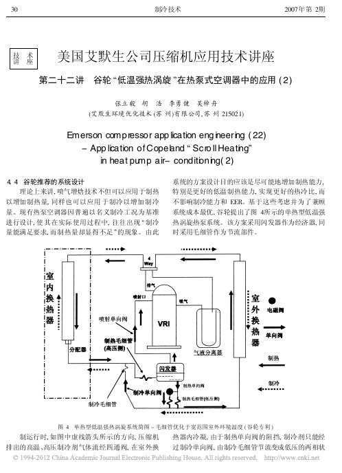
显示出非常好的压缩机可靠性能: 在整个制热 季节中均保持着合适的油槽温度 , 系统没有过量回液 的现象。并且排气温度均不超过 80 , 相当安全。
图 5 普通涡旋和低温强热涡旋的制热量对比
32
制冷技术 该型号机组于 2005 年冬季开始长期运行于沈阳
2007 年第 2期
得的功耗值相当吻合。从图 6 中 24 小时的测试记录 里可发现 , 当环境温度最低为 - 22 时, 房间温度依 然能维持在 20 以上。沈阳 现场的运行测试, 其目 的主要为了考核机组及压缩机在极端温度条件下的 可靠性。该机组完成现场测试后的进行了系统复测 和部件解剖分析, 其可靠性得到充分证实。
两位日本专家在上海市制冷学会作专题报告
本刊讯 应上海市制冷学会空调热泵专业委 员会邀请, 日本建筑设备设计研究所顾问大窪道知和 日本节能中心专家植山哲平于 2007年 6 月 6 日下午 在上海市科学会堂作专题报告。 专题报告会由上海市制冷学会理事、 同济大学范 存养教授主持。 大 窪道知在 地球环境问题 专题报告中以详实 的数据和生动的图表揭示由于世界人口持续膨胀、 人 类活动造成能源大量消耗 , 招致矿石燃料的枯竭、 空 气中 CO 2 浓度不断上升、 世界平均气温上升、 异常天 气的常态化等一连串环境问题。大窪道知在此基础 上介绍了日本政府的对策 , 从新能源的开发研究到空 调、 制冷的新设备和节能措施。 植山哲平在 冰蓄冷技术介绍 专题报告中介绍 了冰蓄冷时间率融解特性 , 有效蓄冷容量。特别详细 阐述了冰蓄冷万能计算方法, 这 种计算方法简单 明 了 , 可以节省不少方案设计时间 , 植山哲平同时介绍 了许多日本冰蓄冷应用实例。 大窪道知在 东京大规模建筑事例介绍 的专题 报告中, 介绍了日本东京近期竣工的一个区域建筑物 的空调设置情况, 这个区域有 7 万 m , 区域内有办公 楼、 商场、 宾馆酒店、 住宅和文化娱乐设施。这些建筑 物设计时 共同的基 本方针为 : ( 1) 使建筑 物具有魅 力 , 确保建筑物可靠性 , 内部设施变更的方便; ( 2) 考 虑对环境的影响, 追求经济性; ( 3) 追求能源效率 , 配 置的空调设备的最小化 ; ( 4) 经济管理简单方便; ( 5) 考虑在灾害时的安全设施。大窪道知按建筑物不同 用途予以分别介绍 , 特别强调在空调设备设置时一定 要留有余地, 以便客户进驻后根据需要可以增减空调 机组, 来适应各种使用工况。 两位日本专家精彩、 务实的报告受到上海暖通空 调行业精英们热烈欢迎 , 日本专家在报告后还回答了 与会者的提问。
谷轮涡旋压缩机_ZB_ZF
29000 25500
7790 9630
-5
17700 16100 14150 3920 4880 6100 20100 18400 16500 4360 5400 6750 23800 21700 19500 5100 6350 8000 27400 24900 22000 5750 7200 9050 29300 26500 22400 6590 8180 10100 35400 31700 27000 7920 9710 12050
2050 2550
8150 7300 6250 2490 3100 3880 10350 9400 8200 3160 3880 4810 11485 10390 9134 3246 4080 5116
* 最低蒸发温度保持-12℃
* 测试条件:回气温度20℃,过冷度0℃
*
最大吸气过热度为11K
-10
排气
动涡旋
径向柔性
轴 吸气
向 柔 性
高能效比 涡旋盘磨合而不是磨损 *随运行时间的增加表现更好 *容积效率高
更低的噪音和振动水平
平滑的声音频谱和柔和的声音质量
*压缩腔永远是对称分布 *很低的不平衡应力
*高精度的制造工艺
*无需振动吸收装置
卸载启动技术 压缩部件在停机后互相分开压缩机内部全面的压力平 衡,无需附加启动装置。
-5
4800 4350 3750 1090 1420 1840 5300 4850 4350 1250 1590 2000 6800 6200 5500 1620 2010 2500 7450 6800 6050 1750 2210 2780 9140 8290 7370 2070 2570 3190 11000 9950 8800 2540 3150 3900 13550 12400 11100 3170 3870 4780 15042 13700 12194 3312 4141 51822ຫໍສະໝຸດ 510HP
2011版华安达谷轮R410A涡旋压缩机样本

R410A Scroll Compressor For Air ConditioningR410A 空 调 涡 旋 压 缩 机NEW低运行成本可靠环保宁静高效high efficiencylow noiseenvironment protectionhigh reliabilitylow operation cost目 录压缩机特性及运行范围.................................2产品型谱图................................................3技术参数...................................................4性能参数...................................................5注油量......................................................11电气参数...................................................12压缩机接线图.............................................13外形尺寸图................................................15压缩机配置................................................23应用小常识................................................24应用注意事项.............................................27命名规则 (29)ZP/VP系列柔性涡旋压缩机特性及运行范围7060ZP系列柔性涡旋(ZP57-ZP485)基于优越的谷轮涡旋技术平台,特别为高效系统优化。
谷轮压缩机参数表
谷轮直通车经营的谷轮压缩机系列有:
美国谷轮半封闭压缩机、谷轮双极压缩机、谷轮冷冻涡旋压缩机和谷轮低温ZF系列压缩机;谷轮空调涡旋压缩机ZR24~ZR380全系列压缩机;
谷轮冷冻涡旋压缩机ZB15KQ~ZB11MC全系列压缩机;
沈阳谷轮半封闭C、L、2S、3S、4S、6S系列压缩机。
直通车以强大的库存量为客户提供产品支持、优惠的价格为客户提供成本支持。
谷轮中温ZB涡旋压缩机参数表:
谷轮空调压缩机ZR系列参数表:
谷轮ZF系列低温压缩机参数表:
谷轮半封闭压缩机C系列参数表:
谷轮柔性涡旋压缩机在多方面显示出了它独特的优越性,高能效比,低噪音,高可靠性,低的系统设计成本和运行成本。
谷轮的革命性技术已为世界各地的制造商,分销商和最终用户所采用。
到今天为止,谷轮有超过四千万台柔性涡旋压缩机服务于人类日常生活和科学研究等各个领域。
谷轮公司在开发空调柔性涡旋压缩机的同时,也在全力研发冷冻涡旋压缩机;涡旋在空调行业的成功应用,预示着冷冻的未来属于涡旋。
艾默生谷轮低温涡旋ZF样本

谷轮涡旋™ZFKQ冷冻压缩机目录我们的愿景:艾默生环境优化技术将与我们的合作伙伴一起,向世界范围的客户提供整合的环境优化解决方案, 提高人类生活舒适度,保障食品安全, 保护环境。
领先技术造就一流产品艾默生环境优化技术公司是世界领先的家用及工商业应用领域制冷、空调及采暖解决方案提供商,并以其先进技术为行业提供技术支持和培训服务。
从20世纪40年代的第一台半封闭压缩机, 50年代的封闭式压缩机, 80,90年代高能效碟阀半封闭压缩机, 空调和制热涡旋压缩机, 到最新的Stream 半封闭压缩机和数码涡旋压缩机, 艾默生环境优化技术在过去的80年中不断地向市场推出新技术新产品。
艾默生环境优化技术作为制冷、空调及采暖行业的解决方案提供商, 其Copeland™ (谷轮™)压缩机产品能够满足市场的不同需求, 涡旋及半封闭压缩机可用于所有市场主流制冷剂, 配备智能电子控制模块,带领压缩机技术走向新高度。
特点及优势艾默生环境优化技术研发的谷轮涡旋ZFKQ 系列压缩机为低环境温度下的应用提供优异的运行性能。
此系列压缩机具有宽广运行范围,蒸发温度从-40°C 到+7°C 。
优化设计使其完美地适用于食品冷冻; 同时,涡旋盘的柔性设计使压缩机具有优秀的承受液击能力。
产品范围包括:• ZF*KQ/E 型号采用喷液技术控制排气温度,扩展压缩机运行范围。
• ZFI*KQ/E 型号采用喷气技术及过冷器,提高系统制冷能力及效率。
全年保持高能效• 作为艾默生环境优化技术专利的谷轮柔性涡旋TM 压缩机技术, 依靠离心力使涡旋盘互相啮合, 可以在保证最高效的 运行条件下使气体泄漏最小。
• 谷轮涡旋TM 压缩机可以在最低4.4°C 冷凝温度的低温环境下运行, 可以提供最高的季节能效比。
• 压缩机上自带安装的动态排气阀可根据要求调整压缩机排气压力, 防止压缩机内气体的再压缩, 在高压比的情况下 可观的提高能效。
谷轮ZR全封闭涡旋压缩机技术参数精编手册
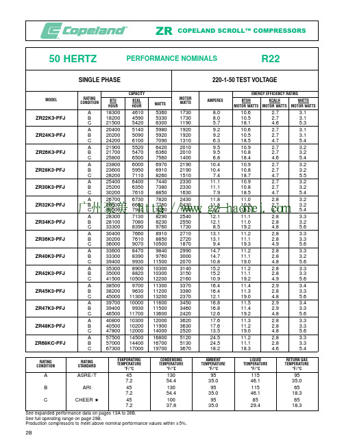
PERFORMANCE NOMINALS50 HERTZR22SINGLE PHASE220-1-50 TEST VOLTAGECAPACITYENERGY EFFICIENCY RATINGRATING MOTOR MODELAMPERESBTU KCAL BTUH KCALH WATTS CONDITIONWATTSWATTSHOURHOURMOTOR WATTS MOTOR WATTSMOTOR WATTSA 183004610536017308.010.6 2.7 3.1ZR22K3-PFJB 182004590533017308.010.5 2.7 3.1C 21500542063001190 5.718.1 4.6 5.3A 204005140598019209.210.6 2.7 3.1ZR24K3-PFJ B 202005090592019209.210.5 2.7 3.1C 24200610070901310 6.318.5 4.7 5.4A 219005520642020109.510.9 2.7 3.2ZR26K3-PFJ B 217005470636020109.510.8 2.7 3.2C 25800650075601400 6.818.4 4.6 5.4A 2380060006970219010.410.9 2.7 3.2ZR28K3-PFJ B 2360059506910219010.410.8 2.7 3.2C 282007110826015107.418.7 4.7 5.5A 2540064007440233011.110.9 2.7 3.2ZR30K3-PFJ B 2520063507380233011.110.8 2.7 3.2C 302007610885016307.918.5 4.7 5.4A 2670067307820243011.811.0 2.8 3.2ZR32K3-PFJ B 2650066807760243011.810.9 2.7 3.2C 315007940923017008.718.5 4.7 5.4A 2830071308290254012.111.1 2.8 3.3ZR34K3-PFJ B 2810070808230255012.111.0 2.8 3.2C 333008390976017308.519.2 4.8 5.6A 3040076608910271013.111.2 2.8 3.3ZR36K3-PFJ B 3020076108850272013.111.1 2.8 3.3C 3600090701050018709.419.3 4.9 5.6A 3360084709840299014.711.2 2.8 3.3ZR40K3-PFJ B 3330083909760300014.711.1 2.8 3.2C 39400993011500207010.819.0 4.8 5.6A 35300890010300314015.211.2 2.8 3.3ZR42K3-PFJ B 35000882010300315015.211.1 2.8 3.3C 415001050012200216010.919.2 4.9 5.6A 38500970011300337016.411.4 2.9 3.4ZR45K3-PFJ B 38200963011200338016.411.3 2.8 3.3C 450001130013200237012.119.0 4.8 5.6A 397001000011600345016.811.5 2.9 3.4ZR47K3-PFJ B 39400993011500346016.811.4 2.9 3.3C 465001170013600242012.619.2 4.8 5.6A 408001030012000362017.611.3 2.8 3.3ZR48K3-PFJ B 405001020011900363017.611.2 2.8 3.3C 478001200014000252013.519.0 4.8 5.6A 575001450016800512024.511.2 2.8 3.3ZR68KC-PFJB 570001440016700513024.511.1 2.8 3.3C 673001700019700367018.218.3 4.6 5.4广州豪美 http://www.gz-haomei.comPERFORMANCE NOMINALS50 HERTZR22THREE PHASETEST VOLTAGECAPACITYENERGY EFFICIENCY RATINGRATING MOTOR MODELAMPERES*BTU KCAL BTUH KCALH WATTS CONDITIONWATTSWATTSHOURHOURMOTOR WATTS MOTOR WATTSMOTOR WATTSA 18300461053601770 5.5/3.210.3 2.6 3.0ZR22K3-TF5/DB 18200459053301770 5.5/3.210.3 2.6 3.0C 21500542063001170 4.3/2.518.4 4.6 5.4A 204005140598019206.0/3.510.6 2.7 3.1ZR24K3-TF5/DB 20200509059201920 6.0/3.510.5 2.7 3.1C 24200610070901250 4.7/2.719.4 4.9 5.7A 21900552064202010 6.6/3.810.9 2.7 3.2ZR26K3-TF5/DB 21700547063602010 6.6/3.810.8 2.7 3.2C 25800650075601360 5.0/2.919.0 4.8 5.6A 23800600069702150 6.9/4.011.1 2.8 3.2ZR28K3-TF5/DB 23600595069102150 6.9/4.011.0 2.8 3.2C 28200711082601450 5.4/3.119.4 4.9 5.7A 254006400744022907.3/4.211.1 2.8 3.2ZR30K3-TF5/DB 252006350738022907.3/4.211.0 2.8 3.2C 30200761088501540 5.5/3.219.6 4.9 5.7A 267006730782024307.6/4.411.0 2.8 3.2ZR32K3-TF5/DB 265006680776024307.6/4.410.9 2.7 3.2C 31500794092301640 5.9/3.419.2 4.8 5.6A 283007130829025007.9/4.611.3 2.9 3.3ZR34K3-TF5/DB 281007080823025007.9/4.611.2 2.8 3.3C 33400842097901700 6.2/3.619.6 5.0 5.8A 304007660891026908.3/4.811.3 2.8 3.3ZR36K3-TF5/DB 302007610885027008.3/4.811.2 2.8 3.3C 360009070105001810 6.4/3.719.9 5.0 5.8A 336008470984029609.2/5.311.4 2.9 3.3ZR40K3-TF5/DB 333008390976029709.2/5.311.2 2.8 3.3C 3940099301150019907.1/4.119.8 5.0 5.8A 3530089001030031009.5/5.511.4 2.9 3.3ZR42K3-TF5/DB 3500088201030031109.5/5.511.3 2.8 3.3C41500105001220020807.4/4.320.05.05.9*Ampere values shown are at 220 volts/380 volts.220-3-50 (TF5)380-3-50 (TFD)广州豪美 http://www.gz-haomei.comPERFORMANCE NOMINALS50 HERTZR22THREE PHASETEST VOLTAGECAPACITYENERGY EFFICIENCY RATINGRATING MOTOR MODELAMPERES*BTU KCAL BTUH KCALH WATTS CONDITIONWATTSWATTSHOURHOURMOTOR WATTS MOTOR WATTSMOTOR WATTSA 38200963011200331010.5/6.111.5 2.9 3.4ZR45KC-TF5/DB 37900955011100332010.5/6.111.4 2.9 3.3C 44500112001300022908.3/4.819.4 4.9 5.7A 397001000011600342010.9/6.311.6 2.9 3.4ZR47KC-TF5/DB 39400993011500343010.9/6.311.5 2.9 3.4C 46300117001360023408.8/5.119.8 5.0 5.8A 408001030012000360011.2/6.511.3 2.9 3.3ZR48KC-TF5/DB 405001020011900361011.2/6.511.2 2.8 3.3C 47800120001400024908.6/5.019.2 4.8 5.6A 454001140013300397012.6/7.311.4 2.9 3.4ZR54KC-TF5/DB 450001130013200398012.6/7.311.3 2.8 3.3C 530001340015500282010.0/5.818.8 4.8 5.5A 479001210014000416013.5/7.811.5 2.9 3.4ZR57KC-TF5/DB 475001200013900417013.5/7.811.4 2.9 3.3C 560001410016400295010.4/6.019.0 4.8 5.6A 514001300015100442014.0/8.111.6 2.9 3.4ZR61KC-TF5/DB 510001290014900443014.0/8.111.5 2.9 3.4C 600001510017600317011.1/6.418.9 4.8 5.6A 580001460017000495014.9/8.611.7 2.9 3.4ZR68KC-TF5/DB 575001450016800496014.9/8.611.6 2.9 3.4C 680001710019900343011.4/6.619.8 5.0 5.8A 610001540017900517015.4/8.911.8 3.0 3.5ZR72KC-TF5/DB 605001520017700518015.4/8.911.7 2.9 3.4C 715001800020900361011.6/6.719.8 5.0 5.8A 685001730020100580018.1/10.511.8 3.0 3.5ZR81KC-TF5/DB 680001710019900581018.1/10.511.7 2.9 3.4C795002000023300414015.2/8.819.24.85.6*Ampere values shown are at 220 volts/380 volts.220-3-50 (TF5)380-3-50 (TFD)广州豪美 http://www.gz-haomei.comAPPLICATION NOTES•The Copeland Scroll Compressor has been under developmentat Copeland since 1979 and is the most efficient and durable compressor we have ever developed for residential air condi-tioning and heat pump applications.Copeland Scroll compres-sors have fewer moving parts and no dynamic suction or dis-charge valves.In addition, they offer very low vibration and sound levels and are very tolerant to stresses caused by liquid slugging, flooded starts, and debris commonly found in resi-dential split air conditioning and heat pump systems.•These Copeland Scrolls include a higher range of capacities and more electrical options than the earlier ZR1 models.Inaddition, there are several operating characteristics and design features which are different from the ZR1 models.•The Copeland Scroll is a new type of compressor and there are a number of application characteristics which are different from the traditional reciprocating compressor.These are fully detailed in the Application Bulletin AE4-1312.•The motor protector used in these ZR compressors is mounted internally and its proven design is the result of extensive labo-ratory research and field testing.It protects the motor from maximum operating overload, both high and low voltage, and loss of refrigerant charge.It is both current and heat sensing.The single phase protector protects both the run and start windings.The three phase protector is wired at the connection point of the motor's three legs.Therefore, the protector protects all three legs and if a problem occurs with one or more of them,the protector breaks all three phases.•The rotational speed of the compressor is:•50 Hertz 2900 RPM•No crankcase heater is required for single phase compressors.•A crankcase heater is required for three phase compressors when the system charge exceeds the compressor refrigerant charge limit shown below, and no accumulator is used, or when the charge exceeds this limit and an accumulator cannot be piped to provide free liquid drainage into the accumulator dur-ing the off cycle.•ZR22 to ZR488 pounds (3.6 Kg)••Since Copeland Scroll Compressors have very high volumetricefficiency, their displacements are lower than for comparable capacity reciprocating compressors.As a result, Copeland mends that the capacity rating on reversing valves be no more than 1.5 to 2 times the nominal capacity of the compres-sor with which it will be used in order to ensure proper opera-tion of the reversing valve under all operating conditions.•The compressor has the approval to operate as a heat pump within the operating range.Its increased bearing surfaces and improved lubrication system provide excellent reliability even when operated at the heat pump's higher compression ratios.•Low ambient cut-outs are not required to limit heat pump operation.•These Scroll Compressors have internal pressure relief valves which open at a discharge to suction differential pressure of 375 to 450 psi.•No start assist devices are required.Due to the inherent design of the Scroll, the internal compression components always start unloaded even if system pressures are not balanced.•Rated load amps is the value used for contactor and other elec-trical component selection.It is calculated by dividing the max-imum continuous current that the compressor draws under the condition of maximum load operation and the lowest operating voltage by 1.4.See Application Bulletin AE 9-1154 for a detailed explanation.•Complete 50 Hertz performance curves are available in the units as follows for all models:•CapacityBTU/Hr •Power Input Watts •CurrentAmps •EfficiencyBTUH/Watt •Copeland has compiled a book of compressor Application Bulletins.Please see the following bulletins, from the book, for more ZR compressor application information as entitled below:Mounting Parts ............................AE 4-1111Application Guidelines ....................AE 4-1312Nameplate Amperage Rating ..............AE 9-1154Approved range is based on 20F°(11.1C°) of superheat.广州豪美 http://www.gz-haomei.com广州豪美 http://www.gz-haomei.comPERFORMANCE NOMINALS50 HERTZR22THREE PHASETEST VOLTAGECAPACITYENERGY EFFICIENCY RATINGRATING MOTOR MODELAMPERES*BTU KCAL BTUH KCALH WATTS CONDITIONWATTSWATTSHOURHOURMOTOR WATTS MOTOR WATTS MOTOR WATTSA 700001760020500613020.5/11.911.4 2.9 3.3ZR84KC-TF5/DB 694001750020300614020.5/11.911.3 2.9 3.3C 814002050023900444017.0/9.818.3 4.6 5.4A 804002030023600687021.4/12.411.7 3.0 3.4ZR94KC-TF5/DB 798002010023400688021.4/12.411.6 2.9 3.4C 941002370027600491016.8/9.719.2 4.8 5.6A 917002310026900781025.3/13.711.7 3.0 3.4ZR108KC-TF5/DB 910002290026700783025.3/13.711.6 2.9 3.4C 1070002700031400573020.8/11.018.7 4.7 5.5A 1054002660030900911027.5/15.911.6 2.9 3.4ZR125KC-TF5/DB 1046002640030600913027.5/15.911.5 2.9 3.4C 1222003080035800663021.6/12.518.4 4.6 5.4A 11980030200351001018034.7/20.111.8 3.0 3.4ZR144KC-TF5/DB 11880029900348001020034.7/20.111.6 2.9 3.4C1407003550041200750027.3/15.818.84.75.5*Ampere values shown are at 220 volts/380 volts.220-3-50 (TF5)380-3-50 (TFD)广州豪美 http://www.gz-haomei.comPERFORMANCE DATA50 HERTZ R2220°F (11.1°C) Superheat15°F (8.3°C) Subcooling95°F (35°C) Ambient (Air Over)200/220-3-50 (TF5)Rated Voltage 220-3-50 (TF5)Test Voltage380/420-3-50 (TFD)380-3-50 (TFD)ZR84KC-TF5/TFD R22CAPACITY(BTU/HOUR)CONDENSING TEMPERATURE EVAPORATING TEMPERATURE °F/°C°F/°C– 10010203040455055– 23.3– 17.8– 12.2– 6.7– 1.1 4.47.210.012.8 100 (37.8)208002930038600489006060074000814008930097800 120 (48.9)31700424005400066800737008110089000 140 (60.0)4510057900647007180079200 CAPACITY(KCAL/HOUR)°F/°C– 10010203040455055– 23.3– 17.8– 12.2– 6.7– 1.1 4.47.210.012.8 100 (37.8)524073809730123001530018600205002250024600 120 (48.9)7990107001360016800186002040022400 140 (60.0)1140014600163001810020000 CAPACITY(WATTS)°F/°C– 10010203040455055– 23.3– 17.8– 12.2– 6.7– 1.1 4.47.210.012.8 100 (37.8)6090858011300143001780021700239002620028700 120 (48.9)9290124001580019600216002380026100 140 (60.0)1320017000190002100023200 POWER (MOTOR WATTS)°F/°C– 10010203040455055– 23.3– 17.8– 12.2– 6.7– 1.1 4.47.210.012.8 100 (37.8)437043604360437043804420444044704510 120 (48.9)5570552054905490549055105530 140 (60.0)70006930690068906880 ZR94KC-TF5/TFD R22CAPACITY(BTU/HOUR)CONDENSING TEMPERATURE EVAPORATING TEMPERATURE °F/°C°F/°C– 10010203040455055– 23.3– 17.8– 12.2– 6.7– 1.1 4.47.210.012.8 100 (37.8)24700342004470056600701008560094100103200112900 120 (48.9)380004950062400770008500093600102700 140 (60.0)5260066400740008200090600 CAPACITY(KCAL/HOUR)°F/°C– 10010203040455055– 23.3– 17.8– 12.2– 6.7– 1.1 4.47.210.012.8 100 (37.8)6220862011300143001770021600237002600028500 120 (48.9)9580125001570019400214002360025900 140 (60.0)1330016700186002070022800 CAPACITY(WATTS)°F/°C– 10010203040455055– 23.3– 17.8– 12.2– 6.7– 1.1 4.47.210.012.8 100 (37.8)72401000013100166002050025100276003020033100 120 (48.9)11100145001830022600249002740030100 140 (60.0)1540019500217002400026500 POWER (MOTOR WATTS)°F/°C– 10010203040455055– 23.3– 17.8– 12.2– 6.7– 1.1 4.47.210.012.8广州豪美 http://www.gz-haomei.comPERFORMANCE DATA50 HERTZR2220°F (11.1°C) Superheat15°F (8.3°C) Subcooling95°F (35°C) Ambient (Air Over)200/220-3-50 (TF5)Rated Voltage220-3-50 (TF5)Test Voltage380/420-3-50 (TFD)380-3-50 (TFD)ZR108KC-TF5/TFDR22CAPACITY (BTU/HOUR)CONDENSING TEMPERATUREEVAPORATING TEMPERATURE °F/°C°F/°C– 10010203040455055– 23.3– 17.8– 12.2– 6.7– 1.1 4.47.210.012.8100 (37.8)303003990051300644007970097300107000117300128300120 (48.9)4500057300714008770096700106200116400140 (60.0)61800768008500093800103200CAPACITY (KCAL/HOUR)°F/°C – 10010203040455055– 23.3– 17.8– 12.2– 6.7– 1.1 4.47.210.012.8100 (37.8)76401010012900162002010024500270002960032300120 (48.9)11300144001800022100244002680029300140 (60.0)1560019400214002360026000CAPACITY (WATTS)°F/°C – 10010203040455055– 23.3– 17.8– 12.2– 6.7– 1.1 4.47.210.012.8100 (37.8)88801170015000189002340028500314003440037600120 (48.9)13200168002090025700283003110034100140 (60.0)1810022500249002750030200POWER (MOTOR WATTS)°F/°C – 10010203040455055– 23.3– 17.8– 12.2– 6.7– 1.1 4.47.210.012.8100 (37.8)527053705450550055705670573058105900120 (48.9)6860689069306980702070707130140 (60.0)88008790879088008830ZR125KC-TF5/TFDR22CAPACITY (BTU/HOUR)CONDENSING TEMPERATUREEVAPORATING TEMPERATURE °F/°C°F/°C– 10010203040455055– 23.3– 17.8– 12.2– 6.7– 1.1 4.47.210.012.8100 (37.8)3670046900595007450091900111500122200133500145300120 (48.9)529006650082500100800110800121300132400140 (60.0)715008840097700107500117900CAPACITY (KCAL/HOUR)°F/°C – 10010203040455055– 23.3– 17.8– 12.2– 6.7– 1.1 4.47.210.012.8100 (37.8)92501180015000188002320028100308003360036600120 (48.9)13300168002080025400279003060033400140 (60.0)1800022300246002710029700CAPACITY (WATTS)°F/°C – 10010203040455055– 23.3– 17.8– 12.2– 6.7– 1.1 4.47.210.012.8100 (37.8)108001370017400218002690032700358003910042600120 (48.9)15500195002420029500325003550038800140 (60.0)2090025900286003150034500POWER (MOTOR WATTS)°F/°C– 10010203040455055– 23.3– 17.8– 12.2– 6.7– 1.1 4.47.210.012.8广州豪美 http://www.gz-haomei.comPERFORMANCE DATA50 HERTZ R22/407C 20°F (11.1°C) Superheat15°F (8.3°C) Subcooling95°F (35°C) Ambient (Air Over)200/220-3-50 (TF5)Rated Voltage 220-3-50 (TF5)Test Voltage380/420-3-50 (TFD)380-3-50 (TFD)ZR144KC-TF5/TFD R22CAPACITY(BTU/HOUR)CONDENSING TEMPERATURE EVAPORATING TEMPERATURE °F/°C°F/°C– 10010203040455055– 23.3– 17.8– 12.2– 6.7– 1.1 4.47.210.012.8 100 (37.8)42100539006870086200106200128600140700153200166300 120 (48.9)597007550094200115300126800138800151400 140 (60.0)8010099500110200121400133300 CAPACITY(KCAL/HOUR)°F/°C– 10010203040455055– 23.3– 17.8– 12.2– 6.7– 1.1 4.47.210.012.8 100 (37.8)106001360017300217002680032400355003860041900 120 (48.9)15000190002370029100320003500038200 140 (60.0)2020025100278003060033600 CAPACITY(WATTS)°F/°C– 10010203040455055– 23.3– 17.8– 12.2– 6.7– 1.1 4.47.210.012.8 100 (37.8)123001580020100253003110037700412004490048700 120 (48.9)17500221002760033800372004070044400 140 (60.0)2350029200323003560039100 POWER (MOTOR WATTS)°F/°C– 10010203040455055– 23.3– 17.8– 12.2– 6.7– 1.1 4.47.210.012.8 100 (37.8)680070107120719072707400750076307800 120 (48.9)8900899090409110916092409340 140 (60.0)1135011380114001143011480 ZR84KCE-TF5/TFD R407C CAPACITY(BTU/HOUR)CONDENSING TEMPERATURE EVAPORATING TEMPERATURE °F/°C°F/°C– 10010203040455055– 23.3– 17.8– 12.2– 6.7– 1.1 4.47.210.012.8 100 (37.8)2130030100397005040062500761008360091500100000广州豪美 http://www.gz-haomei.comPERFORMANCE NOMINALS50 HERTZR22THREE PHASETEST VOLTAGECAPACITYENERGY EFFICIENCY RATINGRATING MOTOR MODELAMPERES*BTU KCAL BTUH KCALH WATTS CONDITIONWATTSWATTSHOURHOURMOTOR WATTS MOTOR WATTS MOTOR WATTSA 741001870021700661025.0/22.7/13.1/10.011.2 2.8 3.3ZR90K3-TWC/R/D/EB 735001850021500662025.0/22.7/13.1/10.011.1 2.8 3.2C 860002170025200474021.0/19.1/11.1/8.418.1 4.6 5.3A 903002280026500792028.6/26.0/15.1/11.411.4 2.9 3.3ZR11M3-TWC/R/D/EB 896002260026300794028.6/26.0/15.1/11.411.3 2.8 3.3C 1060002670031100559023.2/21.1/12.2/9.319.0 4.8 5.6A 1047002640030700909033.0/30.0/17.4/13.211.5 2.9 3.4ZR12M3-TWC/R/D/EB 1039002620030400911033.0/30.0/17.4/13.211.4 2.9 3.3C 1227003090036000642026.8/24.4/14.1/10.719.1 4.8 5.6A 12870032400377001118038.2/34.7/20.1/15.311.5 2.9 3.4ZR16M3-TWC/R/D/EB 12770032200374001120038.2/34.7/20.1/15.311.4 2.9 3.3C 1500003780044000810030.4/27.6/16.0/12.218.5 4.7 5.4A 15800039800463001355047.4/43.1/25.0/19.011.7 2.9 3.4ZR19M3-TWC/R/D/EB 15670039500459001358047.4/43.1/25.0/19.011.5 2.9 3.4C1827004600053500956037.2/33.8/19.6/14.919.14.85.6* Ampere values shown are at 200 volts/220 volts/380 volts/500 volts.200-3-50 (TWC)220-3-50 (TWR)380-3-50 (TWD)500-3-50 (TWE)广州豪美 http://www.gz-haomei.comMECHANICAL SPECIFICATIONSZR90K3/K3E 7.57.319737.0889.52055.6119.920.8625.1893.0ZR11M3/M3E 98.790885.11068.22056.7144.025.0630.2493.0ZR12M3/M3E 1010.101016.51226.82057.5165.528.7834.7393.0ZR16M3/M3E 1312.471255.61515.32279.7204.335.5542.90103.0ZR19M3/M3E1514.761486.21793.824711.2241.942.0750.78112.0COMPRESSOR NET WEIGHT POUNDS KILOGRAMSELECTRICAL SPECIFICATIONSVOLTAGE CODE TWR TWC TW7TWD TWE NOMINAL VOLTAGE-220/240-3-50200-3-50380/420-3-50500-3-50PHASE-HERTZ 208/230-3-60380-3-60460-3-60575-3-60VOLTAGE RANGE50 HERTZ 198-264180-220342-462450-55060 HERTZ187-253342-418414-506518-633TWR TWC TW7TWD TWE RATED LOCKED RATED LOCKED RATED LOCKED RATED LOCKED RATED LOCKED MODELLOAD ROTOR LOAD ROTOR LOAD ROTOR LOAD ROTOR LOAD ROTOR AMPS AMPS AMPS AMPS AMPS AMPS AMPS AMPS AMPS AMPS RLALRARLALRARLALRARLALRARLALRAREFRIGERANT R22R407C R134a ALL R22R407C R134a ALL R22R407C R134a ALL R22R407CR134a ALL R22R407C R134a ZR90K3/K3E 23.626.026.017427.230.230.218917.117.117.111214.314.614.69910.411.811.8ZR11M3/M3E 30.530.530.522134.334.334.323221.321.321.314417.517.517.512513.213.213.2 ZR12M3/M3E 35.035.035.023538.637.537.527826.126.126.115118.918.918.912715.715.715.7ZR16M3/M3E 44.244.244.229347.150.450.435028.728.728.719525282816719.919.919.9ZR19M3/M3E52.252.552.534555.256.756.742537.538.338.323927.233.133.119824.324.324.3MODELNOMINAL HP KWIN 3CM 3CUBIC INCHES PER REVOLUTION CUBIC CENTIMETERS PER REVOLUTIONCFH M 3/HRCUBIC FEET PER HOUR CUBIC METERS PER HOUR 50 HERTZ 60 HERTZ 2900 RPM3500 RPMALL 74100 100 125148广州豪美 http://www.gz-haomei.comPERFORMANCE DATA50 HERTZR2220°F (11.1°C) Superheat15°F (8.3°C) Subcooling95°F (35°C) Ambient (Air Over)200-3-50(TWC)380/420-3-50(TWD)Rated Voltage200-3-50 (TWC)380-3-50 (TWD)Test Voltage220/240-3-50(TWR)500-3-50(TWE)220-3-50 (TWR)500-3-50 (TWE)ZR12M3-TWC/TWR/TWD/TWER22CAPACITY (BTU/HOUR)CONDENSING TEMPERATUREEVAPORATING TEMPERATURE °F/°C°F/°C– 10010203040455055– 23.3– 17.8– 12.2– 6.7– 1.1 4.47.210.012.8100 (37.8)3340045300586007380091200111000123000135000148000120 (48.9)516006570081700100000110000121000133000140 (60.0)715008800097200107000118000CAPACITY (KCAL/HOUR)°F/°C – 10010203040455055– 23.3– 17.8– 12.2– 6.7– 1.1 4.47.210.012.8100 (37.8)84201140014800186002300028100309003400037300120 (48.9)13000165002060025200278003060033600140 (60.0)1800022200245002700029700CAPACITY (WATTS)°F/°C – 10010203040455055– 23.3– 17.8– 12.2– 6.7– 1.1 4.47.210.012.8100 (37.8)98001330017200216002670032600359003950043300120 (48.9)15100192002390029300323003560039000140 (60.0)2090025800285003140034500POWER (MOTOR WATTS)°F/°C – 10010203040455055– 23.3– 17.8– 12.2– 6.7– 1.1 4.47.210.012.8100 (37.8)628064006450646064506430642064206430120 (48.9)8060812081408130811081008090140 (60.0)1020010200102001020010200ZR16M3-TWC/TWR/TWD/TWER22CAPACITY (BTU/HOUR)CONDENSING TEMPERATUREEVAPORATING TEMPERATURE °F/°C°F/°C– 10010203040455055– 23.3– 17.8– 12.2– 6.7– 1.1 4.47.210.012.8100 (37.8)40200554007190090500112000136000150000165000181000120 (48.9)6250080500101000123000136000149000163000140 (60.0)86600108000119000132000145000CAPACITY (KCAL/HOUR)°F/°C – 10010203040455055– 23.3– 17.8– 12.2– 6.7– 1.1 4.47.210.012.8100 (37.8)101001400018100228002820034400378004160045600120 (48.9)15700203002530031000342003760041200140 (60.0)2180027200301003310036400CAPACITY (WATTS)°F/°C – 10010203040455055– 23.3– 17.8– 12.2– 6.7– 1.1 4.47.210.012.8100 (37.8)118001620021100265003270040000440004840053100120 (48.9)18300236002940036100397004370047900140 (60.0)2540031600349003850042400POWER (MOTOR WATTS)°F/°C– 10010203040455055– 23.3– 17.8– 12.2– 6.7– 1.1 4.47.210.012.8100 (37.8)768078607950800080308070810081508210120 (48.9)986099701000010000100001000010000广州豪美 http://www.gz-haomei.comPERFORMANCE DATA50 HERTZR2220°F (11.1°C) Superheat15°F (8.3°C) Subcooling95°F (35°C) Ambient (Air Over)200-3-50(TWC)380/420-3-50(TWD)Rated Voltage200-3-50 (TWC)380-3-50 (TWD)Test Voltage220/240-3-50(TWR)500-3-50(TWE)220-3-50 (TWR)500-3-50 (TWE)ZR19M3-TWC/TWR/TWD/TWER22CAPACITY (BTU/HOUR)CONDENSING TEMPERATUREEVAPORATING TEMPERATURE °F/°C°F/°C– 10010203040455055– 23.3– 17.8– 12.2– 6.7– 1.1 4.47.210.012.8100 (37.8)523006920088500110700136400166100182700200500219600120 (48.9)7760099000123200150600165800181900199200140 (60.0)108300133300146900161400176700CAPACITY (KCAL/HOUR)°F/°C – 10010203040455055– 23.3– 17.8– 12.2– 6.7– 1.1 4.47.210.012.8100 (37.8)132001740022300279003440041900460005050055300120 (48.9)19600249003100038000418004580050200140 (60.0)2730033600370004070044500CAPACITY (WATTS)°F/°C – 10010203040455055– 23.3– 17.8– 12.2– 6.7– 1.1 4.47.210.012.8100 (37.8)153002030025900324004000048700535005870064300120 (48.9)22700290003610044100486005330058400140 (60.0)3170039100430004730051800POWER (MOTOR WATTS)°F/°C– 10010203040455055– 23.3– 17.8– 12.2– 6.7– 1.1 4.47.210.012.8100 (37.8)921093909480951095109530956096009660120 (48.9)11890120101206012070120601207012080140 (60.0)1522015280152901528015270Production compressors to meet above nominal performance values within ±5%.广州豪美 http://www.gz-haomei.comApproved range is based on 20°F (11.1°C) of superheat.广州豪美 http://www.gz-haomei.com。
谷轮数码涡旋的工作原理
偏室
排出压力
单个双向 电磁阀
(关闭)
放气孔
偏
请注意图 3 中,我们可以改变周期时间,但仍能取得相同效应的容量。谷轮公司已经 进行过大量测试以优化周期时间满足各种不同负载的需求。
固定 周期 时间
100%电容量 0%电容量
可变 周期 时间
图3
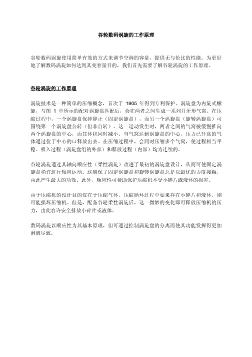
数码涡旋以顺应性为其基本原理,但可通过控制涡旋盘的分离而使其功能发挥得更加 淋漓尽致。
涡旋盘中的压 缩由一个 旋转涡 旋盘和一个固 定涡旋盘 的互动 形成。当其中 一个涡旋 盘旋转
气体被吸入 螺旋后 封锁开 放通道。
当螺旋持续旋转时,气体被压 缩成两团更小的气窝,体积逐 渐减小。
当气体到达 中心口 时,达 到释放压力。
事实上,在运行过程中,所有 6 个气体通道始终都处于 不同的压 缩状态,形成近乎持续 的吸入和
图1
谷轮数码涡旋
使用一个电磁阀以及排气腔与吸气口的旁通连接即可实现涡旋盘的受控分离(参见图 2)。涡卷的设计使上涡旋盘可与下涡旋盘垂直分离 1mm。上涡旋盘上部附有一个活 塞,在向上运动时将提起上涡旋盘。当电磁阀关闭时,数码涡旋和普通的涡旋式压缩 机一样工作,且经压缩的气体通过普通管道在高压下排出。而当电磁阀开启时,排气 腔与吸气口相连,由此释放出部分排气压力。这可以使控制活塞的压力减小,从而使 活塞上升,随即提起上涡旋盘。一旦涡旋盘分离后,任何通过其中的气体不再受到压 缩。
谷轮数码涡旋的工作原理
谷轮数码涡旋使用简单有效的方式来调节空调的容量,提供无与伦比的性能。为更好 地了解数码涡旋如何达到其变容量目的,我们首先需要了解谷轮涡旋的工作原理。
谷轮涡旋压缩机高温保护原理

谷轮涡旋压缩机高温保护原理谷轮涡旋压缩机高温保护原理摘要:谷轮涡旋压缩机是一种高效节能的压缩机,广泛应用于工业领域。
为了确保谷轮涡旋压缩机的安全可靠运行,需要对其进行高温保护。
本文将介绍谷轮涡旋压缩机高温保护的原理和应用。
关键词:谷轮涡旋压缩机;高温保护;原理;应用。
第一节:谷轮涡旋压缩机的工作原理谷轮涡旋压缩机是一种无油、无冷却剂的压缩机,利用谷轮涡旋技术将气体压缩。
其工作原理可以简单描述为以下几个步骤:1.首先,气体通过进气口进入压缩机的工作腔,进入后与旋涡腔内的气体进行交互。
2.旋涡腔内的叶轮开始高速旋转,通过离心力将气体压缩。
3.压缩后的气体被推入压缩腔,气体在腔体内进一步压缩。
4.最后,气体通过排气口排出压缩机,完成一个循环过程。
通过谷轮涡旋技术,可以实现高效能的气体压缩,并且由于无需冷却剂和油润滑,使得谷轮涡旋压缩机更加环保和节能。
第二节:谷轮涡旋压缩机的高温保护原理在工业应用中,谷轮涡旋压缩机会遇到高温环境,其中旋涡腔和压缩腔是最容易受到高温影响的部分。
高温环境不仅会影响谷轮涡旋压缩机的正常工作,还可能引发机器故障和事故。
为了保护谷轮涡旋压缩机,通常采用以下几种高温保护原理:1.温度传感器监测:在谷轮涡旋压缩机的旋涡腔和压缩腔内安装温度传感器,实时监测气体温度。
一旦温度超过设定的阈值,压缩机将自动停止工作,通过报警系统通知操作人员处理问题。
2.冷却系统:通过增加冷却系统的供气量和供水量,将常温气体和水蒸气注入谷轮涡旋压缩机内进行冷却,以降低温度。
这种方法可以在短时间内有效降低温度,但需要注意水量和水质的控制,以免引起其他问题。
3.风扇散热:通过在谷轮涡旋压缩机周围设置风扇,利用自然风或人工风扇进行散热。
这种方法适用于小型谷轮涡旋压缩机,可以有效降低温度,但无法承受极高的温度。
以上三种高温保护原理通常结合使用,以确保谷轮涡旋压缩机在高温环境下的安全运行。
第三节:谷轮涡旋压缩机高温保护的应用谷轮涡旋压缩机广泛应用于石油、化工、电力、冶金、纺织等工业领域。
- 1、下载文档前请自行甄别文档内容的完整性,平台不提供额外的编辑、内容补充、找答案等附加服务。
- 2、"仅部分预览"的文档,不可在线预览部分如存在完整性等问题,可反馈申请退款(可完整预览的文档不适用该条件!)。
- 3、如文档侵犯您的权益,请联系客服反馈,我们会尽快为您处理(人工客服工作时间:9:00-18:30)。
蒸发温度 oC
0 28.73 32.26 35.50 38.16 40.53 42.68 44.68 46.59 48.49 50.44 52.51 17.32 15.64 14.13 12.79 11.59 10.50 9.52 8.60 7.75 6.93 6.12 34.71 38.68 42.25 45.06 47.56 49.86 52.12 54.46 57.01 59.91 63.30 22.23 19.85 17.79 16.00 14.45 13.09 11.88 10.78 9.75 8.75 7.73
13.79 12.46 11.26 10.19 9.20 8.29 7.43 6.61 5.79
26.62 29.63 32.10 34.21 35.95 37.59 39.28 41.14 43.31
17.57 15.76 14.18 12.79 11.55 10.42 9.35 8.31 7.25
电气代码 50 Hz
M 380 - 420 V D 380 - 420 V
60 Hz 460 V
压缩机配置说明
压缩机型号
ZB130KQ/E
ZB150KQ/E ZB190KQ/E ZB220KQ/E
电机代码 TED TWM
BOM配置代码 550 551 522 523
焊接接口 √
√
螺纹接口 √ √
视油镜 √ √ √ √
5 54.11 58.61 62.91 67.00 70.84 74.42 77.72 80.73 83.41 85.75
27.66 24.86 22.33 20.08 18.08 16.33 14.82 13.52 12.43 11.53
68.29 73.60 78.51 83.06 87.29 91.22 94.88 98.32 101.56 104.64
22.36 19.97 17.81 15.86 14.11 12.56 11.18 9.97 8.92
37.94 42.05 45.67 48.92 51.53 53.80 55.76 57.46 58.91
25.63 23.25 21.04 19.00 17.13 15.42 13.87 12.48 11.23
22.37 20.03 18.01 16.27 14.76 13.45 12.30 11.25
22.40 20.07 18.06 16.33 14.84 13.54 12.39 11.36
7
制冷量
TED/TWM: 380-420V; 三相, 50Hz
型号 Q
ZB190KQ TWM P
Q ZB220KQ TWM
特点及优势
• 谷轮特有的径向和轴向柔性涡旋设计, 优越的抗液击能力和杂质容忍度, 同时提升了压缩机的运行效率 和可靠性
• 压缩腔对称分布及连续压缩, 较低的噪音和振动水平 • 内置排气温度保护装置, 保证压缩机长期稳定可靠运行
- ZB130沿用谷轮ASTP涡旋温度保护装置 - ZB150-ZB220涡旋盘内置排气温度传感器, 与外置保护模块相连 • ZB130集成CoreSense诊断模块, 具备缺相保护, 相序保护, 电机过热保护和远程通讯等功能 • IP54及以上防护等级, 有效防水防尘 • 多种制冷剂可选 • 结构紧凑, 对比传统活塞重量减轻约20%, 节省运输成本 • 螺纹接口和标配视油镜, 适用于并联应用, 具有优异的季节能效比
6
制冷量
TED/TWM: 380-420V; 三相, 50Hz
型号 Q
ZB130KQ TED P
Q ZB150KQ TWM
P
冷凝 温度
oC
65 60 55 50 45 40 35 30 25 20 15 65 60 55 50 45 40 35 30 25 20 15 65 60 55 50 45 40 35 30 25 20 15 65 60 55 50 45 40 35 30 25 20 15
谷轮涡旋™ ZB大型商用冷冻压缩机
产品手册 50Hz
采用先进的技术致力于为客户提供世界级的产品
艾默生在家用、商用和工业应用方面,是世界领先的供热、通风、空调和冷冻解决方案提供商,我们为客户提 供先进的技术解决方案、完善的技术支持和培训服务。 从20世纪40年代的第一台半封闭式压缩机和20世纪50年代的全封闭式压缩机,从20世纪80年代的高效Discus 半封闭压缩机和20世纪90年代的空调和制热用涡旋压缩机,到今天最新的Stream半封闭压缩机以及数码涡旋 压缩机,在过去的80多年里,我们向市场引入了众多的创新科技。 不仅如此,我们还为空调和冷冻市场提供非同一般的解决方案。艾默生是空调和冷冻业界主要的解决方案提 供商,旗下的谷轮品牌产品提供了多种多样的解决方案:从主要冷媒都适用的涡旋和半封闭压缩机,到可变 能力输出调节的压缩机以及装备了智能电子控制元器件的压缩机,艾默生引领压缩机科技发展至新的高度。
17.65 15.97 14.47 13.14 11.95 10.89 9.92 9.03
17.71 16.03 14.54 13.21 12.03 10. 60.69 64.10 67.36 70.62 73.99 77.62
56.91 61.13 64.98 68.58 72.07 75.59 79.26 83.22
5 36.02 39.70 42.96 45.88 48.53 50.97 53.27 55.50 57.73 60.03
17.49 15.81 14.31 12.97 11.77 10.69 9.71 8.80 7.96 7.14
43.60 47.50 50.91 53.94 56.75 59.45 62.19 65.10 68.31 71.96
P
冷凝 温度
oC
65 60 55 50 45 40 35 30 25 20 15 65 60 55 50 45 40 35 30 25 20 15 65 60 55 50 45 40 35 30 25 20 15 65 60 55 50 45 40 35 30 25 20 15
-12
30.51 33.19 35.76 38.34 40.48 42.48 44.30 45.93 47.35
ZB19
ZB21
ZB26
ZB29
R404A - 50Hz
ZB涡旋2~15HP
ZB38 ZB45 ZB48 ZB58 ZB66 ZB76
ZB大型涡旋20~30HP ZB95 ZB114 ZB130 ZB150 ZB190 ZB220
注: 制冷量基于 -10°C蒸发温度, 45°C冷凝温度, 20 °C回气温度, 0K过冷度。
42.21 46.28 49.89 53.11 55.75 58.06 60.09 61.85 63.39
25.81 23.39 21.16 19.10 17.22 15.52 13.98 12.60 11.38
-5
38.50 41.88 45.42 48.35 51.11 53.68 56.04 58.17 60.04 61.64
针阀 √ √ √ √
5
应用范围
冷凝温度 (°C) 冷凝温度 (°C)
ZB130 - ZB220KQ
70
65
60
55
50
45
40
35
30
25
20
15
10
5
0
-25
-20
-15
-10
-5
0
蒸发温度 (°C)
R22
5
10
15
注:
20°C 回气温度
11K 吸气过热度
ZB130 - ZB220KQE
70
65
22.31 19.94 17.90 16.13 14.60 13.26 12.08 11.00 10.00 9.02
R22
10 43.47 47.47 51.07 54.34 57.35 60.17 62.87 65.51
12 46.60 50.75 54.51 57.95 61.14 64.14 67.02 69.85
60
55
50
45
40
35
30
25
20
15
10
5
0
-25
-20
-15
-10
R404A
-5
0
蒸发温度 (°C)
5
10
15
注:
ZB130KQE, 20°C 回气温度
ZB150-220KQE, 20°C 回气温度
ZB 中高温涡旋产品线
制冷量, kW 60 55 50 45 40 35 30 25 20 15 10 5 0 ZB15
-5
25.40 28.38 31.10 33.29 35.24 37.02 38.70 40.36 42.05 43.85
15.46 13.96 12.62 11.42 10.34 9.35 8.43 7.57 6.75 5.93
30.65 34.09 37.16 39.49 41.55 43.47 45.39 47.43 49.74 52.44
蒸发温度 oC
0 43.69 47.72 51.87 55.43 58.80 61.96 64.88 67.54 69.92 72.01 73.79 27.62 24.77 22.20 19.89 17.83 16.01 14.41 13.02 11.83 10.83 10.00 55.41 60.55 65.55 69.70 73.50 76.96 80.13 83.04 85.73 88.21 90.54 32.42 29.39 26.61 24.07 21.76 19.68 17.83 16.20 14.79 13.59 12.59