调节器说明书(自励)
LIXISE力可赛 SX460发电机自动调压板使用手册-中文

SX460發電机自動電壓調節器使用手冊适用于自励式无刷式发电机1. 技術參數检测与检测与电源电源电源输入输入 电压 95 ~ 132 V AC 或190 ~ 264 V AC 电压调节率 < ±1.5% (发动机转速变动在4%内)单相 以跨接铜片设定 电压建立 在A VR 输入端子需剩磁电压5 V AC 以上频率 50/60 Hz 以跨接铜片设定 温差稳定度 每℃变化,电压漂移0.05% 输 出 电压 207 V AC 输入时 最大90 VDC 消耗功率 最大10 Watt电流 连续4A ,非连续为10秒内10A 低频保护 出厂设定点:95% Hz电阻 最小15 Ohm斜率:下降至30 Hz 时为170% 外部电压调节 用1K Ohms 1 Watt 电位器时为±7% 尺 寸 135mm L * 100mm W * 49mm H 电压缓慢建立时间2秒重 量243公克 ± 2%2. 接線 (如圖四、五)2.1 将发电机之磁场引线连接于F+、F-接口. 2.2 连接检测电源线于7、8 (出厂设定220V ,若需设定110V 时请将3、4跨接短路). 2.3 外部电压调节器如图四 (视需求). 2.4 选择50Hz 或60Hz. 2.5 选择R.S.T 三相电压.注:建议使用一较高遮断容量之保险加装于电源(如图四),熔丝容量须依实际满载励磁场电流的120%.3. 使用時注意事項3.1 安装时注意事项:(配置参考图一). 3.1.1 安装、连接、调节、检查的作业由有专业知识人员实施. 3.1.2 将调节器安装于发电机内防潮、防蚀且防止他人易碰触的地方. 3.2 发电机运转时注意事项:3.2.1 在一般运转状况下,调节器表面温度会超过60℃. 3.2.2 运转时,请勿碰触调节器散热板,也不可将调节器散热板接地或触碰外壳,已张贴警告标志.3.3 开机程序: 3.3.1 初步设定:(1) 确定一切接线正确. (2) 将电压调节至最小.(3) 假如使用外部电压电位器,则调节至中点.(4) 调节稳定旋钮调节至最大.(5) 用110VDC 电压表或三用表接F+、F − ( F+接正、F −接负 ).(6) 用300VAC 表接交流输出端,检测交流输出电压. 3.3.2 系统开动:(1) 在空载状态下启动发电机,调节正确之转速,电压应建立于最低电压水平,假如不能建立电压时,(参阅5.以电瓶初期励磁或洽发电机商).(2) 缓慢调节电压调节钮至所需. (3) 顺时钟方向调节稳定调节钮直到出现不稳定状态时,再往反时钟方向调节至稳定点,即最适当之位置(参阅4.3.2),故意中断本调节器之电源1~2秒再恢复,假如电压仍保持稳定则不需进一步调节,否则需以反时针方向调节稳定钮.4. 調節4.1 低频调节 (U/F).4.1.1 在50Hz 使用时,将 “ 跨接铜片 ” 插于C 与50Hz 之间,在60Hz 使用时将 “ 跨接铜片 ” 插于C 与60Hz 之间. 4.1.2 U/F 旋钮为设定低频保护之频率拐点值,其设定步骤为:(1) 使发动机启动,且电压建立. (2) 调节发动机转速至所须之低频值. (3) 缓慢调节U/F 旋钮使红色低频指示灯亮,即可(出厂设定50Hz 时45Hz 、60Hz 时55Hz)。
励磁调节器参数设置说明

EXC9000调节器参数设置1、COMM1控制码:输入参数:菜单选择输出参数:Data1[0]:“0000”――修改运行参数,不写入EEPROM。
“1000”――修改运行参数,并写入EEPROM。
“2000”――读入EEPROM数据为运行参数。
“3A00”――请求发送录波数据。
A=0,发送本命令前到本命令时刻止记录的录波数据。
A=1,发送由IPC触发或阶跃试验记录的录波数据。
“40BC”――阶跃试验。
先上跃后下跃,间隔由B值(秒)确定。
C为阶跃量(%)。
“50AA”――修改单个运行参数,不保存,AA=参数编码(序号)。
2、电压放大系数Kavr输入参数:Kavr=?(倍)输出参数:Data1[1]=1000*Kavr3、PID调节器参数T1、T2传递函数:W(S)=(1+T1S)/(1+T2S)输入参数:T1=?(秒),T2=?(秒)输出参数:Data1[2]=1000*T1Data1[3]=1000*T24、PSS隔直参数Tq传递函数:W(S)=TqS/(1+TqS)输入参数:Tq=?(秒)输出参数:Data1[4]=1000*Tq5、PSS放大系数Kpss输入参数:Kpss=?(倍)输出参数:Data1[5]=1000*Kpss6、PSS第一级参数T1、T2传递函数:W(S)=(1+T1S)/(1+T2S)输入参数:T1=?(秒),T2=?(秒)输出参数:Data1[6]=1000*T1Data1[7]=1000*T27、PSS第二级参数T3、T4传递函数:W(S)=(1+T3S)/(1+T4S)输入参数:T3=?(秒),T4=?(秒)输出参数:Data1[8]=1000*T3Data1[9]=1000*T48、电流放大系数Kair输入参数:Kair=?(倍)输出参数:Data1[14]=1000*Kair9、恒IL调节参数T1、T2传递函数:W(S)=(1+T1S)/(1+T2S)输入参数:T1=?(秒),T2=?(秒)输出参数:Data1[15]=1000*T1Data1[16]=1000*T210、PI调节器参数Kp、Ti(用于过励限制)传递函数:W(S)= Kp+1/(TiS)输入参数:Kp=?,Ki=?输出参数:Data1[17]=100*KpData1[18]=1000*Ti11、电压预置值输入参数:ug=? (%)输出参数:data1[20]=100*ug12、过励限制值输入参数:I=? (%)输出参数:data1[21]=100*I13、强励限制值输入参数:I=? (%)输出参数:data1[22]=100*I14、最大电流允许时间输入参数:t=? (秒)输出参数:data1[23]=1000*t15、V/HZ限制值输入参数:V=? (%)输出参数:Data1[24]=100*V16、欠励限制值k、b欠励限制:Q=k*P-b输入参数:k=?, b=?输出参数:Data1[25]=1000*kData1[26]=1000*b17、空载励磁电流系数值Kilo空载励磁电流系数=额定空载励磁电流/额定励磁电流输入参数:Kilo=?输出参数:Data1[28]=1000*Kilo18、功率系数值Kpow功率系数值*功率测量值=功率显示值调整Kpow,使功率显示值=按PT、CT变比计算的实际输入有功或无功功率。
DEC-2000微机励磁调节器技术说明书
DEC-2000发电机励磁调节器技术说明书中国长江动力集团有限公司武汉长动电力电子技术有限责任公司目录第一章前言 (1)第二章装置主要特点 (2)2.1 装置特点 (2)2.2 装置适用范围 (4)第三章主要功能及技术指标 (6)3.1 装置主要功能 (6)3.1.1 调节及控制功能 (6)3.1.2 限制和保护功能 (7)3.1.3 其它辅助功能 (7)3.2 主要技术指标 (8)3.2.1 模数转换器输入参数 (8)3.2.2 开关量输入输出容量 (9)3.2.3 输出参数: (9)3.2.4 网络接口 (9)3.2.5 电源参数 (9)3.2.6 指标参数 (10)第四章系统配置 (11)4.1 电气配置 (11)4.1.1 励磁系统框图 (11)4.1.2 输入输出接口示意图 (11)4.1.3 硬件组成 (12)4.1.4 软件组成 (12)4.2 控制面板说明 (12)4.3 功率单元说明 (14)第五章基本原理 (14)5.1 基本原理 (14)5.2 单板原理 (16)5.3 软件说明 (19)5.3.1 主调度程序 (19)5.3.2 中断程序 (20)第六章键盘、显示及操作 (26)6.1 键盘操作说明 (26)6.2 主画面显示 (27)6.3 主菜单显示 (29)6.3.1 测量显示 (29)6.3.2 参数设置 (30)6.3.3 保护投退 (34)6.3.4 开入状态 (34)6.3.5 传动试验 (35)6.3.6 系统试验 (36)6.3.7 故障追忆 (36)6.3.8 故障波形 (37)6.3.9 事件记录 (38)6.3.10 精度调整 (38)6.3.11 机组参数 (39)6.3.12 系统设置 (39)6.3.13 试验选项 (40)6.3.14 其它试验 (41)第七章上位机监控程序 (42)7.1 主画面 (42)7.2 状态显示 (43)7.3 故障记录及SOE (45)7.4 参数设置 (45)7.5 波形分析 (47)7.6 试验功能 (47)7.7 系统选项 (48)附录一: DCS 关于励磁系统设计指南 (49)附录二: PSS 试验方法及试验步骤 (50)第一章前言DEC-2000 微机励磁调节器是依托中国电力科学研究院的技术研制、开发并生产的新一代微机励磁调节器。
AS440自动电压调节器中文版说明书
AS440自动电压调节器中文说明规范安装和调整概述AS440是半波晶闸管相控型AVR和形式的一部分,用于无刷发电机的励磁系统。
该设计采用了表面贴装技术(SMT)的高集成度的特点,占地面积小的AVR。
通过在AVR的电源电路中使用有效的半导体来确保从剩余电平积累的正电压。
电源和电压检测电路具有独立的端子,如果需要持续的短路性能,可以直接从定子绕组获得励磁功率,或者从辅助绕组获得励磁功率。
AVR与主定子绕组和励磁线圈的励磁绕组相连接,以+/-1.0%的负载调节提供闭环控制输出电压。
AVR电压传感终端连续采样输出绕组用于电压控制目的。
为了响应这个采样电压,AVR控制供给励磁机磁场的功率,因此主磁场保持发电机输出电压在规定的范围内,补偿发电机的负载、速度、温度和功率因数。
频率测量电路持续地监控发电机的输出,并提供对励磁系统的低速度保护,通过以低于可设定的阈值的速度来降低输出电压。
对频率下滚点的出厂设置进行了手动调整(UFRO)。
这可以很容易地在字段中按下推链接的选择来更改为50或60Hz。
过励磁条件受限于AVR保护电路的安全范围内。
提供了远程连接的电压微调,允许用户控制发电机的输出。
提供一个模拟输入,允许连接到功率因数控制器或具有兼容输出的其他外部设备。
AVR拥有用于droop CT连接的设备,允许与其他类似装备的发电机并行运行。
技术参数检测输入电压跳线可选100-130Vac1相或190-264Vac1相频率50-60Hz输入功率电压100-264V ac1相频率50-60Hz通用电压输入电压为交流200V时,输出最大可达到直流82v。
电流连续输出为4A(见备注1).允许7.5A瞬间电流10秒.励磁电阻最小值为15Ω(电源电压低于175V时为最小10Ω)规格±1.0%(见备注2)热漂移AVR环境温度改变1℃,漂移值为0.03%(见备注3)经典系统响应AVR响应20ms90%励磁电流80ms97%输出电压300ms调节精度电压可调整范围≥±10%外接电阻1kΩ/1W(见备注4)增加阻值电压下降。
库台 EA480 发电机自动电压调节器 操作手册说明书

KUTAI ELECTRONICS INDUSTRY CO., LTD.TEL : +886-7-8121771FAX : +886-7-8121775Website : Headquarters : No.3, Ln. 201, Qianfu St., Qianzhen Dist., Kaohsiung City 806037, TaiwanEA480Generator Automatic Voltage RegulatorOperation ManualAnalog, single-phase sensing,Excitation output 5 Amp with half-wave rectifierFor use with self-excited, brushless generatorsCompatible with Newage Stamford AS480*Supports connection with Stamford Excitation Boost System (EBS)*Note:The manufacturer name and number are used for reference purpose only and do not imply that any part is the product of these manufacturer.SECTION 1 : SPECIFICATIONVoltage Sensing / Power Input (7,8) Average Reading Static Power DissipationVoltage 60 300 Vac, 1 phase 2 wire Max. 4 wattsFrequency 50/60 Hz (Jumper Selected)Quadrature Droop Input (S1, S2)Excitation Output (F1, F2) Input resistance 10 ohms110V 1 phase Continuous 31 Vdc 5A Sensitivity 0.07A for 5% voltage drop (PF= 0) Max. 45 Vdc 7.5A for 10 secs. Max. Input 0.33A220V 1 phase Continuous 63 Vdc 5AMax. 90 Vdc 7.5A for 10 secs. Under Frequency Protection (knee point factory preset) Note:If AVR is mounted externally to alternator 45 Hz for 50 Hz systemscontinuous current is reduced by 20% 55 Hz for 60 Hz systemsResistance Min. 6 ohms, Max. 100 ohm @ 110VMin. 13 ohms, Max. 100 ohm @ 220V Over Excitation ProtectionExcitation Voltage 70 Vdc +/- 10 %External Voltage Adjustment (1, 2)Time Delay 10 – 15 secondsMax. +/- 10% @ 1K ohm 1 watt potentiometerUse 7.5K ohms resistor to enable 110Vac sensing Voltage Thermal DriftLess than 3% at temperature range -40 to +70 ˚C Voltage RegulationLess than +/- 0.5% (with 4% engine speed governing) EnvironmentOperating Temperature -40 to +60 ˚CBuild up Voltage Storage Temperature -40 to +85 ˚C4 Vac 25 Hz residual volts at power input terminal Relative Humidity Max. 95%Vibration 5.5 Gs @ 60 HzSoft Start Ramp Time3 seconds +/- 10% Dimensions130.0 (L) x 90.0 (W) x 39.0 (H) mmTypical System Response 5.12 (L) x 3.54 (W) x 1.54 (H) inchLess than 20 millisecondsWeightEMI 260 g +/- 2%Built-in Harmonic suppression 0.573 lb +/- 2%___________________________________________________________________________________________ 2EA480___________________________________________________________________________________________ EA4803SECTION 2 : APPEARANCE / DIMENSIONS / INSTALLATION DRAWINGUnit : mm [inch]SECTION 3 : LED INDICATORS AND POTENTIOMETER ADJUSTMENTS1, 2:External VR Input used ;Use 7.5K ohms resistor enable 110Vac sensing. 7, 8:Power Input: to ExcitationS1, S2:InputMax. Input 0.33AD :Stability range:> 100KW:< 100KW Slow :< 100KW Fast :Under Frequency :60 Hz system :50 Hz system STAB :StabilityF1, F2:Connect to generator excitation fieldU/F :Under Frequency when U/FUFRO :Under Frequency Protection50 Hz system :Adjustable 40 – 51 Hz Factory preset 45 Hz 60 Hz system :Adjustable 50 – 61 Hz Factory preset 55 HzVOLT :Voltage adjustment DROOP :Voltage droop (for parallel operation)Figure 1 Outline DrawingFigure 2___________________________________________________________________________________________ 4EA480SECTION 4 : CONNECTION DIAGRAMSFigure 3 220 VacFigure 4 380/440 Vac※ Use only replacement fuses specified in this user manual.※ Appearance and specifications of products are subject to change for improvement without prior notice.。
EA63-4 发电机自动电压调节器使用手册说明书
KUTAI ELECTRONICS INDUSTRY CO., LTD.TEL : +886-7-8121771FAX : +886-7-8121775Website : Headquarters : No.3, Ln. 201, Qianfu St., Qianzhen Dist., Kaohsiung City 80664, TaiwanEA63-4Generator Automatic Voltage RegulatorOperation ManualSelf Excited Automatic Voltage RegulatorCompatible with Basler AVC63-4A** All manufacturer names and numbers are used for reference purpose only and do not imply that any part is the product of these manufacturer.___________________________________________________________________________________________ 2EA63-4SECTION 1 : SPECIFICATIONSensing Input EMI SuppressionVoltage 95 - 139 Vac +/-10% @ 120 Vac Internal electromagnetic interference filtering 190 - 277 Vac +/-10% @ 240 VacFrequency 50 / 60 Hz, selectable Static Power DissipationMax.15 watts Power InputVoltage 95 - 139 Vac +/-10%, 1 phase 2 wire Under Frequency Protection (Factory Presets) Frequency 45 / 65 Hz Knee point adjustable range 45 - 55 HzExcitation Output Over Excitation ShutdownVoltage Max. 63 Vdc Field volts shut down after a time delay Current Continuous 4A If exciter field volts exceed 95 Vdc +/- 5% Intermittent 7A for 60 secs.9A for 10 secs. Voltage Thermal DriftResistance Min. 15 ohm Max. 100 ohmLess than 3% at temperature range -40 to +70 ˚C Fuse Spec. Slow blow 5 x 20mm S505-6.3A / 250VEnvironmentExternal Voltage AdjustmentOperating Temperature -40 to +60 ˚C Max. +/- 15% @ 10K ohms 1 watt potentiometer Storage Temperature -40 to +85 ˚CRelative Humidity Max. 95% Voltage RegulationVibration 1.5 Gs @ 5 – 30 Hz Less than +/- 1% ( with 4% engine governing ) 5.0 Gs @ 30 – 500 HzDimensionsBuild Up Voltage140.0 (L) x 125.0 (W) x 48.0 (H) mm 5 Vac residual volts at power input terminalWeight280 g +/- 2%Frequency Compensation Curves Figure 1___________________________________________________________________________________________ EA63-43Unit : mmSECTION 2 : OPERATION PROCEDURE2.1 Stability Adjust Rheostat (STAB)2.1.1 An internal screwdriver adjustable potentiometerprovides adjustment to the response rate of the generator output voltage to a change in load.2.1.2 Clockwise rotation of this adjustment provides anincrease in the response time and therefore decreases the amount of voltage overshoot (increased stability).Counter-clockwise rotation of this adjustment provides a decrease in the response time (faster response time) and therefore increases the amount of voltage overshoot (decreased stability).2.2 OperationThe following system operation procedures provide instructions for adjusting the EA63-4 voltage regulator. Symptoms resulting from a faulty regulator and certain generator system problems are included, together with suggested remedies. 2.3 Preliminary Set-Up2.3.1 Verify that the voltage regulator specificationsconform with the generator system requirements.2.3.2 Ensure that the regulator wires are as follows: ● If the remote voltage adjust rheostat is not to be connected, ensure terminals 6 and 7 are shorted with a jumper.Figure 3 Outline DiagramTypical Time Delay Characteristic CurveFigure 2___________________________________________________________________________________________ 4EA63-4● If a 55 Hz “corner frequency” for 60 Hz systems is desired, ensure that the Hz 1 and Hz 2 terminals are open. If a 45 Hz “corner frequency” for 50 Hz systems is terminals are shorted together with a jumper.● For 120V nominal sensing, ensure that terminals V1 and V2 are not connected. For 240V sensing, ensure that terminals V1 and V2 are connected together.2.3.3 Ensure the voltage regulator is correctlyconnected to the generator system.2.3.4 Install the fuses as described in Fuses.2.3.5 Set the regulator VAR and external VAR (if used)as follows :2.4 System Star-Up2.4.1 Perform preliminary set-up as described in theabove paragraphs.NOTE :All voltage readings are to be taken with an average reading voltmeter.2.4.2 Start prime mover and bring up to rated speed.RESULT :Voltage should build up. If not, perform Field Flashing.2.4.3 Slowly adjust the regulator VAR CW until thegenerator output voltage reaches the nominal value. If used, adjust the remote VAR to set the generator voltage to the exact value desired.RESULT :Voltage should build up to rated value. If voltage does not build up to rated value, check generator for short or excessive load.2.4.4 Check regulator normal operating and loadingconditions.RESULT :Voltage regulation should be better than +/-1.0% no-load to full-load. If regulation is not within this range, perform the following steps :● Voltage reduction under load may be due to speed change from no load to full load. causing the frequency compensation (U/F) circuit to reduce voltage at lower frequencies.● Replace voltage regulator.2.5 Operational Test2.5.1 Connect the test setup as shown in the followingfigure, Operational Test. Do not apply power. Ensure that the light bulb is rated for 120V and is less that 100W. Complete the following steps before proceedingwith the system start-up.2.5.2 Adjust the regulator VAR and/or remote VAR,and the STABILITY Adjust to maximum CCW.2.5.3 Apply 120V, 50/60 Hz power to the regulator. The light bulb should illuminate.2.5.4 Slowly adjust the regulator VAR control CW. Atthe regulation point, the light bulb should extinguish. Small adjustments above and below this level should cause the light bulb goes on and off rapidly.2.5.5 Rotate the STABILITY ADJ fully CW. Now adjustthe regulator VAR above and below the regulation point. The light bulb should still to off and on, but the transition from off to on (and vice versa) should be much slower than in the paragraph above. The following notes ( ) apply to theinterconnection diagrams :(1) If external pot is not used, short terminals 6and 7.(2) For 50 Hz, short terminals Hz 1 and Hz 2 andleave open for 60 Hz.(3) Item not supplied by KUTAI ELECTRONICS. (4) For 120V Nominal sensing, make noconnection to terminals V1 and V2.For 240V Nominal sensing, short terminalsV1 and V2 together.(5) Select fuses with high interrupting capacity.___________________________________________________________________________________________ EA63-45Interconnection Diagram, 127 / 220 V Nominal,3-phase, 4-WireFigure 43-phase, 4-WireFigure 53EXCITATION ON-OFF SWTCH NOTE : 3IF GLASE TYPE FUSE IS USEDENCLOSE FOR SAFETYInterconnection Diagram, 127 / 220 V Nominal,1-phase, 3-WireFigure 6 Operational TestFigure 7。
LIXISE R230无刷柴油发电机自动励磁调压板使用说明书-中文
R230發電机自動電壓調節器使用手冊1. 技術參數检测与检测与电源电源电源输入输入 电压 120 V AC (90 ~ 140 V AC) 消耗功率 最大6 Watt单相二线 50/60Hz低频保护 频率 47 / 57Hz (可调式) 输 出 电压 120 V AC 输入时 最大100 VDC 励磁阻抗 电阻 最小15 Ohm电流 连续8A ,非连续为10秒内10A 过励磁自动关闭 调压精度 小于 ±1% (发动机转速变动在4%内) 电压建立在A VR 输入端子需剩磁电压5 V AC 以上 励磁电流超过8ADC ,则先经延迟时间后自动关闭;励磁电流大于10ADC ,则立即关闭 外部电压调节 用1K Ohms 0.5Watt 电位器时为±5% 尺 寸 140mm L * 75mm W * 51mm H 温差稳定度 每℃变化,电压漂移0.03% 重 量 310公克 ± 2% EMI 抑制 内建电磁干扰滤波器图一 尺寸图低频保护设定过低低频保护设定过低,,可能导致AVR 及励磁机损坏. 建议!! 使用60Hz 时,设为57Hz 使用50Hz 时,设为47Hz 2. 接線2.1 熔丝安装使用8A / 250V 高遮断容量熔丝,当系统异常时,可保护AVR 与设备.2.2 110V 、0V 端子为A VR 检测及电源输入,若发电机系统为220V 时(请参考图二、三). 2.3 E+、E – 端子为励磁输出端,接至发电机励磁场(励磁阻抗最小8Ω). 2.4 VR(如图二、三)外部电压调节端子,将跨接线拆除在端子两端跨接一电位器 1K Ω 1/2W 调节范围±5%. 2.5 Hz (如图二、三)频率设定,跨接为50Hz打开为60Hz ,出厂默认值47 / 57Hz. 2.6 设定步骤如下(1) 将U/F ADJ 旋钮反时计调至最大. (2) 启动发电机并调到额定电压值. (3) 调节发电机频率至所须 “低频” 保护频率. (4) 缓慢调节U/F ADJ (顺时针),当发电机电压,开始下降时即可.3. 操作說明3.1 在发电机启动前请如下步骤确认: 3.1.1 起始设定A. 确认调压板规格是否符合系统需求?B. 确认调压板接线是否如下:C. 确认AVR 正确连接于发电机系统.D. 设定 “ VOLT ADJ ” AVR 电压调节与外部电压调节如下:(1) “ VOLT ADJ ”内部电压调节钮反时针调至最大. (2) 外部电压调节钮调至中央位置. E. “STAB.”调至中央位置. 3.2 系统起动3.2.1 完成如上述 “ 起始设定 ”.3.2.2 启动发电机且至额定转速(发电机应建立电压,如无请进行 “ 励磁 ” ) 3.2.3 缓慢顺时针调节 “ VOLT ADJ ” 钮至发电机额定电压. 3.2.4 缓慢顺或反时针方向调节“ STAB ”在励磁电压摆动至最小(几乎静止)时即可.注:当电压无法建立时当电压无法建立时,,请检查发电机回路是否短路? 或剩磁电压太低. 3.2.5 确认发电机工作正常,能承受的负载下,调压精度应小于 ±1% (空载至满载),如无法达到时,检查如下:(1) 加负载时发电机频率是否下降到“低频保护” 频率. (2) 更换新AVR.注:AVR 所读取及演算均为平均值.3.3 A VR 测试3.3.1 如图四接线,灯泡电压为120V ,且勿超过100W. 3.3.2 A VR 上的 “电压调节” 与外部电压调节(如有),稳定调节均顺时针调至最大.3.3.3 供应120V AC 50/60Hz 电源到A VR ,此时灯泡应亮起. 3.3.4 反时针缓慢旋转 “电压调节” 到某区段时灯泡开始熄灭,在这区段上来回转动,灯泡会亮---灭---亮---即表示A VR 的大部份功能是完好的.图二 120 / 240V 1ψ 3W 接线图三 120 / 208V 3ψ 4W 接线※ 请用原厂备份熔丝。
发电机自动电压调节器说明书AVR
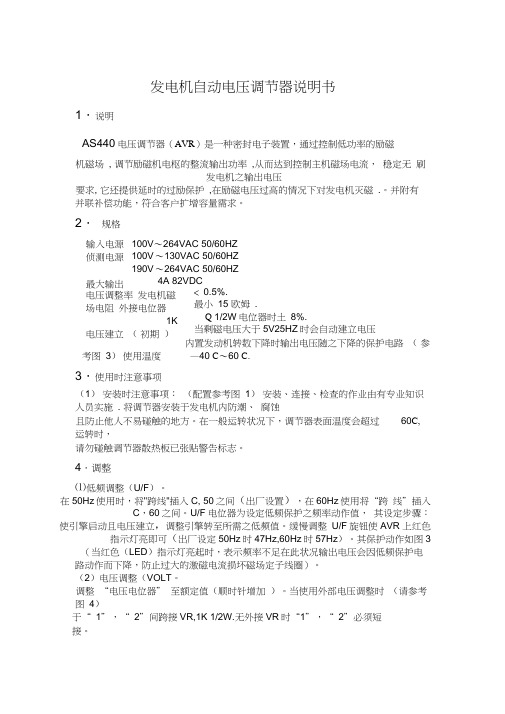
发电机自动电压调节器说明书1.说明AS440电压调节器(AVR )是一种密封电子装置,通过控制低功率的励磁机磁场 , 调节励磁机电枢的整流输出功率 ,从而达到控制主机磁场电流, 稳定无 刷发电机之输出电压要求, 它还提供延时的过励保护 ,在励磁电压过高的情况下对发电机灭磁 .。
并附有并联补偿功能,符合客户扩增容量需求。
2. 规格100V 〜264VAC 50/60HZ100V 〜130VAC 50/60HZ190V 〜264VAC 50/60HZ4A 82VDC < 0.5%. 最小 15 欧姆 . Q 1/2W 电位器时土 8%. 当剩磁电压大于5V25HZ 时会自动建立电压 内置发动机转数下降时输出电压随之下降的保护电路 ( 参考图 3) 使用温度 —40 C 〜60 C.3.使用时注意事项(1) 安装时注意事项: (配置参考图 1) 安装、连接、检查的作业由有专业知识人员实施 . 将调节器安装于发电机内防潮、 腐蚀且防止他人不易碰触的地方。
在一般运转状况下,调节器表面温度会超过 60C, 运转时,请勿碰触调节器散热板已张贴警告标志。
4.调整⑴低频调整(U/F )。
在50Hz 使用时,将"跨线"插入C, 50之间(出厂设置),在60Hz 使用将“跨 线”插入C ,60之间。
U/F 电位器为设定低频保护之频率动作值, 其设定步骤:使引擎启动且电压建立,调整引擎转至所需之低频值。
缓慢调整 U/F 旋钮使AVR 上红色指示灯亮即可(出厂设定50Hz 时47Hz,60Hz 时57Hz )。
其保护动作如图3(当红色(LED )指示灯亮起时,表示频率不足在此状况输出电压会因低频保护电路动作而下降,防止过大的激磁电流损坏磁场定子线圈)。
(2)电压调整(VOLT 。
调整 “电压电位器” 至额定值(顺时针增加 )。
当使用外部电压调整时 (请参考 图 4)于“ 1”,“ 2”间跨接VR,1K 1/2W.无外接VR 时“1”,“ 2”必须短接。
小型压力调节器说明书

L-13SMINIATURE PRESSURE REGULATORSEASy TO AdjUSTU Designed for Applications with Limited Space and for Low-Flow or Dead-End ServiceU Small Package Size and Lightweight Construction U Corrosion-Resistant Anodized Aluminum ExteriorU Excellent Stability and Repeatability U Self Relieving U Low CostThe AR91 and AR92 Seriesminiature pressure regulators are compact, low-cost units that operate in pressure ranges up to 100 psi, with a maximum supply pressure of 250 psi.They provide dependable reliability and accuracy for low-flow and dead-end applications, but are not designed for critical flow applications. Each unit has a corrosion-resistant anodized aluminum body with a standard fluorocarbon diaphragm.SPECIFICATIONSEffect of Supply Pressure Variation (25 psig) on Outlet Pressure: <0.25 psig (17.02 mbar)Exhaust Capacity (5 psig Above 20 psig Setpoint): 0.1 to 0.3 SCFM (2.8 to 8.5 LPM) typicalMaximum Supply Pressure: 250 psig (17.2 bar)Flow Capacity at 100 psig (6.9 bar) Supply and 20 psig (1.4 bar) Outlet: 2.5 SCFM (71 LPM)Total Air Consumption @ Maximum Output: 3 SCFH (84.6 LPM)Port Size: 1⁄16-27 NPT or 5 mm metric threadMaterials of Construction: Body: Anodized aluminum Adjusting Screw: Plated steel Trim: Brass, acetal D iaphragm: Fluorocarbon with polyester fabric Knob: Acetal resin Spring: Music wireDimensions: 22.2 x 22.2 x 84.6 mm (0.875 x 0.875 x 3.33")Weight: 2.2 oz (0.06 kg)Mounting Options: Pipe or panelAR91-015, shown larger than actual size.Comes complete with operator’s manual.Ordering Example: AR91-015, miniature pressure regulator, 0 to 15 psig 1⁄16-27 NPT pressure connections.Corrosion-resistantanodized aluminum bodyAR90 Series。
EMRI KASR20 V1.7 自动电压调节器操作手册说明书
KASR20V1.1自动电压调节器 2010.02操作手册警告警告为了避免人身伤害或设备损坏,只有合格的技术人员才允许完成本手册所描述的操作。
.警告发电机在运行状态绝对不允许操作,除非有其他工程师可以在危险时将电源断开或停止原动机运转。
警告在AVR调节板边缘有危险电压存在,不正确的接线可导致电击或人身伤害;在维修,接线或移除接线之前,必须断开功率源。
对发电机不熟悉时,请不要进行操作,避免危险电压!由于区域原因,EMRI的产品不能运用或调试位于美国或加拿大区域的发电机设备!本手册未能覆盖设备的所有细节和变化,也未能提供安装和操作时可能出现的各种意外情况的数据。
所有 特性和选件的有效性和设计如有更改,恕不事先通知。
如果需要更多的资料,请与EMRI电气公司联系。
目录1. 引言1.1 1.2 1.3 1.4 1.52.1 2.2 2.33.1概述AVR 布局 电气参数最大绝对额定值 调试信息4 5 6 6 72. 安装界面概述 调整概述 端口概述89 93. 操作与维护控制模式l 3.1.0低频 3.2 特殊应用 3.2.0并车操作99 9 94. 保护4.15.1 5.2 5.3 5.4 5.5 5.5 过电流95. 设定与调整发电机电压 稳定性 低频 调差 外部电位器 (S-T)开关设定 5.7.1开关 1: S-T 5.7.2开关2: ½ 相检测 5.7.3开关3: 稳定性选择 5.7.4开关4: 低频拐点 5.6出厂设定99 9 9 9 9 9 9 9 9 96. 意见与建议稳定性差 6.0.1举例 6.1附件6.2发电机绝缘测试 6.3激磁6.3.1手动充磁 6.3.2自动充磁 6.0 99 9 9 9 9 97. 接线图7.1 7.2 7.3 7.4 7.5 A.1 A.2400V 检测接线图 200V 检测接线图 230V 检测接线图 115V 检测接线图 辅助输入接线图 99 9 9 9附录安装概述 联系991. 引言1.1概述此手册包含KASR20自动电压调节器的安装,操作和维护的说明。
发电机自动电压调节器说明书.AVR

发电机自动电压调节器说明书.A V R-CAL-FENGHAI.-(YICAI)-Company One1发电机自动电压调节器说明书1.说明AS440电压调节器(AVR)是一种密封电子装置,通过控制低功率的励磁机磁场,调节励磁机电枢的整流输出功率,从而达到控制主机磁场电流,稳定无刷发电机之输出电压要求,它还提供延时的过励保护,在励磁电压过高的情况下对发电机灭磁.。
并附有并联补偿功能,符合客户扩增容量需求。
2.规格输入电源 100V~264VAC 50/60Hz侦测电源 100V~130VAC 50/60Hz190V~264VAC 50/60Hz最大输出 4A 82VDC电压调整率≤%.发电机磁场电阻最小15欧姆.外接电位器1KΩ1/2W电位器时±8%.电压建立(初期) 当剩磁电压大于5V25Hz时会自动建立电压.内置发动机转数下降时输出电压随之下降的保护电路 (参考图3)使用温度-40 ℃~60 ℃.3.使用时注意事项(1) 安装时注意事项:(配置参考图1)安装、连接、检查的作业由有专业知识人员实施.将调节器安装于发电机内防潮、腐蚀且防止他人不易碰触的地方。
在一般运转状况下,调节器表面温度会超过60℃,运转时,请勿碰触调节器散热板已张贴警告标志。
4.调整(1) 低频调整(U/F)。
在50Hz使用时,将 "跨线" 插入C,50之间(出厂设置) ,在60Hz使用将“跨线”插入 C,60之间。
U/F电位器为设定低频保护之频率动作值,其设定步骤:使引擎启动且电压建立,调整引擎转至所需之低频值。
缓慢调整U/F旋钮使AVR上红色指示灯亮即可(出厂设定50Hz时47Hz,60Hz时 57Hz)。
其保护动作如图3(当红色(LED)指示灯亮起时,表示频率不足在此状况输出电压会因低频保护电路动作而下降,防止过大的激磁电流损坏磁场定子线圈)。
(2) 电压调整(VOLT)。
调整“电压电位器” 至额定值(顺时针增加)。
GEX-200-技术及使用说明书
用户手册
北京科电亿恒电力技术有限公司
北京科电亿恒电力技术有限公司
版本修订记录
修订日期 20110724 内容
说 明 : 本 说 明 书 中 图 片 未 及 时 更 新 为 GEX-200 , 仍 为 GEX-100B,敬请谅解!
2ቤተ መጻሕፍቲ ባይዱ
GEX-200 自动电压调节器
文档版本: 20110724 中文
北京科电亿恒电力技术有限公司
目
录
第一章 概述.................................................................................................................................2 1.1 简介......................................................................................................................................2 1.2 性能特征..............................................................................................................................2 1.3 型号及适用范围..................................................................................................................3 1.3.1 型号定义:...............
发电机自动电压调节器使用手册_8452
EA341發電机自動電壓調節器使用手冊适用于永磁式(PMG)无刷式发电机与Newage MX341*相容( *本产品并非Newage 原厂产品,但能与其兼容 )总 公 司/高雄市前镇区千富街201巷3号Tel : 07-8121771 Fax : 07-8121775URL : ______________________________________________________________________________________2EA3411. 技術參數检测输入 电压 190 ~ 264 V AC 二相或三相 温差稳定度 每℃变化,电压漂移0.05% (注2) 频率 50/60 Hz 以跨接铜片选择 外部电压调节 用1K Ω 1 Watt 电位器时为±10% (注3) 电源输入 电压 170 ~ 220 V AC 三相三线 电压缓慢建立时间 2秒电流 每相3A 发电机电流输出限制 负载10 Ω 灵敏度范围 0.5 ~ 1A 频率 100 ~ 120 Hz 过励磁保护 90V (出厂默认值) 励磁场输出 电压 最大120 VDC 时间延迟固定为10秒电流 连续2.7A (注1)非连续为10秒内6A 低频保护 转折点 95% Hz (出厂默认值) (注4) 电阻 最小15 Ω斜率 下降至30 Hz 时为 170% 电压建立 在A VR 输入端子需剩磁电压5 V AC 以上 电压修正(模拟输入) 最大输入 ±5 VDC (注5)消耗功率 最大12 Watt 灵敏度 每1 VDC 可调节5%发电机电压 电流补偿 负载 10 Ω 输入电阻 1K Ω 调压精度 < ±1% (发电机转速变动在4%内) DROOP 压降输入 负载 10 Ω振 动 3.3G @ 100 ~ 2K Hz 灵敏度 0.07A 对应5%压降 (在PF= 0时) 相对湿度 < 95%最大输入 0.33A操作温度 -40 ~ 70℃ (注6)尺 寸 150mm L * 135mm W * 40mm H 储存温度 -40 ~ 85℃ 重 量394公克 ± 2%2. 概述2.1 励磁电源来自三相永磁式发电机(PMG),如此A VR 的控制电路可隔离受非线性负载所引发的影响,并能减低发电机端的射频干扰,能承受发电机的短路电流是PMG 发电机的另一特色. 2.2 此A VR 可以藉由检测发电机主绕组的电压,以控制提供给励磁机定子以及主转子的电力,来维持发电机输出电压介于指定的范围内,并补偿负载、转速、温度及发电机的功因。
ADVR-053 发电机自动电压调节器使用手册说明书
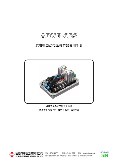
ADVR-053 发电机自动电压调节器使用手册适用于自励式无刷式发电机泛用型5 Amp AVR适用于170 – 520 Vac第一章概述ADVR-053为EA05A之进阶版,除沿袭EA05A之宽广电压调节范围、安装简易及快速反应外并增加了过励磁保护电路,防止检测电路断路及发电机过载. 以中央处理器(CPU)为核心,降低模拟组件的温度漂移。
并增加了低频U/F及过励磁O/E指示灯使调节更为精确.第二章技术参数检测电压输入静态消耗功率电压170 - 520 Vac 单相二线最大8 watts频率50/60 Hz,以指拨开关设定低频保护(出厂预设)电源输入50 Hz系统拐点值为45 Hz*电压100 - 300 Vac 单相二线60 Hz系统拐点值为55 Hz*励磁场输出(*拐点值为出厂预设值)电压连续63 Vdc @ 电源输入220 Vac 过励磁电压保护电流连续5A,非连续为10秒内7A 励磁电压78 Vdc +/- 5 % @ 电源输入220 Vac 励磁阻抗最小15 Ω、最大100 Ω延时5秒,可关闭此功能熔丝规格 5 x 20mm S505-5A / 250V慢熔型电压温度飘移外部电压调节-40至+70 ˚C,小于3%最大+/- 7% @ 1 KΩ 1 watt 电位器工作环境调压精度工作温度-40至+70 ˚C小於+/- 0.5% (频率变动在4%内) 储存温度-40至+85 ˚C电压建立相对湿度95%以下电源输入剩磁电压5 Vac以上振动 3 Gs @ 100 - 2K Hz电压缓慢建立时间尺寸3秒+/- 10% 107.0 (L) x 75.0 (W) x 48.5 (H) mmEMI抑制重量第三章接线3.1 A、C:为检测电源输入(1) 当SW-2 ON时,输入范围170 - 260 Vac (如图三、四).(2) 当SW-2 OFF时,输入范围340 - 520 Vac (如图五).3.2 B、C:为电源输入输入电压值范围为100 - 300 Vac.3.3 当发电机额定电压(相电压)为220 Vac时,输入电源B、C与检测电源A、C可并接一起(如图四)或分开独立电源(如图三)输入.※独立电源可降低电压调节率.3.4 F+、F-接发电机励磁场(J、K).(1) F+为励磁场输入+,F- 为励磁场输入-.(2) EXT. VR为外接电位器(1 KΩ 1W), 不用时须将两端短路.注:A、B、C、F+、F- 使用线径为AWG 16或1.25mm285 ˚C 600V以上.EXT. VR 外接线使用隔离绞线.第四章指拨开关设定4.1 SW-1频率选择SW-1置于ON时,适用于额定频率50 Hz.SW-1置于OFF时,适用于额定频率60 Hz.4.2 SW-2电压选择开关SW-2 ON时为220V系统,检测范围为170 - 260 Vac.SW-2 OFF时为440V系统,检测范围为340 - 520 V ac.4.3 SW-3过励磁电压保护SW-3 ON时无过励磁电压保护当发电机励磁电压过大时O/E指示灯亮,但AVR不做保护动作.SW-3 OFF时过励磁电压保护当发电机励磁电压过大时O/E指示灯亮,且关闭励磁场输出(参阅5.2).第五章保护系统5.1 低频保护当发电机频率下降时AVR为避免励磁电压过度提升,用户可设定一频率拐点值,当频率下降至拐点值以下时,AVR将降低励磁电压以保护AVR及励磁机.频率拐点值可由U/F旋钮及SW-1设定.当发电机频率低于拐点值时U/F指示灯亮,高于拐点值时U/F指示灯灭.5.2 过励磁电压保护当发电机过负载或检测电源断线时,励磁电压会迅速上升,导致AVR或励磁机损坏,ADVR-053可经由内部电路检测出,并关闭励磁场输出.当SW-3 OFF时,若励磁电压超过78 +/- 5 Vdc (电源输入@ 220V) 5秒以上时则AVR将关闭励磁电源同时O/E指示灯亮,此时发电机输出电压仅为剩磁电压。
EA06-220V 自励式无刷发电机自动调压器使用手册说明书
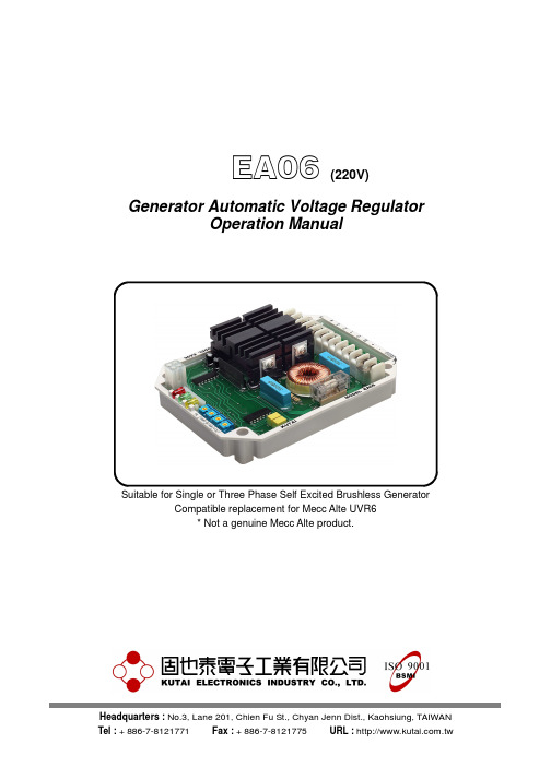
EA06 (220V) Generator Automatic Voltage RegulatorOperation ManualSuitable for Single or Three Phase Self Excited Brushless Generator Compatible replacement for Mecc Alte UVR6* Not a genuine Mecc Alte product.SECTION 1 : SUMMARYEA06-220V is equipped with 3 separate sensing inputs (1-2, 3-4, 5-6 terminals R.S.T phase), which can survey from single up to three phase voltages and check the average voltage from Y, YY or wiring accordingly to the generator requirement or user preference.The AVR is equipped with adjustable under frequency protection and over voltage protection to prevent generator from overloading and over excitation.The 3 LED each represents (Green) normal operation, (Red) under frequency and (Yellow) over excitation.The built in EMS filter helps to prevent possible interference from the AVR to the generator.SECTION 2 : SPECIFICATIONSensing Input (1-2, 3-4, 5-6) Soft Start Ramp Time Voltage 170 − 280 Vac / 270 − 520 Vac 4 sec. 1 or 3 phase selectable by wiringFrequency 50 / 60 Hz Unit Power DissipationMax.5 watts Power Input (+, 2)Voltage 50 − 280 Vac EMI SuppressionFrequency 50 / 60 Hz Internal EMI filteringOutput (+ , –) Over Excitation Protection Voltage Max. 63 Vdc @power input 220 Vac 25 −*********− 20 sec Current Continuous 6AIntermittent 7A for 10 sec. Under Frequency Protection Resistance 10 − 100 ohmsAdjustable range 42 − 62 Hz Fuse Spec. 5 x 20mm S505-6.3A / 250V(slow blow type) EnvironmentOperation Temperature -40 − +65 ˚C Voltage RegulationStorage Temperature -40 − +80 ˚C < +/- 1% ( with 4% engine governing ) Relative Humidity Max. 95%Vibration 1.5 Gs @ 5 – 30 Hz Build Up Voltage5.0 Gs @ 30 – 500 Hz Residual voltage at AVR terminal > 5 Vac @ 25 HzDimensionsThermal Drift150.0 (L) x 115.0 (W) x 41.0 (H) mm 0.03% per °C change in AVR ambientWeightExternal Volts Adjustment440 g +/- 2% +/- 5% 100K ohms 1/2 watt potentiometerATTENTION 1. AVR can be mounted directly on the engine, genset, switchgear, control panel, or any position that will not affects operation. For dimension reference, please see Figure 1. 2. All voltage readings are to be taken with an average-reading voltmeter Meggers and high-potential test equipment must not be used. Use of such equipment could damage the AVR. 3. Secure all wiring connection. Do not install AVR at a place with high vibrations to prevent loose connections. For safety do not touch the heat sink while in operation.Outline and Drilling DiagramSECTION 3 : WIRING / ADJUSTMENTS3.1 Field Excitation Wiring 「+, –」3.1.1 Connect AVR terminal 「+」to field 「+」, connectAVR terminal「–」to the field「–」.NOTEThe Exciter field resistance is between 10 − 100 ohm.3.1.2 If field resistance is less than 10 ohm whengenerator is under full load and the field voltage isunder the maximum output, please series asuitable wattage (W) resistor to have the overallfield resistance to equal to 10 − 100 ohm.3.2 Sensing / Power Input「1-2, 3-4, 5-6」3.2.1 Total of 3 sets of independent sensing inputs,each input voltage equals to 220V (Center), canbe series into Y or to connect to the generatoroutput (3 Phases) for example R-T, T-S, S-R, orjoint connected into a single phase sensing (SeeFigure 2 to 13).3.2.2 Terminal +, 2 is the AVR power input, voltagerange from 50 − 280V.3.3 Frequency Selection (60 Hz)When the 2 terminals marked as 60 Hz on the AVR is bridged, the system frequency is 60 Hz. In the contrary, when bridge is removed the system frequency is 50 Hz.3.4 External Voltage Adjustment VRConnect a 100K Ohms 1/2W voltage rheostat at VR terminals to enable a +/- 5% voltage adjustment from rated voltage.*The terminals must be bridged when the external voltage adjustment function is none required.3.5 Terminals B, 0 can remain not connected3.6 VOLT. Voltage AdjustmentUser can adjust the generator voltage by rotating the 「VOLT」potentiometer on the AVR. Rotate the potentiometer clockwise to increase voltage and decreasing when rotate counterclockwise. The voltage adjust rate is less than 1% when the power factor equals to 1 to 0.8 (PF 1 to 0.8) and frequency variation within 6%.3.7 STAB. Stability Adjustment3.7.1 Slowly and precise adjustment of 「STAB」potentiometer can change the respond timebetween the AVR and generator. Inadequateadjustment will cause voltage instability and overadjusting will cause sudden overly voltagevariation under heavy load. 3.7.2 Analogue type multi voltmeter is suggested whenadjusting the voltage stability. Adjust the 「STAB」potentiometer until the pointer on the multivoltmeter is oscillating to its minimal.3.8 Circuit Protection3.8.1 AMP. Over Excitation Protection Adjustment(Overload protection)Set the 「AMP」Overload protection value (25 to55 Vdc) according to the generator maximumexcitation voltage. When over excitation occurswait for 20 seconds then decrease the generatorvoltage to 30 to 50 Vac. When the Overexcitation protection is activated the yellow LEDwill illuminate, the higher the over excitationvalue is the shorter delay time becomes. Thegenerator will require stopping operation to reset.3.8.2 Hz. Under Frequency Protection Adjustment「Hz.」Is used to set the under frequencyprotection knee point. When the generatorfrequency declines to setting point, the generatorvoltage will also decrease in the same time toprevent high excitation current from damagingthe AVR or the exciter, adjustment procedure :Adjustment procedure :(1) Start generator and let voltage build up.(2) Adjust engine frequency to the appropriatelow frequency value.(3) Slowly adjust Hz. Potentiometer until the redLED illuminates.SECTION 4 : OPERATION PROCEDURE4.1 Please confirm the follow condition beforestarting the generator :4.1.1 Starting Setting(1) Confirm if the AVR specification conforms tothe system requirements ?(2) Confirm the AVR wiring ?(3) Confirm correct frequency selected ?(4) Confirm the generator rated voltage with theAVR sensing input ?(5) Adjust「VOLT」potentiometer fullycounterclockwise?Adjust「STAB」potentiometer to the centerposition?Adjust「AMP」potentiometer fully clockwise?Figure 2 Manual Field Flash4.1.2 Starting Generator(1) Reconfirm all setting and wiring.ATTENTIONThe AVR reading AC voltage are all average value.(2) Start generator and adjust to rated frequency.The first measured voltage value should be under the rated voltage. If not, then reconfirm the start setting.(3) Slowly adjust 「VOLT 」 potentiometer to therated voltage, at this time the generator voltage may become unstable. Adjust the 「STAB.」 potentiometer anticlockwise, until the oscillation stabilizes. Over adjustment may cause short oscillation when load applied or load type varies.SUGGESTIONAdjust the 「STAB.」 potentiometer to the point where the oscillation occurs and then adjust the potentiometer counterclockwise by 1/6 of rotation.(4) If voltage can not be adjusted or to the ratedvalue, please check to see if the generator frequency is too slow (Under frequency protection activated). If residual voltage is below 5 Vac, then please execute field flashing to help build up the residual voltage.(5) Make sure the generator and AVR are bothunder normal operation conditions.(6) The voltage adjustable range should be +/-1% under no load or full load. If the adjustable range in not within such range, please check the below :A. Generator under frequency (Lower than lowfrequency protection knee point).B. Severely deformed generator output waveform.C. Capacitive load over ratio (Power factor inlead).D. Change the AVR and restart.E. Under over excitation voltage protection(Overload protection).SECTION 5 : FIELD FLASHINGWhen the regulator is installed correctly but the generator is failed to generate power. Besides carbon brushes were worn out, here are two possible causes below.5.1 The polarity of field is inverseSolution :Exchange the connection of F+ and F-.5.2 The residual voltage is less than 5 Vac, Solution 1:5.2.1 Shut down generator, disconnect the wiringbetween AVR and generator then flash the field. Flashing duration = 3 seconds. (See wiring in Figure 2) Resistor 3 – 5 ohms for full wave AVR Resistor 5 – 10 ohms for half wave AVR Warning !! Over field flashing may damagethe field winding of generator.5.2.2 Restart generator and measure the residualvoltage by AC Voltmeter, if it is still less than 5 Vac, repeat the previous process, after several times, the residual voltage still cannot be built, Kutai EB500 is strongly recommended, see Figure 2.F+TS R5.3 Maintenance Regular maintenance to make sure the AVRsurface is clean and free from oil or moisture. All connection terminals and wirings must be firmly tightened and no signs of visible oxidation or erosion.WARNINGOverly field flashing may damage the AVR or generator excitation winding.Please make sure you have read and understand the contents of the instruction manual prior to installation. Incorrect wiring connection may result in irreversible damage to the product and other equipments.。
EA63-2.5S 自励式自动电压调节器使用说明书

KUTAI ELECTRONICS INDUSTRY CO., LTD.EA63-2.5SGenerator Automatic Voltage RegulatorOperation ManualSelf Excited Automatic Voltage Regulator220 / 480 VacUse with Kutai EP200 Paralleling Module for parallel operation* All manufacturer names and numbers are used for reference purpose only and do not imply that any part is the product of these manufacturer.SECTION 1 : SPECIFICATIONSensing Input EMI SuppressionVoltage 165 - 260 Vac @ 220 Vac Internal electromagnetic interference filtering 320 - 530 Vac @ 400 VacFrequency 50/60 Hz Static Power DissipationMax.10 watts Power InputVoltage 120 - 260 Vac, 1 phase Under Frequency Protection (Factory Presets)Knee point adjustable range 45 - 55 Hz Excitation OutputVoltage Max. 32 Vdc @ power input 120 Vac Voltage Thermal DriftMax. 63 Vdc @ power input 220 Vac Less than 3% at temperature range -40 to +70 ˚C Current Continuous 2.5AIntermittent 4A for 60 secs. EnvironmentResistance Min. 25 ohmsOperation Temperature -40 to +60 ˚C Fuse Spec. Slow blow 5 x 20mm S505-3.15A / 250V Storage Temperature -40 to +85 ˚CRelative Humidity Max. 95% External Voltage AdjustmentVibration 1.5 Gs @ 5 – 30 Hz Max. +/- 15% @ 5K ohms 1 watt potentiometer 5.0 Gs @ 30 – 500 HzVoltage RegulationDimensionsLess than +/- 1% ( with 4% engine governing ) 101.0 (L) x 69.0 (W) x 24.0 (H) mmBuild Up VoltageWeight5 Vac residual volts at power input terminal107 g +/- 2%TYPICAL FREQUENCY COMPENSATIONCURVES (See Figure 1)1. When the frequency of the generator is lower than the factory setting, the rated phase voltage will decrease to protect the regulator or exciter because of over exciter current,2. Factory Setting :47 Hz +/- 4%Unit : mm ATTENTION1. AVR can be mounted directly on the engine, genset, switchgear, control panel, or anyposition that would effects operation. Formounting, please see Figure 2.2. All voltage readings are to be taken with an average-reading voltmeter Meggers and high-potential test equipment must not be used. Use of such equipment could damage the AVR.3. Terminal :"Fast-On" terminals 6.35mm (1/4 inch).4. Improper setting of under-frequency protection could cause the output voltage of the unit to drop or become unstable under with changes in load. Avoid making anychanges to the U/F setting unless necessary.Figure 3Potentiometer and Connector Locations SECTION 2 : WIRING2.1 Operation2.1.1 F+, F-:Connect Exciter Field Power Circuit F+, F- 2.1.2 3, 4, P:Connect 3, 4 and 5 to the generator N, R, T3, 4:Power Input terminal4, P:Sensing Input terminal (See Figure 5).“J” jmper open sensing input 380 / 440 Vac“J” jmper close sensing input 220 / 240 Vac2.1.3 EXT.VR:Remove the jumper wire acrossterminals 6 and 7 and install a 5000 ohm rheostat.The two terminals must be by-pass when theexternal potentiometer is needless.2.1.4 The corner frequency can be adjusted by the U/FADJ rheostat on the AVR. Clockwise rotationresults in raising the corner frequency.(1) Adjust U/F Rheostat fully CCW.(2) Start the generator and set at rated voltage.(3) Adjust the generator frequency to the desiredknee point frequency.(4) Slowly adjust the U/F ADJ rheostat clockwise(CW) until the generator voltage just begins todecrease.(5) 「Stability Adjustment」clockwise slowly tochange the feedback time between AVR andthe generator. If the adjustment is too big, itmight cause the voltage instable. If too small,the load voltage will change too much atheavy load.(6) The suggestion is to trace by the multi-meterDCV. Adjust 「Stability Adjustment」and try tomake the multi-meter waving smaller. It canalso improve the full load’s voltage drift rate.SECTION 3 : OPERATION PROCEDURE Complete the following steps before proceeding with system start-up. 3.1 Preliminary Set-Up3.1.1 Verify that the Regulator specifications conformto the requirements of the generator system.3.1.2 Ensure the voltage regulator is correctlyconnected to the generator system.3.1.3 Set the regulator 「VOLT ADJ」and external「VOLT ADJ」as follow :Regulator 「VOLT ADJ」: Fully CCWRemote 「VOLT ADJ」: Centered3.2 System Start-Up3.2.1 Perform preliminary set-up as described in theabove paragraphs.3.2.2 Start prime mover and bring up to rated speed.Voltage should build up. If not, perform FieldFlashing.3.2.3 Slowly adjust the regulator VOLT ADJ CW untilthe generator output voltage reaches the normalvalue.3.2.4 Ensure the regulator and the generator undernormal operating conditions. The voltageregulation should less than +/- 1%. If theregulator is poor:(1) The generator frequency is too slow that isless than the keen point of under frequencyprotection.(2) The output wave of the generator isdeformation.(3) The ratio of capacity load is too high.SECTION 4 : FIELD FLASHINGWhen the regulator is installed correctly but the generator is failed to generate power. Besides carbon brushes were worn out, here are two possible causes below.4.1 The polarity of field is inverseSolution:Exchange the connection of F+ and F-.4.2 The residual voltage is less than 5 Vac,Solution 1:4.2.1 Shut down generator, disconnect the wiringbetween AVR and generator then flash the field.Flashing duration = 3 seconds. (See wiring inFigure 4)Resistor 3 – 5 ohms for full wave AVRResistor 5 – 10 ohms for half wave AVRWarning!!Over field flashing may damagethe field winding of generator.Figure 4 Manual Field Flash 4.2.2 Restart generator and measure the residualvoltage by AC Voltmeter, if it is still less than 5 Vac, repeat the previous process, after several times, the residual voltage still cannot be built, Kutai EB500 is strongly recommended, see Figure 4.F+TSR4.3 MaintenancePlease regular maintain the regulator, keep the surface clean and avoid oil and mist adhering on the surface. All connectors, wires, and external potentiometer should be installed tightly and to prevent erosion.Figure 5 3Ø 3W 380 / 480 VacFigure 6 3Ø 3W 220 / 240 VacFigure 7 3Ø 4W 380 / 440 VacFigure 8 3Ø 4W 380 / 440 VacFigure 9 Auxiliary Winding (220 / 240 / 380 / 440 Vac)。
savr-2000发电机励磁调节器使用说明书_secret

◆具有控制结构自适应和参数自适应的调节功能,配备在线专家系统。
◆ 全中文信息集成显示,模拟、数字显示一体化。
◆具备实时数据库及历史数据库,能够进行事件录波辅助分析,并给出有效提示。
◆ 保证发电机按要求升压、并网、增减无功负荷及逆变停机。
◆保证发电机稳定运行于空载、发电、调相、停机等工况。
◆定子电流容错
◆转子电流容错
◆发电机频率容错
◆有功功率及无功功率容错
◆开机令及停机令容错
◆增、减磁信号容错
◆油开关信号容错
4.智能调试及计算机辅助分析功能:
◆ 智能化调试:
调试软面板技术;
全中文图形化调试界面;
在线帮助系统;
◆ 计算机辅助分析系统:
各项试验专用数据库;
故障录波与计算机辅助分析
以工况转换为依据,进行不间断录波,形成历史数据库;
◆调压精度:<0.5%
◆移相范围:0-180度,上下限值可程序设置
◆调差:由软件设置无功调差率,正负及大小任选,级差为±0.33%。
◆频率特性:频率每变化1%,发电机端电压变化不大小额定值的±0.25%。
◆整定值调节速度:可编程,满足不大于1%每秒,不少于0.3%每秒。
◆响应时间
自并激励磁系统:上升<0.08S
2.可靠性高
2.1 先进的表贴(SMT)工艺:SAVR-2000发电机励磁调节器采用先进的表面贴装集成芯片,在机械结构上采用全封闭无风扇结构,由柜体、插箱、插件屏蔽板构成了三重防护,提高了装置整体的可靠性。
2.2 先进的测量方式:在一个周期内(20ms)对三相定子电压及三相定子电流进行多点交流采样,并由软件实时计算出有功功率、无功功率及定子电压、电流的有效值。因而响应速度快,测量精度不受波形影响。
EA03A 发电机自动电压调节器使用手册说明书

电话:07-8121771 传真:07-8121775 网址: 公司地址:台湾高雄市前镇区千富街201巷3号(邮政编码806-64)EA03A发电机自动电压调节器使用手册适用于自励式炭刷式发电机汽油发电机专用AVR___________________________________________________________________________________________ 2EA03A第一章 技术参数检测电压输入 电压温度飘移电压 18 - 20 Vac 单相二线 -40至+70 ˚C ,小于 5% 电源输入 工作环境 电压 60 - 90 Vac 单相二线 工作温度 -40至+60 ˚C 励磁场输出 储存温度 -40至+85 ˚C 电压 5 - 85 Vdc 相对湿度 95%以下 电流 连续3A ,非连续为60秒内4A 振 动 1.5 Gs @ 5 - 30 Hz 励磁阻抗 最小25 Ω 5.0 Gs @ 30 - 500 Hz 调压精度尺 寸小于 +/- 2% (频率变动在4%内) 113.0 (L) x 41.0 (W) x 32.0 (H) mm 电压建立重 量电源输入剩磁电压 5 Vac 以上 127 g +/- 2% 输出电压调节范围 第二章 外型 / 尺寸示意图磁場負端黑色磁場正端紅色第三章 安装3.1 先将发动机熄火,至完全停止.3.2 安装时,注意磁场正负位置所在.3.3 安装AVR 之磁场正端端子(红线)于发电机磁场绕组正端(靠近内侧端子标示“ + ”为磁场正端).3.4 安装AVR 之磁场负端端子(黑线)于发电机磁场绕组负端(靠近外侧端子标示“ – ”为磁场负端).3.5 连接检测电源,磁场电源连接线CN1 (图一).3.6 调节输出电压使用螺丝起子调节(图一),之旋钮顺时针输出电压渐增,反之渐减.第四章 发电机检测与磁场电源辨别4.1 停止发动机运转,如CN1有连接转接头,则将转接头卸下.4.2 分辨检测绕组与电源绕组:方法一:使用三用电表之奥姆档,将一只测棒接于AC120V 插座任一端(输出NFB 保持ON),量测CN1对应之连接器呈现低阻抗的两端者为检测电源绕组,另一组为磁场电源绕组(磁场电源绕组为一组单独且隔离的绕组).方法二:在磁场两端输入DC 3V 的电压,并以三用电表之电压文件量测,较高的即为磁场电源绕组电压,较低的则为检测电源绕组电压. 图一 尺寸图图二第五章适用机种第六章故障排除表※产品的性能、规格及外观,若有改良而无法预先告知变更,敬请谅解。
SX440发电机自动电压调节器中文使用说明书
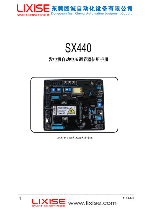
SX440發電机自動電壓調節器使用手冊1. 技術參數检测与检测与电源电源电源输入输入 电压 190 ~ 264 V AC 单相二线 电压建立 在A VR 输入端子需剩磁电压5 V AC 以上频率 50/60 Hz 以跨接铜片设定 消耗功率 最大12 Watt输 出 电压 207 V AC 输入时 最大90 VDC 低频保护 出厂预设:95% Hz 电流 连续4A ,非连续为10秒内10A 斜率:下降至30 Hz 时为170%电阻 最小15 Ohm电压修正 最大输入:±5 VDC调压精度 < ±1% (发动机转速变动在4%内) (模拟输入) 灵敏度:每1VDC 可调节5%发电机电压 温差稳定度 每℃变化,电压漂移0.05%输入电阻:1K Ohm 外部电压调节 用1K Ohms 1 Watt 电位器时为±8% 电流补偿 负 载:10 Ohm电压缓慢建立时间 2秒尺 寸 150mm L * 135mm W * 40mm H DROOP 无功调差 最高灵敏度0.07A 对应5%压降(PF=0时) 重 量 418公克 ± 2%最大输入0.33A2. 接線2.1 K1、K2:为磁场开关,不使用时须短路跨接. 2.2 P2、P3:为磁场电源输入端子. 2.3 3、2:为检测电源输入端子.2.4 1、2:为外接VR ,不使用时须短路跨接. 2.5 、 : 磁场+端、 磁场−端. 2.6 S1、S2:DROOP CT 输入端.2.7 A1、A2:V AR / PF 控制输入(V / TRIM). 2.8 AB 、C :90KW 以下 A 、C 跨接,90KW~ 550KW B 、C 跨接,550KW 以上 A 、B 跨接. 2.9 J1 ~ J8:选择跨接线2-3、4-5、6-7. (如图二) 2.10 建议使用一较高遮断容量之保险加装于励磁场电源,熔丝容量须依实际满载励磁场电流的120%.注意!! 熔丝熔丝加装位置须能有效切断励磁加装位置须能有效切断励磁场回路场回路,,且勿与励磁场串接.3. 調節3.1 低频调节 (U/F).3.1.1 在50Hz 使用时,将 “跨接线” 插于COM 与50Hz 之间,在60Hz 使用时,将“跨接线” 插于COM 与60Hz 之间. 3.1.2 U/F 旋钮为设定低频保护之频率拐点值,其设定步骤为:(1) 使发动机启动,且电压建立.(2) 调节发动机转速至所须之低频值.(3) 缓慢调节U/F 旋钮,使低频保护红色LED 灯亮起即可 (出厂预设50Hz 时45Hz 、60Hz 时55Hz)。
- 1、下载文档前请自行甄别文档内容的完整性,平台不提供额外的编辑、内容补充、找答案等附加服务。
- 2、"仅部分预览"的文档,不可在线预览部分如存在完整性等问题,可反馈申请退款(可完整预览的文档不适用该条件!)。
- 3、如文档侵犯您的权益,请联系客服反馈,我们会尽快为您处理(人工客服工作时间:9:00-18:30)。
HWLT-4型微机励磁调节器说明书哈尔滨电机厂有限责任公司控制设备事业部二零零一年二月目录1总体介绍1.1基本工作原理及技术特点1.2主要技术指标及参数2硬件介绍2.1组成特点2.2具体配置2.3接口信息3软件介绍3.1实时控制系统3.1.1控制器3.1.2跟随器3.1.3监控器3.2操控监视系统3.2.1性能概述3.2.2主控显示屏3.2.3系统参数设置屏3.2.4系统状态监视屏3.2.5故障分析显示屏3.2.6系统数据追忆及曲线分析屏3.2.7曲线参数设置4人机接口单元4.1串形通讯4.2并行通讯5文件及培训6使用条件7质量保证8附录1总体介绍1.1基本工作原理及技术特点图1.1 励磁系统原理框图由本调节器组成的自并励系统原理图见图1.1。
HWLT-4型微机励磁调节器是哈尔滨电机有限责任公司控制设备事业部的新一代产品,它是在前几代产品的基础上、应用国内外的先进技术、把握现代励磁的发展方向所完成的,提高了发电机运行的自动化程度。
该调节器采用标准化设计,扩展性强,升级方便,可以根据具体用户的要求改变或增加功能模块,是我公司为大中型同步电机配套的主导产品。
HWLT-4型微机励磁调节器由两套独立的微机通道和一套独立的模拟通道组成,每个微机通道分为两个环:电压环和电流环,模拟通道为电流环。
电压环是取发电机端电压信号进行闭环的,亦称为自动环;电流环是取转子电流信号进行闭环的,亦称为手动环。
控制通道根据现场工况,进行实时控制、准确调节。
为保证调节的快速性,系统连续采样,在一个工频周期内完成各种运算。
包括PID运算,以及各种限制、保护的判断,并完成各种控制信号的输出。
其中操作回路的动作由工业控制机与继电器共同控制完成。
本调节器具有极强的冗余容错能力,运行可靠,平均无故障工作时间大大加长。
两套微机通道与模拟通道,在正常情况下同时运行,但只有一套处于在线状态,能够发出控制信号;其它通道则处于离线热备用状态,其给定值、在线参数、控制信号均处于跟踪工作状态。
在线通道一旦故障,发出的控制信号将被闭锁,转为离线通道;离线通道自动投入,发出控制信号,转为在线通道。
当两套微机通道均出现故障时,模拟通道自动投入。
本调节器具有如下特点:可靠性高。
本调节器硬件抗干扰性强,适合于在强电磁场干扰下的电厂运行。
其组成模块化、标准化,调试简单、维护方便。
功能强大。
本调节器通用性强,适用于各种大、中型同步发电机的可控硅励磁;软件丰富,具有完备的辅助调节和自诊断功能;灵活性大,可根据用户的不同要求,通过修改软件实现。
跟踪精确。
微机通道之间,微机通道的环与环之间,微机通道与模拟通道之间,相互跟踪,均可实现无扰动切换。
微机通道可在线修改参数,跟踪使两套微机通道协调一致。
采用数字给定。
给定方式有二种:数字输入或开关输入。
给定的速度及上、下限均可人为设置,给定平滑、精度高。
完善的人机接口及操作回路。
具备极强的人机对话能力,包括与上位计算机的通讯。
操作简单,能够在主控室及现场完成对调节器的控制,并对多点进行监测,可靠性大大提高。
1.2主要技术指标及参数满足国家标准《GB/T 7409-1997 同步电机励磁系统》的技术要求,并在某些方面优于该标准。
具体数据如下:晶闸管控制角α的移相范围:0~180度晶闸管控制角α的分辨率:0.043度/位码CPU:80486 DX4-100A/D转换:单端16路(差分8路)输入,分辨率12位。
D/A转换:4路,分辨率12位。
DI:32路开关量输入,光电隔离型。
DO:32路开关量输出,光电隔离型。
调节频率:100次/秒。
调压范围:10%-110%。
调压精度:±0.5%。
附加调差:±15%内任选,级差0.1%。
频率特性:频率每变化±1%,发电机端电压变化小于额定值的±0.25%。
自动零起升压:升压时间4秒,2%残压可靠起励,超调小于5%。
±10%阶跃响应:超调量小于阶跃量的30%,振荡次数小于3次,调节时间小于10秒。
发电机电压调整速率:可调,不小于每秒0.3%,不大于每秒1.0%。
调节器输入电气量:发电机定子电压:额定值100V,3相。
发电机定子电流:额定值5A,3相。
系统电压:额定值100V,3相。
励磁电压:额定值按实测值给定。
转子电流:额定值按实测值给定。
脉冲输出参数:六相双脉冲触发、脉宽400μs,可触发2200A及以下的晶闸管。
2硬件介绍 2.1组成特点2.1.1采用ADVANTECH ®的MIC-2000工业控制计算机面向工业过程实时控制设计,抗干扰性强 Intel 32位处理器做信息处理,实时快速 Flash 电子盘做信息存储,安全可靠开放式、模块化结构,维护简单,升级方便 2.1.2采用PPC-102S 平板电脑作为人机接口单元彩色液晶显示,实时提供现场工况 触摸屏式输入,在线调整控制参数 故障信息自动存储 过程数据信息记忆PPC-102S 平板电脑由台湾ADVANTECH ®公司生产,作为工业现场的智能监控设备。
2.1.3先进的冗余容错结构灵活配置各种冗余容错结构 智能思维判断,超强纠错功能容错是提高微机控制系统可靠性的主要技术之一。
容错系统根据容错方式可分为静态冗余(屏蔽冗余)容错系统和动态冗余(备用冗余)容错系统两大类。
静态冗余容错系统的典型应用为三模冗余表决系统(TMR)。
它对错误处理的基本方法是纠错、少数服从多数表决,如图2.1所示。
图2.1 TMR 容错系统动态冗余容错系统中,模块被分为在线模块和备用模块,由在线模块完成规定的功能,备用模块做为热备用或冷备用。
当在线模块失效时将被切除,备用模块转为在线模块。
最基本的动态冗余容错系统为二模冗余容错系统,如图2.2所示。
切换开关图2.2 二模冗余容错系统HWLT-4型励磁调节器综合静态冗余容错系统和动态冗余容错模块1 模块2系统的特点,采用了混合冗余容错技术,在硬件上可灵活构成双通道混合冗余容错系统和三通道混合冗余容错系统。
其构成方法是: 通道输入并联(同一信息可取自不同传感器)通道输出并联冗余通道间信息通讯接口对接输出开关互锁信号对接软件会自动识别冗余通道,进行信息交流与容错运行。
三通道混合冗余容错系统硬件示意结构如图2.3所示。
图2.3 三通道混合冗余容错励磁调节器从图中可以看出,该冗余容错系统由三个并行的功能模块组成,每个模块都具有独立完成系统功能的能力。
模块1与模块2具备相同的功能结构,为微机通道,通讯方式连接;模块3为模拟通道,通过跟踪与其它模块连接。
每个模块的功能如图2.4所示。
输出经独立控制的输出开关连到系统的输出端,输出开关由该模块的硬件监控器控制,输出开关之间设有互锁逻辑,保证在任一瞬间只能一个闭合。
图2.4 单模块功能硬件监控器监视本模块的运行情况,完成以下任务:掉电退出死机退出故障退出这种方式同静态冗余容错系统不同之处为每个模块在工作期间,不会进行“少数服从多数”的表决,而是将其它模块的信息作为提醒,执行对故障的智能诊断,避免由于“盲从”带来的系统故障。
这种方式同动态冗余容错系统不同之处为故障情况下在线模块自动退出,而不是自动切换,冗余模块根据情况判断是否能够接替工作、转为在线模块。
它能够有效地避免由于切换带来的不可靠因素,并对故障进行快速处理。
2.1.4高可靠性电源采用两台发电厂专用开关电源并联为调节器提供±24V DC电源。
每台电源由交流和直流两路并联输入,它们分别来自三种独立电源:厂用电220V AC自用电220V AC厂用电220V DC2.1.5输出多级闭锁为了防止模块之间的输出信号互相干扰,除了使用硬件监控器逻辑闭锁以外,输出级还具有更可靠的隔离措施。
2.2 具体配置2.2.1核心硬件及特点MIC-2000/11工控机箱开关电源+24V/ 150W运行温度0℃~40℃平均无故障时间25,000小时以上MIC-2340中央处理单元(CPU)CPU 80486 DX4-100,32M 内存2个串行口,1个并行口MIC-2718模拟量输入(AI)12位A/D转换器,转换时间10 us硬件触发,1K FIF0 缓存MIC-2728模拟量输出(AO)12位D/A 转换器,建立时间小于60us隔离电压大于500 V DCMIC-2730开关量输入(DI)输入电压0~30 V DC,隔离电压2500 V DC发光二极管指示每路信息MIC-2750开关量输出(DO)输出电压5~40 V DC,隔离电压2500 V DC发光二极管指示每路信息PCM-3820电子盘PC-104 总线标准4M容量FlashHEC-01计数定时及监控测频率测相位硬件监控2.2.2外围模块输入信号调理模块机端电压调理机端电流调理频率调理相位调理励磁电压调理励磁电流调理磁场电压调理磁场电流调理电网电压调理模拟手动通道及脉冲发生器模块FCR运行方式,数字给定,数字跟随微机通道 脉冲发生器(双脉冲输出),含脉冲输出闭锁脉冲功率放大及隔离模块脉冲功率放大,输出至脉冲变脉冲丢失报警,脉冲输出闭锁2.3 接口信息2.3.1输入信息模拟量输入发电机端电压发电机端电流A/FCR控制电压励磁电流励磁电压磁场电流磁场电压系统电压机组频率功率因数开关量输入磁场开关状态发电机开关状态各控制通道运行状态(多路)整流装置运行状态(多路)远方控制信号(多路)故障复位2.3.2输出信息模拟量输出控制电压开关量输出起励控制信号磁场开关操作信号整流装置工作信号(多路)限制动作、故障报警信号运行状态远方指示信号(多路)2.3.3数字通讯信息微机通道间信息交换微机通道与智能监控系统信息交换 调节器与手提电脑信息交换调节器与遥控系统信息交换维护整定信息3软件介绍3.1实时控制系统工业控制微机的飞速发展,为精确地实现各种复杂的算法和先进的功能提供了可能性。
HWLT-4型同步发电机微机励磁调节器成功地采用了高可靠智能控制策略,它主要包括控制器、跟随器和监控器三个部分,如图3.1所示。
图3.1同步发电机励磁系统示意图3.1.1控制器高可靠智能励磁调节器的控制器如图3.2所示,它覆盖了现代励磁系统所需要的各种控制功能。
根据控制器的主要功能,从以下几个方面加以介绍:3.1.1.1控制方式(Control mode)本调节器包含四种控制方式:自动电压调节AVR(Automatic Voltage Regulation)AVR控制方式为常规调节模式,它以机端电压作为反馈量进行闭环调节。
对于自并励励磁系统,采用PI控制算法;对于三机励磁系统,引入转子电流微分负反馈,以提高励磁系统的稳定性,采用PID控制算法。
图3.2 励磁调节器控制器示意图在AVR控制方式下,调节器具有如下功能:●为了加快同期并网速度,可选择系统电压跟踪功能。
