研华数据采集卡PCI-1610A_1610B_1610CU_DS_CHS
NI数据采集选型

更多内容请访问DAQ事业部官方网站:
东北地区(黑龙江、吉林、辽宁) 销售电话:010-54012121-323 客服电话:010-82600055-617
华北地区(北京、天津、河北) 销售电话:010-82600055-691/628 客服电话:010-82600055-617
华南地区(深圳、广东、福建、海南) 销售电话:021-54012121-322 客服电话:021-54012121-336
R系列 智能DAQ
模拟输出卡
数字I/O卡
计数器/定时器
无线和以太网数据采集设备
CompactDAQ-USB数据采集平台
2
CompactDAQ模块
31
2
2
CompactDAQ机箱
32
3
3
CompactDAQ附件
33
3
4
SCC — 便携式信号调理设备
4
5
SCC信号调理模块
35
SCC外盒
36
6
镶板
37
7
数据采集软件解决方案
3、发货流程:合同签订后,客服人员根据合同条款及 时处理并安排发货。
4、开票流程:根据合同条款,客服人员会及时与您联 系并确认开票事宜。选择DAQ事业部,让您放心省心。
板卡暂借服务
已经购买了DAQ卡,但是因为供货周期的问题让眼前测 试测量工程被迫搁置等待;由于长期使用导致数采卡的精准 性出现问题而正进行校准或维修;OEM用户在批量购买数采 卡前想先试用一段时间,来确定板卡能否满足自己的测试测 量需求等等。
台湾研华电气查询表

价格 2000 2000 2400 2900 2500 2000 2200 2600 3000 3000
备注
11 PCA-6186VE 12 PCA-6187 13 PCA-6188 14 序号 1 2 3 4 5 6 7 8 9 10 型号 PCI-1710 PCI-1710HG PCI-1710L PCI-1711 PCI-1711L PCI-1713 PCI-1712 PCI-1716 PCI-1716L PCI-1714
台湾研华系列PC总线工业控制产品系列
研华原装整机
序号 型号 描述 1 研华IPC-610H-PIII 6003V/PIII 1G/256M/80G/1.44M/52XCD/KB/MOUSE/USB 2 研华 PIC-610H-PIV 6006LV/P4 2.8G/512M/80G/1.44M/52XCD/KB/MOUSE/USB 3 研华 PIC-610H-PIV 6007LV/P4 3.0G/1G/160G/1.44M/52XCD/KB/MOUSE/USB 4 价格 6800 8600 9600 备注
平板电脑及键盘
描述 12" 彩色TFT LCD显示的平板PC、PIII500、64M、20G、触摸屏 15" 彩色TFT LCD显示的平板PC、PIII500、64M、20G、触摸屏 104键工业键盘 105键抽屉键盘 105键19"机柜抽屉键盘 价格 15000 20000 500 2400 3250 备注
工业级液晶屏
型号 FPM-3120 FPM-3150 FPM-3175 FPM-3190 描述 12“TFT 15“TFT 17“TFT 19“TFT 价格 8750 12910 25000 35500 备注
USB数据采集卡的使用流程 (2)

USB数据采集卡的使用流程1. 引言USB数据采集卡是一种常用的设备,用于连接计算机与外部传感器、仪器等设备,将采集到的数据传输给计算机进行处理和分析。
本文将介绍USB数据采集卡的使用流程。
2. 准备工作在使用USB数据采集卡之前,需要进行一些准备工作,主要包括: - 确定所需采集的数据类型和频率,以便选择合适的USB数据采集卡。
- 下载并安装USB数据采集卡的驱动程序,确保能够正常连接并识别设备。
- 准备相应的传感器、仪器等设备,确保能够接入USB数据采集卡。
3. 连接USB数据采集卡连接USB数据采集卡需要按照以下步骤进行: 1. 将USB数据采集卡插入计算机的USB接口。
2. 等待计算机自动识别设备并安装驱动程序。
如果计算机没有自动安装驱动程序,可以手动安装,通常可以从USB数据采集卡的官方网站或光盘中获取驱动程序。
3. 检查USB数据采集卡的连接状态,确保设备正确连接到计算机。
4. 配置软件设置配置USB数据采集卡的软件设置需要按照以下步骤进行: 1. 打开USB数据采集卡的软件界面,通常可以从桌面上的快捷方式或开始菜单中找到。
2. 在软件界面中选择相应的数据采集卡设备,确保与实际连接的设备对应。
3. 根据所需的数据类型和频率,设置数据采集的参数,例如采样率、增益等。
4. 配置数据存储位置和文件格式,可以选择保存为文本文件、CSV文件或其他格式。
5. 检查软件设置是否正确,确保能够正常采集数据。
5. 数据采集进行数据采集需要按照以下步骤进行: 1. 确保所有设备连接正常,传感器或仪器的信号源正确接入到USB数据采集卡。
2. 点击软件界面上的开始采集按钮,开始采集数据。
3. 观察数据采集的过程,确保数据的准确性和稳定性。
4. 在需要暂停或停止采集时,点击软件界面上的相应按钮进行操作。
5. 保存采集到的数据到指定的文件位置,以便后续处理和分析。
6. 数据处理和分析采集到的数据可以通过一些数据处理和分析软件进行进一步的处理和分析,常见的软件包括Matlab、Python等。
ICP DAS M-7053D 16通道数字输入数据采集模块快速入门指南说明书
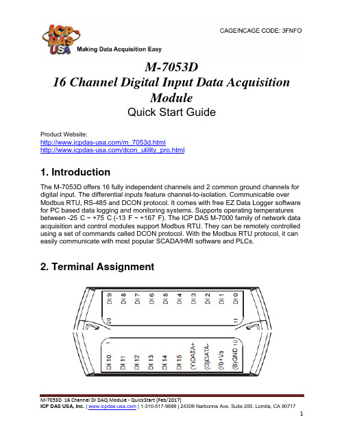
M-7053D16 Channel Digital Input Data AcquisitionModuleQuick Start GuideProduct Website:/m_7053d.html/dcon_utility_pro.html1. IntroductionThe M-7053D offers 16 fully independent channels and 2 common ground channels for digital input. The differential inputs feature channel-to-isolation. Communicable over Modbus RTU, RS-485 and DCON protocol. It comes with free EZ Data Logger software for PC based data logging and monitoring systems. Supports operating temperatures between -25°C ~ +75°C (-13°F ~ +167°F). The ICP DAS M-7000 family of network data acquisition and control modules support Modbus RTU. They can be remotely controlled using a set of commands called DCON protocol. With the Modbus RTU protocol, it can easily communicate with most popular SCADA/HMI software and PLCs.2. Terminal AssignmentM-7053D 16 Channel DI DAQ Module - QuickStart (Feb/2017)3. Block/ Wiring Diagram4. Default SettingsDefault settings for the M-7053D module is:。
研华数据采集卡PCI-1快速入门手册
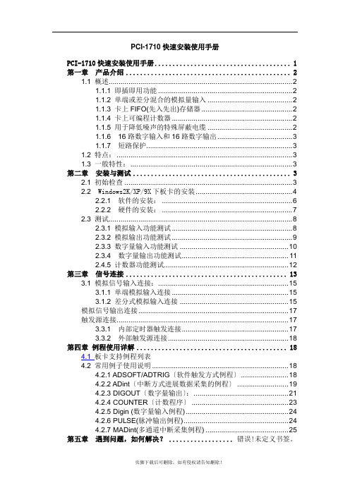
PCI-1710快速安装使用手册PCI-1710快速安装使用手册 (1)第一章产品介绍 (2)1.1 概述 (2)1.1.1 即插即用功能 (2)1.1.2 单端或差分混合的模拟量输入 (2)1.1.3 卡上FIFO(先入先出)存储器 (2)1.1.4 卡上可编程计数器 (2)1.1.5 用于降低噪声的特殊屏蔽电缆 (2)1.1.6 16路数字输入和16路数字输出 (3)1.1.7 短路保护 (3)1.2 特点: (3)1.3 一般特性: (3)第二章安装与测试 (3)2.1 初始检查 (3)2.2 Windows2K/XP/9X下板卡的安装 (4)2.2.1 软件的安装: (6)2.2.2 硬件的安装: (7)2.3 测试 (8)2.3.1 模拟输入功能测试 (8)2.3.2 模拟输出功能测试 (9)2.3.3 数字量输入功能测试 (10)2.3.4 数字量输出功能测试 (11)2.4.5 计数器功能测试 (12)第三章信号连接 (13)3.1 模拟信号输入连接: (15)3.1.1 单端模拟输入连接 (15)3.1.2 差分式模拟输入连接 (15)模拟信号输出连接 (17)触发源连接 (17)3.3.1 内部定时器触发连接 (17)3.3.2 外部触发源连接 (18)第四章例程使用详解 (18)4.1 板卡支持例程列表4.2 常用例子使用说明 (18)4.2.1 ADSOFT/ADTRIG〔软件触发方式例程〕 (18)4.2.2 ADint〔中断方式进展数据采集的例程〕 (19)4.2.3 DIGOUT〔数字量输出〕: (21)4.2.4 COUNTER〔计数程序〕 (23)4.2.5 Digin (数字量输入例程) (24)4.2.6 PULSE(脉冲输出例程) (24)4.2.7 MADint(多通道中断采集例程) (25)第五章遇到问题,如何解决? .................. 错误!未定义书签。
PIC16F193X 194X微控器高性能与行业领先的低功耗微控技术说明书

PIC16F193X/194X Microcontrollers Advanced Performance & Integration with Industry Leading Low PowerM i c r o chi p T e c h n o l o g y I n c o r p o r a t e dSummaryAs the demand for sophistication in consumer and embedded products continues to expand, so does the need for 8-bit microcontrollers that can meet the design challenges this creates. This requires microcontrollers that provide increased performance, maximum integration, and the lowest power – the PIC16F193X/194X family does just that.Based on the 8-bit Enhanced Mid-Range core, thePIC16F193X/194X microcontrollers have a total of 49 instructions to optimize program code and data handling, while increasing effi ciency and reducing clock cycles. The PIC16F193X/194X provide up to 28 KB of Flash program memory and numerous enhanced capabilities inclusive of; 16 level hardware stack, up to 1 KB data memory, low power 1.8V operation, nanoWatt XLP, 32 MHz internal oscillator, up to 2x SPI/I2C™ & UART, up to 17 channels 10-bit ADC, up to 5 (E)CCP, 2x comparators, integratedmTouch™ and LCD control.The on-chip LCD drive supports up to 184 segments and provides a low-power drive mode for lower power and increased effi ciency. In addition, there are up to 5 Pulse Width Modulation (PWM) channels with independent time bases for controlling various motor types, LED’s, and peripherals.“LF” family members feature Microchip’s nanoWatt XLP Technology – for extreme Low Power consumption – enabling designs to achieve world-leading battery lifetime. These new MCUs feature active currents down to50 μA/MHz and sleep currents down to 60 nA and sets the industry benchmark for low-power and peripheral integration. All of these general-purpose MCUs are well suited fora multitude of applications in the appliance, consumer, industrial and automotive markets, among others.Key Features■U p to 28 KB of Flash Program Memory■Up to 1 KB of Data Memory■256 bytes of High Endurance Data EEPROM■32 MHz internal oscillator■Integrated LCD Control with up to 184 segments■I ntegrated mTouch Capacitive Sensing Module■Up to (17) 10-bit ADC channels ■U p to 3 comparators with Rail-to-Rail input and 555 timer functionality■U p to 2 each: Master SPI/I2C and EUSART support for RS-232/RS-485, as well as LIN support■5-bit DAC providing 32 level voltage reference– Easily implemented as a low voltage detect■U p to 3 Enhanced and 2 Capture Compare PWM peripherals with independent time base■L ow Power ‘LF’ Variants with XLP Technology– Dynamic currents down to 50 μA/MHz– Sleep currents of 60 nA– Watchdog Timer (WDT) current of 500 nA– Low-power 32 kHz Timer1 oscillator current of 600 nA ■1.8V operation up to 5.5V– Full analog operation throughout■16-level hardware stack, with overfl ow/underfl ow interrupt ■4x8-bit and 1x16-bit timers, with eXtreme Low Power Real-Time Clock (RTC) support■R obust and reliable operational monitors, such as Power-On Reset (POR), Brown-out Reset (BOR) and low-power Watchdog Timer (WDT)PIC® microcontrollers with the Enhance Mid-Range core are denoted as PIC1X F1XXXLearn more at /enhanced and/F1Eval.Information subject to change. The Microchip name and logo, the Microchip logo, MPLAB and PIC are registered trademarks and mTouch, PICDEM and PICkit are trademarks of Microchip TechnologyIncorporated in the U.S.A. and other countries. All other trademarks mentioned herein are property of their respective companies. © 2010, Microchip Technology Incorporated. All Rights Reserved. Printed in the U.S.A. 8/10 DS41435A*DS41435A*Visit our web site for additional product information and to locate your local sales office.Microchip Technology Inc. • 2355 W. Chandler Blvd. • Chandler, AZ 85224-6199/enhanced /F1EvalPart Number Development Tool Part Number Development ToolDV164131PICkit™ 3 Debug Express(Coming Soon)F1 + Low Voltage Evaluation PlatformDV164035MPLAB ICD 3 In-Circuit Debugger Kit (Coming Soon)F1 BLDC Motor add-on for the F1 Evaluation Platform DM164130-1F1 Evaluation Platform/F1Eval (Coming Soon)F1 BDC Motor add-on for the F1 Evaluation PlatformDV164132F1 Evaluation Kit (Coming Soon)F1 Bipolar Stepper Motor add-on for the F1 Evaluation Platform DM183032PIC18 Explorer Board (Coming Soon)F1 Unipolar Stepper Motor add-on for the F1 Evaluation Platform DM163030PICDEM™ LCD 2 Demo Board(Coming Soon)PIC16F/LF1947 Plug-in Module(Accessory for the PIC18 Explorer or PICDEM LCD 2)Additional Information■ PIC16F/LF193X Data Sheet , DS41364■ PIC16F/LF194X Data Sheet , DS41414■ PIC1XF1XXX Software Migration , DS41375■ I 2C Bootloader for the PIC16F1XXX , AN1302■ mTouch™ Sensing Solution User’s Guide , DS41328■ 8-bit PIC Microcontroller Solution Brochure , DS39630■ Corporate Focus Product Selector Guide , DS01308■ Quick Guide to Microchip Development Tools Brochure ,DS51894Sample/Purchasing Information■ On-line Sampling: ■ On-line Purchasing: Device Flash (Bytes)Data RAM (Bytes)Data EEPROM (Bytes)LCD Segments 10-bit ADC ComparatorsECCP/CCP Communication Operating Voltage Pins Packages PIC16F1933 PIC16LF19337K 256256601123/2EUSART , I 2C, SPI 1.8V-5.5V 1.8V-3.6V 28SPDIP , SOIC, SSOP ,6X6 QFN, 4X4 UQFN PIC16F1934 PIC16LF19347K 256256961423/2EUSART , I 2C, SPI 1.8V-5.5V 1.8V-3.6V 40/44PDIP , TQFP , 8X8 QFN, 5X5 UQFN PIC16F1936 PIC16LF193614K 512256601123/2EUSART , I 2C, SPI 1.8V-5.5V 1.8V-3.6V 28SPDIP , SOIC, SSOP ,6X6 QFN, 4X4 UQFN PIC16F1937 PIC16LF193714K 512256961423/2EUSART , I 2C, SPI 1.8V-5.5V 1.8V-3.6V 40/44PDIP , TQFP , 8X8 QFN, 5X5 UQFN PIC16F1938 PIC16LF193828K 1024256601123/2EUSART , I 2C, SPI 1.8V-5.5V 1.8V-3.6V 28SPDIP , SOIC, SSOP ,6X6 QFN, 4X4 UQFN PIC16F1939 PIC16LF193928K 1024256961423/2EUSART , I 2C, SPI 1.8V-5.5V 1.8V-3.6V 40/44PDIP , TQFP , 8X8 QFN, 5X5 UQFN PIC16F1946 PIC16LF1946 14K 5122561841733/22x EUSART , 2x I 2C,2x SPI 1.8V-5.5V 1.8V-3.6V 64TQFP , 9X9 QFN PIC16F1947 PIC16LF194728K10242561841733/22x EUSART , 2x I 2C,2x SPI1.8V-5.5V 1.8V-3.6V64TQFP , 9X9 QFNAvailable in 28-, 44- & 64-pin packages.PIC16F193X/194X Block DiagramInternal Oscillator32 MHzData EEPROM256BData MemoryUp to 1 KB Linear AddressingEnhanced Mid-Range CPU14-bit Instruction49 Total Instructions(2) 16-bit File Select RegistersInterrupt Context SaveReliable Low PowerWDT, RTC, BOR, POR,nanoWatt XLPLCD Drive Up to 184 segments 10-bit ADC Up to 17 channelsUp to 3x Comparators with SR Latch mTouch™Capacitive Sensing ModuleCommunications Up to 2x each MI C, SPI, EUSARTCapture/Compare/PWMUp to 5 Channels16-Level Stack &Program CounterReset CapabilitiesProgram MemoryUp to 28 KB (16K Instructions)5-bit DAC 32-Level V。
基于组态王研华板的数据采集应用
基于组态王研华板的数据采集系统应用各种计算机测控系统中,PC插卡式是最基本最廉价的构成形式。
它充分利用了PC计算机的机箱、总线、电源及软件资源。
本章以研华(中国)公司生产的PCI-1710HG多功能数据采集卡为例,详细介绍数据采集卡的软、硬件安装过程,并以此为基础,对基于板卡的模拟量输入/输出、开关量输入/输出程序的设计过程进行详细的描述。
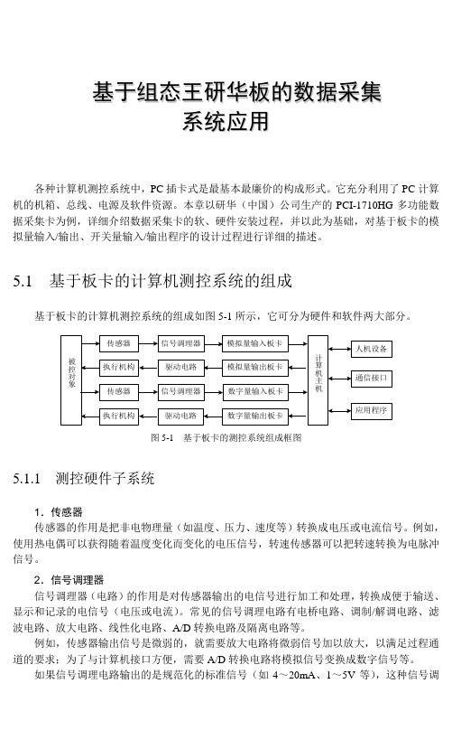
5.1 基于板卡的计算机测控系统的组成基于板卡的计算机测控系统的组成如图5-1所示,它可分为硬件和软件两大部分。
图5-1 基于板卡的测控系统组成框图5.1.1 测控硬件子系统1.传感器传感器的作用是把非电物理量(如温度、压力、速度等)转换成电压或电流信号。
例如,使用热电偶可以获得随着温度变化而变化的电压信号,转速传感器可以把转速转换为电脉冲信号。
2.信号调理器信号调理器(电路)的作用是对传感器输出的电信号进行加工和处理,转换成便于输送、显示和记录的电信号(电压或电流)。
常见的信号调理电路有电桥电路、调制/解调电路、滤波电路、放大电路、线性化电路、A/D转换电路及隔离电路等。
例如,传感器输出信号是微弱的,就需要放大电路将微弱信号加以放大,以满足过程通道的要求;为了与计算机接口方便,需要A/D转换电路将模拟信号变换成数字信号等。
如果信号调理电路输出的是规范化的标准信号(如4~20mA、1~5V等),这种信号调组态软件数据采集与串口通信测控应用实战理电路称为变送器。
在工业控制领域,常常将传感器与变送器做成一体,统称为变送器。
变送器输出的标准信号一般送往智能仪表或计算机系统。
3.输入输出板卡应用IPC对工业现场进行控制,首先要采集各种被测量,计算机对这些被测量进行一系列处理后,将结果数据输出。
计算机输出的数字量还必须转换成可对生产过程进行控制的量。
因此,构成一个工业控制系统,除了IPC主机外,还需要配备各种用途的I/O接口产品,即I/O板卡。
常用的I/O板卡包括模拟量输入/输出(AI/AO)板卡、数字量(开关量)输入/输出(DI/DO)板卡、脉冲量输入/输出板卡及混合功能的接口板卡等。
TP1608数据采集卡使用手册说明书

目录一、概述 (1)二、功能特点 (2)三、技术指标 (3)3.1.数据采样口 (3)3.2通讯接口 (3)3.3机械特性 (4)3.4电源要求 (4)3.5环境 (4)3.6认证资料 (4)四.安装与接线 (5)4.1模块安装 (5)五、通讯设置及通讯协议 (8)5.1ADVANTECH通信协议 (8)5.2MODBUS通信协议 (11)六、软件驱动的安装 (12)七、系统软件使用说明 (13)7.1系统概述 (13)7.2运行环境 (13)7.3软件安装 (13)7.4界面介绍 (14)7.5主菜单栏 (14)7.6工具栏 (14)7.7显示主窗口 (14)7.8建立设备和通讯设置 (15)7.9历史数据 (20)7.10系统退出 (23)八、故障分析与排除 (24)一、概述TP1608采集卡采用工业级双485和标准TPYE-C接口,1608外观时尚简约、小巧便携,可导轨安装。
主要应用于冶金、石油、化工、建材、造纸、食品、制药、热处理和水处理等各种工业现场。
多种功能测试(电压、电流、温度、湿度、压力、振动、频率、流量、液位)轻松实现数据采集、监控、记录、控制等。
本产品与电脑通讯配合上位机软件显示。
模块可以接收多种类型的电流、电压和电阻信号,实现温度、湿度、压力、液位、流量、成分以及力、力矩、位移等物理量的显示、记录、越限监控、报表生成、数据通讯、信号变送以及流量累计等功能。
二、功能特点●本产品显示信息量大、界面友好、操作简单,以下是主要功能及特点:采集卡内部嵌入20种类型信号采集,一个模块即可解决市面上大部分模拟信号采样,类型自由切换,只需一个采集卡就可完成温度、湿度、压力、流量、电压、电流、振动、光照等信号的采集工作●双485口,标准TPYE-C接口,多种协议选择,更好的为您所用,采集卡支持三种协议:modbus-rtu协议、研华Adam4017协议、主动上报协议●完美的隔离保护,更放心、安全的数据采集;电源与通道之间耐压3000VAC(50/60HZ),通道与通道之间400VAC(50/60HZ),380V交直流带电测试,无需做绝缘保护,采集口最大承受电压±15V。
5-研华输入输出采集卡信号类型详解

研华输入输出采集卡信号类型详解一、输入输出信号类型 (3)二、模拟量输入详解 (4)2.1模拟量输入方式 (4)2.2 模拟量数据传输方式 (4)2.2.1 软件轮询传输: (4)2.2.2 (4)2.2.3 DMA (Direct Memory Access) 传输(部分板卡支持)、 (5)2.3 模拟量输入参数详解 (5)2.3.1 采样频率 (5)2.3.2 分辨率 (5)2.3.3 精度 (6)三、模拟量输出详解 (7)3.1 模拟量输出方式 (7)3.2模拟量输出数据传输方式 (7)3.2.1软件轮询传输 (7)3.2.2 DMA传输(部分板卡支持) (7)四.数字量输入详解 (8)4.1 TTL输入、干湿接点输入 (8)4.2隔离输入 (8)五.数字量输出详解 (9)5.1 TTL输出 (9)5.2隔离输出 (9)5.3源电流和汇电流输出 (10)5.4 继电器输出 (11)一、输入输出信号类型研华输入输出采集卡,根据信号类型分类如下几种:1、模拟量输入 AI2、模拟量输出 AO3、数字量输入 DI4、数字量输出 DO下图使用图示展示,各数据类型的转换方式:二、模拟量输入详解2.1模拟量输入方式1、单端:所有信号的电压参考是对同一个GND2、差分:每个信号有自己独立的参考GND2.2模拟量数据传输方式2.2.1 软件轮询传输:1、客户应用程序操作2、采样频率不固定,以当前系统下最大的采样频率采集2.2.2 中断传输: (部分板卡支持)1、操作系统后台操作2、采集定量数据后触发CPU中断,传输数据2.2.3 DMA (Direct Memory Access) 传输(部分板卡支持)、1、操作系统后台操作2、直接内存存储数据2.3 模拟量输入参数详解模拟量采集有几个重要的参数,以下详细介绍每个参数的含义2.3.1 采样频率即每秒钟采集点数 Hz/S 。
采样频率越高,采样越逼真,否则会有失真情况。
北京新超仁达数据采集卡产品型录
配套端子板 ADAM-3937 P-500 P-800 P-510 P-512 PCLD-789D
DB-37 针孔型接口接线端子 带 1 个 40 针排线接插件和一个 37 针 D-sub 插针通用端子板 带 16 路继电器输出通用端子板 带 8 路隔离数字量输入端子板 带 8 路隔离数字量输出端子板 放大及多路选通板
概述 PCL-812PG 是为 IBM 或其他兼容计算机设计的一款高性能、高速多功能数据采集卡。
PCL-812PG 具备所有数据采集卡的功能,例如,A/D ,D/A 转换,DIO 和定时/计数器,本 卡的高规格使其在需要高速采集的情况下得到广泛应用。PCL-812PG 为低电平输入(例如, 热耦合信号测量)提供专门的高增益可编程仪表放大器。
订货信息 PCL-711B
8 路 12 位 50KS /s 高性价比多功能数据采集
新超控制
3/65
ISA 总线(多功能)
PC-1204 ISA 总线 AD,DA,DIO,脉冲计数/定时中断多功能综合板
特性: AD 输入通道:12 位 100KHz ,*单端 16 路/差分 8 路 AD 输入量程:单极性:0~5V,0~10V* 双极性:±2.5V,±5V,±10V 输入阻抗:>10MΩ;转换误差:<0.20% 输出码制:单极性为二进制原码 双极性为二进制偏移码 工作方式:软件查询、中断 最大差动输入值:20V 输出通道:12 位独立 4 路 输出信号范围: 电压方式:0~5V;0~10V*;±5V;±10V 电流方式:4~20mA 输出阻抗:≤2Ω D/A 转换码制:二进制原码(单极性) 二进制偏移码(双极性) D/A 转换时间:≤1μs D/A 转换综合误差: 电压方式:≤0.2﹪ FSR 电流方式:≤1﹪ FSR 电压输出方式负载能力:5mA/每路 16 路 TTL 电平开关量输入、输出 输出带锁存,输出电流≤2mA
DEWESoft数据采集产品样本

3
公
司
Dewesoft 掌握完整的仪器设计、 开发、 制造、 销售和市场 推广 ... 所有工作集于一身。
Dewesoft公司成立于2000年,今天, Dewesoft 产品已被 世界行业巨头应用于很多的测试领域。 Dewesoft公司将 自己定义为全球市场软硬件的革新者。从销售到技术支 持,通过与客户的紧密联系和支持,我们赢得了客户的 信任。
PCI-1711_user_manual中文版用户手册

3.2
I/O 接口 .......................................................16
3.2.1 针脚定义 ................................................16
图 3.1: PCI-1711/1731 的 I/O 接口针脚定义 ..............17
3.5.2 外部脉冲触发源连接 ......................................20
3.6
现场接线注意事项 ............................................... 21
第 4 章 软件概述 .............................. 23
图 2.1: 研华自动化软件安装界面.........................9
图 2.2: 研华自动化软件 - 分组选择.......................9
图 2.3: 研华自动化软件 - 安装选项......................10
图 2.4: 研华自动化软件 - 驱动按总线列表................10
A.1
模拟量输入 .................................................... 32
A.2
模拟量输出 (仅适用于 PCI-1711) ............................... 32
A.3
数字量输入 / 输出 .............................................. 33
5.4
DS1610软件说明书-v2
DS1610软件说明书v21客户端1.1安装运行DS1610Install.msi就可进入到DS1610客户端软件安装程序,并根据软件的提示进行安装。
软件安装完成后会自动运行自诊断程序,自诊断程序会自动检测软件的运行环境,如果运行环境有问题软件会有相应的提示,大多数情况下,问题的原因都在客户端的连接服务器IP设置上存在问题。
1.2运行运行桌面上的“DS1610客户端”或运行开始菜单中的“开始->程序->DS1610客户端->DS1610客户端”就可以进入到DS1610客户端软件中。
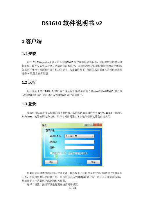
1.3登录登录时可以选择可以使用的服务器列表,系统默认的超级管理员ID为:admin,普通用户为user,初始密码均为123。
用户名或密码连续3次输入错误软件会自动关闭。
如果是因网络连接的问题而登录失败,软件提供了脱机登录的方式,即选中“暂时脱机工作,连接可用时自动联机”后,可以直接进入到DS1610客户端,由于未连接到服务器,只能查看上一次联机下载到的相关数据。
选择“设置”按钮可以进行更详细的网络设置。
1.4反向功能反向功能需要反向监控设备的支持,在DS1610的客户端上选择一个反向监控卡的端口后,就可以使用相应的反向功能,包括频谱测量、远程监控、合格线设置、历史记录查询等。
1.4.1反向频谱运行反向频谱功能,需要选择一个反向监控卡的端口,在反向功能面板上选择“频谱”按钮,或在端口上使用右键菜单运行。
1.4.2反向监控运行反向监控功能,需要选择一个反向监控卡的端口,在反向功能面板上选择“远程监控”按钮,或在端口上使用右键菜单运行。
反向监控分为2D频谱监控和3D频谱监控两种模式,2D频谱监控和频谱测量程序基本相同,可以将频谱的各项参数设置为监控计划,支持批量设置。
而3D监控可以同时查看多个端口的监控频谱。
1.4.3合格线设置运行合格线设置功能,需要选择一个反向监控卡的端口,在反向功能面板上选择“合格线”按钮,或在端口上使用右键菜+单运行。
DS1610宽带网络监控系统

模块型号 模块名称 主要功能
DS1610 (主机)
主要技术参数
方式
备注
7U标准机箱,16插槽,支持所有功能插卡热插拔,支持公 安装于前端 通过服务器实现 系统主机 网联网监测,24小时记录、预警、报警、录像、查询、分 2008年发布 或主结点 多机组网 析、诊断,保存一年监测数据。
监测回传通 5M~65M,50dB监测动态,8路英制F头监测端口,最小瞬发信 回传实时频 DS1610-1/F 道噪声与干 号捕获能力<1ms,18dBμ V~110dBμ V检测范围,±1.5dB精 1-16块用户自选 2008年发布 谱卡 扰 度,DS16101F支持双向测试功能。 5~50dB监测动态,4路英制F头监测端口, 经济型下行 监测下行通 20dBμ V~120dBμ V检测范围,±1.5dB精度;支持模拟、数 DS1610-3A 1-16块用户自选 2009年发布 前端监测卡 道前端性能 字电视全部制式。 MER>38dB,BER RS前/后 2E-3~1E-9,星座图。 5~ 70dB监测动态,4路英制F头监测端口, 15dBμ V~120dBμ V检测范围,±1.0dB精度;支持模拟、数 监测验证下 下行前端频 字电视全部制式。MER>40dB,BER RS前/后 2E-3~1E-9。 DS1610-3B 行通道前端 1-16块用户自选 2009年发布 谱监测卡 支持标准频谱仪功能, CSO/CTB,C/N,HUM功能,星座图分 性能 析,调制器检验。 可加装DMB-T 、CMMB、ISDB-T测试选件 DS1615 可与DS及DS2500R组成双向测试系统 FSK下行发 HFC双向网 正向扫描信号源:47MHz~1000MHz 100KHz 步进; 射机 络建设 60dBμ V~110dBμ V,1dB步进(可选)。 1U 2009年末发布
usb数据采集卡USB6202使用说明书
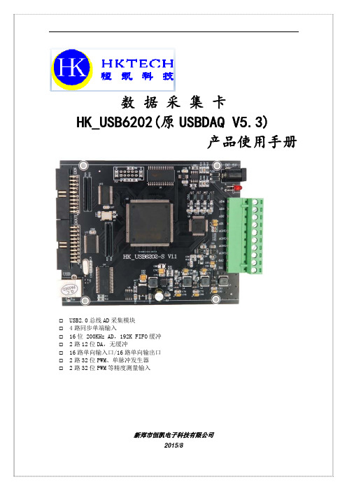
数据采集卡 HK_USB6202(原 USBDAQ V5.3)
产品使用手册
USB2.0 总线 AD 采集模块 4 路同步单端输入 16 位 200KHz AD,192K FIFO 缓冲 2 路 12 位 DA,无缓冲 16 路单向输入口/16 路单向输出口 2 路 32 位 PWM、单脉冲发生器 2 路 32 位 PWM 等精度测量输入
数据采集软硬件解决方案
DAQ 事业部将精心为您提供:
● 专业的售前咨询服务: DAQ 事业部工程师将根据您的测试要求以及预算为您度身 定制软硬件测试解决方案。 ● 完善的售后支持服务: DAQ 事业部将为您提供专家级的售后技术支持以及产品售 后质量保证服务。 ● NI 数据采集卡批量折扣支持 为 OEM 用户提供购买 NI 数据采集卡批量折扣优惠。 ● NI 数据采集卡租借服务 为 OEM 用户提供 NI 数据采集卡租借服务,降低 OEM 用户 前期研发成本。 ● 产品增值服务 为OEM用户提供产品增值服务,协助OEM更快推出新产品。 ● 培训课程服务 DAQ 事业部为使用 Visual Basic,Visual C++,Visual 的工程师提供 NI Measurement Studio 软件收 费培训课程服务,并为学员授予 DAQ 事业部与 NI 联合认 证的专业培训证书。
2006 年 5 月 8 日 DAQ 事业部推出全新 EaziDAQ 数据记 录软件,该软件是专为使用 NI 数据采集卡的用户提供的功 能强大、方便易用的数据记录软件。使用 EaziDAQ 数据记 录软件不仅可以获得实时的波形显示,更可以方便地进行数 据记录以及历史数据的动态回放等操作。
EaziDAQ 数据记录软件能够为您提供:
测量与自动化软件 DAQ 事业部软件产品(EaziDAQ 数据记录软件)............ 33
PCI 总线 PCI 总线(M 系列多功能数据采集产品)........................ 10 PCI 总线(S 系列同步多功能数据采集产品).................. 18 PCI 总线(数字 I/O 产品)................................................ 19 PCI 总线(计时器 / 定时器产品)..................................... 24 PCI 总线(模拟输出产品)............................................... 26
PCIe采集卡使用手册说明书

03安全性须知04硬件安装05驱动安装07属性07设备信息09时序13OSD14HDMI15视频18输入26输出格式26Video Crossbar 目录2安全性须知电气方面的安全性操作方面的安全性为避免可能的电击造成严重损害,在搬动计算机主机之前,请先将计算机电源线暂时从电源插座中移除。
■当您要加入硬件装置到系统中或者要移除系统中的硬件装置时,请务必先连接或移除该装置的信号线,然后再连接或移除电源线。
建议在安装硬件装置之前先移除计算机的电源线。
■当您要从主板连接或移除任何的信号线之前,请确定所有的电源线已事先移除。
■在使用硬件卡或扩展卡之前,我们建议您可以先寻求专业人士的协助。
这些装置有可能会干扰接地的回路。
■请确定电源的电压设定已调整到本国/本区域所使用的电压标准值,若您不确定您所属区域的供应电压值多少,那么请就近询问当地的电力公司人员。
■如果电源已损坏,请不要尝试自己修复。
请将之交给专业技术服务人员或经销商来处理。
■在您安装视频采集卡以及加入硬件装置之前,请务必详细阅读本手册提供的相关信息。
■在使用产品之前,请确定所有的排线、电源线都已正确地连接好。
若您发现产品有任何重大的瑕庇,请尽速联系您的经销商。
■为避免发生电气短路情况,请务必妥善保管所有备用螺丝、回形针及其他零件,不要遗留在视频采集卡上或计算机主机中。
■灰尘、湿气以及剧烈的温度变化都会影响视频采集卡的使用寿命,因此,请尽量避免在类似环境中放置、使用。
■请勿将计算机主机放置在容易摇晃的地方。
■若在本产品的使用上有任何的技术性问题,请和经过检定或有经验的技术人员联系。
■3(a)机箱内主板示意图(b)机箱内主板上插上采集卡后的示意图操作步骤1. 关闭计算机电源,拔除电源线。
2. 移除机箱盖,找到 PCI Express 插槽,如图 (a)。
3. 移除您要安装视频采集卡的扩展槽上的槽位盖。
4. 将视频采集卡插入扩展槽直到牢牢插入,如图 (b)。
北京科瑞兴业 16 位多功能数据采集卡 说明书

KPCI-1816 16位多功能数据采集卡使用说明书北京科瑞兴业科技有限公司北京科瑞兴业科技有限公司地址:北京市海淀区知春里28号开源商务写字楼212/213室邮政编码:100086 电话:010-******** 010-******** 传真:010-********Sales E-mail: sgq@ Tech Support E-mail: lilanzhen007@目录第一章概述1、介绍2、应用3、性能和技术指标4、软件支持第二章主要元件位置图、信号输出插座和开关跳线选择定义1、主要元件布局图2、短路套设置3、信号输入输出插座定义4、模拟信号输入连接方式及应注意的问题第三章函数模块调用说明1.A/D 采集过程流程图2.函数说明第四章KPCI-1816的校准、保修和注意事项1. 注意事项2. 校准3. 保修第一章概述一、介绍KPCI-1816是一款PCI总线的16位多功能采集卡,其先进的电路设计使它具有更高的质量和功能。
卡上具有16位16路模拟量采集通道,16位2路模拟量输出通道和16路开关量输入通道以及16路开关量输出通道,同时还有3路计数通道,特别适合需要采集和控制多种信号的用户使用。
KPCI-1816卡上的16位精度的模拟量采集通道和模拟量输出通道,满足了用户在具有高精度要求的场合,完成对模拟量信号的采集和控制。
KPCI-1816卡上带有程控增益放大电路,通过软件可以设定不同的输入范围,±10V, ±5V, ±2.5V, ±1.25V,±0.625V, 0~10V, 0~5V, 0~2.5V, 0~1.25V, 0~0.625V的多种选择,方便了用户对不同信号的测量要求。
KPCI-1816卡的最高采集频率可达200K/S,卡上带有4K容量的FIFO存储,可以完成大量信号的采集和存储,定时触发、软件触发和外触发三种方式,以适应不同场合的数据采集,方便了用户的使用。
PCI-8361A硬件说明书
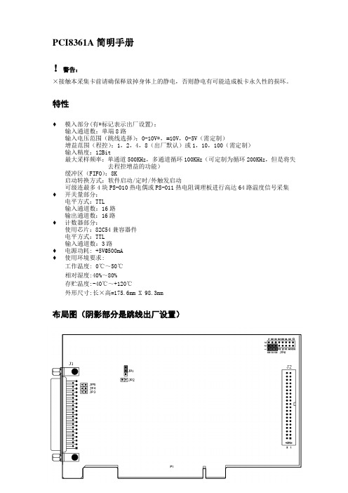
PCI8361A简明手册!警告:×接触本采集卡前请确保释放掉身体上的静电,否则静电有可能造成板卡永久性的损坏。
特性♦模入部分(有*标记表示出厂设置):输入通道数:单端8路输入电压范围(跳线选择):0-10V*,±10V,0-5V(需定制)增益范围(程控):1,2,4,8(出厂默认)或1,10,100(需定制)输入精度:12Bit最大采样频率:单通道500KHz,多通道循环100KHz(可定制为循环200KHz,但是将失去程控增益的功能)缓冲区(FIFO):8K启动转换方式:软件启动/定时/外触发启动可级连最多4块PS-010热电偶或PS-011热电阻调理板进行高达64路温度信号采集♦开关量部分:电平方式:TTL输入通道数:16路输出通道数:16路♦计数器部分:使用芯片:82C54兼容器件电平方式:TTL输入通道数:3路♦电源功耗: +5V@500mA♦使用环境要求:工作温度: 0℃~50℃相对湿度:40%~80%存贮温度:-40℃~+120℃外形尺寸:长×高=175.6mm X 98.3mm布局图(阴影部分是跳线出厂设置)出厂设置J1(模拟量输入和计数器输出接口)D型头注:ADx表示模拟量输入的第x通道AGND指模拟地,单端使用时为信号地使用时需将信号正接ADx,信号负接模拟地为防止引入现场干扰,不应该使AD输入信号引脚悬空,可以将不使用的信号引脚与模拟地短路TDIx TDOx是8361配合PS-010,PS-011时使用的控制脚,用户无需关心+5V,+12V,-12V通过JP3,JP4,JP5短接获得,主要用于给PS-010,PS-011供电用户无需关心J2(开关量输入输出和计数器输入接口)注:DIx表示开关量输入的第x通道DOx表示开关量输出的第x通道CLKx表示计数器输入的第x通道DGND指开关量信号地为了用户接线方便,我们随卡提供一根转接线,把卡上的J2(40PIN)转换为DB37(37芯D型头),引到计算机机箱外部。
MASTR II BASE STATION COMBINATIONS 产品说明书

LBI-31899FDESCRIPTION AND MAINTENANCE MASTR ® II BASE STATION COMBINATIONSTABLE OF CONTENTSPage SPECIFICATIONS . . . . . . . . . . . . . . . . . . . . . . . . . . . . . . . . . . . . . . . . . . . . 1FCC FILING NUMBERS . . . . . . . . . . . . . . . . . . . . . . . . . . . . . . . . . . . . . . . . 1COMBINATION NOMENCLATURE . . . . . . . . . . . . . . . . . . . . . . . . . . . . . . . . . 1DESCRIPTION . . . . . . . . . . . . . . . . . . . . . . . . . . . . . . . . . . . . . . . . . . . . . . 2SYSTEM DESCRIPTION . . . . . . . . . . . . . . . . . . . . . . . . . . . . . . . . . . . . . . . .2Receiver . . . . . . . . . . . . . . . . . . . . . . . . . . . . . . . . . . . . . . . . . . . . . . . . 2Transmitter . . . . . . . . . . . . . . . . . . . . . . . . . . . . . . . . . . . . . . . . . . . . . . 2System Board A1 . . . . . . . . . . . . . . . . . . . . . . . . . . . . . . . . . . . . . . . . . . . 2DC Remote Control . . . . . . . . . . . . . . . . . . . . . . . . . . . . . . . . . . . . . . . . . 3Tone Remote Control . . . . . . . . . . . . . . . . . . . . . . . . . . . . . . . . . . . . . . . . 3Channel Guard . . . . . . . . . . . . . . . . . . . . . . . . . . . . . . . . . . . . . . . . . . . . 3INITIAL ADJUSTMENT . . . . . . . . . . . . . . . . . . . . . . . . . . . . . . . . . . . . . . . . 3MAINTENANCE . . . . . . . . . . . . . . . . . . . . . . . . . . . . . . . . . . . . . . . . . . . . . 3OUTLINE DIAGRAMSSystem Board A901 . . . . . . . . . . . . . . . . . . . . . . . . . . . . . . . . . . . . . . . . . 5Harness 19C320811 . . . . . . . . . . . . . . . . . . . . . . . . . . . . . . . . . . . . . . . . . 5SCHEMATIC DIAGRAMSSystem Board A901 W/Cable Interconnect . . . . . . . . . . . . . . . . . . . . . . . . . . . . . 6STATION INTERCONNECT DIAGRAMSSystem Block Diagram . . . . . . . . . . . . . . . . . . . . . . . . . . . . . . . . . . . . . . . . 4Continuous Duty Station Harness Without Metering . . . . . . . . . . . . . . . . . . . . . . . 8Continuous Duty Station Harness With Metering . . . . . . . . . . . . . . . . . . . . . . . . . 10PARTS LISTContinuous Duty Station Harness Without Metering . . . . . . . . . . . . . . . . . . . . . . . 7Continuous Duty Station Harness With Metering . . . . . . . . . . . . . . . . . . . . . . . . . 7MASTR II Station Radio Panel . . . . . . . . . . . . . . . . . . . . . . . . . . . . . . . . . . . 7PRODUCTION CHANGES . . . . . . . . . . . . . . . . . . . . . . . . . . . . . . . . . . . . . . . 7MECHANICAL PARTS BREAKDOWNRadio Panel Front Door Assembly . . . . . . . . . . . . . . . . . . . . . . . . . . . . . . . . . 12Transmitter Power Amplifier . . . . . . . . . . . . . . . . . . . . . . . . . . . . . . . . . . . . 13Station Cabinets . . . . . . . . . . . . . . . . . . . . . . . . . . . . . . . . . . . . . . . . . . .14-15ILLUSTRATIONSFIGURE 1 - Radio Panel Front Door . . . . . . . . . . . . . . . . . . . . . . . . . . . . . . . . . . 2FIGURE 2 - Typical Station Assembly . . . . . . . . . . . . . . . . . . . . . . . . . . . . . . . . .2EEricsson Inc.Private Radio Systems Mountain View RoadLynchburg, Virginia 245021-800-528-7711 (Outside USA, 804-528-7711)Printed in U.S.A.Copyright © October 1987, General Electric CompanyNo one should be permitted to handle any portion of the equipment that is supplied with high voltage; or to connect any external apparatus to the units while the units are supplied with power. KEEP AWAY FROM LIVE CIRCUITS.High level RF energy in the transmitter Power Amplifier assembly can cause RF burns KEEP AWAY FROM THESE CIRCUITS WHEN THE TRANSMITTER IS KEYED.WARNINGSPECIFICATIONS*EIA DIMENSIONS (H X W X D)DESK MATE (30-INCH)30-1/4" X 21-1/2" X 15.5"DESK MATE (44-INCH)44-1/4" X 21-1/2" X 15.5"POLE MOUNT 45" X 21-l/2" X 21"FLOOR MOUNT 69" X 23" X 21"WEIGHTDESK MATE (30-INCH)160 lbs DESK MATE (44-INCH)180 lbs POLE MOUNT 225 lbs FLOOR MOUNT 290 lbsINPUT VOLTAGE121/242 VAC, 60 Hz Only (50 Hz Optional)AC INPUT POWERRF OUTPUT POWER TRANSMIT RECEIVE STANDBY LOW BAND100 WATTS 260 WATTS 105 WATTS 65 WATTS HIGH BAND40 WATTS 270 WATTS 75 WATTS 40 WATTS 110 WATTS 560 WATTS 105 WATTS 65 WATTS UHF40 WATTS 270 WATTS 75 WATTS 40 WATTS 100 WATTS560 WATTS105 WATTS65 WATTSTEMPERATURE RANGE-30° TO + 60°C (-22 to + 140 F)* These specifications are intended primarily for the use of the serviceman. Refer to the appropriate Specification Sheet for the complete specifications.FCC FILING NUMBERSMODEL SERIES FCC FILING NO.DUTY CYCLE POWER OUTPUT LOW BANDC74KT-61-A CONTINUOUS 50 - 100 WATTS HIGH BANDC56KT-47-J CONTINUOUS 10 - 40 WATTS C76KT-49-J CONTINUOUS 20 - 110 WATTS UHFC55KT-55-K CONTINUOUS1 - 40 WATTS C75KT-114-KCONTINUOUS30 - 100 WATTS(o) /CABINET/STYLE (1st Digit "D", "S", "P", or "V")NOTE: FCC Filing number not relevant to equipment operating in the 406 - 420 MHz frequency range.COMBINATION NOMENCLATURELBI-31899F1DESCRIPTIONThe MASTR II radio station combinations are designed for either DC or Tone Remote Control or Repeater operation. The station receiver is mounted on a shielded enclosure on the radio panel front door, along with a receiver system board which accommodates Channel Guard and other op-tion boards. Jacks are provided on the system board for plug-in interface with the options and control functions. The transmitter exciter is located in a separate shielded compartment on the radio panel front door. See Figure l. The continuous duty transmitter power amplifier hinges from the bottom of the radio housing. The PA assembly consists of a frame mounted to a heat sink. A cover snaps over the frame to form an RF-tight enclosure for the PA board assembly.Directly above the PA assembly is the station control shelf. This shelf houses the Control Panel and the Mini Backplane option S3MB01. The option cards used with the Control Shelf are installed in the Mini-backplane housing. These options include: Auxiliary Control, Auxiliary Receiver (DC or Tone), and Scan functions. Refer to LBI-31877 for a complete description of Mini Backplane option S3MB01. Two front panels are used: one for all station applications and one for repeater applications. A Front Panel is shown in Figure 2. Typical Front Panel controls include the trans-mit (TF1-TF4) and receive (RF1-RF4) frequency select, REM PTT, Speaker, Auxiliary receiver, ICOM (Intercom) and TEST switches, and the VOLUME Control. Indicators include the TX (transmit), RPTR Disable, and Frequency Select (F1-F4).External control connections are made to TB1201 located on the back of the Control Shelf.The station power supply is connected to a 121 VAC power source. Conversion from 121 VAC to 242 VAC is made by jumper changes on the back of the power supply front panel. The input voltage is stepped down to 12 Volts by a ferro-resonant transformer which provides line regulation of 2% for a 20% primary change. A power switch, primary and secondary fuses and two AC outlets are located on the front panel. A high-current fuse is located on the back panel.SYSTEM DESCRIPTIONRECEIVERThe station receiver consists of an oscillator/multiplier as-sembly (OSC/MULT), RF Assembly, Mixer/IF Assembly(MIF) and IF-Audio Squelch Assembly (IFAS). In receiverswith noise blankers, the noise blanker circuit replaces thestandard MIF board. Refer to the Receiver MaintenanceManual for a complete description of the station receiver.TRANSMITTERThe station transmitter consists of an exciter board assem-bly and a power amplifier assembly. In continuous dutytransmitters, the PA assembly consists of a printed wiringboard mounted on a heat sink at the rear of the radiohousing. In intermittent duty stations, the heat sink assem-bly is fastened to two sheet metal adaptor plates which hingeat the radio panel. Refer to the transmitter MaintenanceManual for a complete description of the station transmit-ters.SYSTEM BOARD A1The station System Board is located on the Radio PanelFront Door and the receiver modules plug directly into theboard. Along the edge of the System Board are two connec-tors which interconnect with the Remote Control Shelf andPower-Supply. Plug-in Channel Guard and Carrier Control~ Timer option jacks are provided. A metering jack isprovided for accommodating the General Electric Model4EX3A11 Test Set. VOLUME Control R3 is located on theSystem Board. SQUELCH Control R901 is located on theRadio Panel Front Door.A jumper is normally present between J933-4 and J933-8in single-frequency transmit stations. A jumper is also pre-sent between H47 and H48 on A901 in single-frequencyreceive stations. In multiple-frequency receive stations, se-lecting a particular receive frequency at the remote controlunit applies a ground to the particular pin at J931 corre-sponding to the frequency selected. The ground is thenconnected via the System Board printed wiring to the re-ceiver. OSC/MULT to select the desired oscillator.VOLUME/SQUELCH from the receiver Audio PreAmp isconnected via J904-12 to the VOLUME (R3) andSQUELCH (R901) controls. The VOLUME arm is returnedto the receiver IFAS Board where the signal is amplified bythe receiver audio power amplifier circuit. The audio outputof the PA is then connected to the speaker leads at J904-18& 19. The station VOLUME control (R3) is normally ad-justed for 1-watt output and the station speaker level iscontrolled by the service speaker VOLUME control.Figure 1 - Radio Panel Front DoorFigure 2 - Typical Station AssemblyLBI-31899F 2DC REMOTE CONTROLIn DC Remote Control Systems, DC currents are selectively applied to a telephone pair at a remote control console to set the system operating characteristics. Items that are controlled by the DC Remote Control system include selecting the num-ber of channels, scan option, Channel Guard Disable, Re-peater Disable, and Auxiliary Receiver. In some cases combinations of the above may be selected. Refer to the Control Panel Manual for details.TONE REMOTE CONTROLUp to 13 functions may be controlled in the Tone Remote Control system. This is accomplished by applying the speci-fied tone frequency at the prescribed level to the transmission medium at a remote control console for detection by the Tone Remote Control system on the Control Shelf. The controlled functions include transmitter/receiver selection, Rx Channel Guard Disable, Channel Guard or Repeater Enable/Disable, Auxiliary function on/off, repeater enable, scan or sim. moni-tor or repeater disable, and Tx hold. Refer to the Maintenance Manual for the Control Shelf for a complete description of the system.CHANNEL GUARDIn stations equipped with Channel Guard, the Channel Guard Board is plugged into the System Board at P908 and P909. Each MASTR II receiver is equipped with a tone reject filter to prevent the CG tone from being heard in the speaker. In addition, all transmitters are provided with a Channel Guard Modulation control which is adjusted for proper deviation. Channel Guard is a continuous tone controlled squelch system that provides communications control in accordance with EIA standard RS-220. The system utilizes standard tone frequen-cies from 721.9 to 203.5 Hz with both the encoder and oper-ating on the same frequency. The STE circuit (Squelch Tail Eliminator) employs a phase shift of approximately 180 de-grees in the encode function to eliminate an undesirable noise burst after each transmission.The decoder operates in conjunction with the receiver to inhibit all calls that are not tone coded with the proper Channel Guard tone frequency. The Volume/Squelch output of the receiver is applied to the Channel Guard decoder at P908-1. When the received signal is not properly coded with the CG tone, a ground is supplied through P908-5 to mute the re-ceiver. When a properly coded signal is received, the receiver unsquelches and the desired signal is heard. In duplex combi-nations, a separate encoder is used in the exciter and a separate decoder is used in the receiver.A Channel Guard Filter is used in the remote audio to attenu-ate frequencies below 203.5 Hertz to prevent the ChannelGuard tone from being applied to the remote audio pair.A repeater will not key in Channel Guard systems unless thereceived signal is coded with the proper Channel Guard tone.The CG MONITOR function when selected will not allow therepeater to key on an encoded signal but will allow theoperator to hear all channel activity.INITIAL ADJUSTMENTAfter the MASTR II station has been installed as described inthe Installation Manual, the following adjust-ments should bemade by an authorized electronics technician before the sta-tion is placed in service.TEST EQUIPMENT REQUIRED1.Deviation Monitor2.Wattmeter, 50 ohms, rated power3.RF Generator, (Station RF Frequencies)4.AC Voltmeter5.30 dB CouplerTRANSMITTER ADJUSTMENTTransmitter adjustment includes measuring the forward andreflected power and adjusting the antenna length for optimumratio, then setting the transmitter to the rated power output.Next measure and record the frequency and modulation forfuture reference. For complete transmitter adjustment proce-dures, refer to the Alignment Procedure in the applicable radioMaintenance Manual.RECEIVER ADJUSTMENTInitial adjustment of the receiver includes tuning the inputcircuit to match the antenna, adjusting the station volumecontrol, and setting the station squelch control. Refer to theFront End Alignment and Adjustment Procedures in the Main-tenance Manual.STATION VOLUME (R3 on System Board)1.Apply a 1000 microvolt on-frequency test signal modulatedby 1000 Hz with 3 kHz deviation to the receiver antennajack J937.2.Turn service speaker switch (S1) to desired RCVR posi-tion.3.Connect an AC Voltmeter across J905 terminals 1 & 2and adjust R3 for a reading of 6.3 Volts RMS on the meter.4.Set VOLUME switch S2 on the service speaker to thedesired listening level.STATION SOUELCH (R901 on ReceiverExciter Door)1.Turn the SQUELCH control clockwise as far as possible.2.Turn the SQUELCH control counterclockwise until thenoise just disappears, then advance the control (clock-wise) another 20 degrees.LOCAL CONTROL MODULATIONADJUSTMENT1.Apply a 1000 Hz, 1 VRMS signal across P3-2 (MIC HI)and P3-1 (low). Connect a 0.5 microfarad (or larger) DCblocking capacitor in series with the MIC HI lead, P3-2.2.Set MOD ADJUST control R127 on the exciter for 4.5kHz deviation as indicated on a frequency modulationmonitor.3.While talking in a normal voice, at the station microphoneadjust LOCAL TX MOD LEVEL R222 (Tone Panel) orR46 (DC Panel) on the Control Panel for a deviation of 3to 4 kHz as measured on the deviation monitor.REPEATER CONTROL ADJUSTMENT1.Apply a 1000 Hz, on frequency signal modulated with1000 Hz tone at 3 kHz deviation to the station receiver.2.Adjust TX MOD control R60 on the Control Panel for a3.0 kHz deviation as indicated on the deviation monitor.REMOTE CONTROL ADJUSTMENTSThe transmitter modulation gain, the remote audio input andline output must be adjusted before placing the station inoperation. Refer to the DC Remote Control or the ToneRemote Control Maintenance Manual for these adjust-ments.REPEATER CONTROL ADJUSTMENTThe repeater drop out delay timing may be adjusted beforeplacing the station in operation. Refer to the MASTR IIRepeater Station Control Panel Maintenance Manual forthese adjustments.MAINTENANCETo insure high operating efficiency and to prevent mechani-cal and electrical failures from interrupting system opera-tion, routine checks should be made of all mechanical andelectrical parts at regular intervals. This preventive mainte-nance should include the checks listed in the table of Main-tenance Checks.TEST AND TROUBLESHOOTINGPROCEDURESThe individual Maintenance Manuals for the transmitterand receiver describe standard test procedures which thetechnician can use to compare the actual performance of thetransmitter or receiver against the specifications of the unitwhen shipped from the factory. In addition, specific trou-bleshooting procedures are available to assist the technicianwhen servicing the transmitter and receiver.Removing IC "s and other soldered-in components can beeasily accomplished by using a de-soldering tool. To re-move an IC, heat each lead separately on the solder side andremove the old solder with the de-soldering tool.An alternate method is to use a special soldering tip thatheats all of the pins simultaneously.Adjusting the VOLUME control for levels higher thanspecified may cause damage to the speaker.CAUTIONLBI-31899F3SYSTEM INTERCONNECTION DIAGRAMMAINTENANCE CHECKS INTERVAL BETWEENCHECKSEvery 6monthsAs RequiredTransmitter Alignment: Compare meter readings at transmittermultiplier metering jacks with voltages read during initial tune up.Touch up multiplier tuning. Check power output. (See AlignmentProcedure for Transmitter).XReceiver: While receiving an unmodulated signal on the stationfrequency(s), adjust OSC-1 trimmer for each operating frequencyfor a zero discriminator reading. (See the Receiver AlignmentProcedure).XTransmission Line: Check for positive indication of pressure ontransmission line pressure gauge (if pressurized line is used).XAntenna: Check antenna & mast for mechanical stability.XMechanical Inspection: Visually check cables, plugs, sockets, ter-minal boards & components for good electrical connections. Checkfor tightness of nuts, bolts, & screws to make sure that nothing isworking loose from its mounting.XCleaning: Use a vacuum cleaner to remove dust which may haveaccumulated inside the cabinet.XFrequency Check: Check transmitter frequency & deviation.X LBI-31899F4WIRING HARNESS 19C320811SYSTEM BOARD A901OUTLINE DIAGRAM(19D423147, Rev. 3)(19D417205, Sh. 2. Rev. 4)COMPONENT SIDE(19D423147, Rev. 2)(19D417205, Sh. 2. Rev. 4)SOLDER SIDE(19C328112, Rev. 2)LBI-31899F5SCHEMATIC DIAGRAM LBI-31899FSYSTEM BOARD A90119D417262G1(19E501154, Rev. 25)6MASTR II STATION RADIO PANELFRONT DOOR ASSEMBLY19D417262G1DESCRIPTION AND MAINTENANCEPARTS LIST & PRODUCTION CHANGESSYMBOL PART NUMBERDESCRIPTION A901COMPONENT BOARD19D417213G1— — — — CAPACITORS — — — — —C119A116080P107Polyester: 0.1 uF ±10%, 50 VdcW.C219A115680P24Electrolytic: 400 uF +150% -10%, 18 VdcW; sim to Mallory Type TTX.C319A116080P106Polyester: 0.068 uF ±10%, 50 VdcW.C419A701534P4Tantalum: 1 uF ±20%, 35 VdcW.thru C7C819A701534P8Tantalum: 22 uF ±20%, 16 VdcW.— — — — —JACKS — — — — — —J903Connector. Includes:and J90419A116659P1Connector, printed wiring: 3 contacts rated at 5 amps; sim to Molex 09-52-3032.19A116659P4Connector, printed wiring: 6 contacts rated at 5 amps; sim to Molex 09-52-3062.J90519B219374G2Connector, 9 contacts. Includes: Shell.J9364033513P4Contact, electrical: sim to Bead Chain L93-3.J937Part of W901 & W905.J938Part of W902 & W906.J95119A116659P13Connector, printed wiring: 4 contacts rated at 5 amps; sim to Molex 09-64-1041.J952Connector includes:19A116659P11Connector, printed wiring: 7 contacts rated at 5 amps; sim to Molex 09-64-1071.19A116659P12Connector, printed wiring: 6 contacts rated @ 5amps; sim to Molex 09-64-1061.— — — — — PLUGS — — — — — —P907Part of A901thru P909P934Part of A901and P935— — — —RESISTORS — — — — —R119A701250P444Metal film: 280K ohms ±1%, 1/4 w.and R2R319B209358P106Variable: 10K ohms ±5%, 1/4 w; sim to CTS X-201.R419A700106P71Composition: 2.2K ohms ±5%, 1/4 w.R519A700106P75Composition: 3.3K ohms ±5%, 1/4 w.R619A700113P3Composition: 3.3 ohms ±5%, 1/2 w.— — — MISCELLANEOUS — — — —5491541P302Spacer. (Used in G1).19B219761P3Jumper (Used in G1).— — — — — CABLES — — — — — —W90119B233742G1Cable, RF: approx 14 inches long, 350 VRMS, 500 Vdc operating voltage.W9025491689P104Cable, RF: approx 4 inches long, 350 VRMS, 500 Vdc operating voltage.W903CABLE ASSEMBLY 19D417262G2— — — — —JACKS — — — — — —J93119C851861P1Assembly.and J932*COMPONENTS, ADDED, DELETED OR CHANGED BY PRODUCTION CHANGESSYMBOL PART NUMBERDESCRIPTION19C317957P2Connector, Includes: Shell.19A700237P1Contact, electrical: sim to Malco 003-0132-001.19A116781P3Contact: 16-20 AWG; sim to Molex 08-50-0105.— — — — — — PLUGS — — — — — — — P101Part of W902 & W906 (Used in G1).P301Part of W901&W905 (Used in G1).P907Part of AX01 (Used in G1).P908Part of A901 (Used in G1).and P909P934Part of A901 (Used in G1).and P935P95119A116659P25Shell.and P952— — — — — RESISTORS — — — — — —R9015496870P31Variable, carbon film: 10K ohms ±20%, sim to Mallory LC(25K). (Used in G2).W904EXCITER CABLE 19D417262G3J93319C851861P1Assembly.— — — — — — PLUGS — — — — — — —P90119A116659P25Shell.P90619A127042P1Terminal, solderless: sim to Malco 12093-12.— — — — MISCELLANEOUS — — — — —7878455P1Lug terminal; sim to GE89473. (Used in G1).19A116781P4Contact: 22-26 AWG; sim to Molex 08-50-0107.(Used in G2 and G3).19A701785P1Contact, electrical; sim to Molex 08-50-0404.(Used with P907, P908, P909).19C320679G1Door. (Used in G1).19C320664P1FR (Used in G1).19B226035G1Support (Used in G1).19B226105G2Support (Used in G1).19B234589P1Pawl. (Used in G1).19C336435P1Knob. (Used in G1).N193P808B6Tap Screw;, Phillips POZIDRIV: No. 6-20X 1/2 (Part of door latch)5493361P8Washer, spring tension.(Part of door latch)4035664P8Nut, self locking. (Used on hinge).19A115161P2Sleeving. (Used in G1).19B226035G2Support (Used in G1).N402P39B6Flatwasher: No. 10. (Used in G1).19A115874P1Catch, friction. (Used in G1).19B201074P204Tap screw, phillips POZIDRIV: No. 4-40 x 1/4.(Used with P101).19A116686P2Nut, sheet spring. (Used in G1).N529P11B6Plug Button (Used in 3/8 inch hole).19B201074P305Tap screw, Phillips POZIDRIV: No. 6-32 x 5/16.(Used to secure J937).19B209519P1Polarity tab. (Used with P901, P951, and P952.19A121676P2Guide Pin (Used with J931-J933).19A116496P1Cable clip. (Used in G1).7115130P9Lockwasher, Internal tooth: No. 3/8. (Used in G1).7165075P2Hex nut, brass: thread size No. 3/8-32. (Used in G1).4037158P4Rubber channel. (Used in G1).N529P18B6Plug button (Used in G1).LBI-31899F7INTERCONNECTION DIAGRAM LBI-31899FCONTINUOUS DUTY STATION HARNESSWITHOUT METERING 19C320811G1(19R622032, Rev. 15)8INTERCONNECTION DIAGRAM CONTINUOUS DUTY STATION HARNESSWITHOUT METERING 19C320811G1(19R622032, Rev. 15)LBI-31899F9INTERCONNECTION DIAGRAM LBI-31899FCONTINUOUS DUTY STATION HARNESS (CONT.)WITH METERING 19C320811G4(19R622055, Rev. 14)LBI-31899F INTERCONNECTION DIAGRAMCONTINUOUS DUTY STATION HARNESSWITH METERING 19C320811G4(19R622055, Rev. 14)RADIO PANEL FRONT DOORMECHANICAL PARTS BREAKDOWN LBI-31899FLBI-31899F MECHANICAL PARTS BREAKDOWNTRANSMITTER POWER AMPLIFIERMECHANICAL PARTS BREAKDOWN LBI-31899FSTATION CABINETSLBI-31899FSTATION CABINETS。