Sensor图案自动生成软件指导书
EOS操作手册

398
5
omega Kappa
-2.7669 96 4.6971 23
11.0010 47 173.331 625
StripID 1
2
2 EOS 安装与配置
2.1 安装 setup
选择安装包下的 setup 文件,根据提示操作即可成功安装。
2.2 系统配置
项目 CPU 内存 硬盘 显卡 操作系统
建议参数 4 核以上,主频 3.0GHZ 16GB 以上 7200 转/秒及以上 1GB 以上 64 位操作系统
1.2 软件概述
EOS 航空影像 DSM/DOM 自动生成及编辑软件是以空三成果为输入,以计算机视觉 以及形态学等相关理论为理论基础设计的针对航空数字影像的成果生产软件;
EOS 系统包含 DSM/DEM 自动匹配模块,数字正射影像纠正模块、快速 DOM 镶嵌 模块以及快速成果输出模块、以及 DOM 编辑模块、DEM 编辑模块。系统基于高度智能 化的目标,流程的设计考虑尽量减少人工干预过程,并为用户提供了方便的交互界面和 接口;系统实现基于灵活组装架构模式,用户可根据实际的生产需求定制生产流程。
1.3 输入数据约定
使用 EOS 系统,创建新的工程,需要几种不同的数据输入,对于各种输入数据的 约定如下: 影像数据
支持 TIFF 和 JPG 格式 相机文件:
camera_name=Canon_450D type = pixel x0 = 1913.666667 y0 = 1293.403509 f = 4283.175439 k1 = 5.922927e-009 k2 = -2.836397e-016 k3 = 0.000000 p1 = 1.622790e-007 p2 = 1.578330e-008 pixel_width = 3888 pixel_height = 2592 mm_width = 22.161600 mm_height = 14.774400
综合烧录指导书

如果有为独立节点设置测试参数,则设置的节点会变成蓝色,用鼠标框选这些 节点后,双击鼠标,可以清除设置:
当测试发现问题时,如下图所示,在日志区会提示测试失败,然后显示出具体 失败的条目,如“最大值超过限定”、“最小值超过限定”、“相邻数据偏差 超限”、“整屏数据最大偏差超限”。
当测试失败时,点击【原始值】按钮可以看到测试不通过的详细原因,红色 数据为不通过数据,将鼠标放在红色数据上面,会提示失败原因:
2) 测试环境或者测试治具的原因。 a) 电源波动比较大时,有可能造成测试结果的不稳定。 b) 模组AVDD 或者Sensor EVDD 电压设置错误。电压会影响原始值的大小。 c) 测试治具的干扰。比如Sensor 测试时,Sensor 测试板与Sensor 的连接线过长或者 互相缠绕,可能造成数据不稳定。 d) GT9 系列IC 频繁测试出几百K 以上的短路阻抗时,可能是测试环境干扰导致误测, 请改善测试环境,并保证测试治具有效接地。
2)原始值最小值超限\按键最小值超限:只要差值满足要求,原始值最小值可以调 整到略小于当前Sensor 上的最小值附近,但不能小于屏上数据太多,必须逐步验证、 逐步调整。 3)相邻偏差、整屏偏差超限:相邻偏差是影响画线线性度的主要因素,对于 GT818\GT801 等小屏,相邻偏差一般设定在0.2-0.25 以内,对于多芯片方案,由于 TP 大,屏上数据不均匀现象比较严重,芯片对此有做特殊处理,可以将相邻偏差 放宽到0.4-0.5。相邻偏差过大时,建议多做验证,确认效果。测试时,相邻偏差 测试通过,将不再测试整屏偏差,只有相邻偏差与整屏偏差全部 NG 时,测试结果 才NG。
数据(TP)分析
X 轴为感应线(Rx)方向,Y 轴为驱动(Tx),如果有配置按键,则最下一行(Key)为 按键数据。
PCO.1200shs操作手册V3.13-1408
第三章 相机控制及参数设置 ........................................................................................... 24
3.1 Timing .............................................................................................................................................24 3.2 Sensor(size).....................................................................................................................................25 3.3 Sensor(misc.) ..................................................................................................................................27 3.4 CamRam .........................................................................................................................................27 3.5 Recording ........................................................................................................................................28
Ishow软件使用说明(说细)
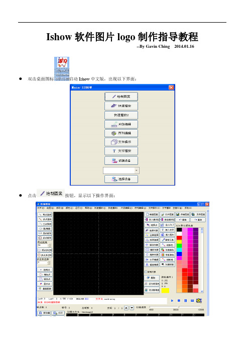
Ishow软件图片logo制作指导教程--By Gavin Ching 2014.01.16 ●双击桌面图标启动Ishow中文版,出现以下界面:●点击按钮,显示以下操作界面:图形导入:点击按钮,PLT是矢量图,需先用coreldraw软件制作PLT文件,如下图示:如上图:单击按钮,找到准备好的plt后缀文件,点击按钮,出现以下图示单击,建议将图形粗糙度设为0(拖动滑块至最左),可以通过“图形尺寸系数”调整图片大小,如下图示:●点击后,出现如下界面:●点击软件右侧的,然后将鼠标指针放到图案上,并单击左键一次,此时移动鼠标图案会跟随移动,一般将要编辑的图案放在中间区,确定放置位置后,再次单击鼠标左键一次,如下图:●单击,以便查看图片整体情况,如下图示:●由上图看Big Dipper这部分区域需要细节处理,使线条更完善。
为了更易于编辑图案,我们将图片暂时局部放大:单击,然后将鼠标在Big Dipper的左上角空白昝“单击一下”后松开,随后将鼠标移动到Big Dipper右下角,使整个矩形框覆盖Big Dipper,然后单击左键,完成选择。
如图:接下来,单击,在已选中的“Big Dipper”周围左单击一下鼠标并松开,然后慢慢移动鼠标就可以看到所选图案会随之放大或缩小,选择合适的大小后,再左单击一下鼠标左键,完成此项操作。
如图得到:●此时我们发现红色太晃眼,而且那个红方框有点碍事,现在先将整个图案换成绿色,并删掉方框:单击,并在右侧选择“绿色”,然后再点击和如下图:●单击,在右上角处,左单击鼠标一次后松开并移动鼠标,会有一个红色矩形选框出现,再次单击鼠标左键,完成绿色矩形框的选中。
点击按钮,完成删除操作。
如下图:●下面进入细节修改,单击,选择里面“黑色”。
然后点击,在需要删除的“线条”上单击。
得到如下图所示图:●仔细看上图会发现有点该是圆形的图案,成了菱形,也需要修补。
仅以Big的“g”为例子。
点击软件左下处的,在上点击四下,先增加四个点,如图:。
视觉科技视觉技术解决方案生成器用户指南说明书
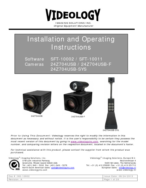
Prior to Using This Document: Videology reserves the right to modify the information in this document as necessary and without notice. It is the user’s responsibility to be certain they possess the most recent version of this document by going to , searching for the model number, and comparing revision letters on the respective document, located in the document’s footer. For technical assistance with this product, please contact the supplier from whom the product was purchased.Videology® Imaging Solutions, Inc. Videology® Imaging Solutions, Europe B.V.37M Lark Industrial ParkwayGreenville, Rhode Island 02828 USATel: (401) 949 – 5332 Fax: (401) 949 – 5276North/South American Sales: **********************Neutronenlaan 45405 NH Uden, The NetherlandsTel: +31 (0) 413 256261 Fax: +31 (0) 413 251712European Sales: *****************www.videology.nlOriginal Equipment Manufacturer24Z704USB24Z704USB-SYS24Z704USB-FLicense Agreement (Software):This Agreement states the terms and conditions upon which Videology Imaging Solutions, Inc. USA and Videology Imaging S olutions, B.V. Europe (hereafter referred to as "Videology®") offer to license to you the software together with all related documentation and accompanying items including, but not limited to, the executable programs, drivers, libraries, and data files associated with such software.The Software is licensed, not sold, to you for use only under the terms of this Agreement.Videology grants to you, the purchaser, the right to use all or a portion of this Software provided that the Software is used only in conjunction with Videology's family of products.In using the Software you agree not to:•Decompile, disassemble, reverse engineer, or otherwise attempt to derive the source code for any Product (except to the extent applicable laws specifically prohibit such restriction);•Remove or obscure any trademark or copyright notices.Limited Warranty (Hardware and Software):ANY USE OF THE SOFTWARE OR HARDWARE IS AT YOUR OWN RISK. THE SOFTWARE IS PROVIDED FOR USE ONLY WITH VIDEOLOGY'S HARDWARE. THE SOFTWARE IS PROVIDED FOR USE "AS IS" WITHOUT WARRANTY OF ANY KIND, TO THE MAXIMUM EXTENT PERMITTED BY LAW, VIDEOLOGY DISCLAIMS ALL WARRANTIES OF ANY KIND, EITHER EXPRESS OR IMPLIED, INCLUDING, WITHOUT LIMITATION, IMPLIED WARRANTIES OR CONDITIONS OF MERCHANTABILITY, QUALITY AND FITNESS FOR A PARTICULAR APPLICATION OR PURPOSE. VIDEOLOGY IS NOT OBLIGATED TO PROVIDE ANY UPDATES OR UPGRADES TO THE SOFTWARE OR ANY RELATED HARDWARE.Limited Liability (Hardware and Software):In no event shall Videology or its Licensor's be liable for any damages whatsoever (including, without limitation, incidental, direct, indirect, special or consequential damages, damages for loss of business profits, business interruption, loss of business information, or other pecuniary loss) arising out of the use or inability to use this Software or related Hardware, including, but not limited to, any of Videology's family of products.Table of Contents1.Document History (4)2.General Descriptions (4)3.Specifications (5)4.Dimensions (6)4.1.24Z704USB (6)4.2.24Z704USB-F (6)4.3.24Z704USB-SYS (7)5.Minimum Computer System Requirements (8)6.Setup and Operation (9)6.1.Flash Camera Setup (24Z704USB-F) (9)6.1.1.Attaching the Illuminator on top of Flash Camera (9)6.1.2.Wiring and Power (9)6.1.3.Subject Distance (10)6.1.4.Flash Intensity (10)6.1.5.White Balance (11)B System Setup (24Z704USB-SYS) (12)6.2.1.Camera Placement (12)6.2.2.Control Panel (12)6.2.3.Power Connection (12)puter Connection (12)6.2.5.Illumination Control (12)6.2.6.Securing the System to the table top (12)7.Software (13)7.1.SFT-10002 USB Viewer Installation (13)ing the Videology Viewer (15)7.3.Basic Camera Controls (16)7.3.1.Zoom Control (17)7.3.2.Brightness (17)7.3.3.Exposure Control (17)7.3.4.Image Orientation Control (17)7.3.5.Image Capture Control (Snapshot) (17)7.4.Advanced Camera Functions (18)7.4.1.Manual White Balance (18)7.4.2.Focus (19)7.4.3.Shutter Speed (19)er Presets (19)7.5.TWAIN Data Source Installation (21)7.6.TWAIN USER Interface (22)8.Contact Information (23)1. Document History2. General DescriptionsThe camera and system are supplied with a software application for camera viewing and control. An SDKis also available for users who wish to integrate the viewing and control features into their own applications.The 24Z704USB camera is a standalone camera; it is not adaptable to the 24Z704USB-SYS system.• 2 megapixel progressive scan sensor• WDM, TWAIN, DirectX/DirectShow compatible • Still image capture with streaming video • Autofocus, 10x optical zoom• FIPS 201 compliance (in conjunction with appropriate software)The 24Z704USB-F camera has a Led Illuminator designed for use with the Videology 24Z704USB Autofocus Zoom Camera. It uses a powerful white LED to provide very bright scene illumination at distances up to 20 feet.• The intensity of the illumination can be varied using a small control wheelon the side of the illuminator.• The flash is controlled directly from the PC, and is triggered whenever asnapshot command is issued. This can be done from within the Videology Viewer Application, or by implementing the Flash Trigger provided as part of the camera SDK.• An In-Line Hub and Control unit is provided so that the flash unit may beeasily retrofitted to existing Zoom Cameras.The 24Z704USB-SYS is an ID badging system utilizing a 2 Megapixel Autofocus USB Zoom camera module and high brightness LED illuminator. It is designed for table top use, and provides high quality streaming video and single frame snapshot capabilities.• 2 megapixel progressive scan sensor• WDM, TWAIN, DirectX/DirectShow compatible • Still image capture with streaming video • Autofocus, 10x optical zoom• Cool energy efficient white LEDs replace “hot” incandescent light or flashand last 1000x longer• On/Off & dimming for LEDs• No shadows or hotspots due to lighting placement • Heavy steel construction • Flexible gooseneck stand• Small footprint saves table space• FIPS 201 compliance (in conjunction with appropriate software)RevisionIssue DateReason CN# Rev A 06-20-13 Initial release, replacing “24Z704USB family” manual 13-10333. SpecificationsEnvironmental Operating Temp. -10°C ~ 50°C (recommended 5° C ~ 40° C)Government ComplianceFIPS 201In conjunction with appropriate softwareElectrical24Z704USB 24Z704USB-F 24Z704USB-SYSImage Sensor 1/3” CMOS progressive scanActive Pixels (HxV) 1280 x 1024 Total Pixels (HxV) 1600 x 1200 Pixel Size3.0µm x 3.0µm Scanning SystemProgressive Scan Scanning Frequency (HxV) 19.5KHz x 15HzResolution 800 TVL Sensitivity1 lux (30 IRE) Display Resolution 1280 x 1024 Still Capture1280 x 1024 pixels Signal To Noise Ratio ≤ 40dB (max)Synchronization InternalScan Mode Progressive scanFlickerless Mode Yes (always on, NTSC/PALconfigurable)Contour Enhancement Yes (text mode or image mode)Mirror ModeYes(horizontal, horizontal + vertical)Positive/Negative Mode Yes Video OutputUSB 2.0 Control Communication USB busShutter Speed 1/20 - 1/1000 sec. White Balance Auto/manual Brightness Manual IrisAuto/manualPower Supply12VDC (10 - 14VDC) Power Consumption Camera is 1 Amp Max System is 3 AmpsSpecial Functions Freeze,H/V reverse, save & recall imagesLighting(24Z704USB-SYS only)6 lensed super bright LEDsUSB VideoVideo CaptureYes (via software) High Resolution Still Image CaptureYes (via software) Supported Image Formats Uncompressed YUV422USB BandwidthUSB 2.04.Dimensions 4.1.24Z704USBThe overall dimensions of the camera are shown in Figure 1.Figure 1.Overall Camera Dimensions4.2.24Z704USB-FThe overall dimensions of the flash camera are shown in Figure 2.Figure 2.Overall USB Flash Camera Dimensions USB connectorPowerFlashUSB connectorPower4.3.24Z704USB-SYSThe heavy-duty steel construction of both the stand and camera housing make for a robust and durable design. A flexible gooseneck mount permits the camera to be tilted from back to front or side to side. The overall dimensions of the USB system are shown in Figure 3.Figure 3.Overall USB System Dimensions5.Minimum Computer System RequirementsA PC with USB 2.0 compatible port.USB 1.1 not supported.MAC is not supported.Preview only•PIII- 1.1GHz or above•128MB of RAM (256MB preferred)•Windows XP/2000 for USB2.0•DirectX/DirectShow 9.0c or later•Windows XP Service Pack 1 (Service Pack 2 Preferred) Windows 2000 Service Pack 4 Preview and capture at the same time•Full D1 MPEG 2 - P4 – 2.4GHz or above•640 x 480 MPEG 2 - P4 – 2.0GHz or above•352 x 288 MPEG1 - P4 – 1.5GHz or above•Hard Disk - 5400RPM or above (7200RPM preferred)•128MB of RAM (256MB preferred)•Windows XP/2000 for USB2.0•DirectX/DirectShow 9.0c or later•Windows XP Service Pack 1 (Service Pack 2 Preferred) Windows 2000 Service Pack 4 Verify system has the latest USB 2.0 host driver from Microsoft® only.Verify that USB host controller chipset is Microsoft certified.This product is not guaranteed to operate with a USB 2.0 host driver from OWC.6.Setup and Operation6.1.Flash Camera Setup (24Z704USB-F)6.1.1.Attaching the Illuminator on top of Flash CameraThe illuminator is shipped with a mounting foot which is attached to the top of the camera using 2 screws, as shown in the illustration below.Attaching the LED illuminator to the 24Z704 CameraFlash Unit Mounted on Camera. Note the intensity control on the side of the flash unit.Conversely, the LED flash unit may be attached to the camera using the Small Velcro™ pads provided.With the foot attached to the camera, the illuminator simply snaps into place.6.1.2.Wiring and PowerThe Led Illuminator is provided with an In-Line Control unit that provides both power and control to the flash and also replaces the existing USB connection to the Zoom camera module, as shown in Figure 3.Connect the in-line Hub to the camera, flash and PC as shown, and connect the 12DC power to the rear of the camera.In Line Hub and Control Unit Connections6.1.3.Subject DistanceFor best results, the subject should be placed at a distance of not less than 6 feet from the camera. This will provide uniform, glare free illumination from the flash.6.1.4.Flash IntensityThe brightness of the LED flash can be adjusted using the small thumb wheel on the side of the flash unit.Turning the wheel from front to back will reduce the light intensity.The intensity setting will vary depending upon the ambient light level and distance from the camera to the subject so some experimentation may be required to get the correct setting.6.1.5.White BalanceThe 24Z704USB zoom camera has an automatic white balance (AWB) feature which enables the camera to adjust to varying illumination conditions such as sunlight, fluorescent lighting, incandescent lighting etc.This AWB feature works well under most circumstances, but if the scene contains a disproportionate amount of a single color, the color reproduction may be affected.This may happen if a colored backdrop is used for portrait pictures for example.A blue back drop, for example, may cause skin tones to become yellowish.To overcome this problem, manual white balance adjustment should be used. For more information on this function, refer to the user manual for the 24Z704USB Zoom Camera.Similarly, if the room lighting is very different in intensity and color temperature from the flash, it may be necessary to use manual white balance to obtain the best image quality.6.2. USB System Setup (24Z704USB-SYS)6.2.1. Camera PlacementThe system is designed for tabletop use, and should be located within 6ft of the PC to which it will be connected. If necessary, the system may be secured to the table top using the clamps provided (see figure 4)6.2.2. Control PanelControl Panel6.2.3. Power ConnectionThe power supply is a universal type, and will operate on any 120/240V 50/60Hz AC supply. Simply plug the AC power cord into a power outlet and connect the output cable from the power supply to the DC input jack on the control panel of the system (see Figure 3)6.2.4. Computer Connection Connect the system to the computer using the standard USB cable supplied.6.2.5. Illumination ControlThe LED illuminators are housed in the camera stand, and the illumination intensity can be varied using the rotary control located on the base of the unit. See Figure 3. We recommend that you do not leave the LEDs on full brightness for an extended length of time, as this may reduce their lifetime.6.2.6. Securing the System to the table topThe badging system is supplied with small clamps that can be used to secure the system to the tabletop. The clamps are installed into the four rectangular slots in the base and secured to the table with #6 screws as shown in figure 4.Securing the System to the tabletopPower Brightness Control LED USB Connector Power Input7.Software7.1.SFT-10002 USB Viewer InstallationTo install the viewer application on your Windows OS system; Run the SetupPZV.exe program from the CD provided with the system/camera.A window pop-up will show asking if you want to install the Videology Power Zoom Viewer and the Flash Unit Driver.For 24Z704USB cameras and 24Z704USB-SYS USB systems☒ Videology Power Zoom ViewerFor 24Z704USB-F cameras, check both checkboxes.☒ Videology Power Zoom Viewer☒ 24Z Flash Unit DriverClick Install.The following dialog box will appear.If you wish to install the viewer in a location other than the default directories, click on the Browse button and specify the desired location, otherwise click on the Install Button, and the following screens will appearClick Close.Simply connect the camera to a USB (2.0) port on your computer and launch the viewerfrom the desktop icon.ing the Videology ViewerAfter software installation, plug in the USB cable from the camera. A window will pop up stating that Windows is installing the device drivers:Upon completion a second window will state the driver software installed successfully:7.3. Basic Camera ControlsAfter software installation, open the PowerZoom software NOTE: Allow a few seconds after connecting the camera to the USB port. The camera is ready for operation when #1 appears in the box next to the Start button. Click on the START button in the top left hand corner and the camera image will appear. The viewer includes basic controls for adjusting the Zoom Level, Brightness, Exposure Mode and White Balance Settings of the camera. Also included within the basic control panel are the Image capture controls:Basic Viewer Control PanelImage Orientation ControlWhite Balance and Exposure ControlImage Capture ControlCamera is ready when the #1 appears Zoom and Brightness Control7.3.1.Zoom ControlThe Zoom control simply adjusts the level of magnification and thus the angular field of view of the camera. To zoom in or out, simply press and hold the up or down arrow (see figure 5) until the required field of view is obtained.7.3.2.BrightnessThe brightness control adjusts the overall image brightness. To increase or decrease the brightness of the image, simply press and hold the up or down button (see figure 5) until the required image brightness is obtained.7.3.3.Exposure ControlIf the Auto Exposure control is checked, then the camera will automatically adjust to variations in light intensity by opening or closing the aperture of the lens.If the Auto Exposure button is unchecked, then the lens aperture will remain at its current setting. It is recommended that the Auto exposure mode be used for most applications, and this is the default setting.7.3.4.Image Orientation ControlThe image orientation control allows the user to flip the image either horizontally or vertically.7.3.5.Image Capture Control (Snapshot)Single frame images can be acquired and stored to a preset directory. Still image frames can be stored either as Bitmap (BMP), Graphics Interchange Format (GIF), Joint Photographic Experts Group (JPEG), or Portable Network Graphics (PNG) files.To set the location of the stored images select the “Change Snap Folder” option on the left hand side of the screen. Use the drop-down menu below this to select the required image format.To acquire an image, simply hit the Snapshot button on the left hand side of the viewer screen.7.4. Advanced Camera FunctionsTo access the Advanced Camera Functions, press “Ctrl D” on the keyboard. The following screen options will appear:Advanced Image Controls The advanced function menu allows you to adjust the following parameters: 7.4.1. Manual White BalanceThe manual white balance controls allow you to change the way in which colors are displayed. When using different types of lighting (fluorescent lights, incandescent lamps, sunlight etc.) color tones can vary, and to get the best color representation, it may be better to override the auto white balance feature of the camera and adjust the red and blue gain channels to achieve optimum color balance of the subject.Manual White Balance Controls Shutter Speed Focus Controls Save ButtonFor example, the color of objects viewed under incandescent lighting are shifted towards the red, whereas Fluorescent lighting can make objects appear bluer.There are two modes of operation of the White Balance control, automatic (AWB) and manual.In automatic mode the camera will adjust the colors automatically as the lighting conditions change.In manual white balance, the user can adjust the color settings to obtain the best color reproduction.NOTE: The manual color controls are only accessible via the Advanced Camera Functions.7.4.2.FocusThe 24Z704USB Badging camera is capable of focusing in both Automatic Mode and Manual Mode. It is important to note that the camera defaults to the setting previously set in either Videology Viewer Mode or Badging Software Mode.Because of this, it is important to always set the radio button for the Focus Control to your preference (Auto Mode/Manual Mode) when using the camera for the first time. (See Figure 6)7.4.2.1.When Autofocus FailsOccasionally the camera may have difficulty focusing especially in marginal lighting environments.Low contrast subjects, blue backgrounds or solid color walls, highly reflective subjects, or subjects in front of a very detailed background, may require adjustments to focus.In these situations it is best to set the camera from Auto Mode to Manual Mode and adjust the focus.Alternatively, the user can zoom out a bit in Auto Mode, which will cause the camera to refocus.7.4.3.Shutter SpeedThe shutter speed sets the integration time of the camera; this is analogous to the speed of a mechanical shutter on a conventional camera.To increase or decrease the shutter speed, simply press the up or down arrow.Each time you press the arrow, the shutter speed will be incremented by one step.A slow shutter speed should be used in low light conditions; a faster shutter speed should be used if the subject is moving quickly or under excessive light conditions.er PresetsWhen first setting up the 24Z704USB camera you may wish to establish Presets. The badging camera has 8 presets available that allow focus, white balance, etc. to be set for easy retrieval in subsequent camera usage.It is recommended that before saving a preset, the Manual radio button be set so that the camera “locks” in the desired Field of View immediately when a preset is retrieved.To save the current camera settings, simply click on the “Save Preset” button, and select one of the presets 1 through 8.NOTE the save function is only available through the advanced control panel (see figure 6), although the preset can be recalled (loaded) via the basic control panel.User Preset OptionsTo restore the camera to the factory default settings, select the Factory Reset option from the drop down list on the load presets menu.Load Preset Menu7.5. TWAIN Data Source InstallationTo install the TWAIN data source, insert the CD labeled Twain Data Source and double click the executable file named SFT-10011 - TDS.Note: the file name might be slightly different depending on the revision level of the software.The following window will appear.Do not install the TWAIN data source in any other folder other than the default folder. To do so will make the camera system inoperable.The TWAIN driver installation is now complete. Click Close to exit the hardware wizard.7.6.TWAIN USER InterfaceIf you have installed the Twain interface (SFT-10011 - TDS), you can use the camera with any TWAIN Compliant Application.The TWAIN interface will attach itself to the first Videology camera it finds connected to the computer. For the best operation, the Twain Interface is intended to run on a system with only one Videology camera installed.Any application that supports a TWAIN Data Source as a capture device can access the camera. The camera's image will appear as shown below.For descriptions of camera options, please refer to section 9 Basic Camera Controls.8. Contact InformationFor technical assistance with this product, please contact the supplier from whom the product was purchased. For OEM inquiries, contact Videology ® Imaging Solutions: Americas, Middle East, Far East & Australia: Europe & N. Eurasia: Videology ® Imaging Solutions Inc. 37M Lark Industrial Parkway Greenville, RI 02828 USA Tel: (401) 949-5332 Fax: (401) 949-5276 Videology ® Imaging Solutions Europe B.V. Neutronenlaan 4 5405 NH Uden The Netherlands Tel: +31 (0) 413-256261 Fax: +31 (0) 413-251712 Please visit our website: VIDEOLOGY IMAGING SOLUTIONS is an ISO 9001 registered video camera developer and manufacturer serving industrial, machine vision, biometric, security, and specialty OEM markets. Videology designs, develops, manufactures, and distributes video, image acquisition, and display technologies and products to OEMs worldwide.。
目录(自动生成)、正文、致谢、参考文献、附录
摘要无线传感器网络是一种全新的信息获取和处理技术,具有许多传统网络无法比拟的优点,可广泛应用于军事、医疗、灾难救助等环境中,已经成为现代通信技术中的一个热点研究领域。
由于无线传感器网络中的节点普遍能量受限,因而设计能量有效的无线传感器网络路由协议受到了学术界和工业界的高度重视。
本文在上述背景下概述了影响无线传感器网络路由协议设计的因素,指出了传感器网络路由协议的评价标准,介绍了几种主流的传感器网络路由协议,并选择典型的低能量自适应聚类层次结构(LEACH)协议进行了深入分析,着重描述了实现LEACH协议的关键算法,分析了该协议存在的优势与不足,并给出了一些修改的建议。
在上述工作的基础上,本文利用网络仿真软件NS-2对其进行建模,重点实现了LEACH协议、CSMA协议、网关处理的有限状态机模型(FSM),并结合节点模型和网络模型,在omnet的虚拟无线环境下建立了LEACH协议的仿真平台。
最后利用上述平台建立了两个包含不同数量节点的无线传感器网络,仿真了LEACH协议的实际运行情况,并根据相关定义统计了网络的生命周期,节点能耗等参数,最终得出了LEACH协议能够高效利用能量的结论。
本文建立LEACH协议仿真平台的相关工作,为针对该协议的后续改进研究作了铺垫,具有一定的应用价值。
关键词无线传感器网络;路由协议;LEACH;NS-2网络仿真AbstractMotivated by the advancement in sensor, embedded computing, networking and wireless communication technologies, wireless sensor network (WSN) is now regarded as a promising technology for pervasive information acquiring and processing. Since WSN could be deployed in diverse applications, such as military affairs, medical care, emergencies, and so on, it becomes a boosting research topic in modern wireless networking technology. Due to the limited power supply characteristics of individual sensor node, it is extensively desirable to find out ways to maximize the life time of WSN. Consequently, energy-efficient routing protocol has become a hotspot in both academic research and industrial practices.This thesis firstly summarizes the factors which dominate the energy-consumption characteristics of routing protocol for WSN. Some criteria are then presented to evaluate the performance of a given routing protocol. Secondly, after introducing several mainstream routing protocols, the Low Energy Adaptive Clustering Hierarchy (LEACH) will be addressed to elucidate its advantages and disadvantages. Some proposals are also discussed to improve the LEACH routing protocol.In addition, by employing the network simulation tool—NS-2, this thesis lays emphasis on modeling the Finite State Machine of LEACH protocol, CSMA protocol. After that, based on the node and network model, LEACH protocol’s simulation platform will be presented using omnet’s virtual wireless environment.Finally, by setting up two WSN application scenarios with different number of sensor nodes, the life-time of WSN and the node’s energy consumption of the WSN are collected and analyzed. It is validated that the LEACH protocol is energy-efficient, which is suitable for the requirement by practical WSN implementations. Moreover, the completed simulation platform offer a good beginning for the future studies on LEACH protocol and its improved variations.Key words Wireless Sensor Network; Routing Protocol; LEACH; Network Simulation Using NS-2目录1 引言 (4)2 绪论...............................................................................................................................2.1 无线传感器网络简介...........................................................................................2.2 无线传感器网络体系结构...................................................................................2.2.1 传感器节点组成........................................................................................2.2.2 网络体系结构............................................................................................2.2.3 协议体系结构............................................................................................2.3 无线传感器网络的特点.......................................................................................2.4 无线传感器网络的应用.......................................................................................2.5 NS-2介绍2.6 NS-2在不同环境下的安装3 总体设计 (12)3.1 激光的检测 (12)3.2 靶位的划分 (12)3.3 编码标准 (13)3.4 成绩的传送和处理 (13)3.5 其他说明 (13)4 硬件设计 (14)4.1 信号放大电路 (14)4.2 整形电路 (16)4.3 编码电路 (17)4.4 串行传送 (19)4.5 电平转换 (21)5 软件设计 (22)5.1 总体方案 (22)5.2 程序流图 (22)5.3 模块说明 (23)6 制作与调试 (26)6.1 硬件电路的布线与焊接 (26)6.2 调试 (26)7 结论 (28)致谢 (29)参考文献 (30)附录 (31)1 引言由于近年来传感器技术、嵌入式技术、分布式信息处理技术和无线通讯技术的发展,微型制造技术、通信技术及电池技术的改进,促使微小的传感器可具有感应、无线通信及处理信息的能力。
SXEarth_Pro帮助手册 (1)
SXEarth Pro V3.7 晟兴三维数字地球高级版用户手册北京晟兴科技有限公司2017年9月30日目录1 了解SXEarth Pro (1)1.1 SXEarth Pro介绍 (1)1.2 SXEarth Pro功能特点 (1)2 运行环境 (3)2.1 操作系统 (3)2.2 硬件环境 (3)2.3 OpenGL标准支持 (4)3 SXEarth Pro下载安装 (4)3.1 SXEarth Pro下载 (4)3.2 Windows版安装 (5)3.3 Linux版安装 (7)3.4 微信公众号 (8)3.5 界面样式 (8)4 SXEarth Pro基本操作 (9)4.1 项目文件 (9)4.2 天气环境 (9)4.3 窗口操作 (13)4.4 场景面板和属性面板 (14)4.5 二三维一体化 (14)4.6 二三维浏览 (14)4.7 触控浏览 (15)5 SXEarth Pro卫图下载 (16)5.1 卫图下载介绍 (16)5.2 谷歌地球影像和高程下载 (16)5.3 地图下载 (19)5.4 四种输出格式如何选择 (21)5.5 影像切片、高程切片 (21)5.6 卫图下载常见问题 (22)6 SXEarth Pro数据导入 (22)6.1 导入图像数据 (22)6.2 打开在线数据 (24)6.3 图像颜色调整 (26)6.4 导入高程数据 (29)6.5 编辑高程属性 (30)6.6 导入矢量数据 (32)6.7 编辑矢量属性 (33)6.8 添加遮罩层 (34)6.9 导入倾斜摄影模型 (35)6.10 导入三维模型 (36)6.11 编辑模型属性 (39)6.12 建筑建模工具 (41)6.13 添加Vaps-XT仪表 (42)6.14 添加KML文件 (42)6.15 添加粒子特效 (42)6.16 模型路径动画 (44)6.17 相机路径动画 (45)6.18 相机关键帧动画 (46)7 SXEarth Pro模拟飞行 (47)7.1 机场集成 (47)7.2 驾驶飞行 (47)7.3 更换机型 (47)7.4 读取飞行轨迹数据文件飞行 (47)8 SXEarth Pro与FlightGear集成 (48)8.1 FlightGear晟兴地球版介绍 (48)8.2 FlightGear晟兴地球版特点 (48)8.3 下载安装 (48)9 SXEarth Pro矢量编辑,态势标绘 (48)9.1 绘制和编辑矢量 (48)9.2 编辑矢量属性 (53)9.3 导出标记为模型 (53)9.4 态势标绘 (53)9.5 纹理填充矢量 (54)9.6 修改矢量样式 (56)9.7 矢量样式脚本 (58)9.8 导出矢量 (59)10 SXEarth Pro测量与分析 (60)10.1 测量工具 (60)10.2 通视分析 (61)10.3 地形截面 (62)10.4 视点位置 (63)10.5 经纬网格 (64)10.6 地形缩放 (65)10.7 高程晕渲 (66)10.8 油彩地形 (67)10.9 地形GLSL编辑 (68)10.10 配置在线GIS数据 (69)10.11 官方网站浏览 (73)11 SXEarth Pro工具 (75)11.1 位置查询工具 (75)11.2 模型格式转换工具 (76)11.3 图片格式转换工具 (77)11.4 图像切片工具 (78)11.5 矢量切片工具 (80)11.6 切片拼接工具 (81)11.7 TMS转Mbtile工具 (81)11.9 TFS转Mbtiles工具 (82)11.10 Mbtiles转TFS工具 (82)11.11 Mbtiles合并工具 (83)12 SXEarth Pro案例 (83)12.1 全球100个景点案例 (84)12.2 飞机沿曲线飞行案例 (84)12.3 矢量拉起案例 (84)12.4 高德地图案例 (84)12.5 几何体着色器案例 (84)12.6 全球建筑案例 (84)12.7 谷歌地球影像和高程案例 (84)12.8 Mbtiles格式读取案例 (85)12.9 矢量面区域填充植被模型案例 (85)12.10 多模型案例 (85)12.11 人口柱状图案例 (85)12.12 卫星按轨迹飞行案例 (85)12.13 多级shp读取案例 (85)12.14 体积云案例 (85)12.15 Splat油彩地形案例 (86)12.16 海洋Triton及舰船尾迹案例 (86)12.17 地面切开及模型填充案例 (86)13 SXEarth Pro更新记录 (86)13.1 3.8.0 更新记录 (86)13.2 3.7.0 更新记录 (86)13.3 3.6.0 更新记录 (87)13.4 3.5.0更新记录 (87)13.5 3.4.0更新记录 (88)13.6 3.3.1更新记录 (89)13.8 3.0.1更新记录 (89)13.9 2.9.1更新记录 (90)13.10 2.8.0更新记录 (91)13.11 2.7.0更新记录 (92)13.12 2.6.1更新记录 (94)13.13 2.3.0更新记录 (95)13.14 2.2.2更新记录 (96)13.15 2.2.0更新记录 (96)13.16 2.0.0更新记录 (96)13.17 1.8.0更新记录 (97)13.18 1.7.1更新记录 (97)13.19 1.6.1更新记录 (97)13.20 1.5.1更新记录 (98)13.21 1.3.1更新记录 (98)13.22 1.2.1更新记录 (98)13.23 1.1.1更新记录 (99)13.24 1.0.0发布 (99)1 了解SXEarth Pro1.1 SXEarth Pro介绍SXEarth Pro是一款永久免费的3DGIS平台软件。
CAPSense入门开发工具实验指导书-1.1

准备工作1.软件软件::PSoC Designer 5.0 PSoC Programmer 3.0以上开以上开发软件可登陆发软件可登陆 免费下载免费下载,,并依次全部安装并依次全部安装。
安装PSoC Designer 5.0时,如系统提示需要安装Microsoft Framework 2.0, 请登陆Microsoft 网站下载安装网站下载安装。
2.硬件硬件::PSoC FirstTouch 入门工具CY3270开发工具可登陆 的在线商店购买的在线商店购买,,或致电800-880-8051(中国地区中国地区))购买第一部分 基于PSoC Designer 5.0 (System Level)开发平台的设计1.1 温度感应设计通过外界温度高低控制LED 灯和蜂鸣器报警实验工具实验工具::PSoC 入门工具CY3270 软件环境软件环境::PSoC Designer 5.0 器件型号器件型号::CY8C21434 试验准备试验准备::按照FTK 使用指南安装好PSoC Designer 5.0软件软件,,PSoC Programmer 可以到--> Download Software 下载最新软件下载最新软件)) 具体内容具体内容::利用CY3270上的温度感应感测外界温度 使用LED 和蜂鸣器显示外界温度的变化当外界温度升高或降低时,LED 和蜂鸣器如下反应:温度LED 和蜂鸣器超过 41.4° C 红灯闪并且蜂鸣器报警30.5° - 41.4° C 红灯亮 25.2° - 30.5° C 绿灯亮 15.2° C – 25.2 C 蓝灯亮低于15.2° C 蓝灯闪并且蜂鸣器报警实验原理实验原理:::实验步骤:实验步骤1. 首先新建一个PSoC Designer项目,从主菜单点击文件,选“New Project”2. 选择System-level Project 输入文件名Temperature3. 进入Design界面,点击设计目录的Inputs按钮,找到CY3270 PSoC FirstT ouch Kit 文件夹Temperature,然后点击OK5. 添加输出,点击设计目录的Outputs按钮,CY3270 PSoC FirstTouch Kit 文件夹6. 添加一个LED – On/Off/ Blink驱动,把名字改为RLED,初始值设为off7. 添加一个LED – On/Off/ Blink驱动,把名字改为GLED,初始值设为off8. 添加一个LED – On/Off/ Blink驱动,把名字改为BLED, 初始值设为off9. 添加Buzzer-PWM驱动,出现一个“Add Output Driver”窗口,把名字改为Buzzer, 初始值设为off, 然后点击OK10. .添加评估器,点击Valuators,找到Transfer Function Valuators-> Set Point Region11. 双击,添加Set Point Region评估器,名字改为TempRange,然后点击OK12. 出现Select Input窗口选中Temperature,点击Next13. 点击Add SetPoint ,按照最初试验要求添加温度区间点Threshold 41.4/30.5/25.2/5.2,Hysteresis为0.5.14.选择好了输入,输出,评估器,接着定义输入输出关系,选中RLED,点击右键,选中Transfer Function15.然后选择PriorityEncoder16.再根据实验要求定义传输函数,超过41.4° C时,红灯闪;30.5° C – 41.4° C之间红灯亮;其他温度区间红灯灭If TempRange==TempRange__41_40_to_55_10_C,Then RLED= RLED__BLINKINGIf TempRange==TempRange__30_50_to_41_40_C,Then RLED= RLED__ONIf 1Then RLED= RLED__OFF全部关系定义好后点击OK17.同样的方式,25.2° C – 30.5° C之间时,绿灯亮;其他温度区间绿灯灭If TempRange==TempRange__25_20_to_30_50_C,Then GLED= GLED__ONIf 1Then GLED= GLED__OFF全部关系定义好后点击OK18. 同样的方式,0° C - 5° C时,蓝灯亮;小于0° C蓝灯闪;其他温度区间蓝灯灭If TempRange==TempRange__15_20_to_25_20_C,Then BLED= BLED__ONIf TempRange==TempRange__m10_10_to_15_20_C,Then BLED= BLED__BLINKINGIf 1Then BLED= BLED__OFF全部关系定义好后点击OK19.同样的方式定义,如果温度高于41.4° C或低于15.2° C时蜂鸣器发出警报, If TempRange==TempRange__41_40_to_55_10_C,Then Buzzer= Buzzer__LowIf TempRange==TempRange__m10_10_to_15_20_C,Then Buzzer= Buzzer__LowIf 1Then Buzzer = Buzzer__Off全部关系定义好后点击OK20.设计完成后,开始Build21.选择CY8C21434, 32-Pin QFN22.进入分配管脚界面,管脚分配取决于具体设计,现在按照FTK CY3270的设计分配管脚。
Master操作指导书1
MSTAR SENSOR测试软件安装使用指导
一、驱动安装
1.双击应用程序“CDM20802_Setup.ex e”,安装EVK板驱动软件。
2.安装完毕后会有如下对话框提示并自动关闭对话框。
3.驱动安装完后,即可在电脑上使用MSTAR测试软件。
二、烧录FW
1.连接EVK板到电脑上,拨码开关位1、2置为ON,打开应用程序“ISP_Tool.ex e”,在
<READ>选项中导入FW文件。
2.切换到CONFIG选项,设置如下图所示,其中I2C SPEED不能超过40。
3.点击CONNECT选项连接EVK板,连接成功如图所示:
4.点击AUTO选项中的RUN,开始烧录FW,烧录成功则显示PASS,如下图所示:
三、S ENSOR测试
1.EVK板拨码开关位5、6、7、8置为ON,其余为OFF,打开PC文件夹中的“TouchTool.exe”,
点击CONNECT按钮,连接测试软件,连接成功如下图所示:
2.点击“AutoTest”选项,进入到SENSOR测试模式。
数据测试完成后会出现如下显示:
测试超时)。
测试OK,则如下图所示:
5.关闭软件需要先点击软件中的“Disconnect”按钮。
《UML》实验指导书--吐血推荐--史上最全--精华版
UML实验指导书适用专业:软件技术执笔人:周辉奎南昌工学院信息学院编二〇一一年六月目录实验项目一熟悉UML开发工具Microsoft Visio 2007 (3)实验项目二绘制UML各种模型的符号 (8)实验项目三绘制UML常见的关系图 (12)实验项目四类图 (18)实验项目五对象图 (31)实验项目六包图 (34)实验项目七用例图 (37)实验项目八交互图 (48)实验项目九活动图 (53)实验项目十状态机图 (60)实验项目十一构件图 (64)实验项目十二部署图 (66)实验项目十三需求建模实例与分析 (68)实验项目十四设计建模实例与分析 (69)实验项目十五数据库建模实例与分析 (70)实验项目一熟悉UML开发工具Microsoft Visio 2007一、实验目的和要求:(一)目的:1、掌握UML开发工具Microsoft Visio 2007的安装方法。
2、熟悉UML开发工具Microsoft Visio 2007的使用方法。
(二)要求:1、认真做好实验前的各项准备工作,熟悉实验内容和机器操作流程。
2、遵守实验室规章制度和实验课堂教学纪律。
3、认真完成实验任务,填写实验报告。
4、熟悉Microsoft Visio 2007的UML建模绘图界面。
二、实验时数:2学时三、实验器材:方正电脑、Microsoft Visio 2007四、实验内容或步骤:(一)内容:Microsoft Visio 2007的安装、熟悉建模绘图环境。
绘图窗体介绍Visio 2007的主界面由标题栏、菜单栏、工具栏、工作区和状态栏以及右边的在线帮助等组成。
分别介绍如下:●绘图页面:可以在该区域生成并编辑图形。
●绘图窗口:可放置绘图页面及其它组件的平台。
●标题栏:标题栏用来显示当前正在编辑的模型名称●控制按钮:用来控制最大/最小化或关闭Visio 2007窗口。
●滚动条:可实现绘图页的水平或垂直滚动。
●标尺:每个绘图页面的水平或垂直滚动。
GeoMapper4.0 用户手册

北京合众思壮科技股份有限公司
目录
第一部分 软件安装................................................................................................................................ 7 一. 系统运行环境................................................................................................................................ 7 1.1 硬件环境................................................................................................................................... 7 1.2 软件环境................................................................................................................................... 7 二. GeoMapper Office 软件安装......................................................................................................... 7 第二部分 GeoMapper 操作说明 ....................................
像素画软件Aseprite入门教程(二)
像素画软件Aseprite入门教程(二)
大家好,本汪像素画动力战舰,欢迎来到Aseprite教程大全。
今天我继续为大家讲解Ase基础之工具功能。
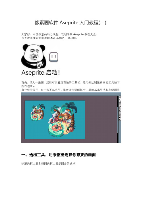
首先,导入一张图,然后可以看到右边的工具栏,是用来绘制像素画的工具如下图右边所示
有一些天天用,有一些不怎么用,我会逐步讲解每个工具的基本用法和高级用法
一、选框工具:用来抠出选择你想要的画面
矩形选框工具和椭圆选框工具是固定的选框
使用后选择画画即可如下拖动
套索工具就是不固定的选框,可以随你心意画框来选择拖动
多边形套索工具是想画方框一样,选择四个点形成多边形,拖动多边形
魔棒工具和大多数绘图工具是一样的功能,可以选择出颜色范围内的同一个颜色区域
下图选择了叶子的做出示范
如果你想快速选择所有同一个范围的颜色,只需要不勾选Contigous就能实现
下图选择了所有叶子的亮色调
二、选区模式
左上角有四个按钮,就是这四个模式
第一个是新选区,新选区只能存在一个,下图就是一个新选区
第二个是添加新选区,这样可以实现选择多个,如下图选择两个人物,可以同时拖动
第三个是删除选区,可以删除你不想要的选区,这个比较简单。
小技巧,在选区中按住Ctrl键,就可以实现复制拖动
第四个是缩小选区,假设你选择了很大的一块,然后想只中间一块
可以使用缩小选区选择
接下来介绍快速选区网络操作的方法,可以看到下图有很多方块
假如你想要这一个格方块,就在这格方块双击一下,就能自动选择当前方块
如何要多选择几格方块,拖动即可。
到这里选区介绍结束,谢谢大家。
Sensor图案自动生成软件指导书
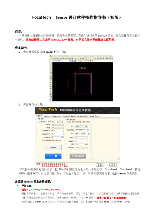
FocalTech Sensor设计软件操作指导书(初版)前言:引导设计人员根据实际的项目,设置各参数配置,直接生成相应的SENSOR图案,提高设计效率及设计一致性。
此自动绘图工具基于AutoCAD2007开发,对于其它版本不能保证其适用性。
准备动作:1.先打开需要设计的Sensor框图,如:2.再打开自动工具:本软件根据不同的设计需求,把SENSOR图案分为七大类:单层互容、GlassSito‐1、GlassSito‐2、传统DITO、超薄DITO、自电容(横三角)、自电容(两点),设计时请根据实际需求,选择Sensor图案类型。
各类型SENSOR图案参数设置:1.单层互容。
适用IC:FT5306i、FT5336i、FT5436i。
根据实际的生产工艺及项目尺寸,填写对应的参数。
填写“尺寸”栏时,工具会根据尺寸自动推荐最佳的通道数量。
当推荐通道数不满足项目需求时,可手动更改“TX数目”与“RX数目”,其中“TX数目”只能为偶数。
参数设置:SENSOR的VA区尺寸,可手动直接输入数值,如:手动输入VA宽度49.96、高度74.44。
如图:也可从CAD获取数值,步骤如下:选择“CAD输入”→点击“获取”→鼠标选中已打开的CAD图→点击SENSOR的VA区左下角及右上角获取数值→返回自动生成软件。
如图:根据实际项目填写外扩值及按键数量,外扩值即允许VA区单边外扩为AA区的尺寸,典型值为单边外扩0.5mm,实际项目中外围空间不足时可设置外扩值为“0”。
根据实际的生产工艺,可进入“扩展参数”子菜单进行详细的工艺设置,如下:其中:走线角度范围:15°—20°,典型值15°。
所有参数填写完毕后,点击“确认”,返回自动生成软件,点击“计算”,计算出图案各参数值,点击“生成图案”,鼠标选中打开的CAD图,点击VA区左下角,等待图案自动生成,如图:2.GlassSito-1。
适用IC:FT5X02系列、FT5X06系列、FT5X16系列,建议适用6.0inch以下尺寸,GlassSito架桥结构。
08 Graphisoft EcoDesigner 用户指南

GRAPHISOFT EcoDesigner用户指南GRAPHISOFT®访问Graphisoft网站获取当地分销商及产品可用性的信息。
GRAPHISOFT EcoDesigner™用户指南版权所有© 2010 GRAPHISOFT,保留所有权利。
在没有预先得到书面许可的情况下,严禁复制,改写以及翻译。
商标ArchiCAD®是GRAPHISOFT的注册商标。
所有其它的商标以及所有权由各自的所有者所有。
目录注释:标题为绿色的章节,为高级用户提供了附加信息。
概述 . . . . . . . . . . . . . . . . . . . . . . . . . . . . . . . . . . . . . . . .7 EcoDesigner工作流程 . . . . . . . . . . . . . . . . . . . . . . . . . . . . . . . .7 ArchiCAD 14 EcoDesigner的新特色及功能的提高 . . . . . . . . . . . . . . . . . . . .8定义 . . . . . . . . . . . . . . . . . . . . . . . . . . . . . . . . . . . . . . . 10 EcoDesigner入门 . . . . . . . . . . . . . . . . . . . . . . . . . . . . . . . . . 18硬件/软件要求 . . . . . . . . . . . . . . . . . . . . . . . . . . . . . . . . . 18文件兼容性 . . . . . . . . . . . . . . . . . . . . . . . . . . . . . . . . . . . 18许可证 . . . . . . . . . . . . . . . . . . . . . . . . . . . . . . . . . . . . . 18安装 . . . . . . . . . . . . . . . . . . . . . . . . . . . . . . . . . . . . . . 19程序文件夹位置 . . . . . . . . . . . . . . . . . . . . . . . . . . . . . . . . . 19卸载 . . . . . . . . . . . . . . . . . . . . . . . . . . . . . . . . . . . . . . 19计算单位设置 . . . . . . . . . . . . . . . . . . . . . . . . . . . . . . . . . . 19局部EcoDesigner内容-XML文件 . . . . . . . . . . . . . . . . . . . . . . . . . 20 EcoDesigner使用的文件夹 . . . . . . . . . . . . . . . . . . . . . . . . . . . . 20与EcoDesigner工作 . . . . . . . . . . . . . . . . . . . . . . . . . . . . . . . . 21自动模型分析 . . . . . . . . . . . . . . . . . . . . . . . . . . . . . . . . . . . 24附加的用户输入 . . . . . . . . . . . . . . . . . . . . . . . . . . . . . . . . . . 25位置和功能 . . . . . . . . . . . . . . . . . . . . . . . . . . . . . . . . . . . 26模型预览 . . . . . . . . . . . . . . . . . . . . . . . . . . . . . . . . . . . . . 35更改批注颜色 . . . . . . . . . . . . . . . . . . . . . . . . . . . . . . . . . . 36修改元素的建筑结构组合 . . . . . . . . . . . . . . . . . . . . . . . . . . . . . 37建筑外壳的绝热墙 . . . . . . . . . . . . . . . . . . . . . . . . . . . . . . . . 37壳板 . . . . . . . . . . . . . . . . . . . . . . . . . . . . . . . . . . . . . . 37选择元素 . . . . . . . . . . . . . . . . . . . . . . . . . . . . . . . . . . . . 39 GRAPHISOFT EcoDesigner用户指南3显示/隐藏建筑体积 . . . . . . . . . . . . . . . . . . . . . . . . . . . . . . . 40自定义建筑体积的显示 . . . . . . . . . . . . . . . . . . . . . . . . . . . . . . 41重新分析模型 . . . . . . . . . . . . . . . . . . . . . . . . . . . . . . . . . . 41返回EcoDesigner . . . . . . . . . . . . . . . . . . . . . . . . . . . . . . . . 42结构 . . . . . . . . . . . . . . . . . . . . . . . . . . . . . . . . . . . . . . . 42建筑外壳元素 . . . . . . . . . . . . . . . . . . . . . . . . . . . . . . . . . . 43表面 . . . . . . . . . . . . . . . . . . . . . . . . . . . . . . . . . . . . . . 45渗透 . . . . . . . . . . . . . . . . . . . . . . . . . . . . . . . . . . . . . . 46 U-值(R-值)计算 . . . . . . . . . . . . . . . . . . . . . . . . . . . . . . . 46 U-值(R-值)计算法则 . . . . . . . . . . . . . . . . . . . . . . . . . . . . . 47热量属性分配 . . . . . . . . . . . . . . . . . . . . . . . . . . . . . . . . . . 49默认热量属性分配 . . . . . . . . . . . . . . . . . . . . . . . . . . . . . . . . 50材料目录 . . . . . . . . . . . . . . . . . . . . . . . . . . . . . . . . . . . . 50自定义材料目录 . . . . . . . . . . . . . . . . . . . . . . . . . . . . . . . . . 51建筑几何图形 . . . . . . . . . . . . . . . . . . . . . . . . . . . . . . . . . . 52内部热存储体块 . . . . . . . . . . . . . . . . . . . . . . . . . . . . . . . . . 53地下隔层 . . . . . . . . . . . . . . . . . . . . . . . . . . . . . . . . . . . . 54地下隔层的高级处理 . . . . . . . . . . . . . . . . . . . . . . . . . . . . . . . 54洞口 . . . . . . . . . . . . . . . . . . . . . . . . . . . . . . . . . . . . . . . 55遮光装置 . . . . . . . . . . . . . . . . . . . . . . . . . . . . . . . . . . . . 58自定义遮光装置 . . . . . . . . . . . . . . . . . . . . . . . . . . . . . . . . . 58洞口目录 . . . . . . . . . . . . . . . . . . . . . . . . . . . . . . . . . . . . 59自定义洞口目录 . . . . . . . . . . . . . . . . . . . . . . . . . . . . . . . . . 61 MEP系统和能量 . . . . . . . . . . . . . . . . . . . . . . . . . . . . . . . . . . 62能量源 . . . . . . . . . . . . . . . . . . . . . . . . . . . . . . . . . . . . . 62热力类型 . . . . . . . . . . . . . . . . . . . . . . . . . . . . . . . . . . . . 63冷却类型 . . . . . . . . . . . . . . . . . . . . . . . . . . . . . . . . . . . . 63通风方式 . . . . . . . . . . . . . . . . . . . . . . . . . . . . . . . . . . . . 64 4GRAPHISOFT EcoDesigner用户指南热水发电 . . . . . . . . . . . . . . . . . . . . . . . . . . . . . . . . . . . . 64内部光源 . . . . . . . . . . . . . . . . . . . . . . . . . . . . . . . . . . . . 65能量成本和电力源 . . . . . . . . . . . . . . . . . . . . . . . . . . . . . . . . 66绿色能源 . . . . . . . . . . . . . . . . . . . . . . . . . . . . . . . . . . . . . 67太阳能采集器 . . . . . . . . . . . . . . . . . . . . . . . . . . . . . . . . . . 67空气间能量回收 . . . . . . . . . . . . . . . . . . . . . . . . . . . . . . . . . 68热泵 . . . . . . . . . . . . . . . . . . . . . . . . . . . . . . . . . . . . . . 68导出到VIP-Energy . . . . . . . . . . . . . . . . . . . . . . . . . . . . . . . . 69 EcoDesigner对话框的功能按钮 . . . . . . . . . . . . . . . . . . . . . . . . . . . 69 VIPCore计算引擎 . . . . . . . . . . . . . . . . . . . . . . . . . . . . . . . . . 70开始评估的条件 . . . . . . . . . . . . . . . . . . . . . . . . . . . . . . . . . . 70计算引擎说明 . . . . . . . . . . . . . . . . . . . . . . . . . . . . . . . . . . . 71计算方法 . . . . . . . . . . . . . . . . . . . . . . . . . . . . . . . . . . . . 71确认 . . . . . . . . . . . . . . . . . . . . . . . . . . . . . . . . . . . . . . 71要获得更多的信息 . . . . . . . . . . . . . . . . . . . . . . . . . . . . . . . . . 72建筑能量评估报告 . . . . . . . . . . . . . . . . . . . . . . . . . . . . . . . . . 73关键值 . . . . . . . . . . . . . . . . . . . . . . . . . . . . . . . . . . . . . . 74能量消耗 . . . . . . . . . . . . . . . . . . . . . . . . . . . . . . . . . . . . . 74碳足迹 . . . . . . . . . . . . . . . . . . . . . . . . . . . . . . . . . . . . . . 75月度能量平衡 . . . . . . . . . . . . . . . . . . . . . . . . . . . . . . . . . . . 75能量供应与排放的类型 . . . . . . . . . . . . . . . . . . . . . . . . . . . . . . . 76自定义能量平衡评估图表的外观 . . . . . . . . . . . . . . . . . . . . . . . . . . . 80评估报告的功能按钮 . . . . . . . . . . . . . . . . . . . . . . . . . . . . . . . . 82 GRAPHISOFT EcoDesigner用户指南56GRAPHISOFT EcoDesigner用户指南概述Graphisoft EcoDesigner是ArchiCAD 14的插件应用程序,它允许建筑师依靠建筑几何分析、建筑物位置每一个小时的气象资料、以及直接的用户输入,对ArchiCAD内的建筑物进行能量估算。
- 1、下载文档前请自行甄别文档内容的完整性,平台不提供额外的编辑、内容补充、找答案等附加服务。
- 2、"仅部分预览"的文档,不可在线预览部分如存在完整性等问题,可反馈申请退款(可完整预览的文档不适用该条件!)。
- 3、如文档侵犯您的权益,请联系客服反馈,我们会尽快为您处理(人工客服工作时间:9:00-18:30)。
FocalTech Sensor设计软件操作指导书(初版)
前言:
引导设计人员根据实际的项目,设置各参数配置,直接生成相应的SENSOR图案,提高设计效率及设计一致性。
此自动绘图工具基于AutoCAD2007开发,对于其它版本不能保证其适用性。
准备动作:
1.先打开需要设计的Sensor框图,如:
2.再打开自动工具:
本软件根据不同的设计需求,把SENSOR图案分为七大类:单层互容、GlassSito‐1、GlassSito‐2、传统DITO、超薄DITO、自电容(横三角)、自电容(两点),设计时请根据实际需求,选择Sensor图案类型。
各类型SENSOR图案参数设置:
1.单层互容。
适用IC:FT5306i、FT5336i、FT5436i。
根据实际的生产工艺及项目尺寸,填写对应的参数。
填写“尺寸”栏时,工具会根据尺寸自动推荐最佳的通道数量。
当推荐通道数不满足项目需求时,可手动更改“TX数目”与“RX数目”,其中“TX数目”只能为偶数。
参数设置:SENSOR的VA区尺寸,可手动直接输入数值,如:手动输入VA宽度49.96、高度74.44。
如图:
也可从CAD获取数值,步骤如下:选择“CAD输入”→点击“获取”→鼠标选中已打开的CAD图→点击SENSOR的VA区左下角及右上角获取数值→返回自动生成软件。
如图:
根据实际项目填写外扩值及按键数量,外扩值即允许VA区单边外扩为AA区的尺寸,典型值为单边外扩0.5mm,实际项目中外围空间不足时可设置外扩值为“0”。
根据实际的生产工艺,可进入“扩展参数”子菜单进行详细的工艺设置,如下:
其中:走线角度范围:15°—20°,典型值15°。
所有参数填写完毕后,点击“确认”,返回自动生成软件,点击“计算”,计算出图案各参数值,点击“生成图案”,
鼠标选中打开的CAD图,点击VA区左下角,等待图案自动生成,如图:
2.GlassSito-1。
适用IC:FT5X02系列、FT5X06系列、FT5X16系列,建议适用6.0inch以下尺寸,GlassSito架桥结构。
(6.0inch或以上项目时,需要在生成图案的基础上增加dummy。
此自动工具暂不支持,需要手工增加dummy。
)
与单层互容一样,可手动输入或从CAD获取VA区数值,输入实际外扩数值,根据选用的IC输入TX和RX数目,根据实际生产工艺,输入各参数值a、b、c、d、e、Bw、Ew、Tw,点击“生成图案”,鼠标选中打开的CAD图,点击VA区左下角,等待图案自动生成,如图:
3.GlassSito-2
适用IC:FT5336、FT5X26系列,Glass架桥结构。
因此类IC为TX数量少于RX数量,所以在生成此图案时,须将VA区横向放置。
与单层互容一样,可手动输入或从CAD获取VA区数值,根据选用的IC输入TX和RX数目,根据实际生产工艺输入参数C数值(线距),点击“生成图案”,鼠标选中打开的CAD图,点击VA区左下角,等待图案自动生成,如图:
4.传统DITO
适用IC:FT5X02、FT5X06、FT5606、FT5816。
与单层互容一样,可手动输入或从CAD获取VA区数值,输入实际外扩数值,根据选用的IC输入TX和RX数目,根据工艺要求输入Gap值、RX有效宽度、RX桥宽,点击“生成图案”,鼠标选中打开的CAD图,点击VA区左下角,等待图案自动生成,如图:
5.超薄DITO。
适用IC:敦泰所有的互电容系列。
因此类图案是基于TX数量少于RX数量的IC开发的,所以生成时须将VA横向放置。
与单层互容一样,可手动输入或从CAD获取VA区数值,输入实际外扩数值,根据选用的IC输入TX和RX数目,根据实际工艺输入参数a、c、d、e,点击“生成图案”,鼠标选中打开的CAD图,点击VA区左下角,等待图案自动生成,如图:
6.自电容(横三角)。
适用IC:FT6X06。
与单层互容一样,可手动输入或从CAD获取VA区数值,输入VA区不同边沿的外扩数值,根据选用的IC输入通道数,根据实际工艺输入参数d、e、最小线宽、最小线距、BondingPAD偏移值,点击“生成图案”,鼠标选中打开的CAD图,点击VA区左下角,等待图案自动生成,如图:
适用IC:FT6306。
与单层互容一样,可手动输入或从CAD获取VA区数值,输入VA区不同边沿的外扩数值,根据选用的IC输入通道数,根据实际工艺输入三角形尖端宽度,点击“生成图案”,鼠标选中打开的CAD图,点击VA区左下角,等
待图案自动生成,如图:
我们将持续改进,感谢关注!。
