亚德客DMSG说明书
亚德客真空负压表说明书
亚德客真空负压表说明书
•亚德客真空负压表说明书
1、量测模式请按住键3 秒后进入OUT1 操作模式。
2、OUT1 操作模式请按或键选择OPS 模式,按进入OUT1 状态设置。
3、OUT1 状态设置请按或键选择NC 模式,按进入OUT2 操作模式。
4、OUT2 操作模式请按或键选择OFF 模式,按进入反应时间设置。
5、反应时间设置请按或键选择2.5 秒,按进入背光控制设置。
6、背光控制设置请按或键选择SOG 模式,按进入单位设置。
7、单位设置请按或键选择PR 模式,按返回量测模式。
8、量测模式请按一次,会交替地显示出设定值和"P-1" ;请按或键设定-60kpa。
MPS说明书

第 9 页 共 72 页
亚德客(中国)有限公司
模块在收到前一站发送的启动信息后,从第一步开始执行,直至最后一步;向下 一站发出工件的颜色与材料信息并通知前来取料,同时通知前一站允许放料;然 后返回第一步继续执行,或等到按下停止按钮。 第四站(气动机械手、输送带工作站)
亚德客(中国)有限公司
Modular Production System(MPS) 模块式自动生产系统
使用说明书
MANUAL
亚德客(中国)有限公司
第 1 页 共 72 页
亚德客(中国)有限公司
目录
一、 产品概述..................................................................... 3 二、 工作参数及常规安全说明.......................................... 4 三、 系统组成:................................................................. 5 四、 设备操作流程说明..................................................... 6 五、 气动........................................................................... 13 六、 电子........................................................................... 15 七、 控制........................................................................... 17 八、 常见故障现象及处理办法........................................ 18 九、 附录........................................................................... 20
气缸使用说明书

气缸使用说明书说明书的适用范围本产品使用说明书是按气缸在一般气动系统中做为执行元件应用的情况下编写的因此适用于普通单杆双(单)作用、带缓冲的、无油润滑的耐高温的各种规格的标准气缸和在普通标准气缸基础上修改设计的非标气缸。
本“说明书”与各型号气缸“产品样本”合用其各型号气缸的特点、技术参数、外型安装尺寸详见“产品样本”。
一、气缸使用条件1、气缸使用系统压力、介质温度应符合各型号气缸基本参数表规定的数值(见产品样本)。
2、驱动气缸的压缩空气必须清洁、水分少、为此在气动系统回路中必须使用分水过滤器。
3、为了润滑气缸内部在气动系统回路中必须安装使用油雾器(无油润滑气缸可不用油雾器)。
二、气缸安装使用l、气缸开箱安装前应检查气缸在运输过程中有无损坏两端拉杆螺母或螺纹连接处有无松动清除防锈油及防护罩(帽)方可安装使用。
2、气缸安装时应注重气缸活塞杆不宜承受偏心载荷或横向载荷应使载荷的运动方向与活塞杆轴心线一致对于长行程气缸负载和活塞杆的连接最好采用可活动的U型接头或关节接头。
无论任何安装方式都必须保证气缸安装底座有足够的刚度。
3、气缸缸体在水平使用时可用“三点法”进行检验。
首选使活塞杆与负载相连接。
当活塞杆全部伸出时在杆的中间放一水准仪观察水平情况;其次当活塞杆处于中间位置时在靠近气缸前端盖处的活塞杆上放一水准仪观察情况;最后活塞杆处于退回位置时应无别劲现象。
长行程气缸卧式安装时为了防止活塞杆下垂、缸筒变形须设置适当支承。
4、采用前后法兰、脚架式安装的气缸应避免装螺栓直接承受推力或拉力的负荷。
5、采用尾部单双耳的气缸或中间摆动气缸时活塞杆顶端连接销位置应与安装件轴的位置处于同一方向。
尾部单双耳或摆动轴应与安装架之间留有合适间隙。
6、气缸安装完毕后应在无负载状态下使用工作压力运行2-5次检查气缸口部有无异常现象。
7、气缸调速,对气缸运动速度有一定要求时气动系统必须安装单向节流闹。
一般情况气缸水平安装排气节流气缸速度比较平稳。
亚德客磁性开关DMSG说明书

亚德客磁性开关DMSG说明书电磁阀选型首先应该依次遵循安全性,可靠性,适用性,经济性四大原则,其次是根据六个方面的现场工况(即管道参数、流体参数、压力参数、电气参数、动作方式、特殊要求进行选择)。
选型依据:一、根据管道参数选择电磁阀的:通径规格(即)、接口方式、按照现场管道内径尺寸或流量要求来确定通径()尺寸。
接口方式,一般>要选择法兰接口,≤则可根据用户需要自由选择。
二、根据流体参数选择电磁阀的:材质、温度组、腐蚀性流体:宜选用耐腐蚀电磁阀和全不锈钢;食用超净流体:宜选用食品级不锈钢材质电磁阀。
高温流体:要选择采用耐高温的电工材料和密封材料制造的电磁阀,而且要选择活塞式结构类型的。
流体状态:大至有气态,液态或混合状态,特别是口径大于订货时一定要区分开来。
流体粘度:通常在以下可任意选择,若超过此值,则要选用高粘度电磁阀。
三、根据压力参数选择电磁阀的:原理和结构品种、公称压力:这个参数与其它通用阀门的含义是一样的,是根据管道公称压力来定。
") 、工作压力:如果工作压力低则必须选用直动或分步直动式原理;最低工作压差在以上时直动式、分步直动式、先导式均可选用。
四、电气选择:电压规格应尽量优先选用、较为方便。
五、根据持续工作时间长短来选择:常闭、常开、或可持续通电当电磁阀需要长时间开启,并且持续的时间多余关闭的时间应选用常开型。
要是开启的时间短或开和关的时间不多时,则选常闭型。
但是有些用于安全保护的工况,如炉、窑火焰监测,则不能选常开的,应选可长期通电型。
六、根据环境要求选择辅助功能:防爆、止回、手动、防水雾、水淋、潜水、爆炸性环境:必须选用相应防爆等级的电磁阀.当管内流体有倒流现象时,可选择带止回功能电磁阀。
当需要对电磁阀进行现场人工操作时,可选择带手动功能电磁阀。
露天安装或粉尘多场合应选用防水,防尘品种(防护等级在以上)。
用于喷泉必须采用潜水型电磁阀(防护等级在以上)。
亚德客dmsg020说明书
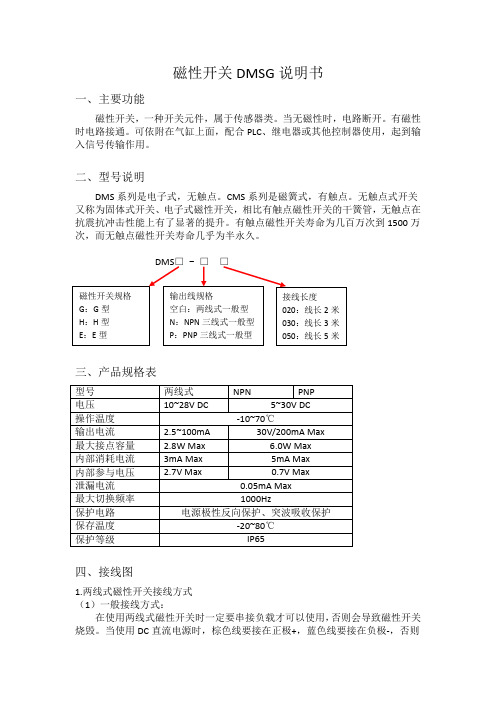
磁性开关DMSG说明书一、主要功能磁性开关,一种开关元件,属于传感器类。
当无磁性时,电路断开。
有磁性时电路接通。
可依附在气缸上面,配合PLC、继电器或其他控制器使用,起到输入信号传输作用。
二、型号说明DMS系列是电子式,无触点。
CMS系列是磁簧式,有触点。
无触点式开关又称为固体式开关、电子式磁性开关,相比有触点磁性开关的干簧管,无触点在抗震抗冲击性能上有了显著的提升。
有触点磁性开关寿命为几百万次到1500万次,而无触点磁性开关寿命几乎为半永久。
三、产品规格表四、接线图1.两线式磁性开关接线方式(1)一般接线方式:在使用两线式磁性开关时一定要串接负载才可以使用,否则会导致磁性开关烧毁。
当使用DC直流电源时,棕色线要接在正极+,蓝色线要接在负极-,否则指示灯不会亮。
(2)串联接线方式:在串联使用磁性开关时,要注意磁性开关内部压降亦相加,每一个磁性开关内部压降约为2.5V。
当串联过多的磁性开关时,磁性开关的总内部压降会过大,将可能使负载无法启动。
可串联的开关数量因电源电压而异。
(3)并联接线方式:在并联使用磁性开关时,若开关同时动作,流过磁性开关的电流会因分流而减小。
当并联过多的磁性开关时,流过磁性开关的电流可能过小,会使开关的指示灯微亮或不亮,可并联的开关数量因负载电流而异。
2.三线式无触点NPN型磁性开关接线方式(1)一般接线方式:在使用三线式磁性开关时,一定要使用DC直流电源,注意黑色线的接法,错接会导致开关烧毁。
棕色线要接在正极+,蓝色线要接负极-,黑色线串接负载后再接入正极+。
(2)并联接线方式:在并联使用磁性开关时,并不影响磁性开关的动作即负载输出,但微量的输出漏电流将会增加。
当并联过多的磁性开关时,且负载的电流过小,将可能使负载输出而误动作,可并联的开关数量因负载电流而异。
3. 三线式无触点PNP型磁性开关接线方式(1)一般接线方式:在使用三线式磁性开关时,一定要使用DC直流电源,注意黑色线的接法,错接会导致开关烧毁。
亚德客真空压力表 说明书

亚德客真空压力表说明书
1、压力表在防治的时候必须垂直放置:在安装的时候要用扳手">扳手旋紧,不要直接去用手拧其外表壳,因为这样会使其表壳受到破坏。
在运输的时候不要让它发生碰撞,以免发生损坏。
2、在使用压力表的时候,要注意将其振幅控制在一毫米以下。
3、在使用过程中,如果因为环境中的温度太高而出现仪表的指针不能归零的现象,那么可以将表壳上面的橡胶塞剪开,使大气进入仪表内部就可以轻松的解决这个问题了。
4、仪表在使用的时候,要注意外界的温度,要将外界环境温度控制在-25到55度。
只有在这个温度范围内才能保证压力表正常工作,不受损伤。
5、压力表使用中要定期的进行检查,检查的周期是至少每三个月检查一次,在检查中如果发现了任何故障都应该及时的修理。
6、压力表使用也是有一定的范围,这个范围应该控制在压力表最大值的三分之一到三分之二之间的范围内。
7、如果在压力表出厂半年内,因为压力表本身的质量问题所造成的损失应该由其公司负责。
台湾亚德客电磁阀使用说明
台湾【亚德客电磁阀】使用说明
1、使用前注意检查组件在运输过程中是否损坏,然后安装使用;
2、安装时请注意气体流动方向及接管牙型是否正确,使用介质必须经过40um
滤芯过滤;
3、请注意安装条件是否符合技术要求(如“电压”、“作动频率”、“工作压力”、
“使用温度范围”等),然后安装使用;
4、安装时注意气体流动方向,P为进气口,A(B)为工作口、R(S)为排气口;
5、尽量避免在震动的环境下使用,并注意低温下的防冻措施;
6、连接管路时,注意止泄带缠绕不可超过接头牙端面,注意清除管路接头内的
粉尘、铁屑等杂物,避免杂质或异物进入阀体内;
7、请注意防尘,建议排气口安装消声器或消声节流阀,拆下来不用时应在进、
出口装防尘套;
8、整机调试时,建议先用手动装置调试,然后在通电调试。
以上便是就台湾亚德客电磁阀安装使用进行的一系列说明,希望对您有所帮助!文章来自于济南元元利富科贸有限公司,如有需要欢迎拨打4006589919或者登录,我们将竭诚为您服务!。
DPG 1200 SERIES Digital Pressure Gauge 操作说明说明书

e-mail:**************For latest product manuals:DPG 1200 SERIESDigital Pressure GaugeShop online atUser’s Guide/Omega-DPG1200-Pressure-Testers.aspxTo buy, sell, rent or trade-in this product please click on the link below:Model 1200, 1202, 1203 and 1205DIGITAL PRESSURE GAUGE OPERATING INSTRUCTION_______________________________________________Operating / Mounting Instructions1.Mount the gauge on a suitable _” (or appropriately sized) NPT female fittings. Use Teflon tape or pipedope to seal threads. Do not over tighten.2.Depress ON/OFF button to power up unit (no pressure applied). If there is a reading other than zero,press the ZERO button to zero-out the display.3.Apply pressure to the gauge – the display should now indicate that pressure is being applied.Note: If the ZERO Button is pressed when the pressure is changing, the display will not indicate “0”until the pressure has stabilized or by reducing the system pressure back to “0” (no pressure applied).Press the ZERO button to zero-out the display once pressure has been stabilized.4.Press the ON/OFF button to shut off display.Note: The display will automatically turn off after approximately 3 minutes.5.Battery Replacement: The battery is located on the inside of the rear cover. Remove one screw toremove the rear cover. Using a small screwdriver to slide the battery out, un-snap the old 9V batteryand replace with the new battery. Replace the rear cover and the screw when complete.Caution:Do not hold down the ON/OFF button for more than 5 seconds. This could affect the calibration of the gauge.Settings Glossary:Continuous reading: the gauge display constantly shows the current readingPeak and Hold: the gauge displays the maximum recorded pressure during a specified time period or sessionAon: the gauge will be set to stay on for a maximum of 15 minutesAoff:the gauge will be set to stay on for only 3 minutesMaximum Over Pressure Limit: the maximum amount of pressure the gauge will display beyond the gauge's specified rangeMinimum under pressure Limit: the lower limit that the gauge will display beyond zeroIt is the policy of OMEGA Engineering, Inc. to comply with all worldwide safety and EMC/EMI regulations that apply. OMEGA is constantly pursuing certification of its products to the European New Approach Directives. OMEGA will add the CE mark to every appropriate device upon certification.The information contained in this document is believed to be correct, but OMEGA accepts no liability for any errors it contains, and reserves the right to alter specifications without notice.WARNING: These products are not designed for use in, and should not be used for, human applications.WARRANTY/DISCLAIMEROMEGA ENGINEERING, INC. warrants this unit to be free of defects in materials and workmanship for a period of 13 months from date of purchase.OMEGA’s WARRANT Y adds an additional one (1) month grace period to the normal one (1) year product warranty to cover handling and shipping time. This ensures that OMEGA’s customers receive maximum coverage on each product.If the unit malfunctions, it must be returned to the factory for evaluation. OMEGA’s Customer Service Department will issue an Authorized Return (AR)number immediately upon phone or written request. Upon examination by OMEGA, if the unit is found to be defective, it will be repaired or replaced at no charge. OMEGA’s WARRANTY does not apply to defects resulting from any action of the purchaser, including but not limited to mishandling,improper interfacing, operation outside of design limits, improper repair, or unauthorized modification. This WARRANTY is VOID if the unit shows evidence of having been tampered with or shows evidence of having been damaged as a result of excessive corrosion; or current, heat, moisture orvibration; improper specification; misapplication; misuse or other operating conditions outside of OMEGA’s control. Components in which wear is not warranted, include but are not limited to contact points, fuses, and triacs.OMEGA is pleased to offer suggestions on the use of its various products. However, OMEGA neither assumes responsibility for any omissions or errors nor assumes liability for any damages that result from the use of its products in accordance with information provided by OMEGA, either verbal or written. OMEGA warrants only that the parts manufactured by the company will be as specified and free of defects. OMEGA MAKES NO OTHER WARRANTIES OR REPRESENTATIONS OF ANY KIND WHATSOEVER, EXPRESSED OR IMPLIED, EXCEPT THAT OF TITLE, AND ALL IMPLIED WARRANTIES INCLUDING ANY WARRANTY OF MERCHANTABILITY AND FITNESS FOR A PARTICULAR PURPOSE ARE HEREBY DISCLAIMED. LIMITATION OF LIABILITY : The remedies of purchaser set forth herein are exclusive, and the total liability of OMEGA with respect to this order, whether based on contract, warranty, negligence, indemnification, strict liability or otherwise,shall not exceed the purchase price of the component upon which liability is based. In no event shall OMEGA be liable for consequential,incidental or special damages.CONDITIONS: Equipment sold by OMEGA is not intended to be used, nor shall it be used: (1) as a “Basic Component” under 10 CFR 21 (NRC), used in or with any nuclear installation or activity; or (2) in medical applications or used on humans. Should any Product(s) be used in or with any nuclear installation or activity, medical application, used on humans, or misused in any way, OMEGA assumes no responsibility as set forth in our basic WARRANT Y/DISCLAIMER language, and, additionally, purchaser will indemnify OMEGA and hold OMEGA harmless from any liability or damage whatsoever arising out of the use of the Product(s) in such a manner.Servicing North America:U.S.A.:One Omega Drive, Box 4047ISO 9001 CertifiedStamford, CT 06907-0047Tel: (203) 359-1660FAX: (203) 359-7700e-mail:**************Canada:976 BergarLaval (Quebec) H7L 5A1, Canada Tel: (514) 856-6928FAX: (514) 856-6886e-mail:*************For immediate technical or application assistance:U.S.A. and Canada:Sales Service: 1-800-826-6342 / 1-800-TC-OMEGA ®Customer Service: 1-800-622-2378 / 1-800-622-BEST ®Engineering Service: 1-800-872-9436 / 1-800-USA-WHEN ®AMexico:En Espan ˜ol: (001) 203-359-7803e-mail:*****************FAX: (001) 203-359-7807**************.mxOMEGAnet ®Online Service Internet e-mailo mega.c o m inf o @o mega.c o mServicing Europe:Benelux:Postbus 8034, 1180 LA Amstelveen, The NetherlandsTel: +31 (0)20 3472121FAX: +31 (0)20 6434643Toll Free in Benelux: 0800 0993344e-mail:*****************Czech Republic:Frystatska 184, 733 01 Karviná, Czech Republic Tel: +420 (0)59 6311899FAX: +420 (0)59 6311114Toll Free: 0800-1-66342e-mail:*****************France:11, rue Jacques Cartier, 78280 Guyancourt, France Tel: +33 (0)1 61 37 2900FAX: +33 (0)1 30 57 5427Toll Free in France: 0800 466 342e-mail:**************Germany/Austria:Daimlerstrasse 26, D-75392 Deckenpfronn, GermanyTel: +49 (0)7056 9398-0FAX: +49 (0)7056 9398-29TollFreeinGermany************e-mail:*************United Kingdom:One Omega Drive, River Bend Technology CentreISO 9002 CertifiedNorthbank, Irlam, Manchester M44 5BD United Kingdom Tel: +44 (0)161 777 6611FAX: +44 (0)161 777 6622Toll Free in United Kingdom: 0800-488-488e-mail:**************.ukM4228/0705RETURN REQUESTS /INQUIRIESDirect all warranty and repair requests/inquiries to the OMEGA Customer Service Department. BEFORE RET URNING ANY PRODUCT(S) T OOMEGA, PURCHASER MUST OBTAIN AN AUTHORIZED RETURN (AR) NUMBER FROM OMEGA’S CUSTOMER SERVICE DEPARTMENT (IN ORDER T O AVOID PROCESSING DELAYS). T he assigned AR number should then be marked on the outside of the return package and on any correspondence.The purchaser is responsible for shipping charges, freight, insurance and proper packaging to prevent breakage in transit.FOR WARRANTY RETURNS, please have the following information available BEFORE contacting OMEGA:1.Purchase Order number under which the product was PURCHASED,2.Model and serial number of the product under warranty, and3.Repair instructions and/or specific problems relative to the product.FOR NON-WARRANTY REPAIRS,consult OMEGA for current repair charges.Have the following information available BEFORE contacting OMEGA:1. Purchase Order number to cover the COST of the repair,2.Model and serial number of the product, and3.Repair instructions and/or specific problems relative to the product.OMEGA’s policy is to make running changes, not model changes, whenever an improvement is possible. T his affords our customers the latest in technology and engineering.OMEGA is a registered trademark of OMEGA ENGINEERING, INC.© Copyright 2005 OMEGA ENGINEERING, INC. All rights reserved. This document may not be copied, photocopied, reproduced, translated, or reduced to any electronic medium or machine-readable form, in whole or in part, without the prior written consent of OMEGA ENGINEERING, INC.。
rexroth AG直动式方向阀说明书

RE 22280, edition: 2013-06, Bosch Rexroth AGDirectional spool valves, direct operated, with mechanical or manual actuationFeatures ▶4/3, 4/2 or 3/2 directional design▶Porting pattern according to DIN 24340 form A (without locating hole)▶Porting pattern according to ISO 4401-03-02-0-05 andNFPA T3.5.1 R2-2002 D03 (with locating hole)▶Types of actuation:–Roller plunger–Hand lever–Rotary knob▶Inductive position switches and proximity sensors(contactless)ContentsF eatures 1Ordering code2, 3Symbols 4Types of actuation 5Function, section 6Technical data 7Actuating force/torque 8Characteristic curves 8Performance limits 9, 10Dimensions 11 … 13More information 14 ▶Size 6▶Component series 5X; 6X▶Maximum operating pressure 315 [4569 psi]▶Maximum flow 60 l/min [15.8 US gpm]RE 22280 Edition: 2013-06Replaces: 04.10H7114Type WMR, WMRZ, WMU, WMM and WMD(A)2/14WMR, WMRZ, WMU, WMM, WMD(A) | Directional spool valveBosch Rexroth AG , RE 22280, edition: 2013-06Ordering code 3 main ports34 main ports 4Type of actuation 02Roller plunger (see page 12)WMR Roller plunger (see page 12)WMRZ Roller plunger (see page 12)WMU Hand lever WMM Rotary knobWMD Lockable rotary knob 1)WMDA 03Size 6604Symbols e.g. C, E, EA, EB, etc; possible version see pages 4 and 505Component series 50 to 59 (50 to 59: Unchanged installation and connection dimensions)5X Component series 60 to 69 (60 to 69: Unchanged installation and connection dimensions) (only version "WMRZ")6X 06With spring return (version "WMR", "WMRZ", "WMU", "WMM")no codeWithout spring return with detent (version "WMM", "WMD", "WMDA")FCorrosion protection 07Standard corrosion protection no codeImproved corrosion protection 2)JSpool position monitoring 3)08Without position switchno code – Inductive position switch type QM Monitored spool position "a"QMAG24Monitored spool position "b"QMBG24Monitored rest positionQM0G24For more information see data sheet 24830010203040506070809101112136//*1) Key with material no. R900006980 for series 50 to 52 andR900008158 from series 53 is included in the scope of delivery.2)The external parts made of metal are galvanized, treated with an anti-corrosion agent or made of stainless steel. This design is also suitable for on-wall applications.3) Only for valves with 2 spool positions such as versions "WMR", "WMU" and "WMM"; not for version "J"4) Use if volume flow > performance limit of the valve, effective in channel P.5)Locking pin ISO 8752-3x8-St, material no. R900005694, separate orderDirectional spool valve | WMR, WMRZ, WMU, WMM, WMD(A) 3/14RE 22280, edition: 2013-06, Bosch Rexroth AGOrdering code010203040506070809101112136//*09Without throttle insert no code Throttle Ø 0.8 mm [0.0315 inch]B08 4) Throttle Ø 1.0 mm [0.0394 inch]B10 4) Throttle Ø 1.2 mm [0.0472 inch]B12 4)Clamping length 1042 mm [1.65 inch] (standard)no code22 mm [0.87 inch] (only version "WMRZ")ZSeal material 11NBR seals no codeFKM sealsV Attention: Observe compatibility of seals with hydraulic fluid used! (Other seals upon request)12Without locating hole no code With locating hole/60 5)With locating hole and locking pin ISO 8752-3x8-St /6213Further details in the plain text= A = C = D= B 2)= Y 2)= R = T = U = V = W= P= Q = L = M= E 1)= F = G = H = J = E1-3)= .B 1)= .A 1)A BPT a0a0A B P T A B P T 0b0bA B P T A BP Ta0a0A B P Tbb 4/14WMR, WMRZ, WMU, WMM, WMD(A) | Directional spool valveBosch Rexroth AG , RE 22280, edition: 2013-06Symbols1)Example:Symbol E with spool position "a" → ordering code ..EA ..Symbol E with spool position "a" → ordering code ..EB ..2)Only version "WMR", "WMU" and "WMM"3)Symbol E1-: P → A/B pre-openingCaution in conjunction with differential cylinders due to pressure intensification!Directional spool valve | WMR, WMRZ, WMU, WMM, WMD(A) 5/14RE 22280, edition: 2013-06, Bosch Rexroth AG1)See symbols on page 42) Only for valves with 2 spool positionsTypes of actuation(P)(P)(P)P6/14WMR, WMRZ, WMU, WMM, WMD(A) | Directional spool valveBosch Rexroth AG , RE 22280, edition: 2013-06Function, sectionType WM.. valves are mechanical, manually actuated direc-tional spool valves. They control the start, stop and direc-tion of a flow.Directional valves basically consist of housing (1), one type of actuation (2) (roller plunger, hand lever, rotary knob), control spool (3), and one or two return springs (4).In de-energized state, the return springs (4) maintain the control spool (3) in central or starting position - if the rotary knob is actuated with a detent.The control spool (3) is moved to the desired spool posi-tion by means of the type of actuation (2).DetentDirectional valves with rotary knob are generally designed with detent. Directional valves with hand lever are option-ally available as 2 or 3 position valves with detent. Direc-tional valves with roller plunger are generally designed without detent. If types of actuation with detent are used, each spool position can be locked, depending on the valve type.Throttle insertThe use of a throttle insert is required when due to prevail-ing operating conditions, flows can occur during theswitching processes, which exceed the performance limit of the valve.It is inserted in channel P of the directional valve.Type 4WMR 6 E5X/…Type 4WMM 6 D5X/FType 4WM. 6 ..5X/..B..Type 4WMRZ 6 D6X/…Directional spool valve | WMR, WMRZ, WMU, WMM, WMD(A) 7/14RE 22280, edition: 2013-06, Bosch Rexroth AGTechnical data(for applications outside these parameters, please consult us!)1)The cleanliness classes specified for the components must be adhered to in hydraulic systems. Effective filtrationprevents faults and at the same time increases the life cycle of the components.For the selection of the filters see /filter.Hydraulic fluidClassificationSuitable sealing materials StandardsMineral oils HL, HLP, HLPD, HVLP, HVLPD NBR, FKM DIN 51524Bio-degradable– insoluble in water HETG NBR, FKM VDMA 24568HEES FKM – soluble in water HEPG FKM VDMA 24568Flame-resistant– water-freeHFDU, HFDRFKM ISO 12922– containing waterHFC (Fuchs Hydrotherm 46M, Petrofer Ultra Safe 620)NBR, HNBRISO 12922fluids refer to data sheet 90220 or contact us!▶There may be limitations regarding the technical valve data (temperature, pressure range, life cycle, maintenance inter-vals, etc.)!▶The flash point of the hydraulic fluid used must be 40 K higher than the maximum solenoid surface temperature.▶Flame-resistant – containing water :–Maximum pressure difference per control edge 50 bar–Pressure pre-loading at the tank port > 20% of the pressure differential, otherwise increased cavitation–Life cycle as compared to operation with mineral oil HL, HLP 50 to 100%8/14WMR, WMRZ, WMU, WMM, WMD(A) | Directional spool valveBosch Rexroth AG , RE 22280, edition: 2013-06Calculation formula for the actuating force (F R ) at the roller plunger in case of tank pressure: F R = F without tank pressure + p T x 1.4 N/barActuating force/torqueCharacteristic curves(measured with HLP46, ϑoil = 40 ± 5 °C [104 ± 9 °F])SymbolsDirection of flow P–AP–B A–T B–T A 33––B 33––C 1131D 5533E 3311F 1311G 6699H 2422J 1121L 3349M 2433P3111Q 1121R 554–T 101099U 3394V 1211W 1122Y55337Symbol "R" in spool position "b" (A → B)8Symbols "G" and "T" in central position (P → T)∆p -q V characteristic curvesP r e s s u r e d i f f e r e n t i a l i n b a r [p s i ] →Flow in l/min [US gpm] →100220030061735483150204060305010[0][4][8][12][2][6][10][14][0][4000][1000][2000][3000][4569]3150204060305010[0][4][8][12][2][6][10][14]1001200300354[0][4000][1000][2000][3000][4569]2Directional spool valve | WMR, WMRZ, WMU, WMM, WMD(A) 9/14RE 22280, edition: 2013-06, Bosch Rexroth AGPerformance limits(measured with HLP46, ϑoil = 40 ± 5 °C [104 ± 9 °F])O p e r a t i n g p r e s s u r e i n b a r [p s i ] →Flow in l/min [US gpm] →Version "WMR", "WMRZ", "WMU"CharacteristiccurveSymbol 1A, B2C, D, Y, E, E1–, H, M,Q, U, W3F, P 4G 5J, L 6R 8V 7TO p e r a t i n g p r e s s u r e i n b a r [p s i ] →Flow in l/min [US gpm] →Version "WMM" - spring returnCharacteristiccurveSymbol1E, E1–, M, J, L, Q, U, W, C, D, Y, G, H, R2A, B 3V 4F, P 5T204060305010[0][4][8][12][2][6][10][14]31510082003006173549[0][4000][1000][2000][3000][4569]3, 523150204060305010[0][4][8][12][2][6][10][14]10022003006173548[0][4000][1000][2000][3000][4569]4, 510/14WMR, WMRZ, WMU, WMM, WMD(A) | Directional spool valveBosch Rexroth AG , RE 22280, edition: 2013-06Performance limits(measured with HLP46, ϑoil = 40 ± 5 °C [104 ± 9 °F])O p e r a t i n g p r e s s u r e i n b a r [p s i ] →Version "WMD", "WMDA"CharacteristiccurveSymbol1E, E1–, M, H, C, D, Y,Q, U, W2J, L 3A, B 4G, P 5F 6V 7R 8TFlow in l/min [US gpm] →O p e r a t i n g p r e s s u r e i n b a r [p s i ] →Version "WMM" - with detentCharacteristiccurveSymbol 1E1–, M, H, C, D, Y 2E, J, Q, L, U, W3A, B 4G, T 5F 6V 7P 8R 9TFlow in l/min [US gpm] →Directional spool valve| WMR, WMRZ, WMU, WMM, WMD(A) 11/14 Dimensions(dimensions in mm [inch])Version "WMM"Version "WMD"1Name plate2Porting pattern according to DIN 24340 form A (without locating hole), ISO 4401-03-02-0-05 andNFPA T3.5.1 R2-2002 D03 (with locating hole for locking pin ISO 8752-3x8-St, material no. R900005694, separate order) 3Identical seal rings for ports A, B, P and T5Valve with 2 spool positions6Valve with 3 spool positions Version "WMM"7Spool position "a"8Spool position "b"9Spool position "0", "a" and "b" (a and b for valves with2 spool positions)Version "WMD", "WMDA"10Spool position "a"11Spool position "0" and "b" (b for valves with 2 spool positions) 12Spool position "b"13Switching angle 90° right and 90° left (for valves with 3 spool positions)14111212/14WMR, WMRZ, WMU, WMM, WMD(A) | Directional spool valveVersion "WMR"Version "WMU"Version "WMR", "WMU"Version "WMRZ"Dimensions(dimensions in mm [inch])1Name plate2Porting pattern according to DIN 24340form A (without locating hole),ISO 4401-03-02-0-05 andNFPA T3.5.1 R2-2002 D03 (withlocating hole for locking pinISO 8752-3x8-St, materialno. R900005694, separate order)3Identical seal rings for ports A, B,P and T4Alternative clamping length (): 22 mm(only version "WMRZ")Version "WMR", "WMRZ", "WMU"5Valve with 2 spool positions6Valve with 3 spool positions10Spool position "a"11Spool position "0" and "b" (b forvalves with 2 spool positions)12Spool position "b"14Excessive stroke, cannot be used asworking stroke15Spool position "a" or "b"16Spool position "0"17Actuation on side B (depending onthe piston)Subplates and valve mounting screwssee page 13.Directional spool valve| WMR, WMRZ, WMU, WMM, WMD(A) 13/14 DimensionsSubplates according to data sheet 45052 (separate order) (without locating hole) G 341/01 (G1/4)G 342/01 (G3/8)G 502/01 (G1/2)(with locating hole) G 341/60 (G1/4)G 342/60 (G3/8)G 502/60 (G1/2)G 341/12 (SAE-6) 1)G 342/12 (SAE-8) 1)G 502/12 (SAE-10) 1)1) Upon request Valve mounting screws (separate order)▶Clamping length 42 mm:4 metric hexagon socket head cap screwsISO 4762 - M5 x 50 - 10.9-flZn-240h-L(friction coefficient µges = 0.09 to 0.14);tightening torque M A = 7 Nm [5.2 ft-lbs] ± 10%,material no. R913000064or4 hexagon socket head cap screwsISO 4762 - M5 x 50 - 10.9 (not part of Rexroth delivery range) (friction coefficient µtotal = 0.12 to 0.17);tightening torque M A = 8.1 Nm [6 ft-lbs] ± 10%4 hexagon socket head cap screws UNC10-24 UNC x 2" ASTM-A574(friction coefficient µtotal = 0.19 to 0.24);tightening torque M A = 11 Nm [8.2 ft-lbs] ± 15%,(friction coefficient µtotal = 0.12 to 0.17);tightening torque M A = 8 Nm [5.9 ft-lbs] ± 10%,material no. R978800693▶Clamping length 22 mm:4 metric hexagon socket head cap screwsISO 4762 - M5 x 30 - 10.9-flZn-240h-L(friction coefficient µtotal = 0.09 to 0.14);tightening torque M A = 7 Nm [5.2 ft-lbs] ± 10%,material no. R913000316or4 hexagon socket head cap screwsISO 4762 - M5 x 30 - 10.9 (not part of Rexroth delivery range) (friction coefficient µtotal = 0.12 to 0.17);tightening torque M A = 8.1 Nm [6 ft-lbs] ± 10%4 hexagon socket head cap screws UNC10-24 UNC x 1 1/4"(friction coefficient µtotal = 0.19 to 0.24);tightening torque M A = 11 Nm [8.2 ft-lbs] ± 15%,(friction coefficient µtotal = 0.12 to 0.17);tightening torque M A = 8 Nm [5.9 ft-lbs] ± 10%,material no. R97880287914/14Bosch Rexroth AGHydraulicsZum Eisengießer 197816 Lohr am Main, Germany Phone +49 (0) 93 52 / 18-0***************************** www.boschrexroth.de © This document, as well as the data, specifications and other information set forth in it, are the exclusive property of Bosch Rexroth AG. It may not be reproduced or given to third parties without its consent.The data specified above only serve to describe the product. No statements concerning a certain condition or suitability for a certain application can be derived from our information. The information given does not release the user from the obligation of own judgment and verification. It must be remembered that our products are subject to a natural process of wear and aging.More information▶Subplates Data sheet 45052▶Mineral oil-based hydraulic fluids Data sheet 90220▶General product information on hydraulic products Data sheet 07008▶Installation, commissioning and maintenance of industrial valves Data sheet 07300▶Hydraulic valves for industrial applications Data sheet 07600-B▶Selection of the filters /filterDirectional spool valve| WMR, WMRZ, WMU, WMM, WMD(A) 15/14 Notes16/14 Notes。
直线型气缸DGO-A-B操作指南说明书
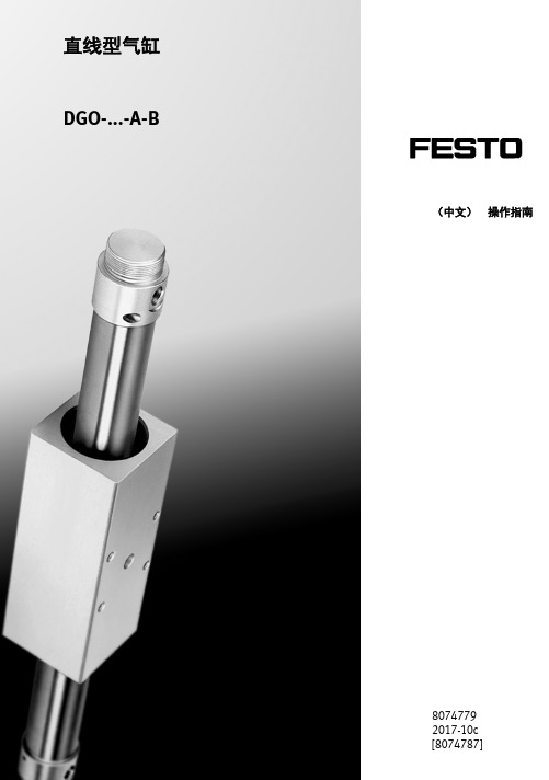
直线型气缸DGO-...-A-B(中文)操作指南80747792017-10c[8074787]DGO-...-A-BFesto DGO-...-A-B 2017-10c2原版操作手册的译本图符:安装与调试必须由具备相应资质的专业人员按照操作指南来实施。
警告注意环境附件中文–产品文件3............................................................DGO-...-A-BFesto DGO-...-A-B 2017-10c 中文3直线型气缸DGO-…-A-B 产品文件有关产品的所有可用文件 /pk1工作部件和接口1234561安装螺纹2气接口3用于固定工作负载的螺纹4注油嘴5内置开关磁铁6终端位置缓冲的调节螺丝(仅对于DGO-12-…)Fig.1DGO-...-A-BFesto DGO-...-A-B 2017-10c 中文42功能通过给气接口交替加压使内部的运动部件在气缸筒内往复运动。
磁性耦合装置将运动转换成外部运动部件。
3应用DGO-…设计用于进行负载传送。
4运输和存放•请注意此产品的重量。
根据规格,产品重量超过10kg 。
DGO-...-A-BFesto DGO-...-A-B 2017-10c 中文55产品使用前提条件注意使用不当可能造成功能故障。
•请确保始终遵守本章规定。
•请您将本操作指南中的极限值与实际使用情况下的极限值进行比较(例如:受力、扭矩、温度、质量)。
只有遵守负载极限值才能符合相关的安全规程安全运行本产品。
•请注意使用地点的环境条件。
环境中的腐蚀性元素会缩短产品的使用寿命(例如:臭氧)。
•请注意遵守同业公会、技术监督协会、VDE 的规定或相关国家规定。
•使用产品时请保持其原样,勿擅自进行任何改动。
•拆除包装材料,如薄膜、顶盖、纸板盒等。
例外:气接口上的不干胶防尘贴片(否则有污染危险)。
这些包装材料均为可回收材料(例外:油纸=废料)。
气动元件使用说明

气动元件使用说明一、气动元件的使用环境:一)无腐蚀性气体、无阳光直射、无有机溶剂、无化学药品、无明显粉尘、元爆炸性气体、无强磁的场合。
(二)环境温度一般在5℃~50℃之间。
(三)冲击和振动幅度应在气动元件的允许范围内。
(四)供电电压应在气动元件规定范畴内。
二、对使用气体的要求:(一)使用清洁干燥的压缩空气,根据不同的要求,采用相应的气源处理系统。
不得使用未经任何处理的压缩空气。
(二)在灰尘多、有水滴、油滴的场合应采取防护措施。
(三)冷凝水多、高温高湿的场合,在过滤器前应配置空气干燥器,后冷却器,自动排水器等。
三、气动元件的润滑:(一)为延长气动元件的使用寿命,除不供油润滑的元件外,一般应给油润滑。
给油时应选用流量合适的油雾器。
要用符合ISO VG32标准的专用润滑油(本公司供应此种润滑油)不得使用机油、锭子油等对气动密封件有害的润滑剂。
(二)润滑方法将油雾器的注油塞拧下,将专润滑油注入油杯内(亦可拧下油杯注油后再把油杯拧好),测量为油杯容积的80%左右为宜,同时调节滴油速度,使每1m3空气中含有0.5至5滴润滑油即可。
检查润滑是否良好,可以将一张清洁的白纸,放在换向阀的排气孔附近,阀工作三至四个循环后,若纸上只有很轻的斑点,表明润滑良好。
(三)对于不给油润滑的元件,一旦给油后,不得停止给油,否则会导致元件工作不良。
(四)更换气动元件的密封件时,在密封件上一定要涂抹规定的润滑油,否则会操作密封件。
四、常用气动元件应用及使用注意事项:<一>配管及管接头:1、应根据气动系统和气动元件对空气流量,安装方式的不同要求应用相应的配管和管接头。
2、配管前应吹净或洗净管内的油污、灰尘、金属屑,配管于管接头及气动元件连接时不允许将上述杂物及密封带的碎屑及粘接剂混入。
3、管接并没有安装时,请用六角扳手紧固,用力应适宜,否则会损坏元件、伤害人体或造成密封不良。
所以要求按下列数据接管。
4、用密封生料带缠绕时,留出1.5~2道丝扣,并按下图(图三)所示的方向缠绕。
Festo DGC式气体管道系统说明书
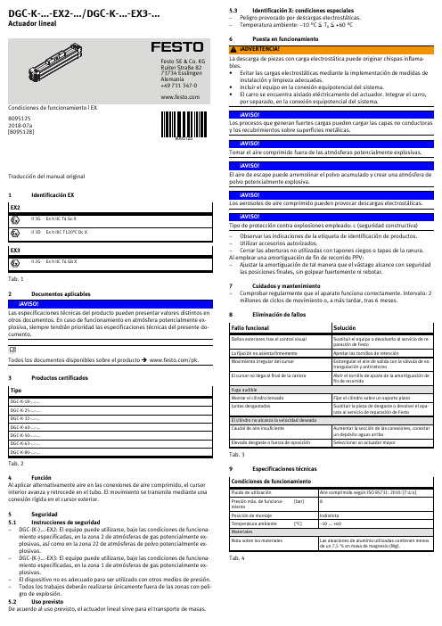
Traducción del manual original 1Identificación EXTab. 1 2Documentos aplicablesLas especificaciones técnicas del producto pueden presentar valores distintos en otros documentos. En caso de funcionamiento en atmósfera potencialmente explosiva, siempre tendrán prioridad las especificaciones técnicas del presente documento.Todos los documentos disponibles sobre el producto è /pk.3Productos certificadosTipoDGCK18......DGCK25......DGCK32......DGCK40......DGCK50......DGCK63......DGCK80......Tab. 24FunciónAl aplicar alternativamente aire en las conexiones de aire comprimido, el cursor interior avanza y retrocede en el tubo. El movimiento se transmite mediante una conexión rígida en el cursor exterior.5Seguridad 5.1Instrucciones de seguridad–DGC(K)...EX2: El equipo puede utilizarse, bajo las condiciones de funcionamiento especificadas, en la zona 2 de atmósferas de gas potencialmente explosivas, así como en la zona 22 de atmósferas de polvo potencialmente explosivas.–DGC(K)...EX3: El equipo puede utilizarse, bajo las condiciones de funcionamiento especificadas, en la zona 1 de atmósferas de gas potencialmente explosivas.–El dispositivo no es adecuado para ser utilizado con otros medios de presión.–Todos los trabajos deberán realizarse únicamente fuera de las zonas con peligro de explosión.5.2Uso previstoDe acuerdo al uso previsto, el actuador lineal sirve para el transporte de masas.5.3Identificación X: condiciones especiales –Peligro provocado por descargas electrostáticas.–Temperatura ambiente: –10 °C £ T a £+60 °C 6Puesta en funcionamientoLa descarga de piezas con carga electrostática puede originar chispas inflamables.•Evitar las cargas electrostáticas mediante la implementación de medidas deinstalación y limpieza adecuadas.•Incluir el equipo en la conexión equipotencial del sistema.•El carro se encuentra aislado eléctricamente del actuador. Integrar el carro,por separado, en la conexión equipotencial del sistema.Los procesos que generan fuertes cargas pueden cargar las capas no conductoras y los recubrimientos sobre superficies metálicas.Tomar el aire comprimido fuera de las atmósferas potencialmente explosivas. El aire de escape puede arremolinar el polvo acumulado y crear una atmósfera de polvo potencialmente explosiva.Los aerosoles de aire comprimido pueden provocar descargas electrostáticas.Tipo de protección contra explosiones empleado: c (seguridad constructiva)–Observar las indicaciones de la etiqueta de identificación de productos.–Utilizar accesorios autorizados.–Cerrar las aberturas no utilizadas con tapones ciegos o tapas de la ranura.Al emplear una amortiguación de fin de recorrido PPV:–Ajustar la amortiguación de tal manera que el vástago alcance con seguridadlas posiciones finales, sin golpear fuertemente ni rebotar.7Cuidados y mantenimiento–Comprobar regularmente que el aparato funciona correctamente. Intervalo: 2millones de ciclos de movimiento o, a más tardar, tras 6 meses.8Eliminación de fallosTab. 3 9Especificaciones técnicasTab. 48095125DGC-K-...-EX2-.../DGC-K-...-EX3-...Actuador lineal8095125201807a [8095128]Festo SE & Co. KG Ruiter Straße 82 73734 Esslingen Alemania+49 711 347。
Festo VADM-70-N 高压型高效空气泵说明书
09/11/2023 – Sujeito a alterações – Festo SE & Co. KG
1/2
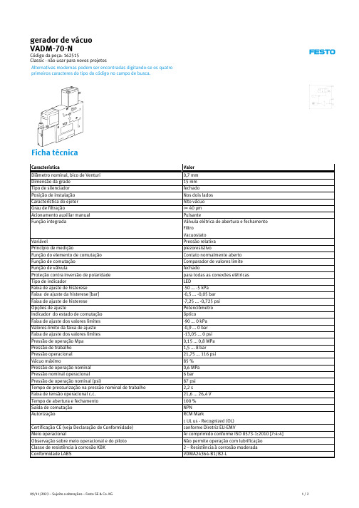
Característica Temperatura do meio Classe de proteção Temperatura ambiente Peso do produto Faixa de medição de pressão
Ficha técnica
Característica Diâmetro nominal, bico de Venturi Dimensão da grade Tipo de silenciador Posição de instalação Característica do ejetor Grau de filtração Acionamento auxiliar manual Função integrada
Conexão elétrica
Tipo de fixação
Conexão pneumática 1 Conexão pneumática 3 Conexão de vácuo Observações sobre material Material das vedações Material do bico de coleta Material do filtro Material da corpo do filtro Material do corpo Material do silenciador
gerador de vácuo VADM-70-N
Código da peça: 162515 Classic - não usar para novos projetos
Alternativas modernas podem ser encontradas digitando-se os quatro primeiros caracteres do tipo do código no campo de busca.
油压冲床设备操作说明书
核准
审核
制作
日期
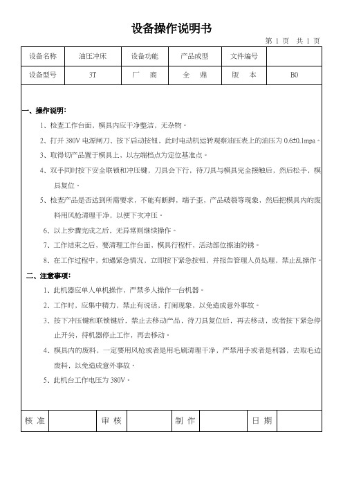
5﹑检查产品是否达到所需要求﹐不能有断脚﹐端子歪﹐产品破裂等现象﹐然后把模具内的废料用风枪清理干净﹐以便下次冲压。
6﹑以上步骤完成之后﹐无异常则继续操作。
7﹑工作结束之后﹐要清理工作台面﹐模具行程杆﹐活动部位擦油防锈。
8﹑在工作过程中﹐如遇紧急情况﹐立即按下紧急按钮﹐并报告管理人员处理﹐禁止乱操作。
二﹑注器。
2﹑工作时﹐应集中精力﹐禁止有说话﹐打闹现象﹐以免造成意外事故。
3﹑按下冲压键和联锁键后﹐禁止去移动产品﹐待刀具复位后﹐再去移动﹐或者按下紧急停止开关﹐待机器停止工作﹐再去移动。
4﹑模具内的废料﹐一定要用风枪或者是用毛刷清理干净﹐严禁用手或者是利器﹐去取毛边废料﹐以免造成意外事故。
设备操作说明书
第1页共1页
设备名称
油压冲床
设备功能
产品成型
文件编号
设备型号
3T
厂商
全鼎
版本
B0
一﹑操作说明﹕
1﹑检查工作台面﹐模具内应干净整洁﹐无杂物。
2﹑打开380V电源闸刀﹑按下启动按钮﹐此时电动机运转观察油压表上的油压为0.6±0.1mpa。
3﹑取得切产品置于模具上﹐以左端档点为定位基准点。
4﹑双手同时按下安全联锁和冲压键﹐刀具会下行﹐待刀具与模具完全接触后﹐然后松手﹐模具复位。
亚德客 AVPVSL 气动薄膜阀 - 技术手册说明书
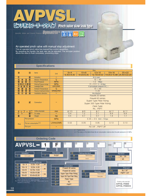
10
Body material 17%'
ᶄ ̢ *
Tubing standard Millimeter Inch
ᶇ OB
Revision ˘ɺ˘
˘
̨ ̛ ˞ ̧˞ ̣˞
Connection 'MPXFMMTFSJFT 'MPXFMMTFSJFT 4VQFS5ZQF1JMMBS'JUUJOH 4VQFS5ZQF1JMMBS'JUUJOH
'MBSF5ZQF 3D
Unit
ʵ ˆ .1B .1B DNNJO ˆ UJNFTNJO ʵ
ଓ Connection
ʵ
Φ Ϧ ϑ Ο ε˞ Orifice diameter
$ W ɹ ˞ Cv value
ॏ
ྔ Weight
Pilot pressure
Pilot
Pilot air consumption※2
Pilot port
'MBSF5ZQF
JODI
3Dɺ'/15
JODI
#
˘
˘
˘
˘
˘
$
."9
."9
."9
."9
."9
AVPVSL
- 1、下载文档前请自行甄别文档内容的完整性,平台不提供额外的编辑、内容补充、找答案等附加服务。
- 2、"仅部分预览"的文档,不可在线预览部分如存在完整性等问题,可反馈申请退款(可完整预览的文档不适用该条件!)。
- 3、如文档侵犯您的权益,请联系客服反馈,我们会尽快为您处理(人工客服工作时间:9:00-18:30)。
亚德客DMSG说明书
电磁阀选型首先应该依次遵循安全性,可靠性,适用性,经济性四大原则,其次是根据六个方面的现场工况(即管道参数、流体参数、压力参数、电气参数、动作方式、特殊要求进行选择)。
选型依据:
一、根据管道参数选择电磁阀的:通径规格(即)、接口方式、按照现场管道内径尺寸或流量要求来确定通径0尺寸。
接口方式,一般>要选择法兰接口,s则可根据用户需要自由选择。
二、根据流体参数选择电磁阀的:材质、温度组、腐蚀性流体:宜选用耐腐蚀电磁阀和全不锈钢;食用超净流体:宜选用食品级不锈钢材质电磁阀。
高温流体:要选择采用耐高温的电工材料和密封材料制造的电磁阀,而且要选择活塞式结构类型的。
流体状态:大至有气态,液态或混合状态,特别是口径大于订货时一定要区分开来。
流体粘度:通常在以下可任意选择,若超过此值,则要选用高粘度电磁阀。
三、根据压力参数选择电磁阀的:原理和结构品种、公称压力:这个参数与其它通用阀门的含义是一样的,是根据管道公称压力来定。
工作压力:如果工作压力低则必须选用直动或分步直动式原理;最低工作压差在以上时直动式、分步直动式、先导式均可选用。
四、电气选择:电压规格应尽量优先选用、较为方便。
五、根据持续工作时间长短来选择:常闭、常开、或可持续通
电当电磁阀需要长时间开启,并且持续的时间多余关闭的时间应选用常开型。
要是开启的时间短或开和关的时间不多时,则选常闭型。
但是有些用于安全保护的工况,如炉、窑火焰监测,则不能选常开的,应选可长期通电型。