VPAPIII简明操作指南
VRP3.3 操作手册 03_接口
目录第1章接口配置概述..............................................................................................................1-11.1 接口介绍.............................................................................................................................1-11.2 接口的配置.........................................................................................................................1-11.2.1 接口的视图..............................................................................................................1-11.2.2 设置接口描述...........................................................................................................1-21.2.3 配置接口平均速率统计周期.....................................................................................1-21.2.4 进一步配置接口的方法............................................................................................1-21.3 接口的显示和调试..............................................................................................................1-3第2章 LAN接口配置..............................................................................................................2-12.1 以太网接口.........................................................................................................................2-12.1.1 以太网接口介绍.......................................................................................................2-12.1.2 以太网接口的配置....................................................................................................2-12.1.3 设置太网接口的流控方式.........................................................................................2-52.1.4 以太网接口的显示和调试.........................................................................................2-52.1.5 以太网接口典型配置举例.........................................................................................2-52.1.6 以太网接口常见故障的诊断与排除..........................................................................2-6第3章 WAN接口配置............................................................................................................3-13.1 异步串口.............................................................................................................................3-13.1.1 异步串口介绍...........................................................................................................3-13.1.2 异步串口的配置.......................................................................................................3-13.2 AUX接口............................................................................................................................3-53.2.1 AUX接口介绍..........................................................................................................3-53.2.2 AUX接口配置..........................................................................................................3-53.3 同步串口.............................................................................................................................3-73.3.1 同步串口介绍...........................................................................................................3-73.3.2 同步串口的配置.......................................................................................................3-73.4 AM接口............................................................................................................................3-133.4.1 AM接口介绍..........................................................................................................3-133.4.2 AM接口的配置......................................................................................................3-133.5 ISDN BRI接口.................................................................................................................3-143.5.1 ISDN BRI接口介绍...............................................................................................3-143.5.2 ISDN BRI接口的配置............................................................................................3-153.6 CE1/PRI接口...................................................................................................................3-163.6.1 CE1/PRI接口介绍.................................................................................................3-163.6.2 CE1/PRI接口的配置.............................................................................................3-163.6.3 CE1/PRI接口的显示和调试...................................................................................3-213.7 CT1/PRI接口...................................................................................................................3-213.7.1 CT1/PRI接口介绍.................................................................................................3-213.7.2 CT1/PRI接口的配置..............................................................................................3-223.7.3 CT1/PRI接口的显示和调试...................................................................................3-263.8 E1-F接口.........................................................................................................................3-263.8.1 E1-F接口介绍.......................................................................................................3-263.8.2 E1-F接口的配置....................................................................................................3-273.8.3 E1-F接口的显示和调试.........................................................................................3-303.9 T1-F接口.........................................................................................................................3-303.9.1 T1-F接口介绍........................................................................................................3-303.9.2 T1-F接口的配置....................................................................................................3-313.9.3 T1-F接口的显示和调试.........................................................................................3-343.10 CE3接口........................................................................................................................3-343.10.1 CE3接口介绍......................................................................................................3-343.10.2 CE3接口的配置...................................................................................................3-343.10.3 CE3接口的显示和调试........................................................................................3-373.11 CT3接口........................................................................................................................3-383.11.1 CT3接口介绍......................................................................................................3-383.11.2 CT3接口的配置...................................................................................................3-393.11.3 CT3接口的显示和调试........................................................................................3-43第4章 ATM/DSL接口配置.....................................................................................................4-14.1 ATM/DSL接口介绍............................................................................................................4-14.2 ATM E3/T3接口配置.........................................................................................................4-14.2.1 进入指定ATM E3/T3的接口视图............................................................................4-24.2.2 配置ATM E3/T3接口的时钟模式............................................................................4-24.2.3 配置ATM T3接口的电缆模式.................................................................................4-24.2.4 配置ATM E3/T3接口的帧格式...............................................................................4-34.2.5 配置ATM E3/T3接口的加扰功能............................................................................4-34.2.6 配置ATM E3/T3接口的环回方式............................................................................4-44.3 ATM 25M 接口...................................................................................................................4-44.3.1 ATM 25M接口配置..................................................................................................4-44.4 ATM OC-3c/STM-1接口....................................................................................................4-64.4.1 ATM OC-3c/STM-1接口配置..................................................................................4-64.5 ADSL接口..........................................................................................................................4-84.5.1 ADSL接口配置........................................................................................................4-94.6 G.SHDSL接口.................................................................................................................4-114.6.1 G.SHDSL接口配置...............................................................................................4-114.7 ATM和DSL接口的显示和调试.......................................................................................4-144.8 ATM和DSL接口故障的诊断与排除................................................................................4-154.8.1 ATM OC-3c/STM-1接口.......................................................................................4-154.8.2 DSL接口故障的诊断与排除..................................................................................4-15第5章逻辑接口配置..............................................................................................................5-15.1 Dialer接口..........................................................................................................................5-15.1.1 Dialer接口介绍........................................................................................................5-15.2 Loopback接口...................................................................................................................5-15.2.1 Loopback接口介绍.................................................................................................5-15.2.2 Loopback接口的配置..............................................................................................5-15.3 Null接口.............................................................................................................................5-25.3.1 Null接口介绍...........................................................................................................5-25.3.2 Null接口的配置.......................................................................................................5-25.4 子接口................................................................................................................................5-35.4.1 子接口介绍..............................................................................................................5-35.4.2 子接口的配置...........................................................................................................5-35.5 备份中心逻辑通道..............................................................................................................5-65.5.1 备份中心逻辑通道介绍............................................................................................5-65.5.2 备份中心逻辑通道的配置.........................................................................................5-65.6 虚拟接口模板和虚拟接口...................................................................................................5-75.6.1 虚拟接口模板和虚拟接口介绍.................................................................................5-75.6.2 虚拟接口模板的配置................................................................................................5-75.6.3 虚拟接口模板和虚拟接口的显示和调试...................................................................5-85.6.4 虚拟接口模板常见故障的诊断与排除.......................................................................5-85.7 虚拟以太网接口..................................................................................................................5-95.7.1 虚拟以太网接口介绍................................................................................................5-95.7.2 虚拟以太网接口配置................................................................................................5-9第1章接口配置概述1.1 接口介绍路由器的接口即指路由器系统与网络中的其它设备交换数据并相互作用的部分,其功能就是完成路由器与其它网络设备的数据交换。
VPAP III ST中文

19
持续而且有针对性地漏气补偿
1
3
20
5 4
1 触发点 2 漏气 3 自动漏气补偿 4 提升后的新的基础压力基线 5 经过漏气补偿后的触发点
3
4
T模式:时间控制模式
• 在此模式下,医生设定呼吸频率及吸气时间。当需要固定 的呼吸时间和呼吸频率,病人又不能持续触发呼吸机或基 础呼吸频率较低时,采用此种模式。需要注意的是,时间 模式是一种控制模式,不依赖于病人的呼吸动度,即便这 种动度存在。
• 当需要固定的吸气时间和呼吸频率的患者
5
6
S模式:自动触发模式
• 瑞思迈VPAP III系列双水平无创呼吸机内存储着瑞思迈梦幻系列 各款面罩在各种压力水平下的正常排气量数据库,通过实时监测 患者的呼吸气流,Vsync程序可准确识别正常排气及漏气自动调 整基准气流阈值,实现漏气补偿。准确判定何时触发、何时转换
• 若气流超过基准阈值,则触发一次IPAP;气流低于基准阈值,则 转换到EPAP。这样VPAP就能在不同的漏气情况下保证人机同步
11
•1. RESMED 瑞思迈世界领先水平的面罩
瑞思迈全新梦幻口鼻面罩,采用人体工学设计,可有效防止面 罩本身及因张口呼吸而导致的漏气,提高CO2排放率,从而改善各类 通气治疗的疗效,可全面应用于各类无创通气 治疗设备
12
选择正确舒适有效的面罩
治疗成败的重要条件
• 是否使用了适合患者的面罩 • 是否考虑到了患者的舒适性 • 面罩的漏气及安全性
小于某值时呼吸机压力 转换为 EPAP
ResMED VPAP III呼吸机功能键和临床菜单
VPAP III简易操作指南
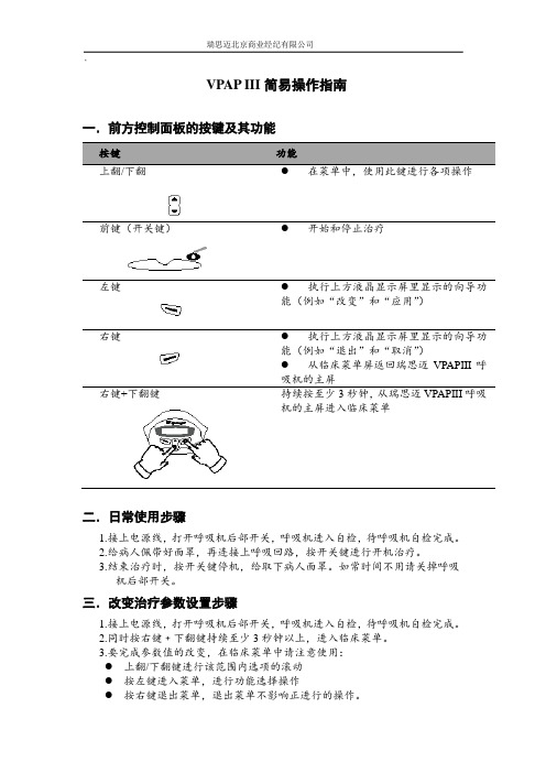
一.前方控制面板的按键及其功能
按键功能
上翻/下翻●在菜单中,使用此键进行各项操作前键(开关键)●开始和停止治疗
左键●执行上方液晶显示屏里显示的向导功
能(例如“改变”和“应用”)右键●执行上方液晶显示屏里显示的向导功
能(例如“退出”和“取消”)
●从临床菜单屏返回瑞思迈VPAPIII呼
吸机的主屏
右键+下翻键持续按至少3秒钟,从瑞思迈VPAPIII呼吸
机的主屏进入临床菜单
二.日常使用步骤
1.接上电源线,打开呼吸机后部开关,呼吸机进入自检,待呼吸机自检完成。
2.给病人佩带好面罩,再连接上呼吸回路,按开关键进行开机治疗。
3.结束治疗时,按开关键停机,给取下病人面罩。
如常时间不用请关掉呼吸
机后部开关。
三.改变治疗参数设置步骤
1.接上电源线,打开呼吸机后部开关,呼吸机进入自检,待呼吸机自检完成。
2.同时按右键﹢下翻键持续至少3秒钟以上,进入临床菜单。
3.要完成参数值的改变,在临床菜单中请注意使用:
●上翻/下翻键进行该范围内选项的滚动
●按左键进入菜单,进行功能选择操作
●按右键退出菜单,退出菜单不影响正进行的操作。
VPAP III 临床菜单
红色为出院时参数
16)。
CPAP可选8
4.6)
ON)
则每隔6秒(60/10),
(300ms)
2S)
(0.1s)
med)
呼气灵敏度(high)
面罩报警(off)
自动显示。
ResMedVPAP

具有QuickNav(快速导航)功能的VPAP™III ST-A呼吸机使用者指南简体中文简体中文前言 . . . . . . . . . . . . . . . . . . . . . . . . . . . . . . . . . . . . . . . . . . . . . . . . . . . . . . 1使用者/拥有者的责任 1医疗信息 . . . . . . . . . . . . . . . . . . . . . . . . . . . . . . . . . . . . . . . . . . . . . . . . . . 1设计用途 1禁用范围 1副作用 1具有QuickNav(快速导航)功能的VPAP III ST-A呼吸机 . . . . . . 2面罩 2湿化器 2设置装置 . . . . . . . . . . . . . . . . . . . . . . . . . . . . . . . . . . . . . . . . . . . . . . . . . . 2连接湿化器 3使用LCD(液晶显示)QuickNav屏幕和小键盘 4开始治疗 . . . . . . . . . . . . . . . . . . . . . . . . . . . . . . . . . . . . . . . . . . . . . . . . . . 5患者待用屏幕 6使用面罩试戴功能 6停止治疗 7如何使用菜单 . . . . . . . . . . . . . . . . . . . . . . . . . . . . . . . . . . . . . . . . . . . . . . 7 QuickNav屏幕 7菜单导航 7患者治疗菜单 8患者小结菜单 8患者设置菜单 8患者选项菜单 9警报 . . . . . . . . . . . . . . . . . . . . . . . . . . . . . . . . . . . . . . . . . . . . . . . . . . . . . 10排除警报 10清洁和维护 . . . . . . . . . . . . . . . . . . . . . . . . . . . . . . . . . . . . . . . . . . . . . . . 12维修 13有用提示 . . . . . . . . . . . . . . . . . . . . . . . . . . . . . . . . . . . . . . . . . . . . . . . . . 13排除故障 . . . . . . . . . . . . . . . . . . . . . . . . . . . . . . . . . . . . . . . . . . . . . . . . . 14系统规格 . . . . . . . . . . . . . . . . . . . . . . . . . . . . . . . . . . . . . . . . . . . . . . . . . 15一般性警告和注意事项 17指南和制造商声明 – 电磁辐射和抗干扰性 18有限保证 . . . . . . . . . . . . . . . . . . . . . . . . . . . . . . . . . . . . . . . . . . . . . . . . . 20简体中文具有QuickNav ™(快速导航)功能的VPAP ™ III ST-A 呼吸机是一种双水平压力支持性呼吸机,专为无创性面罩通气而设计。
Raspberry Pi 3 快速入门指南说明书

Raspberry Pi Quick-Start GuideRev 1.0, Apr 2017Table of Contents1.Raspberry Pi Start Kits (2)A.Generation Introduction: (2)B. Parking list: (2)2.Assembly (3)A.16GB Micro SD Pre-Loaded with Raspbian (3)B. Power Supply Adapter Charger 5V 2.5A (US) (4)B cable with ON/OFF switch (5)C.ABS Protective Case (6)D.Heatsink kit with Thermal Pad (7)3.Installation diagram (8)A.Getting started (10)B.Raspbian System (11)C.Guide to connecting WIFI (16)1.Raspberry Pi Start KitsA.Generation Introduction:The Raspberry Pi 3 Starter Kit is a great way to gain a solid introduction to the small, credit-card sized computer. The starter kit makes the Raspberry Pi intuitive and easy to learn.With this kit, you will be able to get your Raspberry Pi 3 as your own credit card sized computer, getting started with programming and coding. So, if you are looking for a new challenge or a way to get in on the RPi craze, check out the Raspberry Pi 3 Starter Kit! UCTRONICS team has carefully done the compatibility test for all components, and offer the plug and play boot operation system like Raspbian. Users only need additional HDMI monitor and keyboard/mice to use this kit as a standard PC desktop.B. Parking list:➢1pcs 16GB Micro SD Pre-Loaded with Raspbian➢1pcs Power Supply Adapter Charger 5V 2.5A (US)➢1pcs USB cable with ON/OFF switch➢1pcs ABS Protective Case➢3pcs Heatsink kit with Thermal Pad2.AssemblyA.16GB Micro SD Pre-Loaded with RaspbianThis Micro SD Card Bundle for the Raspberry Pi consists of a SanDisk Class 10 Micro SD card pre-loaded with the Official Raspberry Pi Raspbian.Specification:➢Capacity: 16GB➢Weight: 0.2g➢Simply plug this SD card into your Raspberry Pi➢Fully tested to work with the Raspberry Pi 3 Model B➢Pre-Loaded with pre-loaded with the Raspberry Pi Raspbian imageB. Power Supply Adapter Charger 5V 2.5A (US)These have a standard USB ‘A’ connector for the output so you can power your Arduino, Raspberry Pi, etc. through a USB cable. Any device that uses a USB cable for charging or power can be powered with this supply.Specification:➢Input Voltage: AC100-240V 50/60Hz➢Output: DC 5.0v 2500mA (2.5A)➢Adapter plug type: US➢Overload Protection➢Consistent fixed switching voltageB cable with ON/OFF switchThis Raspberry Pi Micro USB Cable with ON / OFF Switch is specifically designed for Raspberry Pi. Just press the button to turn your Pi on or off, no need to pull the cable to restart or reboot your Raspberry Pi which prevents the Raspberry Pi's Micro USB connector from frequent pulling and inserting the USB cable. 1.5m length can be used as power supply for the Raspberry Pi module, not for data transfer use.Specification:➢Type: On/Off switch➢Length: 1.5m Long➢Color: Black➢Connector Type A: USB➢Connector Type B: Micro USBC.ABS Protective CaseIt has slim openings for all your cables, an easy-to-remove beveled slot for your Micro SD card, slots for both your Pi Camera and upcoming Display, and a space for your GPIO cable to extend out from the Pi. Two-piece injection- ABS Case that snaps together which is easy to stall.Specification:➢Material: ABS plastic case➢Dimensions: External:96 x 66 x 41mm➢Color: black➢With 4 screws and 4 non-slip matsD.Heatsink kit with Thermal PadThe Raspberry Pi Heat Sink Kit consists of three high quality aluminum heat sinks, each selected to match the size of the main heat out-put components on the Raspberry Pi board. The heatsinks are designed to fit on top of the Broadcom and Ethernet SOC's which will Extend the life of your Raspberry Pi and reduce the risk of hardware failure.Specification:➢Number: 3 pcs Silver Aluminum Heat Sinks➢Thermal Resistance: 25°C/W.➢Dimension: 9x9x5mm14x14x6mm➢Floor Thinness: 1.6mm, 1.1mm➢Vane Thickness: 0.8mm, 0.6mm3.Installation diagramFigure1.Caution: The internal Wi-Fi antenna is fragile, be careful and please don't press with too much strength when installing.Figure2Figure3Figure4.A.Getting started1. If you have a case, start by installing the Raspberry pi inside the case.2. Insert a pre-programmed MicroSD card into the MicroSD card slot on the bottom side of the Raspberry Pi.3. Connect a USB keyboard and mouse to the USB ports.4. Connect a HDMI monitor or TV to the Raspberry Pi using a HDMI cable. Ensure your monitor or TV is turned on and that you have selected the correct input.5. Once all connections have been made, it is now time to connect the MicroUSB Power Supply to the board. When the power is connected, the Raspberry Pi will start to boot.B.Raspbian SystemRaspbian is the Foundation’s official supported operating system. Raspbian comes pre-installed with plenty of software for education, programming and general use. It has Python, Scratch, Sonic Pi, Java, Mathematica and more.Raspbian desktop overiewProgramming menuInternet menuAccessories menuPreferences menuShutdown... menuC.Guide to connecting WIFIIf you want to connect your Raspberry Pi to the internet or local network then you will need to follow these steps:1.WiFi connections can be made via the network icon at the right-hand end of the menubar. left-clicking this icon will bring up a list of available WiFi networks.2.If no networks are found, it will show the message "No APs found - scanning...": just waita few seconds without closing the menu, and it should find your network.3.The icons on the right show whether a network is secured or not, and its signal strength.Click the network that you want to connect to. If it's secured, a dialogue box will appear prompting you to enter the network key.4.Enter the key and press OK, then wait a couple of seconds. The network icon will flashbriefly to show that a connection is being made. Once it's ready, the icon stops flashing and shows the signal strength.。
Presys Plus Onboard Preamplifier 3 用户手册说明书

USER GUIDEPRESYS PLUS ONBOARD PREAMPPresys Plus Quick Start1. Set the controls • Set volume and notch off. Set the bass, middle, treble and brilliance controls to center.2. Plug in • Connect the Presys Plus to an amplifi er or PA with a ¼-inch instrument cable. The battery light (batt) will fl ash once quickly to indicate it has switched on.3. T urn up • Raise the volume and adjust the bass, middle, treble and brilliancecontrols to your liking.23Presys Plus ControlsVolume • For the cleanest signal, set the volume knob as high as possible, without causing distortion or feedback.Bass • Boost here to add depth and weight to the sound of the guitar.Middle • Turn the middle knob all the way left for a smooth “scooped out” tone at high volume levels. Raise the middle knob to the right of center to add midrange “bite” to the sound.T reble • Boost to cut through the mix. Cut to mellow and subdue the sound. Brilliance • This slider can add shimmer and sparkle to your sound. It zeros in on crisp high frequency tones, the realm of harmonics and acoustic string sound. Lower the brilliance slider to reduce fi nger noise and fret buzz.Notch • Tune the notch fi lter to remove low-end feedback. Raise the volume until feedback occurs, then slowly turn the notch to the right until the feedback is eliminated.Phase • Use the phase switch to improve bass response at low volume and suppress feedback at high volume.T uner • Use the tuner lights as shown below to tune your instrument.Battery • When the batt indicator lights steadily it is time to change the bat-tery. To conserve power, unplug the instrument and turn off the tuner when not in use. Replace the battery by fl ipping open the preamp body using the latch located above the Fishman logo. Be sure to observe the correct polarity duringthis installation.“A” notebelow pitch“A” notein tune“A” noteabove pitch“A#” notein tune45Sample EQ SettingsFingerstyle“Scooped”MidThis will add fullness to the bass This setting emphasizes extreme bass and defi nition to the treble. and treble Strummer Cut Through the MixA good setting for strumming chords. When you need to be heard through aloudband.67FCC COMPLIANCE NOTICEThis equipment has been tested and found to comply with the limits for a Class B digital device,pursuant to Part 15 of the FCC rules. These limits are designed to provide reasonable protectionagainst harmful interference in a residential installation. This equipment generates, uses and canradiate radio frequency energy and if not used in accordance with the instructions, may cause harmful interference to radio communications and there is no guarantee that interference will not occur in a particular installation. If this equipment does cause harmful interference to radio or television recep-tion, which can be determined by turning the equipment off and on, the user is encouraged to try to correct the interference by one or more of the following measures: reorient or relocate the receiving antenna, increase the separation between the equipment and receiver, connect the equipment intoan outlet on a circuit different from that of the receiver. Consult the dealer or an experienced radio/TV technician if help is needed with interference.NOTE: FMIC and Fishman Transducers, Inc. are not responsible for unauthorized equipmentmodifi cations that could violate FCC rules, and/ or void product safety certifi cations.www.fi 513-300-184 Rev C 2-11。
PiPO品铂S3说明书
S3 平板电脑—S3使用手册S3您 好!感谢您购买本公司平板电脑。
为了使您尽快轻松自如地操作您的产品,我们随机配备了内容详尽的用户手册,您可以获取有关产品介绍、使用方法等方面的知识。
使用您的产品之前,请仔细阅读我们随机提供的所有资料,以便您能更好地使用该产品。
请随时备份您的数据资料到您的电脑上。
本公司对于因软件、硬件的误操作、产品维修、电池更换或其它意外情况所引起的个人数据的丢失和损坏不负任何责任,也不对由此而造成的其它间接损失负责。
同时我们无法控制用户对本手册可能造成的误解,因此,本公司将不对在使用本手册过程中可能出现的意外损失负责,并不对因使用该产品而引起的第三方索赔负责。
本手册信息受到版权保护,其任何部分未经本公司事先书面许可,不准以任何方式影印和复制。
本公司保留对本手册、三包凭证及其相关资料的最终解释权。
本产品符合GB/T 18220-2000手持式个人信息处理设备通用规范。
S3注意事项² 不要在高度潮湿的环境下使用适配器,切勿用湿的手足去碰适配器。
² 切勿用金属物体接触机器,这样容易造成机器短路。
² 请不要试图分解或改造本机,这样可能导致电击或妨碍产品质保。
² 清洁机器时,请使用柔软的布清洁表面。
请注意不要让液体进入机器内部。
² 禁止儿童单独玩耍本机,请勿摔落或与硬物摩擦撞击,否则可能导致机器表面磨花、硬盘损伤、数据丢失或其它硬件损坏。
² 本机被作为移动硬盘使用时,请按正确文件管理操作方法存储导出文件,任何操作导致的文件丢失,本公司概不负责。
建议及时备份存放在本机中的个人资料。
² 禁止本品使用超负荷电源、用力弯曲或用重物挤压电源线,以免引起发热造成火灾。
² 因为本产品的性能和功能而发生的变更,可能会不做另行通知,请您谅解。
² 若因固件程序升级而导致本产品的实际设置和使用方法等与本手册不一致,请访问本公司官方网站或拨打服务热线400-716-1515查询最新信息。
EPSON 用户指南(Perfection V33 和 Perfection V330 )
回到顶部
指示灯和按键
按钮
使用扫描仪按钮之前,确保您已安装Epson Scan和Epson Event Manager。
按钮
电源/ 钮
启动按
电源
复印 E-mail PDF
参见使用扫描仪按钮。
启动
功能 如果按下一次可打开扫描仪电源。 当扫描仪电源打开时,按下此按钮3秒钟可关闭扫描仪。 (当扫描 软件正在运行时,您不能关闭扫描仪。) Epson Scan启动。
注释: 有关详细信息请参见Epson Scan帮助。 如果清除下一次扫描前显示此对话框复选框,Epson Scan立即启动扫描无需显示此屏幕。 要返回到此屏幕,在扫描时单击扫描对话框中的取消。
对于胶片或幻灯片注释说明: 在全自动模式下,仅可以扫描35毫米的彩色胶片或彩色正片幻灯片。 要扫描其他类型的胶片,使 用家庭模式或专业模式。 要更改扫描模式,请参见选择Epson Scan模式。
进行图像类型设置。 进行文稿来源设置。 选择原始文稿的尺寸作为尺寸设置。 为您的原稿选择一个合适的分辨率作为分辨率设置。 单击预览可预览您的图像。 预览窗口出现并显示图像。 有关详细信息,请参见预览和调整扫描区域。 按需要指定图像质量。 有关详细信息,请参见调整颜色和其它图像设置。 单击扫描。 您扫描的图像在文件保存设置窗口中按您选择的文件格式和位置保存。 如果您没有在文件保存设置窗口中选 择任何设置,它将以JPEG文件保存在Pictures或My Pictures文件夹中。
ArcSoft Scan-n-Stitch Deluxe (仅Windows): 从选择扫描仪中选择您的扫描仪, 然后单击扫描页。
Presto! PageManager: 打开文件菜单,选择选择来源,然后选择您的扫描仪。
VPAPIII简明操作指南

VPAPIII 简明操作指南
一.前方控制面板的按键及其功能
按键
功能 上翻/下翻
●
在菜单中,使用此键进行各项操作
前键(开关键)
●
开始和停止治疗
左键
● 执行上方液晶显示屏里显示的向导功能(例如“改变”和“应用”) 右键
● 执行上方液晶显示屏里显示的向导功能(例如“退出”和“取消”)
● 从临床菜单屏返回瑞思迈VPAPIII 呼吸机的主屏
右键+下翻键
持续按至少3秒钟,从瑞思迈VPAPIII 呼吸机的主屏进入临床菜单
二.日常使用步骤
1.接上电源线,打开呼吸机后部开关,呼吸机进入自检,待呼吸机自检完成。
2.给病人佩带好面罩,再连接上呼吸回路,按开关键进行开机治疗。
3.结束治疗时,按开关键停机,给取下病人面罩。
如常时间不用请关掉呼吸机后部开
关。
三.改变治疗参数设置步骤
1.接上电源线,打开呼吸机后部开关,呼吸机进入自检,待呼吸机自检完成。
2.同时按右键﹢下翻键持续至少3秒钟以上,进入临床菜单。
3.要完成参数值的改变,在临床菜单中请注意使用:
● 上翻/下翻键进行该范围内选项的滚动 ● 按左键进入菜单,进行功能选择操作
● 按右键退出菜单,退出菜单不影响正进行的操作。
临床菜单详见第二页
VPAP III 临床设置菜单
模式选择
吸气压
呼气压
呼吸频率
呼吸转换时间
最大吸气压时间
最小吸气压时间
面罩漏气报警
自动开关机
面罩类型
湿化器类型
管路长度
最大延迟时间
开始压力。
VPAPIIIST-A详细操作培训

•湿化调节旋钮
•水罐开启卡扣 •水罐抽出
•送气端口
Quattro口鼻面罩
•头带 •额头支撑
•头带卡扣 •旋转接头
•调节旋钮 •双层硅胶垫 •硅胶垫卡扣 •防窒息呼气阀
VPAP III ST-A附件的连接
VPAP III ST-A开机程序
连接好随机附件后按如下程序开机: 1、连接电源线 2、打开机器后部的电源开关 3、解除面板锁定,进入临床设定菜单 4、修改或调节通气参数 5、患者佩戴面罩,开始进行通气治疗。
• 通过快速查看(QuickView)按钮 治疗的影响.
来查看设置的改变对临床
• 数据查看项-介绍
数据查看- 使用效果数据
➢每天 ➢每周 ➢每月 ➢6 个月 ➢壹年
数据查看 – 使用时间数据
➢每天 ➢每周 ➢每月 ➢6 个月 ➢壹年
数据界面 – 历史事件
➢Day 1 ➢Day 2 ➢Day 3 ➢Day 4 ➢Day 5
• To meet the new standards the new alarm volumes are - Low 72dB, Med 80dB, High 84dB (min 2dB louder than the ST-A)
• Press Enter to view alarms from Day 1 to Day 5 • Alarms are recorded in 24 hour sessions from 12pm to 12pm
• 临床菜单结构-介绍
临床菜单结构
治疗监测
•治疗监测:共有3页实时治疗监测数据及 Ti吸气触发窗
•数据查看:可查看数据包括: 使用效果数据, 临床使用数据, •报警历史, 事件历史, 设定数值及服务提醒
VPAN 3代说明书

VPAN 3代快速设置1.VPAN开关机VPAN关机状态时,长按VPAN机身中央圆形的开关机键2s左右,VPAN开机。
VPAN工作状态时,长按VPAN机身中央圆形的开关机键5s左右,VPAN关机。
VPAN休眠状态时,短按VPAN机身中央圆形的开关机键,可解决VPAN休眠状态。
2.下载安装“VPAN”APP手机扫描说明书上的二维码,关注“四维空间”微信公众号,点击菜单下载安装“VPAN”APP或在App Store(苹果)、各大安卓市场搜索“VPAN”APP下载安装。
3.手机连接VPAN点击手机“设置——Wi-Fi(无线网络)”,连接VPAN WiFi信号。
4.VPAN 外网设置手机成功连接VPAN WiFi信号后,在“VPAN”APP中,点击“我——外网设置”,选择外网连接。
5.VPAN迅雷设置VPAN成功连上外网后,在“VPAN”APP中,点击“我——迅雷设置”,点击“手动配置”(登陆自己的迅雷账号)或“自动配置”(推荐),登陆成功后,返回“我”的页面,点击“迅雷设置”,点击“手动绑定”或“自动绑定”(推荐)。
操作步骤1.长按VPAN机身中央圆形的开关机键2s左右,VPAN开机。
2.手机扫描说明书上的二维码,关注“四维空间”微信公众号,点击菜单下载安装“VPAN”APP或在App Store(苹果)、各大安卓市场搜索“VPAN”APP下载安装。
3.点击手机“设置——Wi-Fi(无线网络)”,连接VPAN WiFi 信号。
4.手机成功连接VPAN WiFi信号后,在“VPAN”APP中,点击“我——外网设置”,选择外网连接。
5.VPAN成功连上外网后,在“VPAN”APP中,点击“我——迅雷设置”,点击“手动配置”(登陆自己的迅雷账号)或“自动配置”(推荐),登陆成功后,返回“我”的页面,点击“迅雷设置”,点击“手动绑定”或“自动绑定”(推荐)。
产品概况电池电量指示灯(白色)亮:VPAN开机初始化中常亮:VPAN充电完成闪烁:VPAN电量低(<20%)或VPAN正在充电中灯灭:VPAN正常工作中或VPAN处于休眠状态中WiFi指示灯(白色或蓝色)白色闪烁:VPAN WiFi信号2.4G频段开启,VPAN正常工作中蓝色闪烁:VPAN WiFi信号5G频段开启,VPAN正常工作中灯灭:VPAN关机或VPAN正处于休眠状态中VPAN状态指示灯(白色)亮:VPAN开机初始化中呼吸模式:VPAN正处于休眠模式灯灭:VPAN关机充电、USB数据传输插口使用时,拉开密封盖,插入VPAN正品充电线,进行充电、数据传输等操作。
华为-操作手册-入门

IPGphor 3 簡易操作流程 说明书
IPGphor 3 簡易操作流程1. 依照所跑的不同IEF strip 長度,pH 範圍及染色方法來選擇所需要的樣品量 (table 1),並將樣品與覆水液 (rehydration buffer)做充分混合 (table 2)。
2. 將樣品及覆水液均勻的加在strip holder,將dry strip 的塑膠保護膜撕掉,小心的放到strip holder 中 (膠面朝下),避免有氣泡產生。
3. 確定沒有氣泡後再加入cover fluid 覆蓋dry strip,蓋上strip holder 的蓋子。
4. 將strip holder 小心的移至IPGphor 上,放上lid adapter 固定holder 並蓋上機器的蓋子。
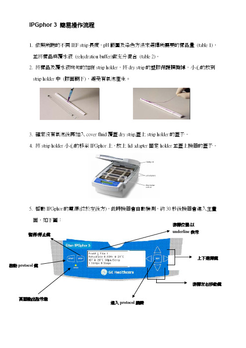
5. 啟動IPGphor 的電源(位於左後方),此時機器會自動檢測,約30秒後機器會進入主畫面,如下圖:暫停/停止鍵 高壓輸出指示燈 啟動protocol 鍵6.利用面板上的上下鍵選擇所需的protocol編號,IPGphor 3最多可以儲存10組protocol,利用左右鍵移動游標至File的位置,利用上下鍵選擇數字及字母編輯 protocol名稱。
7.利用左右鍵移動游標至Rehydration溫度與時間的設定位置,利用上下鍵輸入所需的條件。
同樣地可利用左右鍵移動游標至IEF溫度及電流的設定位置,利用上下鍵輸入所需的條件。
8.按下EDIT鍵進入IEF step的設定,在每個protocol中共有9個步驟S1-S9可供設定,利用左右鍵移動游標至各種設定之下,再使用上下鍵去輸入所需的條件,各種設定分述如下:9.在每個步驟下有step-n-hold及gradient二種不同的模式可選擇,所代表的意義是電壓上升情況的選擇,如下圖:利用左右鍵移動游標至step 的s ,再利用上下鍵則可切換Step 及Grad 兩種不同的設定模式。
10. 利用左右鍵移動游標至電壓設定處,再利用上下鍵選擇所需的電壓。
PsxView3_31 使用说明书
PsxView 3.31 使用说明书目录一、功能介绍: (2)1.文件处理 (2)1.1.打开: (2)1.2.保存: (2)1.3.另存为: (2)1.4.写参数: (2)1.5.写参数文件到PSX600: (2)1.6从PSX600里读参数文件: (2)1.7.程序升级: (3)1.8.导出文件: (3)2.参数配置: (3)2.1工作环境设置: (3)2.1.1标识、GPS、以太网: (3)2.1.2:PSX600信号配置: (4)2.1.3:串行口设置: (4)2.1.4:远传配置: (5)2.2站内数据库配置 (6)2.3远传数据库配置 (6)2.4合并遥信库配置 (7)2.5液晶面板监控库配置 (8)3.四遥数据 (8)3.1.遥测数据: (8)3.2.遥信数据: (8)3.3脉冲数据: (9)3.4遥控数据: (9)4.高级选项 (9)4.1计算机串口设置: (9)4.2修改参数模板: (9)4.3读入装置条目号: (10)4.4设备类型名称代码库: (10)4.5通信监视: (10)4.6参数区: (10)4.7显示PSX600参数区: (11)4.8初始化浮动区: (11)4.9读系统日志文件: (11)二、PSX600现场调试方法及步骤 (11)三、常见的错误及解决方案 (12)四、注意事项及规范 (13)五、通道切换说明 (16)5.1下面以中国101规约双机通道切换为例说明: (16)5.2通道切换板接线方式: (19)一、功能介绍:PSX 600变电站网关配置软件(以下简称PSXView软件)是为配合我公司出品的PSX600系列变电站网关编写的专用配置软件。
通过该软件,可以使繁琐复杂的网关配置变得简单、直观、友好且方便快捷。
PSXView软件兼容Windows95/Windows98/Windows2000操作系统。
PSXVIEW3.3 是在PSXVIEW2.10的升级版本,可兼容原有版本功能,并增加了以太网通讯,遥测系数满度值可调,双机通道自动切换等功能。
瑞思迈呼吸机vpap-iv-vpap-iv-st_使用说明手册
简体中文
欲使用面罩试戴功能:
1 按面罩使用者说明中的要求佩戴面罩。
2 持续按下 至少三秒钟,直至开始输送气压,并显示以下屏幕:
MASK FIT: excelnt
*****
闈㈢僵璇曟埓
零液至晶二显颗示星屏表显示示需面要罩调试整戴星。级,从无星到五颗星。三至五颗星表示佩戴较好或良好。
VPAP IV 和 VPAP IV ST 装置的使用 7
空气输出口
数据卡模块
空气输入口 直流电 交流电
面罩 建议这些装置使用以下 ResMed 面罩系统:
面罩类型
名称
鼻面罩
鼻枕系统 全脸面罩
• • • • •
MUUMMilliirttrrarraagaaggeeeMMViiAMirrcisaatctggiraeevoa™™™™™鼻鼻鼻I鼻I面面面面鼻罩罩罩罩面罩
S 模式范例
S:RAMP 4.0-10.0
>>>>
PS 6.0
模式和压力显示
LK: 10L/min RR: 15 MV: 10.2 VT: 680
泄漏和呼吸信息
S**TiMn Ti 1.5s
TiMx 2.0 1: 1.6
吸气信息
- 1、下载文档前请自行甄别文档内容的完整性,平台不提供额外的编辑、内容补充、找答案等附加服务。
- 2、"仅部分预览"的文档,不可在线预览部分如存在完整性等问题,可反馈申请退款(可完整预览的文档不适用该条件!)。
- 3、如文档侵犯您的权益,请联系客服反馈,我们会尽快为您处理(人工客服工作时间:9:00-18:30)。
/VPAPIII简明操作指南一.前方控制面板的按键及其功能
按键功能
上翻/下翻●在菜单中,使用此键进行各项操作
前键(开关键)●开始和停止治疗
左键●执行上方液晶显示屏里显示的向导功
能(例如“改变”和“应用”)右键●执行上方液晶显示屏里显示的向导功
能(例如“退出”和“取消”)
●从临床菜单屏返回瑞思迈VPAPIII呼
吸机的主屏
右键+下翻键持续按至少3秒钟,从瑞思迈VPAPIII呼吸
机的主屏进入临床菜单
二.日常使用步骤
1.接上电源线,打开呼吸机后部开关,呼吸机进入自检,待呼吸机自检完成。
2.给病人佩带好面罩,再连接上呼吸回路,按开关键进行开机治疗。
3.结束治疗时,按开关键停机,给取下病人面罩。
如常时间不用请关掉呼吸机后部开
关。
三.改变治疗参数设置步骤
1.接上电源线,打开呼吸机后部开关,呼吸机进入自检,待呼吸机自检完成。
2.同时按右键﹢下翻键持续至少3秒钟以上,进入临床菜单。
3.要完成参数值的改变,在临床菜单中请注意使用:
●上翻/下翻键进行该范围内选项的滚动
●按左键进入菜单,进行功能选择操作
●按右键退出菜单,退出菜单不影响正进行的操作。
临床菜单详见第二页
VPAP III 临床设置菜单
模式选择
吸气压
呼气压
呼吸频率
呼吸转换时间
最大吸气压时间
最小吸气压时间
吸气触发灵敏度
呼气触发灵敏度
面罩漏气报警
自动开关机
面罩类型
湿化器类型
管路长度
最大延迟时间
开始压力
基本参数设置完成后连续按撤销键可以返回主见面如下:
通过上下键可以查看
LK表示漏气量RR表示呼吸频率MV表示分钟通气量VT表示潮气量
表示当次吸气由病人自主呼吸触发表示当次呼气由病人自主呼吸触发
Ti表示吸气时间1:2.5表示机器检测到的吸呼比
清洁消毒
面罩、管路、湿化器水罐需要消毒。
先用中性洗涤剂洗涤,清水冲洗干净,2-3%戊二醛浸泡30分钟(注意湿化器外面不能浸泡,只能消毒内壁),蒸馏水清洗干净,凉干,不得防入阳光直晒,否则容易老化。
面罩头带不能浸泡消毒和洗涤。