Sdc10操作手册
SD10-快速入门指南

This agreement is made under the Laws of England.
LICENCE NO: ...........................................................................
REGISTRATION DATE: ...........................................................
Licenses and Trademarks
The SD10 logo and SD10 name are trademarks, and Digico UK Ltd and the Digico UK Ltd logo are registered trademarks of Digico UK Ltd. Microsoft is a registered trademark and Windows is a trademark of Microsoft Corp. Digico (UK) Ltd
Unit 10
Silverglade Business
Park Leatherhead Road
Chessington
Surrey
KT9 2QL
England
Telephone:
+44 (0)1372 845600
Fax:
+44 (0)1372 845656
Email:
sales@
4. The Customer agrees not to attempt to decompile the object code of the Product otherwise than in circumstances specifically
士林 SDC 系列驱动器 V1.00-01 简易说明书

士林SDC 系列驱动器 V1.00-01 简易说明书SDC-010A2(U)/ SDC-020A2(U)/SDC-040A2(U)/SDC-075A2(U)/SDC-100A2(U)非常感谢您选择士林SDC 系列驱动器。
本说明书将对产品的使用及注意点进行说明。
在安装使用前请务必认真阅读本说明书,以便正确安全地使用驱动器。
1.安全注意事项注意安全事项请合格的专业人员进行安装、操作、维护检查。
在本说明书中,将安全注意事项等级分为“警告”和“注意。
警告:不正确操作会造成危险情况,将导致死亡或重伤的发生。
注意:不正确操作会造成危险情况,将导致一般或轻微伤害或物体损坏。
警告驱动器通电中不可打开其前盖板。
并且不可在前盖板卸下的状态下运行驱动器。
否则可能会接触到高电压的端子和充电部分注意各个端子上加的电压只能是操作手册上规定的电压。
否则会造成故障或损坏。
2. 产品型名 ● 驱动器型名S D C_(1)(2)(4)(3)(5)(6)_(7)x y(1) 驱动器代码:以SD 代表伺服驱动器(2) 机种代码:C (3) 驱动器容量:马达输出功率。
将马达输出功率乘1/10后以三码数字表示.例:020表示200W ;100表式1000W (4) 通讯类型:A :Modbus 通讯,C :CANOpen 总线(开发中) (5) 电源型式:输入电源规格。
2:单相 200~240VAC(6) 安规认证:符合CE 但不符合UL 代码为空;既符合CE 又符合UL ,代码为“U ” (7) 士林定义/市场别/客户别…:例: 市场别:TW 台湾;CN :中国…客户别:A1…ZZ(由英文字A~Z 及数字0~9之组合而成) 其他定义… ●马达型名(1) 伺服马达代码:SM 代表伺服马达 (2) 机种代码:E(3) 惯量分类:依马达惯量代码如下:(4) 马达容量:马达输出功率(5) 额定转速:马达的额定输出转速(6) 编码器型式:士林伺服马达编码器型式((SDC 暂不支持光编))(7) 刹车与油封:马达是否附刹车与油封,依下列代码表示之:(8) 键槽与出线型式:马达是否有键槽及出线型式选择,依下列代码表示之:(9) 安规认证:马达通过的安规认证,依下列代码表示之3.安装环境4.安装及配线说明⑥为不使驱动器的散热效果降低,请务必进行纵向安装:⑥为了确保驱动器冷却所需的通气空间及接线空间,请务必遵守下图中所示的安装条件:·单机安装时:·多台安装时:5.端子接线图士林伺服驱动器电源接线为单相电源,图中,Power ON 为a 接点,Power OFF 与Alarm Processing 为b 接点。
艾默生SDC空调使用说明手册-推荐下载
艾默生SDC空调使用说明手册一、设备用途向地下吹风的打空调,用于机房温湿度调节。
二、接口类型通讯接口采用RS485/232方式。
信息传输方式为异步方式,起始位1位,数据位8位,停止位1位,无校验。
数据传输速率为1200、2400、4800、9600和19200bps可以设置。
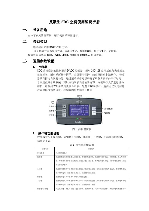
三、通信参数设置1、控制器SDC系列空调的控制器为PACC控制器,采用240*128点阵蓝色背光液晶显示屏显示,用户界面操作简单。
多级密码保护,能有效防止非法操作。
控制器具有掉电自恢复功能。
通过菜单操作可以准确了解各主要部件运行时间。
专家级故障诊断系统,可以自动显示当前故障内容,方便维护人员进行设备维护。
可存储200多条历史事件记录,配置RS485接口,通信协议采用信息产业部标准通信协议,控制器面包那如图1所示图1 控制器面板2、操作键功能说明控制器有5个操作键,分别是开/关键、退出键、上移键、下移键和回车键。
功能见下表:表1 操作键功能说明按键名称功能说明开/关机键开启和关闭机组退出键按此键推出本级菜单进入上级菜单;参数修改过程中,按此键可放弃修改;长按此键,进入帮助菜单,帮助菜单将详细列出数据区域的最大值、最小值、默认值及简单描述;在有报警发生时,按此键可消除报警声。
上移键按此键可将菜单中的光标上移或增加显示的参数设定值;如果该设定参数为复选项,按此键则滚动显示相关选项;当菜单多屏显示时,按此键可向上翻页。
回车键按此键可进入下一级菜单或确定参数设定值。
下移键按此键可将菜单中的光标下移或减小显示的参数设定值。
如果该设定参数为复选项,按此键则滚动显示相关选项;当菜单多屏显示时,按此键可向下翻页。
回车键+上移键此为组合键,按住回车键,再按上移键,再放回车键,完成一次按键操作。
该组合键用于查看上一空调机的状态。
回车键+下移键此为组合键,按住回车键,再按下移键,再放回车键,完成一次按键操作。
该组合键用于查看下一空调机的状态。
3、控制界面3.1 主界面图2 主界面界面上包含三类机组工作图标,分别是动画运行状态图标、锁定状态图标和开关机主备状态图标,这些图标告知操作员机组正在何种运行模式下运行。
SD模块用户操作手册
目录(1)标准订单用于有赊销的情况,常用于省公司销售和分公司有赊销的销售。
(2)标准订单(参照合同)用于有赊销的情况,同样用于省公司销售和分公司有赊销的销售,但该订单适用于事前签订了合同的情况。
(3)现金订单(无应收)多用于市(县)公司无赊销的销售。
(4)库割流程在同一油库内将属于省公司的油料库割给分公司,只是油料所有权的转移,并不发生实际的油料移动,没有损耗,仅仅是帐面的处理。
(5)寄售补货订单用于将油品从我方油库转移给寄售方,但发出货物的物权仍在我方,不转移给客户,作为我方在客户方的寄售库存。
(6)寄售发货订单在寄售方将寄售货物的售出部分与我方进行结算时使用。
(7)直发流程在某客户与公司有一笔销售业务往来,客户到炼厂直接提货时使用。
(8)销售代保管发货流程描述的是对客户寄存在我公司的代保管量进行发货的过程。
(9)合同是在销售业务进行之前,业务员与客户按照销售需求协商,呈销售经理审批核准后与客户签订的。
(10)错误发票处理流程(11)退货流程是指销售业务发生后,客户因质量等原因要求退货时而发生的。
(12)发票打印流程(13)分公司提货单打印一、标准订单流程(一) 创建标准订单1. SAP交易代码VA012.输入:销售组织分销渠道部门销售办事处(订单类型ZS03)3.输入订单相关内容:售达方采购订单编号(填入销售人员)交货工厂付款条件物料订单数量4.点击“”,通过修改销售指导附加价输入价格,再点击“”返回5.点击“”(显示凭证项目细节),点“会计”,输入收付方式,”指定”栏位内输入销售办公室的代号6.点击“装运”,输入:装运类型特殊处理标志7.保存订单,记录订单号(二)针对标准订单创建交货单并发货过帐1. SAP交易代码VL01N2.输入:装运地点订单号3.输入交货单相关内容:评估类型库位,点击“外部细节”,选择运输方式4.转到/表头/文本,输入:提单流水号5. 点击“发货过帐”,记录交货单号(三)开立发票1.SAP交易代码VF012.输入交货单号,转到/表头/文本,输入:开票员姓名,点击“(执行)”,保存发票二、标准订单(参照合同创建)(一) 创建标准订单(参照合同)1. 创建订单:SAP交易代码VA018.输入:销售组织分销渠道部门销售办事处9.点击“带参照创建”,输入合同号,点击“复制”10.输入订单相关内容:采购订单编号(填入销售人员)11.点击“”,点“会计”,输入收付方式12.点击“装运”,输入:装运类型特殊处理标志13.保存订单,记录订单号.(二)创建交货单并发货过帐1. SAP交易代码VL01N2.输入:装运地点订单号3.输入交货单相关内容:评估类型库位,点击“外部细节”,选择运输方式4.转到/表头/文本,输入:提单流水号5. 点击“发货过帐”,记录交货单号(三)开立发票1. SAP交易代码VF012.输入交货单号,点击“执行”,保存发票三、现金订单(无应收)流程(一) 创建现金订单(无应收)订单1. SAP交易代码VA012.输入:销售组织分销渠道部门销售办事处(定单类型ZS18)3.输入订单相关内容:售达方采购订单编号(填入销售人员)交货工厂付款条件物料订单数量4.点击“”,通过修改销售指导附加价输入价格,再点击“”返回5.点击“”,点“会计”,输入收付方式6.点击“装运”,输入:装运类型特殊处理标志7.保存订单,记录订单号(二)针对现金订单发货过帐1. SAP交易代码VL02N2.输入现金订单对应的交货单号3.输入交货单相关内容:评估类型库位,点击“外部细节”,选择运输方式4.转到/表头/文本,输入:提单流水号5. 点击“发货过帐”,记录交货单号(三)开立发票1. SAP交易代码VF012.输入现金订单号,点击“(执行)”,保存发票四、库割流程(一)创建库割订单1.SAP交易代码ME272.输入:供货工厂(发出库)订单类型(ZJNB)采购订单日期(系统默认当日)采购组织采购组工厂(收进货)库存地点(逻辑库存地点)3.点击“新采购订单”输入订单相关内容:物料数量4.点击“”,输入发票提供者5.返回并保存,记录库割订单号(二)针对库割订单创建交货单并发货过帐1. SAP交易代码VL10B2.点击“采购订单”输入库割订单号,点击“”3.选中一行点击“后台”,回车,选择“全部”,点击“”,点击“”4.双击交货单号,点击“”,输入评估类型和库位,点击“发货过帐”(三)开立发票1. SAP交易代码VF012.输入交货单号,点击“(执行)”,保存发票五、寄售补货订单流程(一) 创建寄售补货订单1. SAP交易代码 VA012.输入:销售组织分销渠道部门销售办事处订单类型(ZS07)3.输入订单相关内容:售达方采购订单编号(填入销售人员)交货工厂付款条件物料订单数量4.保存订单,记录订单号(二)针对寄售补货订单创建交货单并发货过帐1. SAP交易代码 VL01N2.输入:装运地点订单号3. 输入交货单相关内容:评估类型库位4.点击”外部细节”,选择运输方式5.点击“发货过帐”,记录交货单号六、寄售发货订单流程(一) 创建寄售发货订单(参照寄售补货订单)1. SAP交易代码 VA012. 输入:销售组织分销渠道部门销售办事处订单类型(ZS08)3. 回车,带参照创建界面,输入寄售补货订单号点击“复制”4. 输入订单相关内容:采购订单编号(填入销售人员)5.保存订单,记录订单号.(二)针对寄售发货订单创建交货单并发货过帐1.SAP交易代码 VL01N2.输入:装运地点订单号3.输入交货单相关内容:评估类型库位4.点击“发货过帐”,记录交货单号(三)开立发票1.SAP交易代码 VF012.输入交货单号,点击“(执行)”,保存发票七、直发流程(一) 创建订单1. SAP交易代码VA012. 输入:销售组织分销渠道部门销售办事处(订单类型ZS12)3.输入订单相关内容:售达方采购订单编号(填入销售人员)交货工厂付款条件物料订单数量4. 点击“”,通过修改销售指导附加价输入价格,再点击“”返回5. 点击“”,输入该笔业务的货款支付方式式:点击“会计”,输入收付方式6. 保存订单,记录订单号(二)创建采购订单1.SAP交易代码ME572.输入采购申请号,点击“”,在采购申请前小框内打勾,点击“自动分配”3.选中采购合同号,回车,在采购申请前小框内打勾,点击“分配”4.选中框架协议号(采购合同号),点击“处理分配”5.输入:订单类型(ZJS1)采购日期采购组采购组织6.输入发票提供者(采购业务的结算方)7.选中凭证总览中的采购申请,点击“”,检查抬头/合伙人中的发票提供者是否存在(若不存在,则输入发票提供者)8.在项目细节中点击“外部细节”,输入卡车编号。
SDC量热仪说明书正文
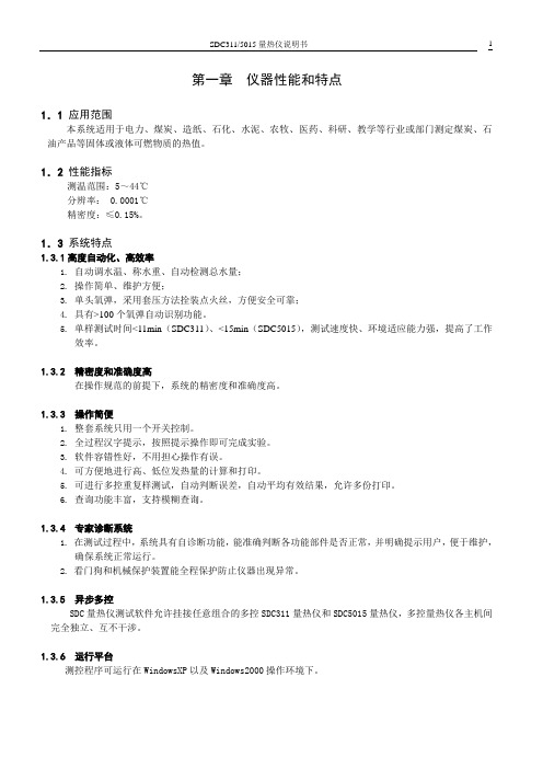
第一章仪器性能和特点1.1 应用范围本系统适用于电力、煤炭、造纸、石化、水泥、农牧、医药、科研、教学等行业或部门测定煤炭、石油产品等固体或液体可燃物质的热值。
1.2性能指标测温范围:5~44℃分辨率: 0.0001℃精密度:≤0.15%。
1.3系统特点1.3.1高度自动化、高效率1.自动调水温、称水重、自动检测总水量;2.操作简单、维护方便;3.单头氧弹,采用套压方法拴装点火丝,方便安全可靠;4.具有>100个氧弹自动识别功能。
5.单样测试时间<11min(SDC311)、<15min(SDC5015),测试速度快、环境适应能力强,提高了工作效率。
1.3.2 精密度和准确度高在操作规范的前提下,系统的精密度和准确度高。
1.3.3 操作简便1.整套系统只用一个开关控制。
2.全过程汉字提示,按照提示操作即可完成实验。
3.软件容错性好,不用担心操作有误。
4.可方便地进行高、低位发热量的计算和打印。
5.可进行多控重复样测试,自动判断误差,自动平均有效结果,允许多份打印。
6.查询功能丰富,支持模糊查询。
1.3.4 专家诊断系统1.在测试过程中,系统具有自诊断功能,能准确判断各功能部件是否正常,并明确提示用户,便于维护,确保系统正常运行。
2.看门狗和机械保护装置能全程保护防止仪器出现异常。
1.3.5 异步多控SDC量热仪测试软件允许挂接任意组合的多控SDC311量热仪和SDC5015量热仪,多控量热仪各主机间完全独立、互不干涉。
1.3.6 运行平台测控程序可运行在WindowsXP以及Windows2000操作环境下。
第二章仪器组成及工作原理2.1 仪器组成SDC量热仪主要由SDC量热仪主机、SD—YD氧弹、SD—CYQ微型充氧器、SD测控接口、SD测控软件、计算机、打印机等组成(见图2-1)。
此外,用户还可以选配电子天平、天平接口、SD天平称量软件以及相关仪器配件。
图2-12.1.1 SDC 量热仪主机1.结构示意图(见图2-2);2.特点:体积小、重量轻,自动定容水量、调节水温,环境适应能力强,操作简单方便。
PRIMEDIC除颤监护仪DM10使用手册

0. 目录页码1. 安全指南 32. 仪器说明 53.准备工作13 3.1 蓄电池的充电133.2 心脏除颤仪/心电图监护器的配置(启动莱单)144.心脏除颤仪的操作16 4.1 心脏除颤仪的启动和关闭/自我检测16 4.2 同步和异步驱动16 4.3 能量选择17 4.4 充入能量18 4.5 电极的放置19 4.6 能量的释放194.7 儿童专用电极205.心电图监护器的操作21 5.1 心电图导联的选择21 5.2 信号强度的调节22 5.3 心缩期音的音量22 5.4 心率报警的启动225.5 滤波器235.6 心电图电极的放置246. SpO2-监护器的操作(仅DM30型号)256.1 SpO2-传感器的联接256.2 选择正确的SpO2-传感器276.3 调节SpO2警报287. 打印机的操作297.1 记录心电图信号297.2 每次放电后自动记录输出(自动打印) 307.3 存储器数据的打印317.4 安装打印纸32 8.PRIMEDIC起搏模块的操作338.1 起搏模块的联接338.2 起搏-/除颤电极的置放348.3 起搏器的开启和关闭368.4 操作方式的调节388.5 刺激频率的调节398.6 刺激强度的调节398.7 起搏的开始和停止408.8 起搏过程中进行除颤/通过枕电极除颤429. PRIMEDIC体内除颤(I/D)模块的操作439.1 体内除颤模块的联接439.2 体内除颤用勺电极的联接449.3 通过勺电极进行除颤4410. PRIMEDIC遥控除颤(R/D)模块的操作4510.1遥控除颤模块的联接4510.2 枕电极的置放4610.3 遥控除颤导线的联接4610.4 通过枕电极进行遥控除颤4711. 充电器的使用4712. 可换蓄电池的使用4812.1 蓄电池的更换4912.2 在充电器上同时对蓄电池充电5013. 维护和保养 5114. 废弃处理5215. 技术数据、配件和图示5315.1 PRIMEDIC DEFI-MONITOR DM10和DM30的技术数据53 15.2 配件5615.3 图示5716. 保修条款5817. 附录59A1蓄电池部件的一般指南和规定59A2使用心脏除颤仪的一般指南和规定61A3使用血氧饱和度检测的一般指南67A4对电压一时间函数的说明69A5对监护器图象和输出的说明71A6安全技术检验75PRIMEDIC是Metrax GmbH, Rottweil的注册商标1.安全指南您所购买的PRIMEDIC DEFI-MONITOR是根据在紧急情况下使用的高要求而设计的。
欧瑞传动SD10-Z系列伺服驱动器使用手册说明书
前言感谢您选用欧瑞传动电液伺服控制系统!同时,您将享受到我们为您提供的全面、真诚的服务。
SD10-Z系列伺服驱动器容量范围广,能够完美地实现伺服油泵控制,亦能实现大部分通用型伺服功能需求。
是目前市场上性价比较高的中大功率伺服驱动器。
本手册将为您提供安装调试、操作使用、故障诊断及日常维护的有关注意事项,在安装、使用前请仔细阅读。
本手册随驱动器一起提供,请妥善保管,以备以后查阅和维护使用。
当您在使用中发现任何问题,而本手册无法为您提供解答时,请与本公司联系咨询。
我们的专业技术服务人员将竭诚为您服务,并希望您能继续选用我们的产品,敬请提出宝贵的意见和建议!本公司致力于产品的不断改善和功能升级,手册提供资料如有变更,恕不一一通知。
最新及详细版使用手册会在公司网站()上进行公布。
■安全标识本产品的安全运行取决于正确的安装和操作以及运输与保养维护,请务必遵守本手册中使用的如下安全标识:错误的操作将引发危险情况,导致人身伤亡。
错误的操作将引发危险情况,导致轻度或中度人身伤害,损坏设备。
另外,该标识中所述事项有时也可能造成严重的后果。
驱动器及电机上标识符的意义如下:电压高,有电击危险。
表面热,禁止触摸。
目录前言 (1)1.1 产品确认事项 (4)1.2 伺服驱动器的铭牌 (4)1.3 伺服电机的铭牌 (4)1.4 驱动器命名规则 (5)1.5 伺服电机命名规则 (6)1.6 产品外观 (7)1.7 安全须知 (7)1.7.1 安装、布线注意事项 (7)1.7.2 运行、维护注意事项 (8)1.7.3 废弃注意事项 (8)2 伺服系统技术规范及选型 (9)2.1 伺服驱动器技术规范和参数 (9)2.1.1伺服驱动器技术规范 (9)2.1.2伺服驱动器主要参数和外围电气元件选型指导 (10)2.1.3伺服驱动器外围配线、磁环使用指导 (11)2.2 伺服电机技术规范和参数 (12)2.2.1 伺服电机技术条件 (12)2.2.2 伺服电机主要参数 (13)2.3 伺服系统推荐配置表以及选型计算 (14)2.3.1 各品牌油泵的推荐表 (14)2.3.2 伺服驱动器、电机、油泵的选型计算方法 (15)2.3.3伺服、电机、油泵的组合配置 (15)3 产品安装 (17)3.1 驱动器安装 (17)3.1.1 驱动器结构尺寸 (17)3.1.2 驱动器安装 (19)3.2 伺服电机安装 (19)3.3 制动单元及制动电阻 (20)4.1 电液系统构成 (22)4.2 电气连接 (23)4.2.1 主电路接线示意 (24)4.2.2 控制端子功能简介和接线示意图 (24)4.2.3 拨码开关介绍 (26)5 操作面板和功能参数 (27)5.1 面板显示说明 (27)5.2 面板操作 (27)5.3 参数设置 (28)5.4 功能码区内和区间的切换 (28)5.5 面板显示内容 (29)5.6参数设定 (30)5.6.1 基本参数 (30)5.6.2运行控制 (30)5.6.3 多功能输入输出 (32)5.6.4 模拟量检测和输入输出 (34)5.6.5 能耗制动和保护控制 (35)5.6.6 电机控制参数 (36)5.6.7 压力控制参数 (38)5.6.8 多泵合流控制 (41)5.6.8.1多泵合流控制参数 (41)5.6.8.2多泵合流控制示意图 (43)6 电液机整机调试步骤 (44)7 故障分析处理 (46)8 日常检查和保养 (52)8.1定期检查 (52)8.2易损件更换 (52)8.3存储 (52)附录一功能码速查表 (53)附录二电液机卡说明 (67)附录三伺服电机结构尺寸示意图 (68)1使用须知1.1 产品确认事项产品到货之后,请对如下项目进行检查并确认。
SDC安全门控系统产品说明书
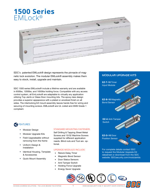
SDC’s patented EMLock® design represents the pinnacle of mag-netic lock evolution. The modular EMLock® assembly makes them easy to stock, install, upgrade and maintain.SDC 1500 series EMLocks® include a lifetime warranty and are available in 650lbs, 1200lbs, and 1650lbs holding force. Compatible with any access control system, all EmLocks® are adaptable to virtually any application utilizing Top Jamb or Glass Door mounting kits. The epoxy-less design provides a superior appearance with a plated or anodized finish on allsides. The interlocking EZ mount assembly leaves hands free for wiring and securing of mounting screws. EMLocks® are UL Listed and ANSI Grade 1 compliant.1500 SeriesEMLock®FEATURES• Modular Design • Modular Upgrade Kits • Field Upgradeable withoutremoving from the frame• Uniform Design &Installation• Identical Housing, Template& Accessories• Quick Mount AssemblySTANDARD MOUNTING FASTENERS Self Drilling & Tapping Sheet Metal Screws and 10/32 Machine Screws supplied for different application needs. Blind nuts and Tool are op-tional.UPGRADE MODULES INCLUDE:• Relock Delay Timer • Magnetic Bond Sensor • Door Status Sensors • Anti-Tamper SwitchSecurity Door ControlsSECURITY DOOR CONTROLS ACCESS & EGRESS SOLUTIONS - THE LOCK BEHIND THE SYSTEM21510 SERIES GRADE 11650 LB / 748 KG HOLDING FORCE1570 SERIES GRADE 11200 LB / 544 KG HOLDING FORCE 3 WATTS ENERGY SAVER1580 SERIES GRADE 1650 LB / 295 KG HOLDING FORCESPECIFICATIONSVoltage 12/24VDC Voltage Sensing InputSingle350mA @ 24VDC; 670mA @ 12VDC11” L x 2-3/4” H x 1-9/16” D Double700mA @ 24VDC; 1.34A @12VDC22” L x 2-3/4” H x 1-9/16” DSPECIFICATIONSVoltage 12/24VDC Voltage Sensing InputSingle125mA @ 24VDC; 250mA @ 12VDC11”L x 2-3/4”H x 1-9/16”DDouble 250mA @ 24VDC;500mA @ 12VDC22” L x 2-3/4” H x 1-9/16” DSPECIFICATIONSVoltage 12/24VDC Voltage Sensing InputSingle220mA @ 24VDC; 440mA @ 12VDC8-3/4”L x 2-1/8”H x 1-1/4”D Double440mA @ 24VDC; 880mA @ 12VDC17-1/2” L x 2-1/8” H x 1-1/4”D15821581151315121511UL Listed U.S. & Canada: GWXT Auxiliary LocksCVXJ Burglary Resistant Electrically Operate-Door LockUL10C: Position Positive Pressure CompliantUBC: Classified in accordance with Uniform Building Code standard 7-2 “Fire Test for Door Assemblies”ANSI/BHMA A156.23: Grade 1, one million cycles BHMA CertifiedCSFM: California State Fire Marshal Listed 3774-0324:100MEA: City of New York 61-95-E157315721571LISTINGS & PERFORMANCE SPECIFICATIONS1511 Single EMLock®1512 Double EMLock®1513 Single, split armature for pair of doors1571 Single EMLock®1572 Double EMLock®1573 Single, split armature for pair of doors1581 Single EMLock®1582 Double EMLock®MODELSFIELD INSTALLED OPTION KITS Ordered separately for field upgrade. For complete details contact SDC to request more information on Modular Upgrade Kits.EZ-T-10 Adjustable Timer InputModule: Specify (1) for single or double EmLocks®(not available with 1580 series) EZ-D-10 1510, 1570 Door Position Sensor Module: Specify (2) for double EMLocks®(not available with 1513 and 1573) EZ-D-80 1580 Door Position Sensor Module: Specify (2) for double EM-Locks®EZ-B-10 1510, 1570 Magnetic Bond Sensor Module: Specify (2) for double EMLocks®(Not available with 1513,1573) EZ-B-80 1580 Magnetic Bond Sensor Module: Specify (2) for double EM-Locks®EZ-A Anti-Tamper Switch Module: Indicates cover plate removal.EZ-1510W Holding Force Module: Ex-change a 1200lb wire coil (1570 series) with this 1650lb wire coil.Specify (2) for double EMLocks® EZ-1570W Energy Saver Module: Save on power supply and long term energy costs by exchanging 8.4 Watt, 1650lb coil with 3 Watt, 1200lb hold-ing force coil. Specify (2) for double EMLocks®All available throughACCESSORIESSpecify housings with your EMLocks ®. Example : 1511V-30; 1512V-60DC-2DC-1Anodized FinishesV Aluminum (standard) Y Black anodizedPainted FinishesC Brass powder coat X Dark bronze powder coat Plated Finishes (special order)P Bright chrome Q Dull chromeFEATURESVertical Housings - Side jamb mount, providing 2400 or 3300 lbs of holding force.FINISHACCESSORIESPRE-DRILLED & TAPPED HEADER BRACKETMachined Wire ChaseHoles Pre-Drilled & Countersunk For Frame MountingPre-Drilled and TappedLock Mounting HolesUF81VUF11VAluminum frames with blade stop - lowers EmLock below blade stop. Concrete filled hollow metal frames provides multiple points for concealed wire entry• Pre-drilled and tapped specifically for 1511, 1571, 1581 EmLock • Machined wire chase provides multiple points for concealed wireentry from concrete filled frames.• 628 Aluminum AnodizedFEATURESUsed in lieu of angle brackets, the Universal Header Bracket provides a faster mounting solution, saving time and labor costs for several EmLock models. Reduce potential for mis-sized and misaligned mounting holes, broken taps, removal of broken taps. Combined with interlocking. E-Z mount assembly, save up to a half days labor with the instal-lation of 12 locks.• Solid 1” bar provides higher security and superior aesthetics.• Machined wire chase provides concealed and secure wiring• Multiple pre-drilled and tapped mounting holes to accommodate theuse of several different locks on either 4” or 4.5” aluminum framesFEATURESFINISHV 628 Aluminum (standard)C 605 Bright BrassD 606 Dull BrassP 625 Bright Chrome Q 626 Dull Chrome X 313 Dark Bronze Y 335 BlackSecurity Door ControlsSECURITY DOOR CONTROLS ACCESS & EGRESS SOLUTIONS - THE LOCK BEHIND THE SYSTEM659mm51mm2"BA2 5/16"FILLER PLATESFor 22” (559mm) Double Emlock Models 1512 / 1572PART # A x BFP21 1/8” x 1-1/4” FP22 1/4” x 1-1/4” FP23 3/8” x 1-1/4” FP24 1/2” x 1-1/4” FP255/8” x 1-1/4”For 17-1/2” (445mm) Double Emlock Model 1582PART # A x BFP30 1/8” x 1-1/4” FP31 1/4” x 1-1/4” FP32 3/8” x 1-1/4” FP33 1/2” x 1-1/4” FP34 5/8” x 1-1/4”For 10”-11” Single Emlock & Exit CheckModels 1511, 1513, 1571, 15731511S, 1511T, 1511DEV, 1571DEV PART # A x B FP11 1/8” x 1-1/4” FP12 1/4” x 1-1/4” FP13 3/8” x 1-1/4” FP14 1/2” x 1-1/4” FP155/8” x 1-1/4”For 8-3/4” Single Emlock & Exit Check Models 1581, 1581DEPART # A x B FP01 1/8” x 1-1/4” FP02 1/4” x 1-1/4” FP03 3/8” x 1-1/4” FP04 1/2” x 1-1/4” FP05 5/8” x 1-1/4”2"2 5/16"59mm51mmGlass DoorTop RailGlassARMATURE MOUNTING PLATEAR11Y Armature mounting plate for 1511, 1571335 Black Anodized (Specify two for models 1512, 1572)AR11YD A rmature mounting plate with DPS for 1511, 1571.335 Black Anodized(Specify two for models 1512, 1572)The AR Mounting plate provides a solution for mounting the EMLock® armature to the top rail of herculite, aluminum and glass, wood and hollow metal doors that do not permit the use of thru bolts.APPLICATIONMODELSMODELSAPPLICATIONFor extension of the stop to provide a proper mounting surface on the underside of the header See Figure 1B.ANGLE BRACKETSREUSABLE HEAVY DUTYDRILL FIXTUREBLIND NUTPLACEMENT TOOLINTERLOCKING QUICK MOUNT ASSEMBLY1511-DF1581-DFadequate mounting surface. See Figure 1C.© 2018 SECURITY DOOR CONTROLS Security Door ControlsLIT-EMLOCK-BROCHURE 04/18[t] 800.413.8783 805.494.0622 [f] 866.215.3138 801 Avenida Acaso, Camarillo, CA 93012 PO Box 3670, Camarillo, CA 93011TYPICAL DOOR APPLICATIONS1511 1571 1581• AB Angle bracket • Aluminum frame• Aluminum & glass door • Push side mounting 1511-HDB1 1571-HDB11581-HDB1• Glass door mounting kit • AB series angle brackets • Metal or aluminum frame • Glass door w/o top rail • Push side mounting 1511-(36) 1571-(36)• Full width architecturalhousing• Specify length(30”, 36”, 40”, 48”)• Aluminum frame• Aluminum & glass door • Push side mounting 1511 1571 1581• Hollow metal frame • Wood/hollow metaldoor• Push side mounting1511-TJ1 1571-TJ11581-TJ81• Top jamb mounting kit • Hollow metal frame• Wood or hollow metal door • Pull side mounting 1512 1572 1582• AB Angle bracket • Aluminum frame• Aluminum & glass doors • Push side mounting1513 1573• Split armature• Hollow metal frame • Wood or hollowmetal doors• Push side mounting1512 1572 1582• Hollow metal frame • Wood or hollow metaldoors• Push side mounting1512-HDB2 1572-HDB21582-HDB2• HDB Glass door mountingkit• AB series angle bracket • Metal or aluminum frame • Glass door without top rail • Push side mountingCOMMUNICATING BATHROOM EMLOCKS®Single hospital bathroom shared by two patient rooms.SYSTEM OPERATIONBoth doors must be closed to lock.Activating CB401A (B) locks both doors.Activating CB401A (B) again unlocks both doors.When doors are locked, activating either CB401B (C) emergency release will unlock both doors.Both doors will unlock automatically via signal from fire panel.SYSTEM COMPONENTS (A)Fail Safe locks with door position switch. Example: 1511-DPS(B) CB401A System activation push switch.(C)CB401B Emergency release push switch to be mounted above each door. CB701B key switch optional.(D)631RF-UR1 Power Supply with Fire Panel Tie-In and Communicating Bath ControllerFROM FIRE PANEL 110 VAC INPUTPOWER SUPPYAABCC D。
SD10伺服说明书(精简版)
目录
3.4.3 电磁抱闸的配线.............................................................................................................. 24 四 运行.............................................................................................................................................. 25
3.4 输入输出信号(CN3)的连接实例...................................................................................... 22 3.4.1 模拟量速度模式的连接实例.......................................................................................... 22 3.4.2 位置脉冲模式的连接实例.............................................................................................. 23
3.3 输入输出信号配线 ................................................................................................................. 14 3.3.1 输入输出信号连接器端子排列...................................................................................... 14 3.3.2 输入输出信号端子名称及功能...................................................................................... 15 3.3.3 可编程输入信号端子功能设定...................................................................................... 18 3.3.4 可编程输出信号端子功能设定...................................................................................... 21
SDC系列智能型除湿装置说明书

SDC系列智能型除湿装置说明书一、产品简介SDC-8000智能型除湿装置是采用半导体制冷除湿方式,主动将密闭空间的潮湿空气在风扇的作用下吸入除湿风道,空气中的水汽经过半导体制冷机构后冷凝成水,再通过导水管排出柜体,可以达到很好的除湿效果。
通过减低空气中含水量,使相对湿度和绝对湿度同时下降,几乎不提高温度,不产生温差带来的负面影响,从根本上杜绝或减少了事故的发生,也不会因高温而加速柜内器件及柜体的老化。
智能型除湿装置把被动防止凝露方式,改为主动引导凝露,有效的防止柜内设备老化、绝缘强度降低、二次端子击穿、材料霉变及钢结构件锈蚀等安全隐患,保证电网安全运行。
设备内部发生凝露引起爬电、闪络事故,一般发生在以下几种情况:一是地区湿度高,天气温度变化大,开关柜底部湿润,有的电缆沟甚至有积水;二是有的开关柜在地下室,湿度高,柜体内温度特别是接近地面的温度低于环境温度;三是有的设备处于暂时停运状态,电气柜内小环境温度就比四周环境温度低,在其表面就极易形成结露,在这种情况下,一旦送电投运,事故就随之发生。
为保证电网系统的安全运行,电气设备的长寿命、安全有效使用,电力系统对柜内防潮、防凝露提出了更高要求。
二、应用范围1、GIS控制柜、高低压开关柜、环网柜、户外端子箱、机械控制柜、箱式变电站、干式变电站等电气设备;2、集成电路,硅晶体,液晶器件,陶瓷器件、阻容元件,有源器件,接插件,SMD器件,CPU,计算机板卡防潮储存;3、物理化学仪器、实验材料、绝缘材料的防潮管理,化学品、药品、食品、纤维、生物制剂的防潮储存。
三、产品特点1、体积小、重量轻、安装方便快捷;2、自动运行与手动除湿功能切换、温度启动值和除湿启动值可调;3、除湿风道主动引凝、排出气体加热降湿,有效达到了对电气柜密闭空间防潮除湿的综合治理;4、湿度、温度传感器24小时实时采样,超出设定启动值自动引凝;5、湿度、温度设置具有记忆功能,不会因为停开机而消失;6、故障显示功能,可快速查找故障点保证正常运行;7、采用专用防潮元件,外壳采用304不锈钢(铝合金材质)结构,保证在潮湿环境下正常工作;8、屏蔽隔离技术的运用,符合GB / T17626-2008的3级标准,保证能够在强电磁场下工作;9、除湿引凝管路,可把引凝后的水排出柜外,同时也可采用储液袋柜外收集。
CT10 用户指南说明书

包装清单部件名称电源管理充电连接正在更新固件入门指南 _01基本操作主屏幕通知面板从商店购买音乐DLNA Link 聆听音乐播放列表管理设置连接至无线网络使用 Bluetooth 均衡器设置设备使用 _02安全预防措施故障排除版权注册商标免责声明规格其他注意事项 _03目录020*********11151719202326293435374042434444455 针微型 USB 电缆: 将本产品连接到 PC 或给本产品充电。
快速入门指南: 介绍使用本产品的基本方法。
保修卡: 如需客户服务,必须提供保修卡。
用户指南: 您可从以下 Activo 网址中下载用户指南: [http: /// > 支持 > 下载]。
为提高产品的性能或质量,恕不预先通知任何内容变更。
包装清单和保修卡USB 电缆5 针微型 USB 端口: 连接到计算机或对设备充电。
3.5 毫米不平衡: 用 3.5 毫米不平衡端口连接入耳式耳机和头戴式耳机以输出声音。
电源: 短按 - 打开或关闭屏幕。
长按 - 打开和关闭设备。
上一首/快退: 短按 - 播放上一首歌曲或者重新开始播放该歌曲。
长按 - 快退。
播放/暂停: 播放/暂停。
下一首/快进: 短按 - 播放下一首音乐。
长按 - 快进。
microSD: 将 microSD 卡插入产品,以查看 microSD 卡中的文件。
音量: 转动滚轮可调整音量。
LCD 触摸屏: 显示屏幕,并且触摸屏幕即可启动。
主按钮: 返回主屏幕。
产品外观以及产品上的印刷和刻印信息可能因型号不同而有所差异。
部件名称上一首/快退下一首/快进播放/暂停microSD触摸屏 LCD 主按钮音量电源重置功能1. 如果出现意外设备故障或者冻结,长按 [电源] 7 秒可强 制进行关闭。
关闭后可以重新启动设备。
32 打开/关闭屏幕1. 打开屏幕后,短按 [电源] 键关闭屏幕。
2. 再次短按 [电源] 键打开屏幕。
Delvcam DELV-HDSD-10 高清数字视频监控系统用户指南说明书

DelvcamDELV-HDSD-10User GuideIMPORTANT SAFETY INSTRUCTIONS:●Please read manual before using this product.●Please keep manual for future reference.●Please read the cautions to prevent possible danger and loss of property●Please enjoy the benefits of convenience, safety, and space-saving from thisTFT LCD monitor in different ways.FEATURES:This product employs integrate circuits, lower power consumption, and lower radiation emission. It has fashion designed appearance and good portability;LED backlight display makes the device much thinner, more power saving;Video (or SDI)、YPbPr、Dual audio and HDMI inputs, to connect with HD camera;High brightness & contrast with flexible folding sun shade cover, makes picture detail much clearer, more vivid outline, stronger sense of hierarchy;178°/ 178°(H/V) wide viewing angles,to provide better viewing effect;1024×768 high resolutionDC 7-24V wide range voltage.CAUTIONS:1.Please do not place the display screen face down on the ground.2.Please avoid heavy impact, do not drop monitor.3.The LCD screen scratches easily. Be sure screen does not come into contactwith sharp objects.4. Please do not block any of the vent hole s.5.Please follow the instructions and trouble-shootings to adjust the product.Other improper adjustment may result in damage. Any further adjustmentmust be performed or conducted by a qualified technician.6.Please unplug the power or remove the battery if long-term no-use, orduring lightning / electrical storms.Contents1. PRODUCT DESCRIPTION (2)2. INSTALLATION OF SUNSHADE COVER (4)3. DV BATTERY MOUNT PLATE (5)4. SETTING MENU (7)5. ACCESSORIES: (9)6. PARAMETERS (10)7. TROUBLE SHOOTING (10)1.PRODUCT DESCRIPTION1. TALLY (indicator light);2. Battery power on/off switch: “‖” is battery power; “O” is power off; “|” isDC power;3. Earphone jack;4. Power indicator light;5. VIDEO: Indicator lights up when signal switch to video state;(No use under the SDI mode);6. YPbPr: Indicator lights up when signal switch to YPbPr state;7. HDMI1: Indicator lights up when signal switch to HDMI 1 state;8. HDMI2: Indicator lights up when signal switch to HDMI 2 state;(Signal switch to SDI state under the SDI mode);9. F1-F4:4 user-definable buttons:Default functions:F1:PeakingF2:False ColorF3:ExposureF4:Histogram10. Knob BRI/M/SEL: Press the knob to access the menu function, pressingthe knob in the menu to return to the previous page or exit the menu.Rotate knob to select an option;Default as Brightness function.11. Knob SAT/ADJ: Press the knob to select main MENU options; rotate knobto confirm the selection and adjust parameter values;Default as Saturation function.12. Knob TINT: Default as Tint function;13. Knob CONTRAST: Default as Contrast function.14. Video signal output / input (Optional: SDI signal input/ output); 15. Y signal input / output; 16. Pb signal input / output; 17. Pr signal input / output; 18. Audio (L/R) input; 19. HDMI 1 signal input;20. HDMI 2 signal input (no use under SDI mode ); 21. HDMI signal loop output (optional);22. Mini USB input (Only for program upgrades, do NOT use if non-professionals)23. Power cable interface (connecting to the battery plate); 24. Speaker;25. TALLY signal input;26. USB output port (DC 5V/0.5A) 27. 4-pin XLR DC power input.Ps: Unavailable under SDI mode 26 (USB 5V/0.5A output power).※ Optional: Without BNC interfaces2. INSTALLATION OF SUNSHADECOVERPushing to close / open sunshade from assigned round area when assembly / disassembly. (i.e. assembly instruction ② / disassembly instruction ①); otherwise assembly / disassembly failed, and even damaged.Assembly instructionsDisassembly instructions3.DV BATTERY MOUNT PLATEStandard mounts processFollowing three types of battery plates are suitable for this device, model F970, QM91D, DU21 & LP-E6 (choose 2 out of 4).MODEL: F-970 MODEL: QM91D MODEL: DU21 MODEL: LP-E6DV Battery Mount Plate:DV Battery Mount Plate Specification:Model DU21 for battery of Panasonic DV:NV-GS/PV-GS/DZ-MV/GS/H28/H258/H288GK series, comply withPanasonic battery DU06/VBD140/SANYO DZhs301sw/HitachiDZ-HS303SW/BZ-BP14S/DZ3200/BP07W.Model QM91D for battery of SONY DV:DSCR1/F/S/MVCCD/E/HC15E/HC1E/AE1u/DCRTRV828/E/CCD-TRV116/DCR-DVD/PS105K/300K/10P/1E series.Model F970 for battery of SONY DV:DCR-TRV series, DCR-TRV E series, VX2100E PD P series, GV-A700,GV-D800 FD/CCD-SC/TR3/FX1E/HVR-AIC, HDR-FX1000E,HVR-Z1C, HVR-V1C, FX7E F330.Model LP-E6 for battery of Canon DSLR:5D Mark II/EOS7D/EOS60D;V-mount battery plate (optional): Please refer to GP-L130AB type battery specifications.Anton Bauer mount battery plate (optional):Please refer to GP-L130B type battery specifications.4.SETTING MENUBefore setting the functions, please make sure the device is connected correctly.When power on, press BRI/M/SEL knob on the device, function menus will pop-up on the screen. After confirm the option value, then press BRI/M/SELknob to return to the previous, and press the BRI/M/SEL knob again to exit themenu settings.BRI / M / SEL knob to select an option.SAT / ADJ knob to select the main menu, adjusting option values and confirm the selection.Function of buttons and knobsFunction of buttons and knobs can be customized by users ’ needs.Functions of F1-F4 buttons can also be customized: ·Aspect Ratio ·Check Field ·Freeze Input ·Center Marker·Underscan ·H/V delay ·Color Bar ·Screen Marker ·Zoom ·Camera ·Pixel-to-Pixel ·PIP·Peaking ·False Color ·Exposure ·Histogram.Functions of R1-R4 buttons can also be customized: ·Contrast ·Brightness ·Saturation ·Tint ·Volume ·SharpnessNote: Off, camera, X2, X4 and X8 options can be set when zoom function customized as shortcut key.5.ACCESSORIES:Standard accessories:1.Flexible folding sun shade cover 1 piece2.Battery plate bracket 1 piece3.Battery plate (F-970/QM91D/DU21/LP-E6) 2 pieces (choose 2 out of 4)4.HDMI type A –A 1 piece5.DC 12V power adapter (XLR connector) 1 piece6.TALLY connector 1 piece7.Manual 1 copyOptional accessories:1. Gimbals bracket 1 piece2. Anton Bauer mount battery plate 1 piece3. V-mount battery plate 1 piece4. Suitcase 1 piece6.PARAMETERS7.TROUBLE SHOOTING1. Only black-and-white display:- Check whether the color saturation is properly setup.2. Power on but no pictures:- Check whether the cables of Video (or SDI), HDMI and YPbPr are correctly connected or not. Please use the standard power adapter coming with the product package. Improper power input may cause damage.3. Wrong or abnormal colors:- Check whether the cables are correctly and properly connected. Broken or loose pins of the cables may cause a bad connection.- Adjust the color temperature or saturation values to make it displayed as normal proportion.4. When on the picture shows size error:- press“MENU→→Underscan”to zoom in/out pictures automatically when receiving HDMI (High-Definition Multimedia Interface) signals.- Set shortcut key to zoom function, and then adjust it.- Check whether the aspect ratio switch into 16:9 or not.5. Other problems:- Please press “MENU” button and choose“→Manufacturer Default→OK”6. According to the ISP, the machine can not function properly:- ISP for program upgrades, non-professionals do not use. If accidentally press this key, restart the system.400cd/㎡1011 * It is normal to see some bright lines appear on the screen when turn off the device.Note: due to constant effort to improve products and product features, specifications may change without notice.。
SDC系列智能型除湿装置说明书(分享借鉴)

SDC系列智能型除湿装置说明书一、产品简介SDC-8000智能型除湿装置是采用半导体制冷除湿方式,主动将密闭空间的潮湿空气在风扇的作用下吸入除湿风道,空气中的水汽经过半导体制冷机构后冷凝成水,再通过导水管排出柜体,可以达到很好的除湿效果。
通过减低空气中含水量,使相对湿度和绝对湿度同时下降,几乎不提高温度,不产生温差带来的负面影响,从根本上杜绝或减少了事故的发生,也不会因高温而加速柜内器件及柜体的老化。
智能型除湿装置把被动防止凝露方式,改为主动引导凝露,有效的防止柜内设备老化、绝缘强度降低、二次端子击穿、材料霉变及钢结构件锈蚀等安全隐患,保证电网安全运行。
设备内部发生凝露引起爬电、闪络事故,一般发生在以下几种情况:一是地区湿度高,天气温度变化大,开关柜底部湿润,有的电缆沟甚至有积水;二是有的开关柜在地下室,湿度高,柜体内温度特别是接近地面的温度低于环境温度;三是有的设备处于暂时停运状态,电气柜内小环境温度就比四周环境温度低,在其表面就极易形成结露,在这种情况下,一旦送电投运,事故就随之发生。
为保证电网系统的安全运行,电气设备的长寿命、安全有效使用,电力系统对柜内防潮、防凝露提出了更高要求。
二、应用范围1、GIS控制柜、高低压开关柜、环网柜、户外端子箱、机械控制柜、箱式变电站、干式变电站等电气设备;2、集成电路,硅晶体,液晶器件,陶瓷器件、阻容元件,有源器件,接插件,SMD器件,CPU,计算机板卡防潮储存;3、物理化学仪器、实验材料、绝缘材料的防潮管理,化学品、药品、食品、纤维、生物制剂的防潮储存。
三、产品特点1、体积小、重量轻、安装方便快捷;2、自动运行与手动除湿功能切换、温度启动值和除湿启动值可调;3、除湿风道主动引凝、排出气体加热降湿,有效达到了对电气柜密闭空间防潮除湿的综合治理;4、湿度、温度传感器24小时实时采样,超出设定启动值自动引凝;5、湿度、温度设置具有记忆功能,不会因为停开机而消失;6、故障显示功能,可快速查找故障点保证正常运行;7、采用专用防潮元件,外壳采用304不锈钢(铝合金材质)结构,保证在潮湿环境下正常工作;8、屏蔽隔离技术的运用,符合GB / T17626-2008的3级标准,保证能够在强电磁场下工作;9、除湿引凝管路,可把引凝后的水排出柜外,同时也可采用储液袋柜外收集。
10寸监护仪操作手册

1
目录
第 1 章 概述 .............................................................................................................................................. .1 1.1 概述.................................................................................................................................... .1 1.2 安全信息............................................................................................................................ .1 1.2.1 危险............................................................................................................................ .1 1.2.2 警告............................................................................................................................ .1 1.2.3 小心....................................................
SoundDock 10数位音乐系统说明书
S OUND D OCK® 10 DIGITAL MUSIC SYSTEM Bluetooth® DockOwner’s Guide2Safety informationPlease read this owner’s guidePlease take the time to follow the instructions in this owner’s guide carefully. It will help you set up and operate your system properly and enjoy its advanced features. Please save this owner’s guide for future reference.WARNINGS:•To reduce the risk of fire or electrical shock, do not expose the product to rain or moisture.•Do not expose this apparatus to dripping or splashing, and do not place objects filled with liquids, such as vases, on or near the apparatus. As with any electronic products, use care not to spill liquids into any part of the system. Liquids can cause a failure and/or a fire haz-ard.•Do not place any naked flame sources, such as lighted candles, on or near the apparatus.•Contains small parts which may be a choking hazard. Not suitable for children under age 3.Notes:•This Class B digital apparatus meets all requirements of the Canadian Interference-Causing Equipment Regulations (Canada only).•If applicable, the radio communication device incorporated into this apparatus meets all requirements of the Industry Canada standard RSS-310 (Canada only).•The product must be used indoors. It is neither designed nor tested for use outdoors, in rec-reation vehicles, or on boats.This product conforms to the EMC Directive 2004/108/EC and to the Low Voltage Directive 2006/95/EC. The complete Declaration of Conformity can be found at/static/compliance/index.html.Compliance with FCC rules (U.S.A. only)This device complies with Part 15 of the FCC rules. Operation is subject to the following two conditions: (1) This device may not cause harmful interference, and (2) this device must accept any interference received, including interference that may cause undesired operation.NOTICEThis equipment has been tested and found to comply with the limits for a Class B digital device, pursuant to Part15 of the FCC rules. These limits are designed to provide reason-able protection against harmful interference in a residential installation. This equipment generates, uses, and can radiate radio frequency energy and, if not installed and used in accordance with the instructions, may cause harmful interference to radio communica-tions. However, this is no guarantee that interference will not occur in a particular installa-tion. If this equipment does cause harmful interference to radio or television reception, which can be determined by turning the equipment off and on, you are encouraged to try to correct the interference by one or more of the following measures:•Reorient or relocate the receiving antenna.•Increase the separation between the equipment and receiver.•Connect the equipment to an outlet on a different circuit than the one to which the receiver is connected.•Consult the dealer or an experienced radio/TV technician for help.FCC WARNING•Changes or modifications not expressly approved by the party responsible for compli-ance could void the user’s authority to operate this equipment.•Proper connections must be used for connection to a host computer and/or peripherals in order to meet FCC emission limits.3OverviewThe Bose® SoundDock® 10 Bluetooth® dock adds Bluetooth wireless®43.Bring your stereo Bluetooth music phone close to the SoundDock 10system.4.Turn on the Bluetooth feature in your music phone. For details onusing this feature, refer to the owner’s guide for your phone.5.In the list of found Bluetooth devices, find “Bose SoundDock 10” andselect it.6.If prompted, enter the Bose SoundDock 10 passkey: 0000.7.When your music phone confirms it is connected, check that theBluetooth light stops flashing and remains on.If your stereo Bluetooth music phone becomes disconnected because it is out of range, the dock automatically tries to reconnect with it when you bring it within range again. If the SoundDock 10 system can not restore a connection within five minutes it turns off.To disconnect, press Off on the Bose® SoundDock 10 remote or use the disconnect command in your phone.To reconnect when your system is off, press any remote key except Off or AUX to turn on the system. The SoundDock 10 system then auto-matically tries to connect with the most recently-connected phone.6remembers the six most recently-connected music phones. Controlling the volumeIncrease the volume of your stereo Bluetooth music phone to near maximum. Then use the Bose SoundDock 10 remote to control thesystem volume.7device, or a wireless computer network router.•Reduce the number of applications running on your phone. 8TroubleshootingIf you experience difficulty with your Bluetooth® dock, use the following table to try and solve the problem. If the problem still persists, see “Con-tacting customer service” on page11.Problem What to doCan not connect my phone to the dock •Make sure your SoundDock® 10 is connected to AC power.•Make sure the Bluetooth dock is in discoverable mode (Bluetooth light is flashing). If not, press and hold the Bluetooth button on the dock until the Bluetooth light starts flashing.•Make sure the Bluetooth feature is turned on in your phone. For details, refer to the owner’s guide for your phone.•Move your phone closer to the SoundDock 10.•Go to on the Internet and find information on updating your SoundDock 10.No sound•Make sure the SoundDock 10 and your phone are turned on.•Make sure you have a Bluetooth connection (Bluetooth light is on).•Move your phone closer to the SoundDock 10.•Turn up the phone volume as high as possible.•Turn up the SoundDock 10 volume.Sound is dropping out or breaking up •Move your phone or SoundDock 10 away from any device that gen-erates electromagnetic radiation, such another Bluetooth device, a microwave oven, or a wireless computer network router.•Remove any physical obstruction lying between your phone and the SoundDock 10 system.•Reposition your phone and or the SoundDock 10 system.910Contacting customer serviceFor questions about the SoundDock® 10 Bluetooth® Dock, contact your local Bose® dealer. To contact Bose directly, see the address list included with your SoundDock 10 or visit on the Internet.Limited warrantyYour SoundDock 10 Bluetooth® Dock is covered by a limited transferable warranty. Details of the limited warranty are provided on the product regis-tration card that is included in the carton. Please refer to the card for instructions on how to register. Failure to register will not affect your lim-ited warranty rights.What you must do to obtain limited warranty serviceReturn product, with proof of purchase from an authorized Bose dealer, using the following procedures:1.Visit or contact your local authorized Bosedealer to identify the location of the nearest authorized Bose service facility.2.Contact the authorized service facility for specific return and shippinginstructions.11bel and ship the product, freight prepaid, to the address provided bythe authorized service facility.4.Place any necessary return authorization number prominently on theoutside of the carton.Cartons not bearing a return authorization number, where required, will be refused.SoundDock and the distinctive design of the SoundDock 10 system are registered trade-marks of Bose Corporation in the U.S. and other countries. All other marks are registered trademarks and trademarks of Bose Corporation.The Bluetooth® word mark and logos are registered trademarks owned by Bluetooth SIG, Inc. and any use of such marks by Bose Corporation is under license. Other trademarks and trade names are those of their respective owners.1213©2009 Bose Corporation, The Mountain, Framingham, MA 01701-9168 USAAM316536 Rev.00。
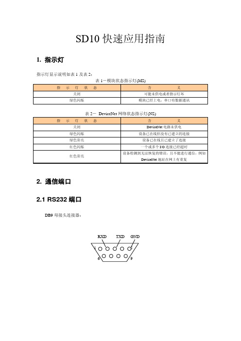
SD10快速应用指南_V13
如上图所示,其中,Scanlist 选项可以设置添加到 DeviceNet 主站扫描列表的设备,Input、 Output 分别可以设置网关映射到 DeviceNet 主站映射区的输入、输出字节数。
特别需要注意的是 Scanlist 中的 SD10 输入输出字节数必须和产品 SD10 中的输入输出字 节数一致!否则无法通信。
例如:在配置 DeviceNet 输入输出都是 32 个字节的情况下,串口发送 2 次数据给 DeviceNet 主站,SD10 就先缓存这两帧数据(即多帧缓存功能),若 DeviceNet 输出数据前 2 个字节发送 0 0(第 1,2 个字节是流量控制字节),这样 SD10 才会把第一帧数据发送给 DeviceNet,若 DeviceNet 可以开始接收第二帧数据,则 DeviceNet 输出数据的第 1,2 个字 节需改为 80 00(控制流量位反转),即第 1 个字节的最高位需进行 0,1 反转变化。
注意:一般设备只需连接 3,2,5 脚即可。
接线 连用户设备的 RXD,2 号脚 连用户设备的 TXD,3 号脚 连用户设备的 GND,5 号脚
2.2 DeviceNet 接线
五针连接器:
1
5
-24V
CANL
CANH
屏蔽
+24V
DeviceNet 侧采5脚
接线 GND CANL 屏蔽 CANH +24V
3. 软件配置
本网关的参数可通过 DeviceNet 网络参数来进行配置,用户能够在 DeviceNet 主站组态软件 中设置 SD-10 的串口及 DeviceNet 相关参数。
3.1 DeviceNet 参数配置
DNet Input bytes:DeviceNet I/O 连接输入字节数,可选 16 个字节、20 个字节、32 个 字节、48 个字节、64 个字节,默认字节为 20 个字节。
SD10-快速入门指南
4. The Customer agrees not to attempt to decompile the object code of the Product otherwise than in circumstances specifically
provided for by law, and then only after consultation with Digico UK Ltd.
SD10 操作指南
用户手册-入门指南
结合 SD 系列软件阅读参考
用户手册 B 版本对应控台 4.0.680+
地址:广州市番禺区沙头街禺山西路 363 号联邦工业城内 电话:020-84666123 传真:020-84661633 官网:
0-1
SD10 操作指南
Copyright © 2014 Digico UK Ltd
All rights reserved.
No part of this publication may be reproduced, transmitted, transcribed, stored in a retrieval system, or translated into any language in any form by any means without the written permission of Digico UK Ltd. Information in this manual is subject to change without notice, and does not represent a commitment on the part of the vendor. Digico UK Ltd shall not be liable for any loss or damage whatsoever arising from the use of information or any error contained in this manual. All repair and service of the SD10 product should be undertaken by Digico UK Ltd or its authorised agents. Digico UK Ltd cannot accept any liability whatsoever for any loss or damage caused by service, maintenance, or repair by unauthorised personnel.