TH-20温湿度自动校准系统(新)-用户手册
温湿度传感器(型号:WHT20B)使用说明书
温湿度传感器(型号:WHT20B)使用说明书版本号:1.0实施日期:2023-02-01郑州炜盛电子科技有限公司Zhengzhou Winsen Electronic Technology Co.,Ltd声明本说明书版权属郑州炜盛电子科技有限公司(以下称本公司)所有,未经书面许可,本说明书任何部分不得复制、翻译、存储于数据库或检索系统内,也不可以电子、翻拍、录音等任何手段进行传播。
感谢您使用本公司的系列产品。
为使您更好地使用本公司产品,减少因使用不当造成的产品故障,使用前请务必仔细阅读本说明书并按照所建议的使用方法进行使用。
如果您没有依照本说明书使用或擅自去除、拆解、更换传感器内部组件,本公司不承担由此造成的任何损失。
您所购买产品的颜色、款式及尺寸以实物为准。
本公司秉承科技进步的理念,不断致力于产品改进和技术创新。
因此,本公司保留任何产品改进而不预先通知的权力。
使用本说明书时,请确认其属于有效版本。
同时,本公司鼓励使用者根据其使用情况,探讨本产品更优化的使用方法。
请妥善保管本说明书,以便在您日后需要时能及时查阅并获得帮助。
郑州炜盛电子科技有限公司WHT20B温湿度传感器产品描述WHT20B温湿度传感器嵌入了适于回流焊的双列扁平无引脚SMD封装,温度和湿度信号可以在不同的引脚读出,底面3.0×3.0mm,高度1.0mm。
传感器输出经过标定的数字信号,标准I2C格式。
WHT20B温湿度传感器,包含一个全新设计的ASIC专用芯片内置晶体管Vbe温度特性,实现高精度温度检测;同时包含一个电容湿度芯片,其中湿敏材料吸湿后介电常数变化实现环境湿度检测。
并结合最新的集成电路信号处理技术而成的双芯片解决方案。
具有体积小、功耗低、可靠性高、兼容性好等优点。
产品特点⏹高精度,±3.0%RH和±0.5℃⏹宽电源电压范围,从2.0V到5.5V⏹采用SMD封装,适于回流焊⏹响应迅速、抗干扰能力强⏹高湿条件下优异的长期稳定性应用场景家电领域:家电、湿度调节、暖通空调、除湿机、智能恒温器、房间监视器;工业领域:汽车、测试及检测设备、自动控制;其他领域:数据记录器、气象站、医疗及其他相关温湿度检测控制。
IIOT-TH20 温湿度传感器说明书
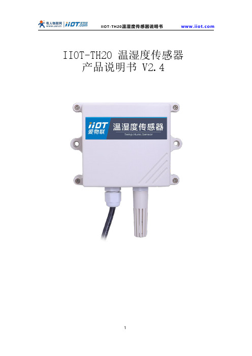
IIOT-TH20温湿度传感器产品说明书V2.4目录1.产品资料 (3)2.产品概述 (3)2.1.功能特点 (3)2.2.技术参数 (3)2.3.产品尺寸 (4)3.模拟量参数含义 (4)3.1.模拟量4-20mA电流输出 (4)4.通讯协议 (4)4.1.通讯基本参数 (4)4.2.数据帧格式定义 (5)4.3.寄存器地址 (5)4.4.通讯协议示例以及解释 (6)5.常见问题及解决办法 (8)6.安装说明 (8)7.接线说明 (9)7.1.485型接线定义 (9)7.2.模拟量型接线定义 (9)7.3.模拟量典型三线制接线方式 (10)8.联系方式 (10)9.质保与售后 (10)10.免责声明 (11)11.修订记录 (11)1.产品资料产品说明书下载地址:https:///product/444.html设备上云操作指导详情:https:///news/1204.html2.产品概述IIOT-TH20系列温湿度传感器广泛适用于农业大棚/花卉培养等需要温湿度监测的场合。
传感器内输入电源,感应探头,信号输出三部分完全隔离。
安全可靠,外观美观,安装方便。
2.1.功能特点●探头灵敏度高,信号稳定;●测量范围宽、线形度好、精度高;●防水性能好、安装使用方便。
2.2.技术参数参数技术指标产品名称温湿度传感器产品供电DC9V-24V产品功耗≤10mA/DC12V数据刷新时间<1S运行环境工作温度:-20-80℃工作湿度:0-95%RH(无结露)量程温度:-40-80℃;湿度:0-100%RH 精度湿度:±3%RH;温度:±0.5℃长期稳定性湿度:≤1%/y;温度:≤0.1℃/y输出方式RS485接口,Modbus-RTU通讯协议4-20mA接口,电流信号模拟量负载能力电流输出,≤600欧姆尺寸规格110*85*44mm,壁挂式王字壳IP防护等级IP65默认线缆长度 1.2米,线缆长度可按要求定制2.3.产品尺寸3.模拟量参数含义3.1.模拟量4-20mA电流输出电流值温度湿度4mA-40℃0%20mA80℃100%温度计算公式为:P=(I/1000-4mA)*7.5-40℃;湿度计算公式为P=(I/1000-4mA)*6.25%RH;其中I的单位为mA。
TH系列触摸屏用户手册
1 TH 系列触摸屏产品概述 .......................................................................................................................... 1 1-1. 性能特点 .............................................................................................................................................. 1 1-2. 工作流程 .............................................................................................................................................. 2
TH-20温湿度巡检仪使用说明书
测量项目 温度 湿度
传感器类型 热电阻(4W) 热电偶(K) 湿度传感器
测量范围 (-90~310)℃ (50~1280) ℃ (0~100)%RH
分辨率 0.01℃ 0.1℃ 0.01%RH
准确度 ±0.10℃ ±1.0℃ ±0.1%RH
二、 硬件系统介绍
1. 仪器面板介绍
仪器正面板如右图所示:
液晶显示区
U盘保存时间间隔(1~29)秒03
︽︽︽︽︽︽︽︽︽︽︽︽︽︽︽
∧ ∨ 修改
确认-设定
通过“▲、▼”按钮,增加或者减少时间间隔,按“确认”保存退出。 b、设置日期、时间
第 7 页 共 21 页
TH-20 温湿度自动校准系统用户手册
设置时间、日期 ︾︾︾︾︾︾︾︾︾︾︾︾︾︾︾
日期:10年 07月 19日 时间:16时 07分 19秒
∧ ∨ 翻页
确认-切换
a、 此时按“▲、▼”按钮,显示其余通道的数值,如下图所示:
TH-20 温湿度校准系统
︾︾︾︾︾︾︾︾︾︾︾︾︾︾︾
⒀ 500.2 ⒁ 501.3 ⒂ 502.6
⒃ 500.6
A) 83.21 B) 82.19 C) 84.53
D) 84.23
︽︽︽︽︽︽︽︽︽︽︽︽︽︽︽
∧ ∨ 翻页
第 13 页 共 21 页
TH-20 温湿度自动校准系统用户手册
在右侧的三维图形中会自动显示所选布局方案的布点位置图。也可以通过在右侧的三 维图形的方框内手动输入通道号,完成布点。在确认测点布局后,若要保存布局,则在下 拉框中输入方案名,点击【保存】按钮保存当前布局方案。点击【确定】按钮后,工具栏 上的数据采集按钮 将有效,表示可以开始进行数据采集。如下图:
吉永(YOSHINAGA)TP20系列数字温度调节器使用说明书
请注 意:本 书的 内 容将 来 若有 变 更,恕不 另 行通 知,敬 请谅 解。
2 ).输 入 种 类 和 测 量 范 围 设 定
▪ 多 输入时,测 量范围 上下限 值为 设定传 感器测 量范 围上下 限值,且不 可修改 。 ▪ 电 压或电 流输入 时,测量范 围上 下限值 可以设 定,测 量范 围上 下限值 修改将 初始 化所有 与 量程有 关的 数据。 ▪ 仅 复位状 态可改 变输 入类型 。 输入种 类及 测量范 围请参 见表 一:输 入类 型和测 量范围 一览 表 注意:重新 设定输 入类 型,将 初始 化与量 程有关 的参 数。 3 ) . P ID参 数 设 定 ▪ P (比 例带) 通过比 例带进 行没 有振荡 的平滑 控制,如果 比例 带太小,调节 波动 且调节 结果类 似ON - O FF 作用。 ▪ I (积 分时间 ) 通过积 分时 间纠正 比例带 产生 的偏差,积 分时间 越长,纠正 作用越 弱,积 分时 间越 短,纠 正 作用越 强。 ▪ D (微 分时间 ) 通过微 分时 间防止 超调,微分 时间越 长,微 分作 用越 强,但控制 结果可 能波 动。 ▪ M R (积分 偏移 量) PI D作用 中的积 分时间 I自 动纠正 偏差,但如 果I设置为 OF F时,将不纠 正偏 差。此 时,可以手 动 设置积 分偏 移量来 纠正偏 差。 ▪ I H (超调 抑制 系数) 通过 超调抑 制系数 纠正P I D控制时 的欠调 与超 调,系 数越 大抑 制作用 越强 。 4 ).目 标 设 定 值 的 限 制 ▪ 用 于在测 量范围 内,进一步 限制 用户的 设定范 围。 例 如: K型 热电偶 测量 范围0~8 0 0. 0℃,而 工艺 要求为10 0 . 0~60 0 . 0℃,通过 目标 设定值 限制 避 免S V值 设置 错误。 5 ).调 节 输 出 值 限 幅 设 定 ▪ 本 系列温 度调节 器提 供了3组P I D参 数,可 分别 设置其 输出下 限值( 0 . 0~99 . 9 %)和 输 出上限 值( 0. 1~1 0 0. 0 % ),下限 值小于 上限 值。 例如:对于0~1 0 V的 输出 范围内 ,O U T1下限 值设置 为2 0 %, O U T1上限 值设置 为8 0 %,则输 出 范围 为2~8V 6 ).调 节 输 出 比 例 周 期 ▪ 初 始值: S S R驱 动电压 输出 时为3秒 。 继 电器输 出时为30秒。 ▪ 周 期短调 节变化 快,适合小 惯性 系统,惯 性 大的周 期可设 定长 些。 7 ).调 节 输 出 正 作 用(D A) /反 作 用(R A) ▪ 正 作用: P V测 量值与SV设 定 值的 正偏差 越大,调节 输出越 大。 ▪ 反 作用: P V测 量值与SV设 定 值的 正偏差 越大,调节 输出越 小。 ▪ 单 输出时: 温 度调节 器的 输出特 性可设 置为: R A (加 热) , D A(冷却) 。 ▪ 双 输出时:( O U T2为选 件) O U T 1和O U T 2的 输出特 性可 分别设 置为: R A (加 热) , D A(冷却)。 用 户可根 据现 场需要 自由设 置O U T1和O U T2的输 出特 性。
2012版 用户手册 温湿度试验设备自动检定系统 V2012.12
“Vtest-1101温湿度试验设备自动检定系统”是由福建省计量科学研究院长期从事热工计量测试的高级工程师根据国家校准规范《JJF 1101-2003环境试验设备温度、湿度校准规范》、GB/T5170系列国家标准研究开发的一套自动检定系统。
其主要用于恒温恒湿箱(房)、高低温试验箱,老化试验箱,干燥箱,培养箱,水泥养护箱(室),盐雾腐蚀试验箱,恒温水/油槽,冰箱、冷藏库,箱式电阻炉,高温定炭炉……等温湿度试验设备的温湿度参数的检定或校准。同时,在电子行业可使用于电路板温升试验、环境试验设备温湿度参数监控记录,在医药行业可用于GMP认证对检验过程的温度、湿度监控、记录、报表。是计量、质检、医药、电子等行业实现温湿度参数校准、测量、监控、记录的理想选择,可以用于几乎所有和温度、湿度两个参数相关的计量器具或仪器设备的检测校准。
说明:
"USB Serial Port (com5)"内置USB转串口模拟的串口的端口号是5;
如果想修改串口号:则双击此项目——>点击"端口设置"——>点击"高级"——>将端口号中的端口改为需要的端口号,比如com4。
B转串口所产生的串口号是多少,通常和插入哪个USB口有关,最好固定使用一个USB口给系统供电、通讯,这样就不要经常设置自动检定系统中的端口了。
系统软件具有满足医药行业GMP认证要求的数据记录、处理、报表存档功能。
硬件系统由专业的智能仪表厂家生产,实现规模化、专业化,保证了产品质量。硬件系统具有超强的自校功能。1.采集器提供零位、比例的修正功能。2.自动检定系统软件具有自动校准功能,及其方便的调用、计算当前的修正值,满足精密检测要求。
系统软件提供4个通道(可根据用户要求扩展相对湿度测量通道数量)的干湿球法测量相对湿度,通过对风速、气压等参数的修正,准确测量相对湿度。
THS系列智能温湿度控制仪使用说明
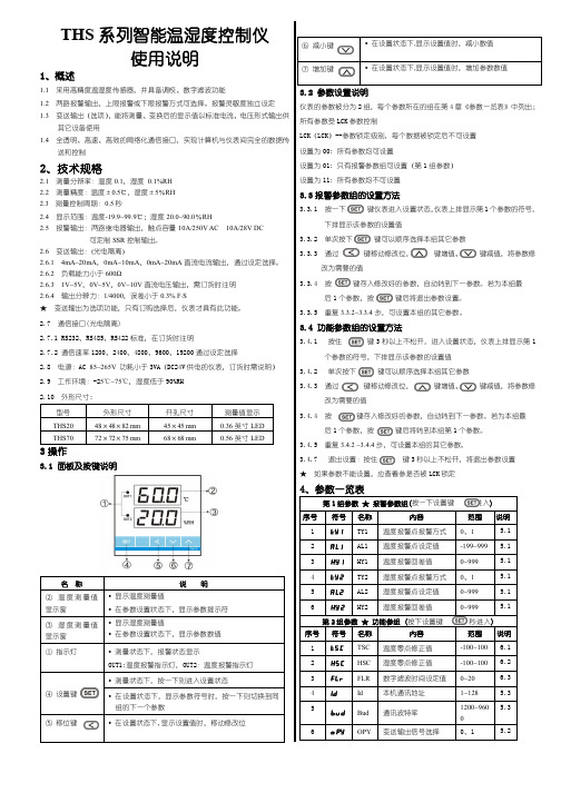
THS 系列智能温湿度控制仪使用说明1、概述1.1 采用高精度温湿度传感器,并具备调校、数字滤波功能1.2 两路报警输出,上限报警或下限报警方式可选择。
报警灵敏度独立设定 1.3 变送输出(选项),能将测量、变换后的显示值以标准电流、电压形式输出供其它设备使用1.4 全透明、高速、高效的网络化通信接口,实现计算机与仪表间完全的数据传送和控制2、技术规格2.1 测量分辩率:温度0.1,湿度 0.1%RH 2.2 测量精度:温度±0.5℃,湿度±5%RH 2.3 测量控制周期:0.5秒2.4 显示范围:温度-19.9~99.9℃;湿度20.0~90.0%RH2.5 报警输出:两路继电器输出,触点容量10A/250V AC 10A/28V DC 可定制SSR 控制输出。
2.6 变送输出:(光电隔离)2.6.1 4mA~20mA ,0mA~10mA ,0mA~20mA 直流电流输出,通过设定选择。
2.6.2 负载能力小于600Ω2.6.3 1V~5V ,0V~5V ,0V~10V 直流电压输出,需订货时注明 2.6.4 输出分辨力:1/4000,误差小于0.3% F .S★ 变送输出为选项功能,只有订购选择后,仪表才具有此功能。
2.7 通信接口(光电隔离)2.7.1 RS232、RS485、RS422标准,在订货时注明2.7.2 通信速率1200、2400、4800、9600、19200通过设定选择2.8 电源:AC 85~265V 功耗小于3VA(DC24V 供电的仪表,订货时需说明) 2.9 工作环境:-25~℃75℃,湿度低于90%RH 2.10 外形尺寸:型号 外形尺寸 开孔尺寸 测量值显示 THS20 48×48×82 mm 45×45 mm 0.36英寸LED THS7072×72×75 mm68×68 mm0.56英寸LED3操作3.1 面板及按键说明名 称 说 明② 温度测量值显示窗 • 显示温度测量值• 在参数设置状态下,显示参数提示符 ③ 湿度测量值显示窗 • 显示湿度测量值• 在参数设置状态下,显示参数数值 ① 指示灯• 测量状态下,报警状态显示OUT1:温度报警指示灯,OUT2:温度报警指示灯④ 设置键• 测量状态下,按一下则进入设置状态• 在设置状态下,显示参数符号时,按一下则切换到同组的下一个参数⑤ 移位键• 在设置状态下,显示设置值时,移动修改位3.2 参数设置说明仪表的参数被分为2组,每个参数所在的组在第4章《参数一览表》中列出; 所有参数受LCK 参数控制LCK(LCK)--参数锁定级别, 每个数据被锁定后不可设置 设置为00: 所有参数均可设置设置为01: 只有报警参数组可设置(第1组参数)设置为11: 所有参数均不可设置3.3报警参数组的设置方法3.3.1 按一下 键仪表进入设置状态,仪表上排显示第1个参数的符号,下排显示该参数的设置值3.3.2 单次按下 键可以顺序选择本组其它参数3.3.3 通过 键移动修改位, 键增值、 键减值,将参数修改为需要的值3.3.4 按 键存入修改好的参数,自动转到下一参数。
智能温湿度测控器使用说明书
ConsenwellV1.1尊敬的用户:衷心感谢您选用Consenwell 康森韦尔的产品。
本手册主要介绍智能温湿度测控器的工作原理、技术指标、主要功能、安装调试及使用与维护等内容。
为了使您更好地使用我们的产品,请您仔细阅读本手册,在应用中如果您有任何问题和要求,或需要相关技术支持,可以与我们的销售单位联系,我们将及时给予回应。
目录 1.前言 --------------------------------------- 错误!未定义书签。
2.内容 --------------------------------------- 错误!未定义书签。
3.要求 --------------------------------------- 错误!未定义书签。
使用说明书智能温湿度测控器 S200HTT4.警示 --------------------------------------- 错误!未定义书签。
5.概述 --------------------------------------- 错误!未定义书签。
6.技术参数----------------------------------- 错误!未定义书签。
7.产品外观和结构---------------------------- 错误!未定义书签。
8.指示灯和按键功能说明 --------------------- 错误!未定义书签。
9.产品接线端子定义-------------------------- 错误!未定义书签。
10.产品原理和功能-------------------------- 错误!未定义书签。
11. 通讯接口 -------------------------------- 错误!未定义书签。
通讯数据项说明 ------------------------------ 错误!未定义书签。
无-------------------------------------------- 错误!未定义书签。
国电南瑞TH9310 20 系列仪器用户手册说明书
V2.2目录第1章安装使用 _________________________________________________ 1-11.1使用注意事项___________________________________________________________________ 1-11.2移动时的注意要点________________________________________________________________ 1-11.3连接交流电源线__________________________________________________________________ 1-21.4接地___________________________________________________________________________ 1-21.5操作检查_______________________________________________________________________ 1-31.6仪器的其它特性__________________________________________________________________ 1-3 第2章操作规范和措施 ___________________________________________ 2-12.1禁止的操作行为__________________________________________________________________ 2-12.2紧急情况的处理__________________________________________________________________ 2-12.3测试中的预防措施________________________________________________________________ 2-12.4高压测试警告___________________________________________________________________ 2-22.5有故障仪器的危险状态处理________________________________________________________ 2-32.6保证长时间无故障使用的条件______________________________________________________ 2-32.7日常检查_______________________________________________________________________ 2-3 第3章仪器面板概述 _____________________________________________ 3-13.1前面板说明_____________________________________________________________________ 3-13.1.1电源开关(POWER) _____________________________________________ 3-13.1.2 START键、STOP键 ___________________________________________ 3-13.1.3商标及型号___________________________________________________ 3-13.1.4 USB接口 ____________________________________________________ 3-13.1.5指示灯区域___________________________________________________ 3-13.1.6功能区域(FUNCTION) _______________________________________ 3-13.1.7 HV __________________________________________________________ 3-23.1.8输出电压高端(HV) __________________________________________ 3-23.1.9测试低端、测试电流返回端(LOW /RET) ___________________________ 3-23.1.10移动键______________________________________________________ 3-23.1.11快捷功能键 __________________________________________________ 3-23.1.12 COPY键 ____________________________________________________ 3-23.1.13 LCD液晶显示屏 _____________________________________________ 3-23.2后面板说明_____________________________________________________________________ 3-33.2.1功放风扇散热口_______________________________________________ 3-33.2.2测试低端、测试电流返回端(选件) _____________________________ 3-33.2.3高压输出端(选件)___________________________________________ 3-33.2.4电源插座:自带保险丝盒,可切换线电压模式。
AHT20 温湿度传感器说明书
AHT20说明书温湿度传感器●完全标定●高性价比●数字输出,I2C接口●优异的长期稳定性●响应迅速、抗干扰能力强●宽电压支持2.2-5.5VDC产品简述AHT20温湿度传感器嵌入了适于回流焊的双列扁平无引脚SMD封装,传感器输出经过标定的数字信号,标准I2C格式。
AHT20配有ASIC专用芯片、MEMS半导体电容式湿度传感元件和片上温度传感元件,使其性能大大提升,每一个传感器都经过校准和测试,并印有产品批号。
应用范围广泛应用于智能家居、消费电子、医疗、汽车、工业、气象等领域,例如:暖通空调、除湿器和冰箱等家电产品,测试和检测设备及其他相关温湿度检测产品。
图1.AHT20传感器封装图(单位:mm公差:±0.2mm)传感器性能相对湿度表1.湿度特性表参数条件最小典型最大单位分辨率典型-0.024-%RH 精度误差1典型-±2-%RH 最大见图2-%RH 重复性--±0.1-%RH 迟滞--±1-%RH 非线性--<0.1-%RH 响应时间2τ63%-<8-s 工作范围扩展30-100%RH 年漂移4正常-<1-%RH/yr图2.25℃时相对湿度的典型误差和最大误差电气特性表2.电气特性参数条件最小典型最大单位供电电压典型 2.2 3.3 5.5V 供电电流,IDD5休眠--250nA 测量-980-µA 功耗5休眠--0.8µW 测量- 3.2-mW通讯两线数字接口,标准I 2C 协议1此精度为出厂检验时,传感器在25℃供电电压为3.3V 条件下的测试精度。
此数值不包括迟滞和非线性,并只适用于非冷凝条件。
225℃和1m/s 气流条件下,达到一阶响应63%所需时间。
3超出8~85%RH 范围,传感器读数偏差请参阅用户指南1.1。
4如果传感器周围有挥发性溶剂、带刺激性气味的胶带、粘合剂以及包装材料,读数可能会偏移。
详细说明请参阅“用户指南”。
土壤型温湿度传感器说明书 (详细)
土壤型温湿度传感器说明书_ 相对湿度和温度测量_ 兼有露点_ 全部校准,数字输出,_ 卓越的长期稳定性_ 防水封装,可用于土壤测量_ 超低能耗产品概述数字温湿度传感器系列中土壤型专用传感器,它把传感元件和信号处理集成起来,输出全标定的数字信号。
产品具有极高的可靠性与卓越的长期稳定性。
传感器包括一个电容性聚合体测湿敏感元件、一个用能隙材料制成的测温元件,并在同一芯片上,与14 位的A/D 转换器以及串行接口电路实现无缝连接。
因此,该产品具有品质卓越、超快响应、抗干扰能力强、极高的性价比等优点。
每个传感器芯片都在极为精确的湿度腔室中进行标定,校准系数以程序形式储存在OTP 内存中,在标定的过程中使用。
传感器在检测信号的处理过程中要调用这些校准系数。
两线制的串行接口与内部的电压调整,使外围系统集成变得快速而简单。
微小的体积极低的功耗,使SS2005成为各类应用的首选。
土壤专用传感器提供4 脚引线封装,且传感器与引线之间采用接插件形式,易于更换与替换。
接口说明:技术参数:传感器外形尺寸:SHT系列传感器性能说明图 2 25℃时传感器的最大相对湿度误差图3 最大温度误差电气特性:1 默认测量分辨率为温度14 位,湿度12 位。
通过状态寄存器可分别降至12 位和8 位2 在出厂质量检验时,每支传感器都在25℃(77℉)和3.3V 条件下测试并且完全符合精度指标。
该精度值不包括滞后与非线性。
3 在25℃和1m/s 气流的条件下,达到一阶响应63%所需要的时间。
4 在挥发性有机混合物中数值可能会高一些。
见说明书1.3。
5 在VDD=5.5V 和25℃的条件下,每秒进行一次12 位精度测量的平均值。
6 响应时间取决于传感器表面的热容和热阻。
使用指南1. 应用信息1.1 工作条件传感器在建议的工作条件下性能正常,请参阅图4。
超出建议的工作范围可能导致信号暂时性漂移(60 小时后漂移+3%RH)。
当恢复到正常工作条件后,传感器会缓慢自恢复到校正状态。
SHT20最新数字温湿度传感器芯片 程序
/***********主程序***********/
void main()
{
uint T,RH,B1;
//i=RH_Result();
//i=T_Result();
SHT2x_init();
SHT2x_Resolution();
B1=SHT2x_user_register();
getACK();
send(T_code);
getACK();
start();
send(add_r);
getACK();
delay85ms();
T_Data=Read();
/*3**********传感器测量分辨率设置*******/
/*4**********传感器低电压检测***********/
// 1传感器初始化&软复位
void SHT2x_init()
{
start();
send(add_w);
getACK();
send(RST_code);
send(user_code_r);
getACK();
start();
send(add_r);
getACK();
register_data=Read();
noACK();
stop();
return register_data;
}
// 3 传感器测量分辨率设置
// 测量分辨率设置 RH 8 BIT、T 12 BIT,测量时间RH4ms、T22ms
#define user_code_r 0xe7 //用户寄存器 读指令,可读电池电压是否小于2.25V。(测量后才可查看)
自动温湿度操作说明
温湿度操作和常见问题1、如何查看实时的温湿度记录:a.进入自动温湿度界面后,点连接---设置操作内容----读实时数据2、如何设置存储时间(多长时间存储一次)在设置操作内容中,左上角有个存储间隔设置成多少秒保存一次,如果不设置,系统默契认是300秒即五分钟保存一次。
3、如果保存数据到服务器A、点设置操作内容中的读历史数据,系统自动将存在控制器中的数据存到服务器上,直到系统显示读取历史数据结束。
B、读取历史数据结束后,一定要点一下数据复位按钮,否则以后再点读历史数据时,仍会把这次的数据读到数据库中,同时,如果没点数据复位按钮,控制器中的数据一但溢满,就不再保存新的数据。
(平时不开电脑的状态下,自动温湿度记录仪会自身把数据存在控制器中,要把控制器中的数据存到服务器中时,点读历史数据操作台)4、平时如何查看历史数据在连接状态下,选择好时间段,选择好模式(温度、湿度)点提取服务器数据按钮,就可以把以前存在服务器中的温湿度记当调出来!图1-15、数据超标后如何调整在设置操作内容中有个处理设置,前面可以选择1-16是8个探头所对应的温度和湿度,对应关系如图1-1所示。
处理设置后的两个文本框,前一个输你要调的探头的温度或湿度,如我要调七号探头的温度则输13,如果我要向下调5度,则在后面的的文本框中输5,如果是向上调5度,刚输—5。
输完后点处理设置下面的确定按钮!最后一个下拉列框显示《B》设置成功,请重新复位设备,证明调试完成,如果显示系统出错,重新连控制器后操作以上步骤。
注:每次调整数据都是在正确数据的基础上调整的,如现在探头是21度,已经向下调5度后,点实时数据看到的是16度,如果此时你想再向下降一度,如果直接在处理设置后输1,刚探头会变成2度,而不是你想要的15度。
6、时间久了以后,忘了以前所调的温度,想要恢复正确数据时如保操作点设置操作内容,点设置复位按钮。
(每次检查前要点数据复位按钮,保证数据是正常的读数,否则与检查组的所带设备的数据不一致,不能通过检查.)7、连接不上提示119错误:119错误造成的情况:1、网络不通2、同个局域网有别的人在操作3、刚点过断开按钮,由于控制器是工业型的,需要10-15秒的缓冲,等15秒后再连就可以,或把整个系统退出,重新进入系统再点连接。
TH系列触摸屏用户手册
4 接口及开关说明 ........................................................................................................................................ 12 4-1.信捷 TH 系列触摸屏接口说明 ......................................................................................................... 12
简体繁体英文日文韩文等多种语言字符尺寸任意字体任意大小触摸面板4线电阻式触摸存储画面8mb器冷却方式自然风冷结构外部尺寸15001000410面板开孔尺寸144094032th765m项目th765m输入电压dc20dc28v电气消耗电流250ma允许瞬时停电小于10ms特征耐电压ac1000v10ma1分钟信号与时间绝缘阻抗dc500v约10m信号与时间com1接口支持rs232rs485com2接口支持rs232rs422rs485接口usb1接口usba符合usb20规范usb2接口usba符合usb20规范usb3接口usbb符合usb20规范操作温度050保存温度2060环境湿度2085无凝露环境耐振动1025hzxyz方向各30分钟2g抗干扰电压噪声
RHT20 温湿度记录仪使用说明书
User's GuideHumidity & Temperature DataloggerModel RHT20RHT20 V1.0 8/092IntroductionCongratulations on your purchase of this Temperature and Humiditydatalogger. With this meter, you can monitor and log data over long periodsof time and then easily transfer the data to a pc for viewing and evaluation.The LCD display provides current or Max/Min temperature, humidity and time information. This meter is shipped fully tested and calibrated and, with proper use, will provide years of reliable service.Description1 Record LED2 Alarm LED3 LCD Display4 Temperature – Humidity display selection5 MAX/MIN display selection6 Battery Compartment (rear)7 Temperature and Humidity sensors8 USB PC port (bottom)Display DescriptionFull battery symbol.Weak battery symbol. Replacebattery when this appears.Battery life is more than 3months.DATE: Current date is displayedTIME : Current time is displayedTime and Date automaticallyswap every 10 sec.MAX : Maximum value duringadatalogging session isdisplayedMIN: Minimum value during a datalogging session is displayedREC : Recording in progress indicatorFULL: Memory is full indicator%RH : Humidity value is displayed°C: Celsius temperature units°F: Fahrenheit temperature unitsOperation:The display and front panel buttons provide a means to view the status of the datalogger, observe the current Temperature or Relative Humidity and to view the MAX and MIN values recorded during a recording session. The datalogger setup conditions such as sample rate, temperature units and alarm values are programmed via the provided software. Refer to the software Help File on the disk for those procedures.1. Press the MAX/MIN button to view the recorded Max and Min values withthe time they were recorded. If, while in this mode, no button is pressedfor 40 seconds the display will automatically return to the real time display.2. The Time and Date display will automatically toggle every 10 seconds3. When downloading the data to the PC, “-PC-” will be displayed on theLCD. After the download is complete, the datalogger will display the lastvalue recorded, but it will stop recording. The logger needs to be re-setfrom the software to begin a new recording session.4. The “REC” LED will flash at the programmed rate when the unit isdatalogging.5. Alarm function: When the measured value exceeds the programmedupper or lower limit and the LED function is selected in the software, theALM LED will flash one time per minute.6. If “-LO-“ is displayed, the temperature and humidity sensors needattention.7. The datalogger should be placed upright when in use.8. If used in low temperature, high humidity environment, the dataloggershould be placed upright in a dry area to remove any condensation before downloading the data.9. Battery life can be extended by leaving the datalogger connected to a pc.10. Disabling the REC and ALM LED’s will extend battery life.RHT20 V1.0 8/093Combination LockThe logger is supplied with a wall mount case and security Array combination lock. The lock is shipped with a -0-0-0- code asviewed from the side with the alignment bar. To change thecode:1 Press the release to open the lock (1)2 Using a pointed object, press IN and HOLD the lockingpin on the bottom of the lock (2).3 Set the new code (3) and release the locking pinWarrantyEXTECH INSTRUMENTS CORPORATION (A FLIR COMPANY) warrants this instrument to be free of defects in parts and workmanship for one year from date of shipment (a six month limited warranty applies to sensors and cables).If it should become necessary to return the instrument for service during orbeyond the warranty period, contact the Customer Service Department at (781) 890-7440 ext. 210 for authorization or visit our website for contact information. A Return Authorization (RA) number must be issued before any product is returned to Extech. The sender is responsible for shipping charges, freight, insurance and proper packaging to prevent damage in transit.This warranty does not apply to defects resulting from action of the user suchas misuse, improper wiring, operation outside of specification, improper maintenance or repair, or unauthorized modification. Extech specifically disclaims any implied warranties or merchantability or fitness for a specific purpose and will not be liable for any direct, indirect, incidental or consequential damages. Extech's total liability is limited to repair or replacement of the product. The warranty set forth above is inclusive and no other warranty,whether written or oral, is expressed or implied.RHT20 V1.0 8/094RHT20 V1.0 8/09 5Support line (781) 890-7440TechnicalSupport:Extension200;E-mail:******************Repair&Returns:Extension210;E-mail:*****************Product specifications subject to change without noticeFor the latest version of this User Guide, Software updates, and otherup-to-the-minute product information, visit our website: Extech Instruments Corporation, 285 Bear Hill Road, Waltham, MA 02451 Software Installation1.Place the CD in the drive and then follow the on-screen installation instruction. 2.After the software is installed, keep the CD in the drive and connect the datalogger to the PC by the USB cable. 3. A USB Driver installation window will pop-up. Follow the directions toinstall the driver.Software applicationThe Datalogger USB software is a program for collecting data from the DATA LOGGER when it is connected to a PC or notebook computer. The data may be displayed graphically, as Excel or similar programs. The major functions are all listed in the main window.System RequirementsWindows 2000 or Windows XP or VistaMinimum Hardware Requirements:PC or NoteBook with Pentium 90MHz or higher, 32 MB RAM ;At least 7 MB byte hard disk space available to install HT Datalogger USBsoftware.Recommended display resolution 1024X768 with High Color(16 bit).Software OperationThe Software operation is described in the HELP file .Calibration and Repair ServicesExtech offers repair and calibration services for the products we sell.Extech also provides NIST certification for most products. Call the Customer Care Department for information on calibration services available for thisproduct. Extech recommends that annual calibrations be performed to verify meter performance and accuracy.SpecificationsLCD Display Multi-functionMeasurement ranges 0 to 100% RH-40 to 158°F, -40 to 70°C0.1RHResolution 0.1°,Maximum data points 16,350 Temperature and 16,350Humidity valuesSample rate 1s to 24h selectableAnalysis software 2000/XP/ VistaOpen input indication "LO" appears on the LCDLow battery indication Empty battery symbol appears on the LCDPower supply 3.6V Lithium BatteryBattery life 3 months (approximately)Operating Temperature -40 to 158°F, -40 to 70°COperating Humidity 0 to 100% RHLCD Operating Temperature -13°F to 158°F (-25°C to 70°C)(94.4x48.9x31.2mm)Dimensions 3.7x1.9x1.2"(90.7g)Weight 3.2oz.Range Accuracy Relative Humidity 0 to 20% and 80 to 100% ±5.0%20 to 40% and 60 to 80% ±3.5%40 to 60% ±3.0%Temperature -40 to 14°F and 104 to 158°F ±3.6°F14 to 104°F ±1.8°F-40 to -10°C and 40 to 70°C ±2°C-10 to 40°C ±1°CCopyright © 2009 Extech Instruments Corporation (a FLIR company)All rights reserved including the right of reproduction in whole or in part in any form.RHT20 V1.0 8/096。
AQH-20 indoor air quality meter操作指南说明书
measurement is shown in top displayAir temperature, dew point, or wet bulb temperature is shown in lower left display Humidity measurement is shown in lower right displaySPECIFICATIONSMeasurement Ranges:CO 2: 0 to 2000 ppm.Temperature: 14 to 140°F (-10 to 60°C).Relative Humidity: 0.0 to 99.9% RH.Accuracy:CO 2: ±30 ppm ±5% of reading;Temperature: ±0.9°F (±0.6°C);Humidity: ±3% RH (10 to 90%), ±5% (0.0 to 9.9% or 90 to 99.9%).Resolution:CO 2: 1 ppm;Temperature: 0.1°F (0.1°C);Humidity: 0.1% RH.Response Time:CO 2: < 30 seconds;Temperature: < 2 minutes;Humidity: <10 minutes.Display: Four digits for temperature/CO 2and 3 digits for humidity.CO 2Sensor: Non-dispersive infrared.Operating Temperature:32 to 122°F (0 to 50°C).Operating Humidity (Non-Condensing):0 to 95% RH.Power Requirements:(4) 1.5 V AA alkaline batteries, included, user replaceable.Warm Up Time: 30 seconds.Weight: 6.76 oz (200 g).Agency Approval: CE.return to the main menu or press button to return to main menu without saving the changes.If the alarm sounds, simply press any key (but power key) to silence the alarm.Changing Engineering UnitsHold down for more than one second during normal mode to reach the main menu.Press the or the to toggle between alarm setup and unit setup.enter engineering unit setup.The current temperature unit will be blinking on the lower left of the display. Press the or the to toggle between Celsius and Fahrenheit.menu or press button to return to the main menu without saving the changes.Holding the Current ValuePress and release the to freeze the primary temperature display. “HOLD”will appear at the top left of the screen.In order to return to normal operation, press the button again and the “HOLD”icon disappears from the display.To exit, until none of the four mentioned functions appear on the screen.MIN and MAX readings show the minimum and maximum CO 2readings on the main display, respectively. STEL and TWA readings show the weighted average of the CO 2readings on the main display. STEL uses all the CO 2readings from the past 15 minutes to calculate the average. TWA uses all the readings from the past 8 hours to calculate the average. The current temperature and humidity continues to be displayed at the bottom of the LCD.Automatic Power Off (Sleep Mode)The instrument will shut off automatically after 20 minutes of operation to conserve battery life if no button is pressed. To disable the sleep mode, press “Ø set” and the “HOLD” buttons simultaneously before power on. An “n” icon will appear in the center of the display once disabled.BATTERY REPLACEMENTWhen “Lob” appears on the LCD and a beeper sounds, the batteries must be replaced.To Replace the Battery:1. Make sure the unit is powered off.2. Lay face down on a clean, flat surface.3. Open battery compartment by pushing in tab and lifting cover.4. Replace battery, taking note of the indicated polarity.5. Replace the cover.CO 2CalibrationThe CO 2sensor should be calibrated in fresh outdoor air that is well ventilated and in good weather conditions. Do not calibrate in areas with high CO 2concentrations such as crowded areas.Procedure:1. Place meter in the calibration site.2. Turn the unit on and hold down and simultaneously to enter CO 2calibration mode.3. “400ppm” and “CAL” should be blinking on the display.4. Wait 10 minutes until the blinking stops and the unit returns to normal mode.To abort the calibration, turn the meter off at any time.RH CalibrationThe RH must be calibrated with the default calibration salt. If not done properly and with the correct salts, it will cause permanent damage.33% Calibration Procedure:1. Plug sensor probe into 33% salt bottle.2. Hold down and under normal mode to enter 33% calibration.3. “CAL” and the calibrating value should be blinking on the LCD with current temperature displayed but not blinking.4. Wait about 60 minutes until “CAL” and the calibrating value stop blinking.75% Calibration Procedure:3. “CAL” value should be blinking on the LCD with current temperature displayed but not blinking.4. Wait about 60 minutes until “CAL” and the calibrating value stop blinking and the meter returns to normal mode.Users can also calibrate either calibration point individually. For the 33% calibrationpoint, press the once the 33% calibration is complete. For the 75%calibration point, press the or within the first five minutes while initializing the 33% calibration.MAINTENANCEA periodic check of the system calibration is recommended. Model AQH-20 is not field serviceable and should be returned if repair is needed (field repair should not be attempted and may void warranty). Be sure to include a brief description of the problem plus any relevant application notes. Contact customer service to receive a return goods authorization number before shipping.©Copyright 2013 Dwyer Instruments, Inc.Printed in U.S.A. 8/13FR# R6-443744-00 Rev.2CAL EscCALEscCALEsc DP/WBT MODE DP/WBT CAL EscMODE HOLDCAL EscHOLD The RH calibration should be done at 25ºC and humidity close to the calibration salt being used (must at least be stable).Model AQH-20 requires at least 5 minutes worth of values in order to calculate either of the CO 2averages.If the unit fails to power on, it is likely that the batteries also need to be replaced.Failing to turn the handheld off may result in malfunction of the unit. Dispose of used batteries promptly and keep away fromchildren.。
HC-T020-EWF系列恒温器用户指南说明书
HC-T020-EWF Series ThermostatUser GuideFor Water Heoting/Boiler/Electric HeatingWELCOMEThank you for your purchase.Your new thermostat will provide uniform and comfortable temperature controlthroughout every room in your property. We bring together technology,craftsmanship and the highest quality materials to provide you with a safereliable product combined with sleek contemporary design.Please read this installation/programming manual for comprehensiveinstructions on installing and operating your thermostat. Please also ensure asuitably qualified person installs your thermostat and complies with all localregulations.IN THE BOX YOU WILL FINDThermostat 1 pcUser Guide 1 pcFloor sensor 1 pcABOUT YOUR THERMOSTATSScrewsQC Passed2 pcs1 pcThe HC-020-WIFI series range has been developed to control electric underfloor,water heating or water/gas boiler systems. These units are designed for use incommercial, industrial, civil and domestic properties.FEATURESOn Appearance1. convenient operation creates convenient life.2. Fashion design blends in with any decor.3. Touch Screen display with backlight is easy to read, even in the dark.4. Bright buttons always remind you the world truely exist.s. Easy UI interface could be used even by child.6. Optionals of black and white housing.On Functionality1. Remote control by eWeLink App.2. O.S°C Accuracy keeps temperature within the level you set.3. Data memory when power is off.4. 7 days individual programming maximize comfort and economy.5. Create thermostat group to Centralized control6. Integrated with Amazon Alexa, Google Assistant, etc.7. All setting languages synchronize your time zone, address and language.8. No limit to add rooms and support Smart Scene.WI-Fl CONNECTION1.Scan the QR code to download " eWeLink " App, or you can also searchkeyword "eWelink" at App Store or Google play to download App.2.Open " eWelink", log in or register your account with your mobile number.Type in the verification code sent to your mobile, then set your login password.Log in--3. Note: The thermostat support two paring modes, you can choose accordingto the actual situation.EZ pairing mode: EZ mode allows for rapid networking, with high performancerequirements for Wi-Fi signal strength, routers, mobile phones or managementdevices, as shown below.After turning off the thermostat, press and hold the" 1'" button for 10 seconds,when the• icon fast flash, that stand for the device enter into paring mode.Then open eWeLink app, click "Add advice" to add devices, choose "quickpairing", select "Add one device", then choose the suitable Wi-Fi network andenter the password, click "next", then the thermostat will enter automaticconnection state, complete the Wi-Fi connection of the thermostat.MODEL DEFINITIONGA: Water heating, SAGC: Water/Gas Boiler, SAP: Weekly ProgrammableGB: Electric floor Heating, 16AL: BacklightWF:Wi-FiE: eWeLink S2: Both internal sensor and floor external sensorFor example: HC-010-W/F/-GCDIMENS IONEELilTECHNICAL DATAPower Supply: 95 ~ 240V AC, SO ~ 60HZ00.....3316mm43 mmCurrent Load: SA (water heating/water boiler/gas boiler), 16A (electric heating)Sensor: NTCAccuracy: +0.5 •c or +1 °FSet Temp. Range: s~ 35 °cDisplay Temp. Range: s~ 99 °CAmbient Temp.: o~ 45 •cAmbient Humidity: 5 ~ 95 % RH (Non Condensing)Storage Temp.:-5~45 °CPower Consumption: <1.SWTiming Error: < 1%Shell Material: PC +ABS ( flame retardant)Protection Class: IP 20Buttons: Capacitive Touch Buttons""""'"---' �.. ,-.....,.......... ,...,1<,noc-�""""JHl,..,..,o .. .o n. "'''• R,,:r,t.�,6--.-o c•""°a 8 8AP pairing mode: AP mode compatibility is good, Wi-Fi signal strength, router,mobile phone or management equipment performance requirements are low,the operation is shown below.After turning off the thermostat, press and hold the" 1'" button for 10 seconds,when the 1;> icon fast flash, press and hold the "1'" button for another 10seconds, when the '� icon appears, that stand for the thermostat enter APpairing mode.Open eWeLink app, click "Add" to add device, choose "quick pairing", select"Add one device", choose the suitable Wi-Fi network and enter the password,click "next", then click "Connect", your phone will automatically enter Wi-Fisettings interface, choose the Wi-Fi signal "ITEAD-xxxx", and enter the passwordin the figure 5, then reopen eWelink app, click "Next" to enter automaticconnection state, complete the Wi-Fi connection of the thermostat.BEFORE WIRING AND INSTALLING1.Read these instructions carefully. Failure to follow them could damage theproduct or cause a hazardous condition.2. Check the ratings given in the instructions and on the product to make sure theproduct is suitable for your application.3. Installer must be a trained, experienced service technician.4. After installation is complete, check out product operation as provided in theseinstructions.CAUTION: Electrical Shock or Equipment Damage Hazard. Can shock individualsor short equipment circuitry. Disconnect power supply before installation.WIRINGGANoteGA is for water heating;GB is for electric heating;GC is for water/gas boiler;NTC is optional.INSTALLATIONGBGCYour thermostat is suitable for installation within a standard 86mm pattress boxor Euro ea n 60m m attress box.1. Keep power off. Remove the mountingPlate by rotating the LCD part.2. Refer to the "Wiring'' to load into theappropriate terminals,3. Fix the mounting p late into thewall with screws inthe box.4. Fasten body of thermostat and themounting plate through rotating,Mvhome9-o a8. aFigure 1intoI m """""'Figure 4<I IFigure 7C)the i nstallation is complete.---� '.':.:::;::::Figure 2Please connect your phone to deviceAP.Figure 5� Add DeviceConnecting.....,,,.,""' ......,, ..... ,. .......... 'S<,...,.....""""""---Figure 8Figure 3VWHholpFigure 6� Add De11ice•Figure 9C)HOME SCREEN QUICK REFERENCEProgrammable Ma�ual Ene:gysavingNetwork------Heating On---Time ---Mode Clock Power UpOPERATIONDown1. Power On/off: Press"(!)" to turn the thermostat on/off.2. Mode switch among "Manual/Programmable/ECO"---Set Temp.---Week---Lock---Timing On/OffTouch" M "(mode) to change among "Manual/Programmable/ECO"In the manual mode,"•" will display in the bottom of the screen;In programmable mode,•@" will display in the bottom of the screen;In ECO mode, •'�"will display in the right side.3. Setting TemperatureIn the mode of ECO and programmable, set temperature, time could not beadjusted. If the user want to change, please go to manual mode.In the mode of manual, press" .A "and" 1'"set the desired temperature.When the thermostat is turned on, press and hold ".& "s seconds to switchthe temperature mode, Celsius (0C) or Fahrenheit ( °FJ.4. Adjusting/Setting the TimeTouch the icon "0" to set minute, hour and weekday by using" ,A" and" 1' ".Press" 0" once more to confirm and exit.Default setting for program scheduleWorking days weekend(Monday to Friday) (Saturday to Sunday)PeriodTime Temperature Time TemperaturePeriod 1 06:00 20 ·c 06:00 2o·cPeriod 2 08:00 15 ·c 08:00 20 ·cPeriod 3 11:30 15 ·c 11:30 2o·cPeriod 4 13:30 15 ·c 13:30 2o·cPeriod 5 17:00 22 ·c 17:00 2o·cPeriod 6 22:00 15 ·c 22:00 15 ·c7. Checking the Temperature of Floor SensorPress and hold the arrow" 1'" for 5 seconds to display the temperature of floorsensor.8. Setting the Advanced FeaturesTurn off the thermostat, press " M" and "0" buttons at the same time for 5seconds to enter the advanced features setting, press" M" button For functionselection, press"-'." and "T" to adjust individual functions.All high level option settings will take effect automatically after restarting thethermostat.Code Function Setting and options Default1 Temperature -9 ·c to +9 ·c {for internal sensor) -1Compensation2 Tem p erature 1°C ~ 5°CDeadzone3 Button Locking 00: All buttons are locked except power button. 0101: All buttons are locked.In: Internal Sensor ( to control or limit the temp. )4 Sensor Types Ou: Only external sensorAL: Internal/ External Sensor (Internal sensor tocontrol the temp., external sensor to limit the temp.)s Min. Set Temp. 5 'C ~ 15 •c 056 Max. Set Temp. 15 ·c ~45 ·c7 Display Mode 00: Display both set temp. and room temp.01: Display set temp. only 008 Low Temperature 0 'C ~ 10 •c 00Protection Setting5:to1:kingyourTh e nrrosta...------------------+-+---+--High TemperaturePress and hold" .A"a nd" 1' "5s econds to lock/unlock your thermostat.6. Adjusting/setting the Program SchedulesWhen Wi-Fi connection is made, your thermostat will automatically accept theprogram schedule made via the APP on your device (see below for detailedinstructions). To set the program schedules through your thermostat (NOT viayour smartphone/tablet) simply follow the instructions as below:Note: In any of Manual/Programmable/ECO" modes, touch• 0 "key can enterthesetting of program schedule.Touch " 0 " key 4 times to enter programming setting (The first three times areset to the current time and week).Use" .A" and" T" to adjust each value, and then press "0 "to switch between1 ~G Period, time and temperature.After finishing the above settings, press "0" t o exit the programming mode.PROGRAMMING YOUR THERMOSTATAfter a successful connection, it will enter the thermostat setting interface, asshown in Figure 10. You can make relevant settings according to your needs.@(j)(D Settings.f-My ThermostatHeating 21-Ci'l !'ilPrognmi i©@ 0PO'NCf Sc, I.l i e""'i®Figure 10CD1'C+i®@ Adjust the temperature, the temperature will show in the centre.® Manual bu tton: In this mode, the thermostat can control the temperature byI,\ Program button: In this mode, the thermostat will follow the programmed\:!.I heating time period and temperature for temperature control.® Economical button: in this mode, the temperature will be keep 20 degree.This temperature can not be changed or adjusted.@ Turn on this function, the thermostat buttons are locked and can not beoperated.(Z) Power on/off button, press it, turn on the device, press it again, turn off thedevice.@ Schedule® Timing On/Off9 Protection Setting 2s ·c ~ 10 ·c 45A Economy Mode 00: Non-energy saving mode01: Energy saving mode 0B Economy 0 °C ~ 30 "C 20Temperature RangeAbout ProgramYou can set it on weekdays or weekend, and then set the time/ temperature andadjust it according to your work schedule.You can set 6 periods (time and temperature), as shown in figure 11.Once your schedule has been set, click save and the application will transfer theprogrammed data to the thermostat and the plan has been saved .Add Third-party ControlClick the " .� " icon to enter the Advanced features interface. You can addthird-party control, such as Amazon Echo or Google Home. (Figure 12)f-Schedule, .•00 20'C•00 lS'C lS'CeWeLinkSuppon >0 lS'C 22'C l o•·o,""lS'CQ Manage Home4B Help & FeedbackCD AboutIIFigure 11 Figure 12About Economical ModeThe ECO mode is disabled by default, if the user want to use this function, pleasea11eee featufes ts e11aele it. Then taueh "M" key 011 the t hefmasswitch among "Manual/Programmable/ECO" modes.S IMPLE EXCEPTION HANDLINGNo, No Phenomenons Handling Handling1 Power is on but without display. Check if the terminals between LCDpanel and Power Unit Box is loosen.2 Without output but display works. Use a new LCD panel or new PowerUnit Box to replace the old one.3 Room Temp. is a litte dfferent from Do temperature calibration in item 1the actual. of Advanced Features"E2" is displayed on eWeLink App Enter the advanced function and setoperation interface the "Sensor Type" to "Internal Sensor"。
SHT21,SHT20最新数字温湿度传感器芯片
注意:I/O焊盘的切面或侧面由于超长时间的氧化, 可能会形成或不能形成焊锡带,因此对焊点高度没 有保证。
可以使用标准的回流焊炉对SHT2x 进行焊 接。传感器完全符合IPC/JEDEC J-STD-020D 焊 接标准,在最高260℃温度下,接触时间应小 于40 秒(见图9)。 对于手动焊接,在最高350°C11的温度条件下 接触时间须少于5 秒。 注意: 回流焊焊接后,需将传感器在>75%RH 的环境下存放至少12小时,以保证聚合物的 重新水合。否则将导致传感器读数的漂移。 也可以将传感器放置在自然环境(>40%RH) 下5天以上,使其重新水合。 不论在哪种情况下,无论是手动焊接还是回 流焊接,在焊接后都不允许冲洗电路板。所 以建议客户使用“免洗”型焊锡膏。如果将 传感器应用于腐蚀性气体中或有冷凝水产生 (如:高湿环境),引脚焊盘与PCB 都需要 密封(如:使用敷形涂料)以避免接触不良 或短路。
Supply Current IDD (μA)
传感器在所建议工作范围内,性能稳定,见 图4。长期暴露在正常范围以外的条件下,尤 其是在湿度>80%时,可能导致信号暂时性漂 移(60 小时后漂移+3%RH)。当恢复到正 常工作条件后,传感器会缓慢自恢复到校正 状态。可参阅1.4 小节的“恢复处理”以加 速恢复进程。在非正常条件下的长时间使 用,会加速产品的老化。
尺寸
3.0 0.3 typ
每一个传感器都经过校准和测试。在产品表 面印有产品批号,同时在芯片内存储了电子 识别码-可以通过输入命令读出这些识别码。 此外,SHT21 的分辨率可以通过输入命令进 行改变(8/12bit 乃至 12/14bit 的 RH/T),传感 器可以检测到电池低电量状态,并且输出校 验和,有助于提高通信的可靠性。 由于对传感器做了改良和微型化改进,因此 它的性价比更高-并且最终所有设备都将得益 于尖端的节能运行模式。可以使用一个新的 测试包 EK-H4 对 SHT21 进行测试。 传感器芯片 SHT21 配有 4C 代 CMOSens®芯片。除了配有 电容式相对湿度传感器和能隙温度传感器 外,该芯片还包含一个放大器、A/D 转换器、 OTP 内存和数字处理单元。 材料构成 传感器本身由硅制成,传感器的外壳由镀金 铜引线框架和绿色环氧树脂基模塑料制成。 该装置不含铅、镉和汞-因此,完全符合 ROHS 和 WEEE 标准。
- 1、下载文档前请自行甄别文档内容的完整性,平台不提供额外的编辑、内容补充、找答案等附加服务。
- 2、"仅部分预览"的文档,不可在线预览部分如存在完整性等问题,可反馈申请退款(可完整预览的文档不适用该条件!)。
- 3、如文档侵犯您的权益,请联系客服反馈,我们会尽快为您处理(人工客服工作时间:9:00-18:30)。
c、在系统运行的任意时刻按“ 设置 ”按钮,将进入菜单设置状态如下图:
菜单
︾︾︾︾︾︾︾︾︾︾︾︾︾︾︾
■U盘保存开始
□U盘保存时间间隔
□时间、日期设定
□背光开关
︽︽︽︽︽︽︽︽︽︽︽︽︽︽︽
∧ ∨ 选择
确认-执行
2、系统设置功能说明: a、设置 U 盘保存时间间隔:
⑽ 25.00 ⑾ 25.00 ⑿ 25.00
︽︽︽︽︽︽︽︽︽︽︽︽︽︽︽
∧ ∨ 翻页
确认-切换
a、 此时按“▲、▼”按钮,显示其余通道的数值,如下图所示:
TH-20 温湿度校准系统
︾︾︾︾︾︾︾︾︾︾︾︾︾︾︾
⒀ 500.2 ⒁ 501.3 ⒂ 502.6
⒃ 500.6 A) 83.21 a) 22.34
组成。
设置
确认
按键说明:
(图 — 3)
设置 :在系统运行的任意时刻,可以通过按“ 设置 ”按钮进入设置菜单状
态。可设置的选项如下: 1) U 盘保存 开始/结束;
2) U 盘保存时间间隔;
3) 日期、时间设定;
4) 背光开关;
▲、▼: a)、查看通道数据时的翻页功能; b)、改变设定值(加减一);
确认 :a)在数据采集模式下,按“ 确认 ”键可在“显示数据通道”、“显示 系统时间”、“U 盘文件状态”三个状态间切换; b)在设置时的确认功能;
系统会自动在“信息面板”的上部分显示单位的信息,此时字体为灰色,表示单位信息 被锁定,无法进行编辑,从而确保仪器归属单位的正确性。下部分为仪器信息,系统会自动 生成流水号作为该仪器本次校准的唯一编号,以方便对校准记录进行管理。此时需要在“信 息面板”仪器信息栏填入被检仪器的相关信息。点击保存按钮,保存仪器信息。
B) 82.19 b) 22.85 C) 84.53
c) 22.18 D) 84.23 d) 22.35
︽︽︽︽︽︽︽︽︽︽︽︽︽︽︽
∧ ∨ 翻页
确认-切换
b、若按“确认”按钮则改变状态栏显示信息,如下图所示,显示时间-日期:
TH-20 温湿度校准系统 ︾︾︾︾︾︾︾︾︾︾︾︾︾︾︾ ⑴ 25.00 ⑵ 25.00 ⑶ 25.00 ⑷ 25.00 ⑸ 25.00 ⑹ 25.00 ⑺ 25.00 ⑻ 25.00 ⑼ 25.00 ⑽ 25.00 ⑾ 25.00 ⑿ 25.00 ︽︽︽︽︽︽︽︽(图︽—︽6)︽︽︽︽︽
2、 仪器工作原理方框图(图-1)
U 盘接口
TH–20 温湿度校准仪源自热电阻(4W) 热电偶湿度传感器
3、 仪器外观图
笔记本电脑 图-1 仪器工作原理图
第 3 页 共 25 页
TH-20 温湿度自动校准系统用户手册 4、 仪器主要技术指标
(1)测量通道数:20 通道(16 个温度通道+4 个湿度通道) (2)测量范围及准确度(不含传感器):
采用箱子仪器一体化设计,结构紧凑,体积小巧,携带方便。 提供快捷的传感器连接方式,方便现场检测的布线和收线,提高工作效率。 内置大容量可充电锂电池,方便在无交流电的环境下使用,在使用外接电 源时同时对锂电池充电。 主机具有 WIFI 接口,可使用 WIFI 方式与电脑通讯,彻底摆脱连接线的束 缚,通讯距离满足实际需要。 测量的温湿度范围宽,覆盖了温度(-100℃~1800℃),湿度(0%~100%) 的温度湿度范围。 可同时对多达 20 个通道温湿度进行测量,其中包含 16 个温度通道和 4 个 湿度通道;温度通道可灵活设置成四线制热电阻或热电偶,热电偶冷端逐 一自动补偿。 选用进口的高准确度的湿度传感器测量湿度,克服传统的干湿球法测量湿 度操作麻烦的弊病。 采用手动、自动两种修正功能,检测结果更准确。 自动采集温度、湿度,以曲线,表格的形式显示测得值,不同通道曲线采 用不同的颜色显示,可随时对曲线颜色进行修改;曲线图可记录也可无极 缩放,平移,方便观察被测对象的温度、湿度的变化情况。 传感器布局方案可保存,以方便下次调用。 具有较强的数据库管理功能,保存历年的检测数据。周期检测无须重新输 入样品信息,即可进行自动检测。 具备曲线数据导入和导出功能,导出的文件格式为 CSV 可被 Excel 打开, 方便与其他软件交换数据。 数据回溯功能:用户随时可查询到历史记录的任意时刻测量数据。 能自动计算温度、湿度的偏差、均匀度和波动度;以及最大值,最小值, 平均值;自动进行不确定度评定;并自动生成符合国家实验室认可要求的 校准原始记录。
置 ”按钮并选择“U 盘保存结束”菜单,停止记录。否则将造成数据丢失。
U 盘文件名
TH-20 温湿度校准系统 ︾︾︾︾︾︾︾︾︾︾︾︾︾︾︾ ⑴ 25.00 ⑵ 25.00 ⑶ 25.00 ⑷ 25.00 ⑸ 25.00 ⑹ 25.00 ⑺ 25.00 ⑻ 25.00 ⑼ 25.00 ⑽ 25.00 ⑾ 25.00 ⑿ 25.00 ︽︽︽︽︽︽︽︽︽︽︽︽︽︽︽
设置时间间隔 ︾︾︾︾︾︾︾︾︾︾︾︾︾︾︾
U盘保存时间间隔(1~29)秒03
︽︽︽︽︽︽︽︽︽︽︽︽︽︽︽
∧ ∨ 修改
确认-设定
通过“▲、▼”按钮,增加或者减少时间间隔,按“确认”保存退出。 b、设置日期、时间
第 7 页 共 25 页
TH-20 温湿度自动校准系统用户手册
设置时间、日期 ︾︾︾︾︾︾︾︾︾︾︾︾︾︾︾
测量项目 温度 湿度
传感器类型
测量范围
分辨率
热电阻(4W)
(-100~300)℃ 0.01℃
热电偶(K/E/T/J/R/S/N/B) (0~1800) ℃ 0.1℃
湿度传感器
(0~100)%RH 0.01%RH
准确度 ±0.10℃ ±1.0℃ 数字信号
二、 硬件系统介绍
1. 仪器面板介绍
仪器正面板如右图所示:
3、曲线相关设置:
对曲线的坐标轴最大值、最小值,以及曲线背景颜色进行设置。 4、通讯口设置:
选择正确的通讯口,以实现与主机的通讯。
第 11 页 共 25 页
TH-20 温湿度自动校准系统用户手册
3.2 创建单位文件夹
在开始校准前,您必须先为被检单位建立一个工作文件夹,以方便地对该单位的仪器进 行管理,具体步骤如下:
日期:10年 07月 19日 时间:16时 07分 19秒
︽︽︽︽︽︽︽︽︽︽︽︽︽︽︽
∧ ∨ 修改
确认- 下一步
设置完成后,按“ 确认 ”保存退出。 c、设置 U 盘保存开始:
菜单
︾︾︾︾︾︾︾︾︾︾︾︾︾︾︾
■U盘保存开始
□U盘保存时间间隔
□时间、日期设定
□背光开关
︽︽︽︽︽︽︽︽︽︽︽︽︽︽︽
第 13 页 共 25 页
TH-20 温湿度自动校准系统用户手册
点击【确定】按钮后,工具栏上的数据采集按钮 集。如下图:
将有效,表示可以开始进行数据采
点击【确定】按钮前
点击【确定】按钮后
第 14 页 共 25 页
TH-20 温湿度自动校准系统用户手册
3.6 开始进行数据采集
完成测试点布局设置后,点击数据采集按钮 开始进行数据采集,如下图:
查 关退 找 于出 单 位 文 件 夹
TH-20 温湿度自动校准系统用户手册 3、开始检定
3.1 参数设置
在首次使用时必须对采集时间间隔、标准器、通信口等参数进行设置。选择菜单“工具 —>设置”或者点击工具栏面板上的 按钮,打开设置窗口。
1、 时间间隔设置:
需要设置的参数如下: 采样时间间隔: 系统从主机采集数据的时间间隔 数据保存时间间隔:系统能够按照规程的要求自动记录 15 组数据,而每次记录数据间的
3.5 选择测试点布局方案
在进行数据采集前,必须先确定测点布局,点击“信息面板”中的【测点分布】标签, 在下拉栏中选择合适的“测点布局方案”,在右侧的三维图形中会自动显示所选布局方案的布 点位置图。也可以通过在右侧的三维图形的方框内手动输入通道号,完成布点。
在确认测点布局后,若要保存布局,则在下拉框中输入方案名,点击【保存】按钮保存 当前布局方案,方便下次调用。也可点击【删除】按钮删除下拉框中方案名所对应的布局方 案。如下图所示:
日期:10-07-19 时间:15:47:15
c、若继续按“确认”键则显示 U 盘工作状态:
第 6 页 共 25 页
TH-20 温湿度自动校准系统用户手册
TH-20 温湿度校准系统 ︾︾︾︾︾︾︾︾︾︾︾︾︾︾︾ ⑴ 25.00 ⑵ 25.00 ⑶ 25.00 ⑷ 25.00 ⑸ 25.00 ⑹ 25.00 ⑺ 25.00 ⑻ 25.00 ⑼ 25.00 ⑽ 25.00 ⑾ 25.00 ⑿ 25.00 ︽︽︽︽︽︽︽︽︽︽︽︽︽︽︽
时间间隔,可以手动进行设置。 定时器时间设置: 可以通过设置定时器时间使系统在定时器倒计时结束后,按上面设
置好的采样时间间隔和数据保存时间间隔,自动采集和保存数据。 2、 标准器设置:
第 10 页 共 25 页
TH-20 温湿度自动校准系统用户手册
对标准器的名称、编号、证书号、技术特征、不确定度来源进行设置。这些信息将显示 在自动生成的校准原始记录文档中。
第 2 页 共 25 页
TH-20 温湿度自动校准系统用户手册
数据裁剪功能:无需等到温湿度稳定后再记录数据,可先全程记录实时数 据,事后再对采集的全部数据进行可视化裁剪,按裁剪的区域重新生成 15 组校准数据 主机设计有 U 盘专用接口,可将采集数据先保存在 U 盘再导入电脑,裁剪 后生成原始记录。
液晶显示区
按键区
温度传感器接口
湿度传感器接口
(图 — 1) 第 4 页 共 25 页
TH-20 温湿度自动校准系统用户手册
仪器侧面板及说明
铭牌
2. 面板按键介绍
U 盘接口 USB 接口 电源开关 电源 DC-9V