Sverker 750继电保护测试仪
750 kV电容式电压互感器的介损及变比测量

750 kV电容式电压互感器的介损及变比测量摘要:介损是判断电容式电压互感器绝缘性质的重要指标。
变压比检查是《750kV电力设备交接试验规程》(国家电网企管〔2014〕366号)的特殊要求。
关键词:750 kV电容式电压互感器介损测量变比检查本文先简单介绍了电容式电压互感器的结构。
而后说明了介损测量的意义,然后论述了几种常用的介损测量方法以及某厂家的750 kV电容式电压互感器的特殊测量方法。
最后探讨了一下变比检查的方法。
1 电容式电压互感器的作用及结构电压互感器主要是用来给测量仪表和继电保护装置供电,用来测量线路的电压、功率和电能,或者用来在线路发生故障时保护线路中的贵重设备、电机和变压器。
电容式电压互感器主要由电容分压器和中压变压器组成。
例如新疆某750 kV变电站所用的750 kV互感器由四节组成,从上到下依次为C14、C13、C12,最下节由C11及C2组成。
N为电容分压器尾,X 为中压变压器一次尾。
运行时N、X必须接地。
且此互感器一次头A’可通过外部开关把手接地。
2 测量介质损耗因素的意义电压作用下电介质中产生的一切损耗称为介质损耗或介质损失。
如果介质损耗很大,会使电介质温度升高,促使材料发生老化,如果介质温度不断上升,甚至会把电介质融化、烧焦,丧失绝缘能力,导致热击穿,因此,电介质损耗的大小是衡量绝缘介质电性能的一项重要指标。
3 电容式电压互感器的试验方法可见用此方法检查变比还是较为精确的,且正接法与反接法测试结果相差不大。
表1中的正接法同时可作出下节整体电容量及介损。
与前面的正接法比较而言,电容量相差不大,介损相对偏高一些,但在要求范围内。
所以用此方法在检查变比的同时,可以测出下节整体电容、介损,能减少许多工作量。
5 结语tanδ会受温度、湿度、电场等许多因数的干扰,如果测试不准确,可能会引起误判断。
因此,我们在测量介损时应按照规程要求,在温湿度适宜的情况下进行。
如果遇到数据不合格的情况,应该综合考虑天气、接线方式、CVT 本体、测试仪器等多方面因数进行综合分析,从而做出最准确的判断,以保证设备的正常运行。
继电保护测试仪差动保护试验操作方法图解

继电保护测试仪差动保护试验操作方法图解继电爱护测试仪是一个新型的智能化测试仪器,它替代了以前用调压器和移相器组合而成的测试工具,具有体积小、重量轻、精度高、操作简洁等特点。
继电爱护测试仪现已广泛运用于线路爱护、主变差动爱护、励磁掌握等各个领域,变电站综合自动化已成为主流。
目前,国内厂家生产的继电爱护测试仪操作都很简洁,性价比也特别高。
下面我们就以市场上最受欢迎的华天电力HT-702微机继电爱护测试仪为例,来具体介绍它的差动爱护试验操作方法:继电爱护测试仪界面说明:差动试验中,装置从Ia、Ib端子输出两路电流,主要用于测试差动继电器。
Ia相作动作电流Idz,固定为基波,可变幅度。
Ib相作制动电流Izd,可设定为直流、基波、二次电流,可设定各次的幅值。
做差动继电器的比率制动特性时,在Izd的基波数值处设定制动电流值,做直流助磁特性时,在直流数值处设定电流值,做二次谐波制动特性时在二次电流处设定电流值。
Izd、Idz输出沟通时,最大电流30A;Izd输出直流时,最大电流10A。
继电爱护测试仪需要输入的各种设定量:Idz初值、变化步长、相位;Izd各次量的幅值、相位;手动变化/自动变化试验中可变化的变量为Idz幅值、Idz的相位。
开入量:测试时,被测元件的接点可接入任一路开关量输入端子中。
开出量:两路输出节点,一路跟踪试验的过程,在试验按下“开头”时闭合,试验“停止”时断开;另一路跟踪试验数据的变化,即在试验开头后第一次按动“▲”或“▲”按钮时闭合,试验“停止”时断开。
数据记录区:爱护动作、返回时除记录动作时间及返回时间外,又边两行显示依次为动作、返回时Idz、Izd的各次电流值。
数据设定完毕后,选定“确认”,屏幕将显示继电器接点状态图,选定“开头”即开头输出进行试验,试验中变化量可以自动变化也可手动变化,试验方法类同沟通试验。
当继电器接点动作及返回时,屏幕上测试记录区将显示被测继电器的动作时间和返回时间、Idz和Izd 的电流值。
SG750系列保护简介(带SGT752))

系 列 数 字 式 元 件 保 护
SG 750
总框图
模拟量输入
系 列 数 字 式 元 件 保 护
模拟量输入
数据采集和IO 扩展
SG 750
3.突变量差电流动态追忆法
突变量差电流动态追忆法为我公司专利技术 (专 利受理号:3132047.3) 可识别1.8ms的TA饱和 差动动作时间5ms 。(普遍水平8ms)
系 列 数 字 式 元 件 保 护
SG 750
4.常规差电流轨迹扫描法
母差保护难点2:区外故障专区内故障时 的快速动作
SG 750
2.突变量电流
突变量电流差动保护判据不受正常负荷电
流及各有源支路电势角差的影 响,因而具 有可靠、快速、灵敏的特点。
系 母差保护难点1:区内故障快速切除 列 区外故障TA快速饱和不误动 数 字 突变量差流动态追忆法,对出现的工频变化量差 式 电流的形成和发展过程进行追忆判别,以确认发 元 生的故障类型,区外故障TA饱和时保护可靠不动 件 作,而区内故障则快速动作,且不受TA饱和的影 保 护 响。
系 列 数 字 式 元 件 保 护
SG 750
7.功能配置
复合式电压闭锁、断路器失灵保护、母联 失灵保护、母联死区保护、母联充电保护、 母联过流保护、母联非全相保护等功能配置 齐全,符合电力系统继电保护运行规程及反 事故措施要求,可根据母线一次系统接线方 式和客户要求选配。
系 列 数 字 式 元 件 保 护
DSP 2 CPU2
7.人机界面友好
SVERKER 750 780 单相过压保护设备测试仪说明书

SVERKER 750/780Relay Test Sets■■The engineer’s toolbox for all single phaserelay testing■■Stand-alone functionality■■Rugged and reliable for field useDescriptionThe SVERKER 750/780 Relay Test Set is the engineer'stoolbox. The control panel features a logical layout, stillSVERKER 650 users will find it comfortably familiar and willbe able to start work right away.The SVERKER 750/780 features many functions that makerelay testing more efficient. For example, its powerfulmeasurement section can display (in addition to time,voltage and current) Z, R, X, S, P, Q, phase angle andcos φ. The voltmeter can also be used as a 2nd ammeter(when testing differential relays for example). All values arepresented on a single easy-to-read display.You can also test directional protective equipmentefficiantly by means of the built-in variable voltage source.In SVERKER 780 this has a continuous phase shift functionand adjustable frequency as well. Automatic reclosingdevices can also be tested – just as easily.Designed to comply with EU standards and other personaland operational safety standards, SVERKER 750/780 isalso equipped with a serial port for communication withpersonal computers and the PC software SVERKER Win.Since the compact SVERKER weighs only 18 kg (39 lbs), it’seasy to move from site to site.Two or more SVERKER units can also be synchronized,which allows the user to operate a basic 3-phase test set.ApplicationRelay TestingSVERKER 750/780 is intended primarily for secondary testing ofprotective relay equipment. Virtually all types of single-phaseprotection can be tested. You can also test three-phase protectionthat can be tested one phase at a time, and also a number ofprotective relay systems that require phase shifting. Moreover,automatic reclosing devices can be tested.SVERKER 780 can test voltage relays with a frequency range from15 Hz up tp 550 Hz.Examples of what SVERKER 750/780 can test ANSI® No.Overcurrent relays 50Inverse time overcurrent relays 51Undercurrent relays 37Ground fault relays 50N, 51NDirectional overcurrent relays 67Directional ground fault relays 67NOvervoltage relays 59Undervoltage relays 27Directional power relays 32Power factor relays 55Differential protection (differential circuits) 87Distance protection equipment (phase by phase) 21Negative sequence overcurrent relays 46Motor overload protection 51/66Automatic reclosing devices 79Tripping relays 94Voltage regulating relaysUnderimpedance relays 21Thermal relays 49Time-delay relaysFrequency relays (SVERKER 780) 81 SVERKER 750/780Relay Test SetsTesting the pick-up and drop-out using SVERKER 780SVERKER 750/780Relay Test SetsApplication exampleIMPORTANT!Read the User’s manual before using the instrument.Testing the pick-up and drop-out using SVERKER 7801. Connect as shown in the diagram.2. Select stop conditions, dry or wet contact.3. Select HOLD to freeze the current reading.4. Press button SEL/ A until you get a red light at the built-in ammeter.Note : Maximum allowed current through theseparate ammeter used in this connection example is 6 A. The other measurement points do not have this limitation.5. Press the MODE button.6. Use the key ▼ to select Ω, φ, W, VA...7. Press CHG (Change)8. Select φ (°, Iref) or (°, Uref) by using the key ▼.9. Press SEL (Select)10. Press ESC11. Set the voltage amplitude with the upper small knob.12. Make sure the main knob is set to 0.13. Turn on the SVERKER output by activating ON using the start switch ▼.14. Set the phase-angle. Use the lower knob for fine adjustment, and the middle knob for step of 90°. Note: A small current flowing in the circuit is required to measure the phase angle.Other fields of application■■Plotting excitation curves■■Current and voltage transformer ratio tests■■Burden measurement for protective relay test equipment ■■Impedance measurement ■■Efficiency tests■■Polarity (direction) tests ■■Injection■■Maintained ■■Injection continues without any time limitation.■■Momentary ■■Injection continues only as long as the button is kept depressed.■■Max. time ■■Injection stops automatically when the preset maximum time is reached.■■Filtering■■When filtering is selected, five successive readings are averaged. The following can be filtered: Current, Voltage and Extra items that are measured.■■Off delay■■The turning off of generation can be delayed after tripping throughout a specified time interval that is expressed in mains frequency cycles.Testing the operation time15. Increase the current to 1.5 times the pick-up value.16. Invoke the ON+TIME state by means of the start switch. The outputs will now remain turned on until the protective relay equipment operates.17. Read the time from the display. Check also the high current setting using the same procedure.131211101493142567815SVERKER 750/780Relay Test Setsample) to synchronize two or more SVERK-ER units, other external equipment or to switch the voltage applied to the protective relay equip-ment back and forth be-tween non-faulty and faulty.6. Ammeter and voltmeterCurrent and voltage are measured by the built-in ammeter and voltme-ter. Resistance, imped-ance, phase angle, power and power factor can also be measured. Read-ings appear on the dis-play. These instruments can also be used to take measurements in exter-nal circuits. The voltme-ter can also be used as a 2nd ammeter (when test-ing differential relays for example, using CSU20A). Current and voltage can be displayed either as amperes and volts or as percentages of a given current or voltage (the present settings of the protective relay equip-ment for example).7. Current sourceProvides 0-250 A AC,0-250 V AC or 0-300 V DC, depending on the output that is being used. Set-tings are made using the main knob. The read-ings of current, voltage and other entities appear on the display. The start switch is used to turn thecurrent source on and off. When time is being measured, this is done in synchronization with the timer.8. Auxiliary voltagesourceProvides 20-220 V DC in two ranges. Equipped with overload protection and separated from the other outputs. Used fre-quently to supply the ob-ject being tested.9. Status indicatorThe timer’s start and stop inputs are each equipped with indicator lamps which, when lighted, in-dicate a closed circuit (useful for detecting con-tact closings/openings) or the presence of voltage. These indicator lamps make it possible (for ex-ample) to check circuits before starting a measure-ment cycle.10. Timer inputsThe timer has separate start and stop inputs, and it can be used to mea-sure both external cycles and sequences initiated by SVERKER. The mea-sured time appears on the display. Each input can be set to respond to the presence or absence of voltage (AC or DC) at a contact.11. Start switchControls the turning on and off of the currentsource and timer. Can be set to one of four states. ON+TIME. Starts gener-ation and timing simul-taneously. Used to test over... relays (...means current, voltage or some other entity). Genera-tion continues a) until the protective relay equip-ment operates and stops the timer or b) until the maximum time expires or the start switch is re-leased if time-limited gen-eration has been selected. OFF. Turns off the cur-rent source, whereupon generation is interrupt-ed. ON. Turns on the cur-rent source in the gen-erating state. OFF+TIME. Interrupts generation and starts the timer simultane-ously. Used when testing under ...relays (...means current, voltage or some other entity). The timer is stopped when the pro-tective relay equipment operates. When automat-ic reclosing is to be test-ed, SVERKER can be set so that new generation will start when the timer’s start input is activated by the closing command. 12. Computer communica-tion interface USB SVERKER is equipped with a serial port for communication with per-sonal computers and the PC software SVERK-ER Win.13. Tripping indicatorLights when a stop condi-tion is fulfilled to indicate operation of the protec-tive relay equipment. If the test being conducted incorporates timing, this indicator starts to blink when relay operation oc-curs.14. Main knobUsed to set current out-put from the current source.15. AC voltage sourceSince the AC voltage source is separated from other outputs, it is set in-dependently of the cur-rent source. The AC volt-age source is intended primarily for the relay protection equipment’s voltage input.Features and benefits1. Set of resistorsFine regulation of current and voltage thanks to the built-in set of resistors.2. Start and stop condi-tionsThe timer’s start and stop inputs respond to chang-es, voltage or contact closing/openings. The timer’s start input is also used when testing auto-reclosing relays, to syn-chronize two or more SVERKER units and to start generation with an external signal.3. DisplayPresents time, current, voltage and other entities. Also used to make set-tings, after you enter the setting mode by pressing button marked MODE.4. Freeze function (HOLD)This makes it possible to measure voltages and current as short as a quar-ter of a mains-voltage pe-riod by immobilizing the reading on the display. Voltage and current read-ings are frozen when the timer stops. If the timer does not stop, the read-ing present when the cur-rent was interrupted is frozen on the display.5. Make/break contactChanges state automati-cally when a test is start-ed. Can be used (for ex-Testing frequency relay with SVERKER 780Frequency relay test reportSVERKER 750/780Relay Test SetsSVERKER WinPC software for SVERKER 750/780The SVERKER Win software makes fieldwork easier while providing neater reports. The SVERKER Win software enables you to control the SVERKER from a PC. The SVERKER is connected to the PC’s serial port. Test results can be reported either directly with table and graph, or from an external program, e.g. Microsoft® EXCEL. SVERKER Win enables customised reports in an easy way. Very useful are the reference graphs, together with the current/voltage graph presentation for each test point during the test. The graph can of course be printed out on the test report if you like.A usable feature is the ready-made current curves available for many relay types.During relay testing, each measured value is stored in a log list. In this list you can add comments to each test point. When the entire test is finished, you can save everythingas a data file. Later, you can print out the test results. You save time by not having to write your report in the field. All report writing can be done conveniently back at the office. The SVERKER Win software provides easy access to connection instructions, test instructions and the like, which you prepare in advance. These instructions, which can contain both text and graphics, can be prepared using standard word processing packages.The settings you make on SVERKER are also saved in a file, so that the next time you want to test the same or similar protective relay equipment, all you have to do in order to set-up the SVERKER, is to open the file.Specifications SVERKER WinThe SVERKER Win software comprises a 32-bit program written to run under Windows® 95/98/2000/NT/XP. The amount of space needed to save reports and settings will depend on how many protective systems that are to be tested. Roughly estimated, you will thus need a total of about 20-100 MB of free space on the hard disk. Languages in SVERKER Win are: Czech, English, French, German, Spanish and Swedish.SVERKER 750/780Relay Test SetsSpecifications SVERKER 750 / 780Specifications are valid at nominal input voltage and an ambienttemperature of +25°C, (77°F). Specifications are subject to changewithout notice.EnvironmentApplication field The instrument is intended for use inhigh-voltage substations and industrialenvironments.TemperatureOperating0°C to +50°C (32°F to +122°F)Storage &transport-40°C to +70°C (-40°F to +158°F)Humidity5% – 95% RH, non-condensingCE-markingLVD Low Voltage Directive 2006/95/ECEMC EMC Directive 2004/108/ECGeneralMains voltage115 / 230 V AC, 50 / 60 HzPower consumption (max)1380 WProtection Thermal cut-outs, automatic overloadprotectionDimensionsInstrument350 x 270 x 220 mm(13.8” x 10.6” x 8.7”)Transport case610 x 350 x 275 mm(24.0” x 13.8” x 10.8”)WeightSVERKER 75017.3 kg (38.1 lbs)26.3 kg (58 lbs) with accessories andtransport caseSVERKER 78018.1 kg (39.9 lbs)27.1 kg (59.7 lbs) with accessories andtransport caseTest lead set, with 4 mm stackable safety plugs 2 x 0.25 m (0.8 ft), 2.5 mm2 2 x 0.5 m (1.6 ft), 2.5 mm2 8 x 2.0 m (6.6 ft), 2.5 mm2Test leads with spadetongue connectors2 x 3.0 m (9.8 ft), 10 mm2Display LCDAvailable languagesSVERKER 750English, French, German, Spanish,SwedishSVERKER 780Bulgarian, Czech, English, French,German, Russian, Spanish, Swedish,TurkishMeasurement sectionTimerTime can be displayed in seconds or in mains-frequency cycles. Range Resolution Inaccuracy000-9.999 s 1 ms±(1 ms + 0.01%)*10.00-99.99 s10 ms±(10 ms + 0.01 %)*100.0-999.9 s100 ms±(100 ms + 0.01 %)** For the OFF+TIME start condition in INT mode, 1 ms shall be ad-ded to the above measurement error.Range Resolution Inaccuracy0.0-999.9 cycles0.1 cycles±(0.1 cycles + 0.01%)1000-49999 cycles at 50 Hz 1000-59999 cycles at 60 Hz 1 cycle±(1 cycle + 0.01 %)AmmeterMeasurement method AC, true RMSDC, mean valueRangesInternal0.00 – 250.0 AExternal0.000 – 6.000 AInaccuracyInternal range 1)0 – 10 A AC±(1% + 20 mA)0 – 40 A AC±(1% + 40 mA)0 – 100 A AC±(1% + 200 mA)External range 1)0 – 0.6 A AC±(1% + 20 mA)0 – 6 A AC±(1% + 20 mA)0 – 0.6 A DC±(0.5% + 2 mA)0 – 6 A DC±(0.5% + 20 mA)ResolutionInternal range10 mA (range <100 A)100 mA (range >100 A)External range 1 mAVoltmeterMeasurement method AC, true RMSDC, mean valueRange0.00 – 600.0 VInaccuracy 1)AC, ±(1% + 200 mV) Max. valueDC, ±(0.5% + 200 mV) Max. valueValues are range dependingExtra measurementsPower factor and phase angle measurementsRange Resolution InaccuracyPower factor cos φ-0.99 (cap) to+0.99 (ind)0.01±0.04Phase angle φ (°)000 – 359°1°±2°Impedance and power measurementsAC Z (Ω and °), Z (Ω), R and X (Ω and Ω),P (W), S (VA), Q (VAR)DC R (Ω), P (W)Range Up to 999 kX (X= unit)Make / Break contactMax. current 1 AMax. voltage250 V AC or 120 V DCReclosing testItems measured Tripping and reclosing timesDisplay After test is finished a list of all timesappears in displayBreaker state feedback The Make / Break contact can be usedto feed back the breaker stateMax. number of reclosings49Max. testing time999 sSets of resistors and a capacitorResistors0.5 Ω to 2.5 kΩCapacitor 2)10 μF, max voltage 450 V AC1) Measurement intervals longer than 100 ms2) SVERKER 750SVERKER 750/780Relay Test SetsOutputsCurrent outputs – ACRange No-loadvoltage(min)Full-loadvoltage(min)Full-loadcurrent(max)Load / unloadtimesOn(max) / Off(min)0 – 10 A90 V75 V10 A 2 / 15 minutes 0 – 40 A25 V20 V40 A 1 / 15 minutes 0 – 100 A10 V8 V100 A 1 / 15 minutes 0 – 100 A10 V-200 A 1 sec/ 5 mi-nutes Voltage outputs – AC / DCRange No-loadvoltage(min)Full-loadvoltage(min)Full-loadcurrent(max)Load / unloadtimesOn(max) / Off(min)0 – 250 V AC290 V AC 250 V AC 3 A 10 min / 45 min 0 – 300 V DC320 V DC250 V DC 2 A 10 min / 45 min Separate AC voltage sourceSVERKER 750Range No-load vol-tage (min)Full-load vol-tage (min)Full-loadcurrent(max)0 – 60 V AC70 V60 V0.25 A60 – 120 V AC130 V120 V0.25 A Both ranges are divided into voltage steps of 10 V that are step-lessly variable.SVERKER 780Range No-load vol-tage (min)Full-loadvoltage (min)Full-load po-wer (max)5 – 220 V AC minimum step 0.1 V 240 V AC 220 V AC at33 W200 V AC at46 W33 Wcontinuously.46 W1 minutePhase angle Resolution Inaccuracy0 – 359°1°±2°Frequency Resolution Inaccuracy15 – 550 Hz 1 mHz±0.1%Auxiliary DC outputRange Voltage Max. current20 – 130 V DC20 V DC130 V DC 300 mA 375mA130 – 220 DC130 V DC220 V DC 325 mA 400 mASVERKER 750/780 Relay Test SetsOptional accessoriesPower source CSU20ACSU20A is a small light-weight current and voltagesource primarily intended to work together with the SVERKER 750/780 Relay Testing Unit when testing differential relays. Using the CSU20A together with SVERKER 750/780 gives the user two independentcurrent sources, and the timer/measurement section in SVERKER 750/780 is used both for measuring the two outputs as well as measuring the trip time of the relay. Besides testing differential relays the unit can be used as a multi-purpose AC/DC source. The CSU20A features one AC current/voltage output, one fully rectified DC output and one half-wave rectified DC output for harmonic restraint testing.Other features are a current measurement shunt, selectable current/voltage ranges and an AC mains input/output. Connecting the SVERKER 750/780 mains to the mains output of the CSU20A gives an in-phase synchronization of the two units.Phase selector switch PSS750The Phase Selector Switch PSS750 is specifically designed to work with SVERKER 750/780 when testing three-phase relays. It is connected between SVERKER 750/780 andthe relay inputs and allows the user to easily select which phase to test.The PSS750 handles both the current and voltage sources and single-phase or phase-phase testing can be selected. Together with the output-input switching the unit also contains a variable resistor that can be used together with the built-in capacitor in SVERKER 750/780. This feature gives the user the possibility to create a variable phase shift at a decreased amplitude of the test voltage.The design is passive which makes it very general. You may for example use any of the inputs for current or voltage as long as you do not exceed the specification.It is also possible to connect the measuring inputs of the SVERKER 750/780 to the PSS750 and use the switch for selecting measurement signals.The PSS750 simplifies phase switching, selecting type of fault, phase reversing and gives a possibility to create a variable phase shift..Specifications PSS750Specifications are valid at nominal input voltage and an ambient temperature of +25°C, (77°F). Specifications are subject to change without notice.Max input voltage 250 V AC / 3 AMax input current 6 A / 250 V ACMax resistor loading200 V AC / 200 mA (0.5 A during5 seconds)Dimensions200 x 120 x 85 mm(7.9” x 4.7” x 3.3”)Weight 1.3 kg (2.9 lbs)PSS750Test lead setSVERKER 750/780Relay Test SetsOther Technical Sales OfficesNorristown USA, Toronto CANADA, Trappes FRANCE, Oberursel GERMANY, Taby SWEDEN, Johannesburg SOUTH AFRICA, Kingdom of BAHRAINMumbai INDIA, Chonburi THAILAND Sydney AUSTRALIAApplication example with PSS750IMPORTANT!Read the User’s manual before using the instrument1. Connect the current and voltage outputs of SVERKER 750/780 to the PSS750 inputs.2. Connect the current and voltage inputs of the relay to the PSS750 outputs.3. Select which phase to test and type of test (phase-to-ground or phase-phase) with the selector switch.4. Proceed with the test for each phase and fault type.5. To create a phase shift, connect the 10 µF capacitor in SVERKER 750/780 in series between the voltage output and the PSS750 input, and connect the variable resistor in parallel with the PSS750 input.6. Set the SVERKER 750/780 for phase (and impedance) measurement. Connect the voltage measurement input to the PSS750 input.7. Start the test with the resistor in maximum position. Gradually decreasing the resistor gives increasing phase shift in the voltage signal. The test voltage/impedance will decrease at the same time so anadjustment of the test current might be necessary to get the correct impedance. Please observe that the phase shift depends on the input resistance and may vary between different relays. Some relays may also have a low voltage limit where the relay will not operate. For additional 180 degrees phase shift use the phase reversal switch.ItemCat. No.SVERKER 750Complete with Test lead set GA-00030 and Trans-port case GD-00182, language: English, French, German, Spanish, Swedish 115 V Mains voltage CD-11190230 V Mains voltageCD-12390SVERKER 780Complete with Test lead set GA-00030 and Trans-port case GD-00182, language: Eng, Spa, Fre 115 V Mains voltage CD-31190230 V Mains voltageCD-32390SVERKER 780Complete with Test lead set GA-00030 and Trans-port case GD-00182, language: Eng, Ger, Swe 230 V Mains voltageCD-32392SVERKER 780Complete with Test lead set GA-00030 and Trans-port case GD-00182, language: Eng, Turk, Bulg 230 V Mains voltageCD-32394SVERKER 780Complete with Test lead set GA-00030 and Trans-port case GD-00182, language: Eng, Rus, Cze 230 V Mains voltageCD-32396ItemCat. No.OptionalSVERKER Win PC SoftwarePlease specify the SVERKER serial number when ordering.SVERKER Win contains software, a copy-protection key and cables (RS232 and USB) for connecting the PC to SVERKER.Note that the software key can be installed on a single SVERKER. The software itself, however, can be installed on an unlimited number of PCs.CD-8102X SVERKER Win UpgradeCD-8101XOptional accessories CSU20AComplete with cables and transport case 115 V Mains voltage BF-41190230 V Mains voltage BF-42390PSS750CD-90020Cable organizer Velcro straps, 10 pcs.AA-00100UKArchcliffe Road Dover CT17 9EN England T +44 (0) 1304 502101 F +44 (0) 1304 207342Registered to ISO 9001 and 14001Subject to change without notice.Art.No. ZI-CD07E • Doc. CD0265FE • 2009SVERKER-750-780_DS_en_Megger is a registered trademarkUNITED STATES 4271 Bronze WayDallas, TX 75237-1018 USA T 1 800 723 2861 T 1 214 333 3201 F 1 214 331 7399。
继电保护测试仪技术参数

继电保护测试仪技术参数
继电保护测试仪的技术参数主要包括以下几项:
1. 交流电压输出:0\~250V 连续可调,最大输出容量600VA,过量程保护260V。
2. 交流电流输出:0\~50A,0\~100A连续可调。
0\~50A时,开路电压10V;0\~100A时,开路电压5V,过量程保护120A。
3. 直流电压输出:0\~250V连续可调,最大电流2A,过量程保护260V,过载保护动作电流±5%,波纹系数S≤%。
4. 直流电流输出:0\~200mA,0\~5A连续可调。
0\~200mA时,开路电压48V,过量程保护230mA;0\~5A时,开路电压24V,过量程保护。
5. 固定直流电压输出:单独输出110V或220V时,电流可达,但和交流电压、电流、直流电压同时输出时,其总容量不能超过600VA。
6. 数字毫秒表:最大量程100小时,分辩率毫秒,精度%±1个字。
7. 整机测量精度:交流电流电压±(3%±3个字),直流电流电压±(2%±3个字)。
8. 体积:320×480×160mm。
9. 环境温度:0\~45%,湿度:15\~85%。
10. 通道数:13个通道同时输出,即同时输出不同频率、相位的六路电压及六路电流、一路3U0(电压0\~120V,电流0\~40A/三相或0\~20A/六相)。
以上参数仅供参考,具体参数可能会因型号和制造商的不同而有所差异。
建议查看设备说明书或联系制造商获取更准确的信息。
PCS-9705_X_说明书_国内中文_国内标准版_X_R1.03_(ZL_CKZZ5305.1108)

ii
南京南瑞继保电气有限公司
目录
PCS-9705 系列系列测控装置
前言.................................................................................................................................................... i 目录.................................................................................................................................................. iii 第 1 章 概述...................................................................................................................................... 1
额定值 在接入交流电压电流回路或直流电源回路时,请确认他们符合装置的额定参数。
印刷电路板 在装置带电时 ,不允许插入或拔出印刷电路板,否则可能导致装置不正确动作 。
外部回路 当把装置输出的接点连接到外部回路时 ,须仔细检查所用的外部电源电压 , 以防止所连接的回
路过热。 连接电缆
仔细处理连接的电缆避免施加过大的外力 。
南京南瑞继保电气有限公司
i
PCS-9705 系列系列测控装置
警告 !
曝露端子 在装置带电时不要触碰曝露的端子等 ,因为可能会产生危险的高电压 。
残余电压 在装置电源关闭后 ,直流回路中仍然可能存在危险的电压。这些电压需在数秒钟后才会消失。
保伽马750中文说明书.

1、Sverker 750 继电保护测试仪综述1.1 安全规程∙始终遵守本机安全规程∙阅读并遵守以下规则∙首先,连接保护地线。
若没有连接保护地线,则Sverker 750上不能外加电压。
请用绿/ 黄色电缆连接。
∙若没有连接保护地线,一定不要在Sverker 750上外加电压。
∙ Sverker 750 配备有一个三插头的电源插头,这个插头仅适用于带有地线的电源插座。
∙输入输出保护元件连接在前面板输出/ 输入端与Sverker 750 保护地接头之间。
∙仪器产生的电压和电流可能对操作人员或测试中的设备是有害的。
∙ Sverker 750 只能在铭牌上标明的电源型式下使用。
∙为保证安全,在雷暴天气或Sverker 750 长时间无人监视或长久不使用时,应把插头从墙壁插座拔下,以防止由于雷电和电源冲击电压造成的危害。
∙千万不要把水或其他任何溶液溅在Sverker 750 上。
∙对Sverker 750 清洁前,应从墙壁插座拔下插头。
用湿布清洁。
请勿使用液体清洁器或溶胶清洁器。
∙不要使用Sverker 750 制造商没有推荐使用的其他辅助设备,以免发生危害。
∙不要试图自己维修Sverker 750 。
打开或移动箱盖可能使你遭受危险电压和其他的危害。
∙若由于某种原因仪器需要返还时,请用原包装箱或相同强度的包装箱,否则运输中可能被损坏。
1.2 应用Sverker 750 用于测试继电保护装置,但同时具有其他多种用途。
Sverker 750 可测试所有定频率的单相继电保护装置,也可逐相测试三相继电保护装置,并且可测试很多需要相移的继电保护系统。
1.3 设计与结构Sverker 750 中的电流源能够提供0~10A,0~40A,0~100A,0~250V 交流(AC)或0~300V 直流(DC)。
可在电流产生(输出)的同时开始计时,当继电保护装置动作时,输出和计时均中止。
Sverker 750 中还有一个独立的交流电压源,变化范围为0~110V 交流,用于提供继电器输入电压。
附号线2021年-2022年计量器具及化验委外检测清单评审表

绝缘靴手套耐压试验装置
TG3510、CT3510等
58
绝缘油介电强度测试仪
TG2710B、TG2710A、TG2710、TE6080等
59
漏电流测试仪
TH2686N、FLUKE369等
60
耐压测试仪
RK2670AM
61
钳形表检定装置
TD1050-21、HG1000A等
62
三用表校验仪
D030-J、DO30等
115
扭力扳手
≤3000Nm
116
扭力扳手检测仪
DOTE100N4-G
117
扭力扳手检测仪
DOTE1000N4-G
118
数显式推拉力计
FA-500、HP-200、HP-500、SH-500、AY3 T等
119
转辙机测试仪/道岔测力仪
ZXZD-30、ZXZD-30B、ZXZD-S100、ZXZD-30S、KXZD-42、KXZD-42WF、KXZD-43、KXZD-3Y、ZXZD-30SIII等
机车车辆轮对内距尺
GF218、GF218-ZD、JF982S、GF982S、LLJ-NJ-A、LLJ-NJ-B等
4
机车车辆轮径测量器
GF922系列、GF982系列等
5
电子式波形磨耗测量仪
BMC-01、Jk-3、JTBMC-B等
6
钢轨磨耗测量仪
GMC-50、GMC-60、CMC-50/60、GMC-50/60、GMC-P50、GMC-P60、GF2740-60、GF2740-P60、GF2740-P50/P60等
65
数字万用表
3位半
66
数字多用表
6位半
67
ED750单相继电保护测试仪

ED750单相继电保护测试仪ED75单相继电保护测试仪是一种性能优良的,轻便型现场试验设备;它采用铝合金机箱,PC 面板,外形美观;内有ARM芯片控制,液晶屏显示电压电流秒表的单相继电保护试验装置;能输出一路全隔离,可调交直流电压,交直流电流;一路可调直流电压和一路可调交流电压;输出回路带有双重过载保护,具有输出容量大,体积小,重量轻,可靠性高等优点。
适用于多种继电器的现场校验和特性试验。
主要技术参数:1.额定输入电源:AC:220V±10%·1000VA·50Hz2.交流电流输出范围(A) 空载电压(最小)V满载电压(最小)V满载电流(最大)A0~10 90 80 100~40 25 22 400~100 10 8 1000~100 10 1503.交直流电压输出范围(V) 空载电压(最小)V满载电压(最小)V满载电流(最大)A0~250(AC) 250 240 30~300(DC) 320 250 34.辅助直流电压输出范围V 最大电压V 最大电流A5~120 120 0.5110~220 220 0.55. 辅助交流电压输出范围(V):0~120最大电压(V):120最大电流A :0.56.秒表量程:0.0000~999999S分辨率:0.1mS 精度:±5个字带接点和电位输入,最大输入电压:DC 250V7.电流表量程:内部:0.000~150.0A 外部:0.000~6.000A(AC或DC)精度:0.5%上海同拓仪器有限公司上海市国定支路24号************51258357。
SVERKER750操作说明

Relay Test Unit
Usel SVERKER 750/760
Relay Test Unit
NOTICE OF COPYRIGHT & PROPRIETARY RIGHTS © 2007, Programma Electric AB. All rights reserved. The contents of this manual are the property of Programma Electric AB. No part of this work may be reproduced or transmitted in any form or by any means, except as permitted in written license agreement with Programma Electric AB. Programma Electric AB has made every reasonable attempt to ensure the completeness and accuracy of this document. However, the information contained in this manual is subject to change without notice, and does not represent a commitment on the part of Programma Electric AB. Any attached hardware schematics and technical descriptions, or software listings that disclose source code, are for informational purposes only. Reproduction in whole or in part to create working hardware or software for other than Programma Electric AB products is strictly prohibited, except as permitted by written license agreement with Programma Electric AB. TRADEMARK NOTICES Programma® is a registered trademark of Programma Electric AB. All other brand and product names mentioned in this document are trademarks or registered trademarks of their respective companies.
KPM75 PQM电能质量监测仪说明书
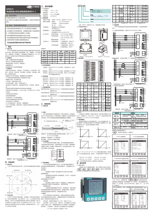
四、功能说明4.1 功率符号 KPM75提供双向的功率计算,功率及功率因数极性表示如图所示4.2 电能测量PUMG750记录正反双向有功、无功电能,记录正负双向电能之和,记录正负电能净值,可以记录本月,上月,上上月的有功无功电能和值。
PUMG750还提供复费率电能 ,波峰平谷四种费率 , 每天24 小时最多可以设置8个时段 , 时间设置步长为半个小时 , 可以记录波峰平谷四种费率总有功/无功电能 , 记录四种费率本月、上月、上上月有功/无功电能。
外形尺寸:96*96*88mm 开孔尺寸:91*91mm 俯视图开孔图3.3 端子接线四线星型系统:无电压互感器(PT)的直接接线(装置设置为3Ln3Ct)输出有功功率输入有功功率输出无功功率每个计算周期结束时更新计算需量值是上一个计算周期结束时的平均值15分钟计算周期 15分钟计算周期 15分钟时间(min )固定区块30 4500004mA20mA100%100%4mA20mA4mA20mA14mA20mA电压输出功率因数输出电流输出输出功率-1-100%100%)(装置设置为2LL2Ct )3.2 外形及开孔尺寸正视图测量数据,当测量数据(除电能数据)大于9999时,则所测数据的单位前显示“k ”,如kW 等;当大于99999999时,则显示“M ”,如“MW ”示例:KPM 75:额定380V /5A ,电能质量分析仪表。
一、概述1.1 功能介绍KPM75电能质量分析仪表采用先进的微处理器和数字信号处理技术设计而成。
集合全面的三相电量测量、显示、能量累计、电力品质分析、故障报警、开关量输入、继电器输出与网络通讯于一体。
抗干扰能力强 , 在电磁干扰较为严重的场合仍然能稳定地工作。
1.2 应用场合· 测量、监控配电系统中的电能参数· 成本中心分析需要的能耗数据采集· 限值监控报警(如过电压,电能消耗)· 电能质量分析· 绿色建筑或DCS 系统的数据测量1.3 功能特点· 测量三相相/线电压、三相电流、正/负序电压、正/负序电流、有功功率、无功功率、视在功率、有功电能、无功电能、功率因数、频率等三十余种基本电量· 测量显示月平均功率因数,准确掌握月无功用量情况· 0.5S 级的双向四象限电度统计及复费率统计功能· 需量统计功能,并记录最大值· 工作时间、负载时间统计功能· 可记录电压骤升、骤降、中断事件各50个· 支持高达63次谐波计算、总谐波畸变率计算、不平衡率、电流K 系 数· 计算电压的短时闪变值和长时闪变值以及波动极值· 标配1路RS485通讯接口,Modbus 协议,可扩展Profib us -DP 通 讯模块· 扩展4路无源开关量输入· 扩展4路继电器输出· 可扩展1路4~20mA 模拟量输出· 1路无源光耦集电极有功脉冲输出· 可扩展1路PT100温度输入· 256点/周波的电压、电流采样,测量精度高· 160*160点阵液晶,微背光显示 , 在强光和大视角环境下获得良好 的视觉效果二、技术参数2.1 环境条件工作温度: -25℃~+70℃储存温度: -30℃~+75℃ 相对湿度: 5%~95%无凝露 海拔高度: 3000米以下2.2 额定参数装置工作电源: 交流85~265VAC ,直流100~310VDC 额定交流数据: 相电压 57.7V /220V /400V 交流电流 5A 或1A (订货注明) 频 率 50Hz 开关量输入: 内部提供24VDC 直流电源 去抖时间40ms 继电器输出: 小型大功率继电器触点容量250VAC /5A ,30VDC /5A功 率 消 耗: 交流电压回路: 小于0.5VA /相(额定时) 交流电流回路: 小于0.75VA /相(5A 时) 小于0.25VA /相(1A 时) 装置电源回路: 小于3VA过 载 能 力: 交流电压回路: 1.2倍额定电压,连续工作 2倍额定电压,允许10S 交流电流回路: 1.2倍额定电流,连续工作20倍额定电流,允许1S 精度指标2.3 电气绝缘性能工频耐压: 符合GB /T13729-2002规定,工频电压2KV ,时间 1分钟绝缘电阻: 符合GB /T13729-2002规定,绝缘电阻不小于50M Ω 冲击电压: 符合GB /T13729-2002规定,承受1.2/50US 峰值为 5KV 标准雷电波的冲击2.4 机械性能振 动 响 应 :符合GB /T11287-2000规定,严酷等级为一级 振动耐久性:符合GB /T11287-2000规定,严酷等级为一级 冲 击 响 应 :符合GB /T14537-1993规定,严酷等级为一级 冲击耐久性:符合GB /T14537-1993规定,严酷等级为一级 碰 撞:符合GB /T14537-1993规定,严酷等级为一级2.5 电磁兼容性能静电放电抗扰度 : 符合GB /T17626.2-2006静电放电抗扰度规定严 酷等级为4级快脉冲群抗扰度 : 符合GB /T17626.4-2008快脉冲群抗扰度规定严 酷等级为4级浪涌抗扰度 : 符合GB /T17626.5-2008浪涌抗扰度规定严酷等级为 4级工频磁场抗扰度 : 符合GB /T17626.8-2008工频磁场抗扰度规定严 酷等级为4级三、选型安装3.1 选型标准注:端子5、6、7为标配RS485,端子28、29、30为备用RS485。
机械设备调试常用工具介绍

调试常用基本工具的工作原理、使用方法一、 调试常用基本工具认知无线高压核相器继电保护测试仪测振仪兆欧表(fluke1587)激光对中器温湿仪声级计风速仪红外线温度计手操器正时检测工具盘车器二、常用调试工具介绍红外线温度计红外线温度计可用于对非金属表面温度进行非接触式测量。
对于经氧化等处理或带涂层的金属表面也可以测量。
测量时,根据不同材料设定不同的发射率。
发射率表可以参考红外线温度计的说明书。
风速仪VS-001EXS电子风速仪是根据风压形变测定风的压力,利用风压与风速的关系来测定风速的。
除此之外,还有利用差压式风速仪、热导式风速仪、转轮式风速仪。
继电保护测试仪测试珈码Sverker 750继电保护测试仪可以测量时间(如动作时间、跳闸脉冲周期、电流、电压和阻抗)视在功率、有功功率、无功功率等。
频闪仪(转速表)PK2V频闪仪是通过在测量目标体上设置标识(反光条或者涂料或其他代替物),利用闪烁的速率来测量转速的仪器。
噪音计Center320噪音计可以测量30~130dB的噪音。
使用时根据需要选择不同的档位。
要测量人为感受的噪音选择“dBA”;要测量机械噪音选择“dBC”。
即时噪音选择“FAST”;测量平均噪音选择“SLOW”。
测振仪理音VA-11型振动分析仪可以检查机械振动及对不同的种类设备的工作状态进行分析。
该仪器有振动方式和FFT分析方式。
在振动方式中,可以同时进行加速度,速度及位移测量,并可以同时显示RMS值,峰值及封顶因素。
在分析方式中,FFT 用来决定光谱及振动波。
测量时,对于不同的转速的设备应选择不同参数来测量,不同设备类型应参照不同振动标准值,此外,还应根据规范要求科学地选择测试位置和方向。
高压核相器PD800W型高压核相器可以测量相角和相序测量。
该设备工作电压范围240V~800kV。
设备的参考探头和表计探头最远距离可达20米。
测量时,要求参考探头和表计探头与被测导体垂直并远离其它的导体,两个探头体与其他导体或者接地表面之间要保持至少70厘米的距离。
10KV进线CT

安装单位:6KV进线生产厂家:河南信电电器集团有限公司出厂日期:2011.11产品型号:LZZBJ9—12 额定频率:50HZ额定变比:600/5A 编号:11L23285A相直流电阻:1S1—1S2 1.203Ω 0.52S1—2S2 0.312Ω 10P20绝缘电阻:1S1—1S2对地≥500MΩ2S1—2S2对地≥500MΩ额定变比极性:(P1---S1同极性)1S1—1S2 变比合格P1---S1同极性2S1—2S2 变比合格P1---S1同极性伏安特性:1S1—1S2 0.1A 0.5A 1A 2A27.3V 28.3V 29.2V 30.0V 2S1—2S2 0.1A 0.5A 1A 2A105.9V 127.6V 132.9V 136.3V使用仪器QJ23a直流电阻型电桥FA—120CT变比极性伏安特性综合测试仪SVERKER 750继电保护测试仪DK—34B1多功能三相交流采样校验装置PC32—3兆欧表FLUKE 17B万用电表安装单位:6KV进线生产厂家:中国天水长开互感器制造有限公司出厂日期:2011.11产品型号:LZZBJ9—12 额定频率:50HZ额定变比:600/5A 编号:11L23283B相直流电阻:1S1—1S2 1.202Ω 0.52S1—2S2 0.313Ω 10P20绝缘电阻:1S1—1S2对地≥500MΩ2S1—2S2对地≥500MΩ额定变比极性:(P1---S1同极性)1S1—1S2 变比合格P1---S1同极性2S1—2S2 变比合格P1---S1同极性伏安特性:1S1—1S2 0.1A 0.5A 1A 2A27.2V 28.3V 29.5V 30.2V 2S1—2S2 0.1A 0.5A 1A 2A105.9V 126.6V 132.9V 135.3V使用仪器QJ23a直流电阻型电桥FA—120CT变比极性伏安特性综合测试仪SVERKER 750继电保护测试仪DK—34B1多功能三相交流采样校验装置PC32—3兆欧表FLUKE 17B万用电表安装单位:6KV进线生产厂家:中国天水长开互感器制造有限公司出厂日期:2011.11产品型号:LZZBJ9—12 额定频率:50HZ额定变比:600/5A 编号:11L23284C相直流电阻:1S1—1S2 1.201Ω 0.52S1—2S2 0.320Ω 10P20绝缘电阻:1S1—1S2对地≥500MΩ2S1—2S2对地≥500MΩ额定变比极性:(P1---S1同极性)1S1—1S2 变比合格P1---S1同极性2S1—2S2 变比合格P1---S1同极性伏安特性:1S1—1S2 0.1A 0.5A 1A 2A27.5V 28.5V 29.3V 30.2V 2S1—2S2 0.1A 0.5A 1A 2A103.9V 125.6V 132.9V 133.3V使用仪器QJ23a直流电阻型电桥FA—120CT变比极性伏安特性综合测试仪SVERKER 750继电保护测试仪DK—34B1多功能三相交流采样校验装置PC32—3兆欧表FLUKE 17B万用电表安装单位:#1变压器开关生产厂家:河南信电电器集团有限公司出厂日期:2011.11产品型号:LZZBJ9—12 额定频率:50HZ额定变比:200/5A 编号:11L23286A相直流电阻:1S1—1S2 0.630Ω 0.52S1—2S2 0.421Ω 10P20绝缘电阻:1S1—1S2对地≥500MΩ2S1—2S2对地≥500MΩ额定变比极性:(P1---S1同极性)1S1—1S2 变比合格P1---S1同极性2S1—2S2 变比合格P1---S1同极性伏安特性:1S1—1S2 0.1A 0.5A 1A 2A22.3V 25.3V 30.2V 31.0V 2S1—2S2 0.1A 0.5A 1A 2A75.9V 77.6V 80.2V 89.4V使用仪器QJ23a直流电阻型电桥FA—120CT变比极性伏安特性综合测试仪SVERKER 750继电保护测试仪DK—34B1多功能三相交流采样校验装置PC32—3兆欧表FLUKE 17B万用电表安装单位:#1变压器开关生产厂家:河南信电电器集团有限公司出厂日期:2011.11产品型号:LZZBJ9—12 额定频率:50HZ额定变比:200/5A 编号:11L23287B相直流电阻:1S1—1S2 0.633Ω 0.52S1—2S2 0.425Ω 10P20绝缘电阻:1S1—1S2对地≥500MΩ2S1—2S2对地≥500MΩ额定变比极性:(P1---S1同极性)1S1—1S2 变比合格P1---S1同极性2S1—2S2 变比合格P1---S1同极性伏安特性:1S1—1S2 0.1A 0.5A 1A 2A22.6V 25.7V 30.5V 31.8V 2S1—2S2 0.1A 0.5A 1A 2A75.5V 78.6V 80.8V 91.2V使用仪器QJ23a直流电阻型电桥FA—120CT变比极性伏安特性综合测试仪SVERKER 750继电保护测试仪DK—34B1多功能三相交流采样校验装置PC32—3兆欧表FLUKE 17B万用电表安装单位:#1变压器开关生产厂家:河南信电电器集团有限公司出厂日期:2011.11产品型号:LZZBJ9—12 额定频率:50HZ额定变比:200/5A 编号:11L23288C相直流电阻:1S1—1S2 0.635Ω 0.52S1—2S2 0.428Ω 10P20绝缘电阻:1S1—1S2对地≥500MΩ2S1—2S2对地≥500MΩ额定变比极性:(P1---S1同极性)1S1—1S2 变比合格P1---S1同极性2S1—2S2 变比合格P1---S1同极性伏安特性:1S1—1S2 0.1A 0.5A 1A 2A23.1V 24.6V 30.8V 31.2V 2S1—2S2 0.1A 0.5A 1A 2A75.5V 79.6V 80.8V 92.2V使用仪器QJ23a直流电阻型电桥FA—120CT变比极性伏安特性综合测试仪SVERKER 750继电保护测试仪DK—34B1多功能三相交流采样校验装置PC32—3兆欧表FLUKE 17B万用电表安装单位:#2变压器开关生产厂家:河南信电电器集团有限公司出厂日期:2011.11产品型号:LZZBJ9—12 额定频率:50HZ额定变比:150/5A 编号:11L23297A相直流电阻:1S1—1S2 0.554Ω 0.52S1—2S2 0.486Ω 10P20绝缘电阻:1S1—1S2对地≥500MΩ2S1—2S2对地≥500MΩ额定变比极性:(P1---S1同极性)1S1—1S2 变比合格P1---S1同极性2S1—2S2 变比合格P1---S1同极性伏安特性:1S1—1S2 0.1A 0.5A 1A 2A30.6V 34.2V 36.5V 38.8V 2S1—2S2 0.1A 0.5A 1A 2A88.5V 90.6V 95.1V 99.2V使用仪器QJ23a直流电阻型电桥FA—120CT变比极性伏安特性综合测试仪SVERKER 750继电保护测试仪DK—34B1多功能三相交流采样校验装置PC32—3兆欧表FLUKE 17B万用电表安装单位:#2变压器开关生产厂家:河南信电电器集团有限公司出厂日期:2011.11产品型号:LZZBJ9—12 额定频率:50HZ额定变比:150/5A 编号:11L23290B相直流电阻:1S1—1S2 0.555Ω 0.52S1—2S2 0.488Ω 10P20绝缘电阻:1S1—1S2对地≥500MΩ2S1—2S2对地≥500MΩ额定变比极性:(P1---S1同极性)1S1—1S2 变比合格P1---S1同极性2S1—2S2 变比合格P1---S1同极性伏安特性:1S1—1S2 0.1A 0.5A 1A 2A30.6V 34.2V 35.5V 38.3V 2S1—2S2 0.1A 0.5A 1A 2A88.5V 91.6V 95.1V 98.2V使用仪器QJ23a直流电阻型电桥FA—120CT变比极性伏安特性综合测试仪SVERKER 750继电保护测试仪DK—34B1多功能三相交流采样校验装置PC32—3兆欧表FLUKE 17B万用电表安装单位:#2变压器开关生产厂家:河南信电电器集团有限公司出厂日期:2011.11产品型号:LZZBJ9—12 额定频率:50HZ额定变比:150/5A 编号:11L23296C相直流电阻:1S1—1S2 0.556Ω 0.52S1—2S2 0.489Ω 10P20绝缘电阻:1S1—1S2对地≥500MΩ2S1—2S2对地≥500MΩ额定变比极性:(P1---S1同极性)1S1—1S2 变比合格P1---S1同极性2S1—2S2 变比合格P1---S1同极性伏安特性:1S1—1S2 0.1A 0.5A 1A 2A31.6V 34.2V 35.5V 38.9V 2S1—2S2 0.1A 0.5A 1A 2A87.5V 91.6V 95.8V 99.6V使用仪器QJ23a直流电阻型电桥FA—120CT变比极性伏安特性综合测试仪SVERKER 750继电保护测试仪DK—34B1多功能三相交流采样校验装置PC32—3兆欧表FLUKE 17B万用电表。
PS690U系列保护测控装置技术使用说明书V1.3
2009-12-24
2009-12-11 2009-7-27 2008-4-2 修改日期
* 技术支持
电话:(025)83537262
传真:(025)83537201
* 本说明书可能会被修改,请注意核对实际产品与说明书的版本是否相符
* 2010 年 8 月 第 1 版 第 1 次印刷
750kV电流互感器现场准确度校验测试 顺利完成 填补国际空白

I F OR M A TI N ON
国 网 电科 院 完 成 特 高压 C 验 收 VT
2 0 年9 2日至1 F 8日,荆 门站 、 晋 东 南 站和 南 阳站3 共计 1 台 10 0k 0 8 月2 ] O 站 8 0 V电容 式 电压 互 感 器 ( T) CV
同 比增 长 25 % :第 二产 业 用 电量 1 8 .4 k ・ .6 8 9 1 亿 W h,同 比 9 增 长 9 3 % 第 三 产 业 用 电 量 2 6 8 9 W ・h, 同 比 增 长 1 3 .8k 1 7 % ;城 乡居 民生 活用 电量3 0 0 9 亿k ・ , 同 比增 长 0.6 6 9 W h
业 用 电增 速 为 1 ,I 2 0 年 降 低7 3 4% ; 0 7 0 L . 个百 分 点 ,在 各 产业
中 降 幅 最 大 ,构 成 全 社 会 用 电增 速 下 降 的 主 要 原 因 ;期 间轻 工 业 用 电增 速 也 较 低 ,与 重 工 业 合 并 导 致 第 二 产 业 用 电增 速
熟 ,但 7 0k 及 以上 电压 等 级 电 流 互 感 器 准 5 V 确 度 校 验 现 场 检 测 仍 是 空 白 。 为解 决 7 0k 5 V
电流 互 感 器 现 场 ; 度 测 试 这 ~ 问题 ,西 北 佳确
设备累计平均利用小时数下降。 1 9 至 月份 ,全国发 电设备 累计平均
用 小 时 数 再 创 新 低 。 分 析 人 士认 为 ,短 期 内看 不 到 发 电量 下 滑 趋 势 改 观 的迹 象 ,这 也 将 抑 制 未 来 的 火 电投 资 冲 动 。 中 电 联 统计 ,1 月份 ,全 国全 社 会 用 电量 2 6 .9亿k ・ , 至9 62 99 W h 同 比 增 长 96 % 。其 中 ,第 一 产 业 用 电量6 0 8 ',W ・ .7 8 .8fk _ Z h,
- 1、下载文档前请自行甄别文档内容的完整性,平台不提供额外的编辑、内容补充、找答案等附加服务。
- 2、"仅部分预览"的文档,不可在线预览部分如存在完整性等问题,可反馈申请退款(可完整预览的文档不适用该条件!)。
- 3、如文档侵犯您的权益,请联系客服反馈,我们会尽快为您处理(人工客服工作时间:9:00-18:30)。
方 式〕 或 有电 压( 对 电 压 方 式)存 在。 这 些 指 示 可 让 你 在 测 试 前 用 于
检 查 有 关 的 电 路。
启动条件
计 时 器 可 用 以 下 方 法 启 动:
指示
启动条件
INT
a) 内 部 启 动。 即 由Sverker 750 启 动 测 试 程 序
(ON+TIME 或 OFF+TIME〕。
可 用 旋 钮 与 控 制 面 板 上 其 他 控 制 手 段 对 Sverker 750 进 行 设 置, 也 可 通 过 控 制 面 板 上 的 显 示 窗 口 进 行 许 多 其 他 设 置。
2、 系 统 部 件
2.1 标 准 设 备 物
品 1 型 Sverker 750 测试仪,115V 2 型 Sverker 750 测试仪,230V
并 随 之 显 示 测 量 结 果。
可 单 独 设 置 输 入 值 以 响 应 零 电 位 触 点 动 作 方 式 或 电 压(交流 或
直流)启 动 方 式。
输入状态指示器
每 次 进 行START( 启 动) 和STOP( 停 止) 输 入 操 作 时, 都 有 一 个
输 入 状 态 指 示 灯 作 指 示。 当 该 灯 亮 时, 表 明 某 一 电 路 闭 合 ( 对 触 点
步, 因 此, 激 活 启 动 开 关 的 瞬 间 有 益 于 消 除 测 试 误 差。
电 流 产 生 的 方 式 有 多 种, 可 通 过 显 示 窗 口 选 择( 见 第5 章)
电流产生方式
说明
持续产生直至被测对象
电流持续到计时器停止
动作完成
瞬 时 产 生( 手 动 控 制)
允 许 用 户 进 行 简 单 的 手 动 控 制。 当
750 自 动 返 回OFF 方 式。
一 些 量)。
* )当 动 作 发 生, 几 个 电 源 周 期 后 电 流 被 中 止。这 一 延 迟 用 于 模 拟 断 路 器 断 路 时 间, 延 迟 时 间 可 由 用 户 设 置。
有 电 流 时, 电 阻 器 组 右 边 的 指 示 灯 亮。 电 流 的 产 生 与 电 源 同
造 成 的 危 害。
• 千 万 不 要 把 水 或 其 他 任 何 溶 液 溅 在 Sverker 750 上。 • 对 Sverker 750 清 洁 前, 应 从 墙 壁 插 座 拔 下 插 头。 用 湿 布 清 洁。 请 勿 使 用 液 体 清 洁 器 或 溶 胶 清 洁 器。
• 不 要 使 用 Sverker 750 制 造 商 没 有 推 荐 使 用 的 其 他 辅 助 设 备, 以 免 发 生 危 害。
b) 当 停 止 输 入 端 加 电 压 或 接 点 闭 合 时。
c) 当 停 止 输 入 端 电 压 消 失 或 接 点 打 开 时。
b+c
d) 当 输 入 状 态 变 化 时。
测量外部信号周期 测 量 前, Sverker 750 必 须 设 置 为ON+TIME 状 态,随 之 计 时 器 也
67N 59 27 91 32
55 87 21 46N 51/86
79 94
其他应用 绘制磁化曲线 电流电压传感器变比测试 继电保护装置负载测试 阻抗测试 效率测试 极 性( 方 向) 测 试
1.3 设 计 与 结 构 Sverker 750 中 的 电 流 源 能 够 提 供0~10A,0~40A,0~100A,0~250V
交 流(AC)或0~300V 直 流(DC)。 可 在 电 流 产 生( 输 出)的 同 时 开 始 计 时, 当 继 电 保 护 装 置 动 作 时, 输 出 和 计 时 均 中 止。
Sverker 750 中 还 有 一 个 独 立 的 交 流 电 压 源, 变 化 范 围 为0~110V 交 流, 用 于 提 供 继 电 器 输 入 电 压。
Sverker 750 用户手册
Programma 物 品 编 号
CD-11100 CD-12300 ZP-CD01E
2.2 辅 助 设 备 物
品 测试线 运输箱 保护地线
Programma 物 品 编 号
GA-00030 GD-00180 GA-00200
3、 Sverker 750 说 明
3.1 概 述 本 章 对 Sverker 750 和 它 具 有 的 功 能 进 行 总 体 性 说 明 。有 关 的 详
被 清 零。
计时器清零 再 次 产 生 电 流 时 计 时 器 被 清 零。
测试自动重合闸设备 测 试 自 动 重 合 闸 设 备 前, 必 须 通 过 显 示 窗 口 进 行 设 置。 整 个 测
试 过 程 中ON+TIME 指 示 灯 亮。 每 当 计 时 器 启 动 输 入 激 活 时 都 有 电 流 产 生。
• 输 入 输 出 保 护 元 件 连 接 在 前 面 板 输 出/ 输 入 端 与 Sverker 750 保 护 地 接 头 之 间。
• 仪器产生的电压和电流可能对操作人员或测试中的设备是有害 的。
• Sverker 750 只 能 在 铭 牌 上 标 明 的 电 源 型 式 下 使 用。 • 为 保证安全,在 雷 暴 天 气 或 Sverker 750 长 时 间 无 人 监 视 或 长 久 不 使 用 时, 应 把 插 头 从 墙 壁 插 座 拔 下, 以 防 止 由 于 雷 电 和 电 源 冲 击 电 压
可 用 控 制 面 板 上 的 主 旋 钮 设 置 以 上 参 数 值, 电 流、 电 压 和 其 他
的 设 定 值 可 在 显 示 窗 口 中 显 示。 请 参 阅“ 电 流 表 与 电 压 表” 一 节。
电 流 接 通 和 关 断 与 启 动 开 关 的 四 个 位 置 对 应 关 系 如 下:
1、Sverker 750 继 电 保 护 测 试 仪 综 述
1.1 安 全 规 程
• 始终遵守本机安全规程 • 阅读并遵守以下规则 • 首 先, 连 接 保 护 地 线。 若 没 有 连 接 保 护 地 线, 则 Sverker 750上 不 能 外 加 电 压。请 用 绿/ 黄 色 电 缆 连 接。 • 若没 有 连 接 保 护 地 线,一定 不 要 在 Sverker 750上 外 加 电 压。 • Sverker 750 配 备 有 一 个 三 插 头 的 电 源 插 头, 这 个 插 头 仅 适 用 于 带 有 地 线 的 电 源 插 座。
• 不 要 试 图 自 己 维 修 Sverker 750 。 打 开 或 移 动 箱 盖 可 能 使 你 遭 受 危 险 电 压 和 其 他 的 危 害。
• 若 由 于 某 种 原 因 仪 器 需 要 返 还 时, 请 用 原 包 装 箱 或 相 同 强 度 的 包 装 箱, 否 则 运 输 中 可 能 被 损 坏。
细 介 绍 请 参 阅 第4 章 和 第5 章。
3.2 电 流 源
根 据 输 出 需 求 的 不 同, Sverker 750 中 的 电 流 源 能 提 供0~100A、 0~40A、0~10A、0~250V 交 流 或0~300V 直 流。 通 常,电 流 源 用 于 向 被 测 对 象 提 供 突 然 变 化 的 模 拟 故 障 条 件。
指示
状态
用途
ON+TIME 电 流 源 被 接 通( 激 活) 直 至 测 试 过... 继 电 器 动 作 时 间 测 试 对 象 动 作 完 成,并 显 示 (... 指 电 流、 电 压 或 其 他
当 时 时 间,随 后Sverker 750 自 一 些 量)。 动 返 回OFF 方 式。*
OFF
电 流 源 关 断。
关 断 电 流 源。
ON
电 流 源 接 通( 激 活)。
进 行 设 置 并 定 位 动 作/ 返
回 限 值。
OFF+TIME 电 流 源 被 关 断。 测 试 对 象 动 测 试 低... 继 电 器 动 作 时 间
作 时 显 示 时 间,随 后Sverker (... 指 电 流、 电 压 或 其 他
Sverker 750继电保护测试仪
中文操作手册
上海保珈玛电气设备有限公司
--------------------------------------------------------------------地址:上海市中山西路2368号华鼎大厦4号楼1104室 电话:(021)34250119 传真:(021)6456 1289 邮编:200235 电邮:cmsh@
b) 当 启 动 输 入 端 加 电 压 或 接 点 闭 合 时。
c) 当 启 动 输 入 端 电 压 消 失 或 接 点 打 开 时。
b+c
d) 当 输 入 状 态 变 化 时。
停止条件
计 时 器 可 用 以 下 方 法 停 止:
指示
停止条件
INT
a) 输 出 电 流 中 止 时(内 部 检 测)
Sverker 750 可 测 试 项 目 如 下:
继电器型式
IEEE 标 准 代
码
过电流继电器
50/76
反时限过电流继电器
51
低电流继电器
37
Байду номын сангаас
接地故障继电器
50
方向过电流继电器
67
方向接地故障继电器 过电压继电器 低电压继电器 方向电压继电器 功率方向继电器 功率因数继电器 差 动 保 护( 差 动 电 路 ) 距 离 保 护 装 置( 逐 相) 负序过电流继电器 电动机过载保护 自动重合闸装置 脱 扣(释 放)继 电 器 电压调节继电器 过 阻 抗 继 电 器(Z 大 于...) 低 阻 抗 继 电 器 (Z 小 于...) 热继电器 延时继电器