(1)LBG1-200.400高压电缆连接器说明书
Kabeldon 电缆配件说明书

SMPGB 3622 362 80-88 4209.2378SMPGB 3623 362 86-95 4209.2379SMPGB 3624 36293-103 4209.2380SMPGB 3625 362 101-111 4209.2381SMPGB 3626 362109-120 4209.2382* For lead sheathed cable add Pb at the end of type designation and forpoly metal-PE laminated cable add PAL (e.g. SMPGB 3622 Pb, SMPGB 3622 PAL).UseFor jointing XLPE- or EPR-insulated cables with aluminium and copper conductors and different types of cable sheaths.StandardMeets the requirements of: SS, IEC, IEEEDesignThe cable joint consists of a jointing tube with two premoulded adapters made of rubber, a screw cable clamp and a heat-shrink oversheath.See table below for diameter across the prepared insulation.The use of screws makes conductor jointing easier. Torque wrench, assembly coneand assembly tool RKM 362 are needed for assemblying.The joints are used for various types of screen, armouring and oversheath.Th e following cable data should be stated when ordering:– V oltage– Conductor cross section– Conductor material Cu or Al– Diameter across prepared insulation – Diameter over conductor – Screen, cross section and type – Outer diameter of the cablePremoulded cable jointSMPGB 362-420• Premoulded for safeand easy installation • Active pressure • Reliable• Joint bodies routine- tested according to IEC before delivery• Bolt connector technology • Compact joint for minimal cable stripping • Easy jointing of cables wi t h diff erent sizesFor SMPGB 420 kV contact us!Cable accessories 52-420 kVRKM 362Installation tool for SMPGB joint 362 kV .Max 3 mJSA 1 Al – – 130 6 Corrugated aluminium JSA 1 Pb 40-120* – 130 6 Lead sheathed or corrugated copper JSA 1 Pb 10 120-150* – 220 10 Lead sheathed or corrugated copper JSA 1 Pb 15 150-200* – 330 15 Lead sheathed or corrugated copper SCK 2-1 13-26 1 – – Metal-PE laminated as radial watertightness SCK 2-2 26-46 2 – – Metal-PE laminated as radial watertightness SCK 2-3 46-66 3 – – Metal-PE laminated as radial watertightness SCK 2-4 66-86 4 – – Metal-PE laminated as radial watertightness SCK 2-5 86-106 5 – – Metal-PE laminated as radial watertightness SCK 2-6 106-126 6 – – Metal-PE laminated as radial watertightness SCK 2-7 126-145 7 – – Metal-PE laminated as radial watertightnessEarthing kits for cable terminationsThe earthing kit connects the screen of the cable to the termination. The earthing kit is designed to handle the total screen cross section. It also provides the cable with a sealing.Cable with copper wire screen only. Cable with copper wire screen and metal-PE laminate. Metal-sheathed cable with or without screen wires. Cable with copper tape screen and cable with armouring.For corrugated screen made of:• Aluminium use JSA 1 Al • Copper use JSA 1 Pb • Stainless steel; contact usNo earthing kit is needed.Use earthing kit SCK 2.Use earthing kit JSA 1 Pb.Contact us.Note that the earthing kit increases the cableouter diameter by 20 mm!* Applicable for metalic sheath < 4 mm. For thicker metallic sheath contact us.Cable accessories 52-420 kVSKKBSKKB is a cross bonding kit for cables up to 170 kV . It can be mounted with advantage on already laid cable, where the load condition has changed and losses need to be reduced. Also gives the opportunity to optimize the cable system when cross-bonding can be chosen at a free position along the cable.AccessoriesOther dimensions on request.Selection guide for ARMSelecting ARM for unknown applications requires the length of joint "L" and diameter over joint "Ø" as below:E.g. Ø 115 and L 850 mm give ARM 3.ARM kit sizeThe kit consists of plastic mesh, spiral, fun-nel with holder, transparent tape and cast resin. The mesh and spiral are placed over the joint and sealed with the tape. The cast resin, which contains base and hardener in a partitioned bag, is mixed and poured intothe funnel until the mesh is full.The maximum storage temperature for the casting resin is 30 °C.ARM – Armouring kit for armoured cable SKKB 5 PAL < 50 Al laminate as radially watertightness SKKB 10 PAL 50-100 Al laminate as radially watertightness SKKB 15 PAL 100-150 Al laminate as radially watertightnessSKKB 5 MET < 50 For metallic screen with or without Cu screen wires SKKB 10 MET 50-100 For metallic screen with or without Cu screen wires SKKB 15 MET 100-140 For metallic screen with or without Cu screen wires SKKB 5 CUW < 50Cu screenSKKB 10 CUW 50-100 Cu screenSKKB 15 CUW 100-150 Cu screenAll dimensions in mmARMFor restoring the armouring when jointing armoured cables.Design:5001000L (mm)60100Ø (mm)140Tools and oilAll dimensions in mmAV 6220Sheath removing tool for PE-sheathed cable Ø > 20 mm.RKM 670Cable knife, 30 mm blade.RKM 672Sheath removing knife, with two handles, for XLPE cable.730RTorque wrench for screw connectors, screw cable lugs, overhead line clamps, etc.Supplied with 7 mm socket head, extension arm and 8 mm internal hexagon head.Torque range 6-50 Nm.RKM 130Torque wrench for screw connectors, screw cable lugs, overhead line clamps, etc. Torque wrench can be used with standard 1/2" sockets.Torque range 25-130 Nm.IG 1801 Synthetic insulating oil 4 Tin IG 1803 Synthetic insulating oil 2 TinIG 1804 Synthetic insulating oil 5 Tin IG 1805 Synthetic insulating oil 60 Drum IG 1807Synthetic insulating oil190DrumIG 180XSynthetic insulating oil.RKM-FVVessel heater. Fits RKM 670 Cable knife RKM 130 Torque wrench 25-130 Nm RKM 672 Sheath removing knife RKM-PM Manual oil fi lling equipment AV 6220 Sheath removing tool RKM-FV V essel heater 730 R Torque wrench 6-50 NmCable accessories 52-420 kVAll dimensions in mmToolsMB 1 Outer sheath breaker (pack of two)SH 50 XLPE-shaver 15-50SH 80 XLPE-shaver 40-80SH 130 XLPE-shaver 70-130SV 140 Installation tool for stress cone, SKG SV 190 Installation tool for stress cone, SKGBSV 215 Installation tool for stress cone, SKGESV140, SV190, SV 215Tools for installation of stress cones as following:- SV 140 for SKG - SV 190 for SKGB - SV 215 for SKGEMB 1Cable sheath breaker.SH 50, SH 80, SH 130Tool for removing and tapering XLPE-insulation and for removingouter conductive layer.。
电缆连接器安装说明书
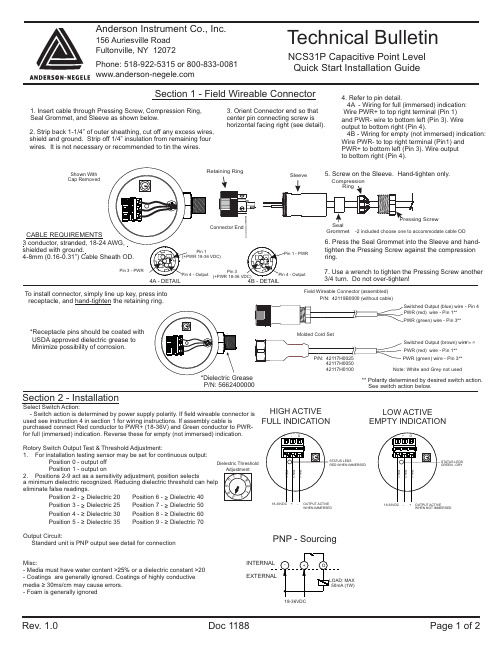
2. Strip back 1-1/4”of outer sheathing, cut off any excess wires,shield and ground. Strip off 1/4”insulation from remaining four wires. It is not necessary or recommended to tin the wires.1. Insert cable through Pressing Screw, Compression Ring,Seal Grommet, and Sleeve as shown below.CABLE REQUIREMENTS3 conductor, stranded, 18-24shielded with ground.Shown With Cap Removed3. Orient Connector end so that center pin connecting screw is horizontal facing right (see detail).4. Refer to pin detail.4A - Wiring for full (immersed) indication:Wire PWR+ to top right terminal (Pin 1)and PWR- wire to bottom left (Pin 3). Wire output to bottom right (Pin 4).4B - Wiring for empty (not immersed) indication:Wire PWR- to top right terminal (Pin1) and PWR+ to bottom left (Pin 3). Wire output to bottom right (Pin 4).5. Screw on the Sleeve. Hand-tighten only.6. Press the Seal Grommet into the Sleeve and hand-tighten the Pressing Screw against the compression ring.7. Use a wrench to tighten the Pressing Screw another 3/4 turn. Do not over-tighten!Connector EndSection 1 - Field Wireable ConnectorNCS31P Capacitive Point Level Quick Start Installation GuideRev. 1.0 Doc 1188 Page 1 of 2Technical BulletinAnderson Instrument Co., Inc.156Auriesville Road Fultonville, NY 12072Phone: 518-922-5315 or To install connector, simply line up key, press into receptacle, and the retaining ring.hand-tighten *Receptacle pins should be coated with USDA approved dielectric grease to Minimize possibility of corrosion.P/N: 5662400000Grommet-2 included choose one to accommodate cable OD4B - DETAILPin 3Section 2 - InstallationWHEN IMMERSEDHIGH ACTIVE FULL INDICATIONWHEN NOT IMMERSEDLOW ACTIVE EMPTY INDICATIONPNP - Sourcing18-36VDC(1W)4A - DETAIL ** Polarity determined by desired switch action.See switch action below.Field Wireable Connector (assembled)PWR (red) wire - Pin 1**PWR (green) wire - Pin 3**P/N: 42119B0000 (without cable)Switched Output (blue) wire - Pin 4Select Switch Action:- Switch action is determined by power supply polarity. If field wireable connector is used see instruction 4 in section 1 for wiring instructions. If assembly cable ispurchased connect Red conductor to PWR+ (18-36V) and Green conductor to PWR-for full (immersed) indication. Reverse these for empty (not immersed) indication.Rotory Switch Output Test &Threshold Adjustment:1. For installation testing sensor may be set for continuous output:Position 0 - output off Position 1 - output on2. Positions 2-9 act as a sensitivity adjustment, position selects a minimum dielectric recognized. Reducing dielectric threshold can help eliminate false readings.Position 2 -Dielectric 20 Position 6 -Dielectric 40≥≥Position 3 -Dielectric 25 Position 7 -Dielectric 50≥≥Position 4 -Dielectric 30 Position 8 -Dielectric 60≥≥Position 5 -Dielectric 35 Position 9 -Dielectric 70≥≥Output Circuit:Standard unit is PNP output see detail for connectionMisc:- Media must have water content or a dielectric constant 20>25%>- Coatings are generally ignored. Coatings of highly conductive media 30ms/cm may cause errors.≥- Foam is generally ignoredDielectric ThresholdMolded Cord Set42117H0100Switched Output (brown) wire PWR (red) wire - Pin 1**Note: White and Grey not used- Pin 4Rev. 1.0 Doc 1188 Page 2 of 2Section 3 - SpecificationOperation/Environmental Specifications Ambient Temperature Limits:14 - 140°F (-10 - 60°C)Pressure Rating:150 PSI (10 BAR) max Process Temperature Limits:32 - 212°F (0 - 100°C)CIP Cleaning:109°F (143°C) for 120 minute Function:Full/empty signal determined by wiringResponse Time:0.1sMinimum Dielectric Threshold:Selectable from 20-70Electrical Specifications Voltage Required:18 to 36 Vdc (≤20mA)Power Consumption:0.6 W Typ. (i.e. 25mA at 24 Vdc)Signal Output:PNP - Sourcing (active 50mA)Signal Transmission Power:≤1mwConnection:One 3 pin M12 Micro-mini electrical connector (QDR)Mechanical Specifications Wetted Materials:316L SS, USP class VI PEEK Material certificates includedWetted Finish:Metal Surfaces Ra = 8 microinch max Polymeric Surfaces = 25 microinch max Surface finish certificate included Housing Material:300 series Stainless Steel housing,lid and threaded connection(non contact surfaces)Enclosure Protection:NEMA 4X, IP69K Agency Approval:CE compliant;ASME BPE 2012 compliantVisual Indication Status LED:Red - Probe Immersed Green - Probe DryWarranty:2 yearsATTENTION: CONNECTOR WIRINGPin1 - 18-36 VDC VDC ComPin3 - VDC Com 18-36 VDC Pin4 - Switch Output MAX 50 mARefer to technical bulletin for Anderson cable color codingFull Ind Empty IndSENSOR ENDPIN 3PIN 1PIN 41.97”50mm1.97”。
高压电缆接线器型F接入器安装说明书

Page 1 of 12IS97029-ENG - R909TB/G-CW5AT/S31 October 2017 - Revision 2 - Supersedes edition of 4 April 2017M485n e c e s s a r y l e n g t h o f s c r e e n w i r e e a r t h c o n n e c t i o nequipment bushing (type F interface )outer cablesheath1 Train the cable into the approximate finished position next to the equipment bushing.2 Mark the centre line « M » of the bushing.3 Mark the outer cable sheath at a point 485 mm from the centre line « M » of the bushing (reference point A ). Caution: In the case of conductive coated outer cable sheaths, the conductive coating must be removed during the installation of accessories in order to be able to carry out e.g. cable sheath testing. For this purpose, the conductive coating of the outer cable sheath must be removed with a suitable stripping tool for a length of approx. 400 mm below the reference point A .EQUIPMENTNB : Only one phase is shown in these instructions. Make off all three phasesthe same way. Use a cable conversion kit for 3-core cables.CABLE PREPARATIONA400Page 3 of 12I S 97029-E N G - R 909T B /G -C W 5A T /S - R e v i s i o n 2Page 4 of 12Page 5 of 12core insulationsemi-conductive screenu Slide the heat-shrink tube over the cable.70core insulationconductorconductor contactprotective adhesive tapeconductor1 A. For compression type contacts : remove the core insulation from the conductor for a distance « C » mm (C = depth of contact bore + 15 mm).1 B. For mechanical type contacts : remove the core insulation from the conductor for a distance « C » mm (C = depth of contact bore + 10 mm).2 Slightly bevel the edge of the core insulation. Do not sharpen in cone-shape.3 Thoroughly clean core insulation. Always wipe towards the screen wires.4 As a protection, wrap a few turns of adhesive tape around the conductor end.REMOVAL OF THE CORE INSULATIONA. Compression type contacts (Type TBC-X)B. Mechanical type contacts (Type TMBC-X)15C bevelcore insulationconductor contactconductor10Cbondedsemi-conductive screen38545-50core insulationK400i Cut the cable at a distance of 385 mm from the edge of the copper woven fabric tape.o Remove the semi-conductive screen up to 70 mm above the edge of the copper woven fabric tape.p Create a smooth conical transition between cable insulation and semiconductive screen (use appropriate tools and emery cloth, K400), leaving 45-50 mm of the semi-conductive screen above the edge made with the copper fabric tape.q Remove any traces of conductive residue from the core insulation.heat-shrink tubesmooth conical transitionIMPORTANT :Slightly roughen the insulation surface using emery cloth K400.!I S 97029-E N G - R 909T B /G -C W 5A T /S - R e v i s i o n 2Page 6 of 12Page 7 of 12holding toolcontact palmequipment bushing1 For aluminium conductors : before installing the conductor contact, wire brush the conductor.2 Insert, if necessary, the centre ring into the contact barrel according to the table in the contact installation instruction.3 Position the contact taking care that the contact hole aligns with the bushing hole.4 Before tightening, distance « Z » must be between 230 and 235 mm.5 Tighten the contact. Please refer to the installation instruction included with the contact.6 After tightening, distance « Z » must be between 230 and 240 mm.If necessary, adjust the position of the cable reducer until distance « Z » is within the tolerance range.Mechanical type contacts (Type TMBC-X)Bcable reducerBefore tighteningAfter tighteningconductor contactZ = 230 - 235Z = 230 - 240I S 97029-E N G - R 909T B /G -C W 5A T /S - R e v i s i o n 2Page 8 of 12Page 9 of 12CONNECTOR INSTALLATION ON BUSHINGconnector housinglubricate5 A: Install the spring washer and M16 nut on to the threaded stud. B: Install the M16 flange nut on to the threaded stud.6 Use torque wrench with a socket wrench 22 and tighten exerting 50 Nm (5 kgm or 36,9 foot-pounds) of torque. In order to achieve the correct applied torque ensure that there is no lubricant on the threaded parts.* USE ONLY THE SILICONE LUBRICANT SUPPLIED3 Clean and lightly lubricate* both connector and bushing interface.4 Push the connector on to the bushing.M16 studequipment bushingequipment bushing8 mm hex key 1/2" - 12,7 mm torque wrench8 mm socket13 mm wrench8mmor30 Nm1 Install M16 threaded stud into the bushing interface.2 Using a 13 mm wrench or a hex key of 8 mm, tighten the stud exerting 30 Nm (3 kgm or 22,1 foot-pounds).Position of the stud :The longest side with inside hex outside of the bushing interface.!!inside hex22 mm socket50 Nm1/2" - 12,7 mm torque wrenchL ≥ 90 mm extension M16 nut22mmspring washerM16 flange nutorA BI S 97029-E N G - R 909T B /G -C W 5A T /S - R e v i s i o n 2Page 10 of 12* USE ONLY THE SILICONE LUBRICANT SUPPLIED24mm1/2" - 12,7 mm torque wrench24 mm socketINSTALLATION OF THE BASIC INSULATING PLUGlubricatebasic insulating plug1 Clean and lubricate* the insulating plug for the opposite side of the connector.2 Insert the plug in the connector and tighten it untill the plug noticably blocks in its end position (no furtherrotation is possible), using a torque wrench with a socket of 24 mm. Remark : The required torque may exceed 70 Nm.3 Once the plug is blocked, apply a torque of 70+5 Nm to secure.070+5 Nm0Page 11 of 12I S 97029-E N G - R 909T B /G -C W 5A T /S - R e v i s i o n 2INSTALLATION OF THE CAPCONNECTOR EARTHING AND CABLE CLAMPINGNOTE :A connector/bushing mated combination should not be allowed to carry the full weight of the cable.Therefore it is necessary to clamp the cable as close as possible to the connector.IMPORTANT NOTES :- Never disconnect the connector from energised equipment nor energise a disconnected connector without previously installing on its appropriate corresponding mating part.- Do not allow hydrocarbon oils or solvents to contaminate the E.P .D.M. rubber. In the event of contamination, wipe the surface clean with a dry cloth.protective capsystem earthcable clampscreen wires1 Bend back the screen wires along the outer sheath to form a pig tail.2 Connect the earthing lead and screen wires to the system earth.earthing leadInstallation on insulating plug :Clean the inside of the cap and the outside surface of the connector and insulating plug. Push the cap over the connector and on to the insulating plug. Slightly pull up the edge of the cap to exhaust the air duringassembly. Press the centre of the cap on to the locking point until it snaps in place. Position the cap with the pulling tab pointing downwards.Nexans Network Solutions NV - div. EUROMOLDZuid III - Industrielaan 12B-9320 EREMBODEGEM-AALST – BELGIUMTel: +32 (0)53/85 02 11 – Telefax: +32 (0)53/83 10 13sales.euromold@I S 97029-E N G - R 909T B /G -C W 5A T /S - R e v i s i o n 2Page 12 of 12。
Dixon 高压翼式高压胶带接头说明说明书

Customer Service 877.963.4966WS-Series WS-BOP Series2877.963.4966 • WS and WS-BOP SeriesHigh Pressure Wingstyle Hydraulic CouplingsHeavy duty 'spider' valve holder resists surge flow and pressurized connectionsRugged high-strength steel sand-cast wing nut for threaded connect and disconnect operation Re-buildable valve and easy seal replacement316 stainless steel couplings - threads are coated to prevent galling during connection and disconnectionApplications • Oil field (hydraulic supply lines, blow out preventer, pipe spinners, top drives, and coil tubing units)• Construction (pile drivers, tampers, hydraulic hammers, and submersible pumps)• Offshore (supply reels, platform jack-up systems, and water pump systems)Sizes • 3/4" - 2"Features • View ports available on request (except for BOP models)• Steel componentry plated using ROHS compliant zinc nickel • Main valve seal is housed to improve seal integrity during pressured connection and disconnection • NPTF , BSPP , Code 62 flange, and ORB • Parker Snap-Tite 75 Series, Hydraulics Incorporated 5TV Series, Stucchi VOF , Faster OGV, and DNP VFF-HDMaterials • Body: steel and 316 stainless steel • Seal: nitrile, FKM, and EPDM • Dust caps/plugs: aluminum with steel cableSpecifications • 5000 PSI working pressure for steel, 3000 PSI working pressure for 316 stainless3877.963.4966 • WS and WS-BOP SeriesWS coupler with view port4877.963.4966 • WS and WS-BOP SeriesBody Size Part Details Length Maximum OD Pkg Qty Part #Threads Material Inch mm Inch mm 3/4"WS6F41/2" - 14 NPTF steel 3.2783.1 1.7444.25WS6F63/4" - 14 NPTF steel 3.2783.1 1.7444.25WS6F6-SS 3/4" - 14 NPTF 316 stainless 3.2783.1 1.7444.25WS6BF63/4" - 14 BSPP steel 3.2783.1 1.7444.25WS6BF6-SS 3/4" - 14 BSPP 316 stainless 3.2783.1 1.7444.25WS6OF61-1/16" - 12 ORB steel 3.2783.1 1.7444.251"WS8F81" - 11-1/2 NPTF steel 4.18106.2 2.2557.25WS8F8-SS 1" - 11-1/2 NPTF 316 stainless 4.18106.2 2.2557.25WS8BF81" - 11 BSPP steel 4.18106.2 2.2557.25WS8BF8-SS 1" - 11 BSPP 316 stainless 4.18106.2 2.2557.25WS8OF81-5/16" - 12 ORB steel 4.18106.2 2.2557.251-1/4"WS10F101-1/4" - 11-1/2 NPTF steel 5.38136.7 2.6366.81WS10F10-SS 1-1/4" - 11-1/2 NPTF 316 stainless 5.38136.7 2.6366.81WS10BF101-1/4" - 11 BSPP steel 5.38136.7 2.6366.81WS10BF10-SS 1-1/4" - 11 BSPP 316 stainless 5.38136.7 2.6366.81WS10OF101-5/8" - 12 ORB steel 5.38136.7 2.6366.811-1/2"WS12F121-1/2" - 11-1/2 NPTF steel 5.98151.9 3.2582.61WS12F12-SS 1-1/2" - 11-1/2 NPTF 316 stainless 5.98151.9 3.2582.61WS12BF121-1/2" - 11 BSPP steel 5.98151.9 3.2582.61WS12BF12-SS 1-1/2" - 11 BSPP 316 stainless 5.98151.9 3.2582.61WS12OF121-7/8" - 12 ORB steel 5.98151.9 3.2582.612"WS16F162" - 11-1/2 NPTF steel 7.05179.1 4.00101.61WS16F16-SS 2" - 11-1/2 NPTF 316 stainless 7.05179.1 4.00101.61WS16BF162" - 11 BSPP steel 7.05179.1 4.00101.61WS16BF16-SS 2" - 11 BSPP 316 stainless 7.05179.1 4.00101.61WS16OF162-1/2" - 12 ORB steel 7.05179.1 4.00101.61Female Threaded PlugsSteel316 stainlessInteriorExterior5877.963.4966 • WS and WS-BOP SeriesBody Size Port Size SteelPart #3/4"3/4"6WSFP61"1"8WSFP81-1/4"1-1/4"10WSFP101-1/2"1-1/2"12WSFP122"2"16WSFP16Flange Pad CouplersBody Size Port Size SteelPart #3/4"3/4"WS6FP61"1"WS8FP81-1/4"1-1/4"WS10FP101-1/2"1-1/2"WS12FP122"2"WS16FP16Flange Pad PlugsBody Size Port Size SteelPart #3/4"3/4"WS6FH61"1"WS8FH81-1/4"1-1/4"WS10FH101-1/2"1-1/2"WS12FH122"2"WS16FH16Flange Head Plugs6877.963.4966 • WS and WS-BOP SeriesRigid Dust Plugs Body Size Aluminum Body With Steel Cable Part #3/4"6WSDP-A 1"8WSDP-A 1-1/4"10WSDP-A 1-1/2"12WSDP-A 2"16WSDP-A Accessories Rigid Dust CapsBody Size Aluminum Body With Steel Cable Part #3/4"WS6DC-A 1"WS8DC-A 1-1/4"WS10DC-A 1-1/2"WS12DC-A 2"WS16DC-A Seal Kits Body Size Coupler Style Seal Kit Contents Nitrile Part #3/4"all body / valve seals and retaining rings 6WS-SKIT 1"all body / valve seals and retaining rings 8WS-SKIT 1-1/4"all body / valve seals and retaining rings 10WS-SKIT 1-1/2"all body / valve seals and retaining rings 12WS-SKIT 2"all body / valve seals and retaining rings16WS-SKIT Repair Kits Body Size Coupler Style Repair Kit Contents Nitrile Part #3/4"all valve assembly, O-ring, and PTFE B.U.6WS-RKIT 1"all valve assembly, O-ring, and PTFE B.U.8WS-RKIT 1-1/4"all valve assembly, O-ring, and PTFE B.U.10WS-RKIT 1-1/2"all valve assembly, O-ring, and PTFE B.U.12WS-RKIT 2"all valve assembly, O-ring, and PTFE B.U.16WS-RKIT7877.963.4966 • WS and WS-BOP Series • R ed powder coated components and external O-rings for easy BOP service identification• S teel components are plated using ROHS compliant zinc nickel• I ndividually marked with the BOP series designation, API 16D specification and date code Specification • Pressure rating 5000 PSIApprovals • F ire tested and Lloyd's certified to 1300°F (700°C ) in accordance with API 16D• C ertificate available upon request Female Threaded CouplersFemale Threaded Plugs Seal KitsBody Size Coupler Style Repair Kit Contents FR FKM Part #3/4"all body / valve seals and retaining rings 6BOP-SKIT1"all body / valve seals and retaining rings 8BOP-SKIT1-1/4"all body / valve seals and retaining rings 10BOP-SKIT1-1/2"all body / valve seals and retaining rings 12BOP-SKIT2"all body / valve seals and retaining rings 16BOP-SKITBody Size Threads Steel Part #316 Stainless Steel Part #3/4"1/2" - 14 NPTF 6WSF4-BOP ---3/4" - 14 NPTF 6WSF6-BOP 6WSF6-SS-BOP1"1" - 11-1/2 NPTF 8WSF8-BOP 8WSF8-SS-BOP1-1/4"1-1/4" - 11-1/2 NPTF 10WSF10-BOP 10WSF10-SS-BOP1-1/2"1-1/2" - 11-1/2 NPTF 12WSF12-BOP 12WSF12-SS-BOP2"2" - 11-1/2 NPTF 16WSF16-BOP 16WSF16-SS-BOPBody Size Threads Steel Part #316 Stainless Steel Part #3/4"1/2" - 14 NPTF WS6F4-BOP ---3/4" - 14 NPTF WS6F6-BOP WS6F6-SS-BOP1"1" - 11-1/2 NPTF WS8F8-BOP WS8F8-SS-BOP1-1/4"1-1/4" - 11-1/2 NPTF WS10F10-BOP WS10F10-SS-BOP1-1/2"1-1/2" - 11-1/2 NPTF WS12F12-BOP WS12F12-SS-BOP2"2" - 11-1/2 NPTF WS16F16-BOPWS16F16-SS-BOPNotes8877.963.4966 • WS and WS-BOP Series9877.963.4966 • WS and WS-BOP Series CopyrightCopyright © 2021 by Dixon Valve and Coupling Company, LLCAll rights reserved. This book is copyrighted material. Use, reproduction or copying of it by anyone other than Dixon ® is strictly forbidden without its express written consent.Limits of LiabilityThis catalog is intended as a product offering. It is not intended to be a user or technical manual. Information in this catalog is subject to change without notice. All users and distributors of products sold through this catalog should contact Dixon with questions of use, compatibilities, coupling procedures, and life of product. Our full-time engineering and test staff are always available to recommend uses and to assist distributors and users with any questions.not manufactured by Dixon, the warranty of such items being limited to the actual warranty extended to Dixon by its supplier; (b) any product that has been subject to abuse, negligence, accident, or misapplication; (c) any product altered or repaired by others than Dixon; and (d) to normal maintenance services and the replacement of service items (such as washers, gaskets, and lubricants) made in connection with such services. To the extent permitted by law, this limited warranty shall extend only to the buyer and any other person reasonably expected to use or consume the goods who is injured in person by any breach of the warranty. No action may be brought against Dixon for an alleged breach of warranty unless such action is instituted within one (1) year from the date the cause of action accrues. This limited warranty shall be construed and enforced to the fullest extent allowable by applicable law.Other than the obligation of Dixon set forth herein, Dixon disclaims all warranties, express or implied, including but not limited to any implied warranties of merchantability or fitness for a particular purpose, and any other obligation or liability. The foregoing constitutes Dixon's sole obligation with respect to damages, whether direct, incidental, or consequential, resulting from the use or performance of the product.Some products and sizes may be discontinued when stock is depleted or may require a minimum quantity for ordering.TrademarkKamvalok ®is a registered trademark of OPW Engineered Systems.SafetySafety logos, which appear throughout our catalog, are used as a reminder that the user should carefully review for the appropriateness of the product for the media, application, and environment in which it will be used.NOTE: Because of the health hazards associated with contamination and lead content in drinking water systems, Dixon couplings, unless otherwise specifically approved, are not recommended for potable water service and should not be used in applications where drinking water will contact the wetted surfaces of the coupling.WARNING: Dixon products may contain chemicals known to the State of California to cause cancer, birth defects, or other reproductive harm.© 2021 DVCC Printed in the USA WSSERIES_621_WEB 2925 Chief Court Dallas, NC, 28034Phone: 800.839.8980·704.334.9175fx: 800.839.9022·704.334.9002Email:********************Dixon Quick Coupling connect with us on。
电缆接钳系列产品说明说明书

Industrial connectivityCable glands for tray, non-armored and armored cableTray cable solutionsCable glands for tray, non-armored and armored cableFast & easy installation. Gland solutions for tray cableEaton's Crouse-Hinds series cable glands are used in hazardous, industrial and commercial applications throughout the world, engineering safety and productivity in the most severe environmental conditions.Our global offering provides a termination solution for virtually every cable type used in hazardous and industrial environments. Designed for strict adherence to global specifications meeting North American and international codes and standards, including NEC, CEC, ATEX, IECEx and regionalcertifications.*Type TC-ER-HL cable is rated for 600 V nominal. Overall cable diameters are 25 mm (1 inch) or less.**Suitable for Class I, Division 2 hazardous locations when installed in accordance with NEC501.10(B)(4).†Temperatures listed are operating temperatures. For additional certification information, consult factory.CGB, CGD and CGECGB cord and cable connectors have been updated to accommodate termination of an even greater variety of cords and cables in dry and wet locations.• Now certified for use with non-armored cords and cables, including tray cable types TC, TC-ER, TC-ER-HL*, ITC-ER and more!• Now UL Listed for use in wet locations and sunlight resistant• Updated NEMA certifications - NEMA 4 in steel; NEMA 4X in aluminum• Tested and listed with increased pull-out rating to 50 lbs. as required by UL for tray and TC-ER cables.• Rugged, durable construction protects cords and cables from damage, and compact design permits close grouping of several cords and/or cables.• Flexible offering available in both steel, iron and aluminum in 3/8” to 3” trade sizes in straight, 45° and 90° angles.•Wire mesh grips available for added strain relief!ADE-1F2 and ADE-1FCADE-1F2 and ADE-1FC cable glands are designed to provide a flameproof and weatherproof seal on the outer sheath of non-armored tray cable and marine shipboard or type P cable. ADE glands are available in a wide range of materials and sizes to suit any application. The ADE series is ideal for termination of cords and cables (including tray cables and TC-ER) with a wide range of global certifications and material options.•The ADE-1F2 series is the ideal non-explosionproof gland for termination of cords and cables, tray cables (including TC-ER cable) when a wide range certifications, temperature range and material options are required.•Designed for use in hazardous locations, the ADE-1FC series is the perfect barrier gland solution now certified Class I, Divisions 1 & 2, Groups A, B, C, and D for use with TC-ER-HL* cables, and carries a wide range of certifications, temperature ranges and material options.T erminator II TMCXTerminator ™ II TMCX cable glands are truly universal hazardous location barrier cable glands designed for termination of armored, non-armored (including TC-ER-HL*) and TECK armored cables.•Unique design features and broad range of sizes and materials, coupled with our fast-curing Chico ® LiquidSeal compound and bulk packaging options, make the Terminator II TMCX the easiest, safest and most versatile cable termination solution available!3EATON'S CROUSE-HINDSOrdinary location/heavy industrial use **Hazardous rated useTemperature Sealing Specifiable TemperatureSealing Specifiable ADE-1FCCGB, CGD and CGE Cable types:TFeatures• Rugged, durable construction protects cords and cables from damage and compact design permits close grouping of several cords and/or cables• Flexible offering available in both steel iron and aluminum in 3/8” to 3” trade sizes in straight, 45° and 90°• Wire mesh grips available for added strain relief• Available with NPT threads• Standard neoprene bushing weatherproof seal on outer sheath of cable Materials:CGB• Form A - D bodies and gland nuts – steel with zinc electroplate and chromate finish coat• Form E - F bodies and gland nuts – Feraloy® iron alloy with electrogalvanized and aluminum acrylic paint• Available in all aluminum construction• Bushing – standard neoprene bushing included, silicon optional CGD and CGE• Body – Feraloy iron alloy• Gland nut – steel4EATON'S CROUSE-HINDS Certifications and compliances:CGB• cULus Listed – UL File E23223• Suitable for use in Class I, Div. 2 hazardous locations when installed in accordance with NEC501.10(B)(4)• NEMA 3R: suitable for use in wet locations• NEMA 4: 3/8" to 3" steel• NEMA 4X: 3/8" to 1½” aluminumCGD and CGE• cULus Listed – UL File E23223• Suitable for use in wet locations•NEMA 4: steelCGB396CGB396 SA BUSH96RPE417-117* Not available with optional sealing gasket and locknut.**Type TC-ER-HL cable is rated for 600 V nominal. Overall cable diameters are 25 mm (1 inch) or less.† Not NEMA 4 or NEMA 4X rated.‡ Max operating temperature of bushing only, glands UL Listed to -25°C to +40°C.Ordering information – CGB straight connectorPart number example5EATON'S CROUSE-HINDSCable sealing range (E)DimensionsNPT thread Steel part Aluminum Across hex flats Acrosshex corners (G)Neoprene bushing part number 80°C‡Wire mesh grip1.656BUSH97Ordering information – CGE 90° connectorNeoprene bushing part number 80°C‡SiliconeBUSH92Part number exampleCGE194 SGCGE cable gland, 1/2" NPT thread size, aluminum, sealing gasket and locknutCable sealing range (E)DimensionsNPTPartNeoprenebushing part number Siliconebushing part numberWire meshgrip part8EATON'S CROUSE-HINDSABDesign features:Specifically formulated elastomer – used on the outer sheath ofthe cable provides IP66 or IP68 moisture ingress protection B Optional external clamp – provides additional external strain relieffor rugged applicationsADE-1F2 cable glands are designed to provide a flameproof and weatherproof seal on the outer sheath of non-armored, tray, marine shipboard or type P cable. ADE glands are available in a wide range of corrosion resistant materials to suit any harsh, industrial applications.ADE-1F2Non-armored and tray cable – TC-ER (HL)Unarmoured / Tray CableSteel Tape Armoured cableBronze braided / Tinned Copper Wire Braid marine shipboard cableLead sheathed cable (with addition ofearthing washer)cableShipping application:• ABS 14-HS1274083-PDA • BV 40910/A0 BV • DNV TAE000010X • Lloyds 11/00072• DTS-01:1991 compliantOperating temperature:• -60°C to +140°CMaterials:• Nickel-plated brass for superior corrosion resistance•316 stainless steel, bronze and aluminum options available. It is recommended that a suitable lubricant be used on all threads of stainless steel and aluminum versions.Ingress protection (IP):• II2GD / Ex db IIC / Ex eb IIC / Ex tb IIIC UL certification3DJN E310130 ; Class I, Zone 1, AEx e IIADE sizes 3 to 8, ½” to 1¼” NPT or ISO 20 to 40 with TC installed in accordance with NEC501Other certificates:• CEPEL 05.0558X• CCoE P360379-1• KOSHA 2015.-BO-0249 to 0256• NANIO TC-RU C-F R.ГБ05.B.00858• NEPSI GYJ13.1082X •SABS MS/15-0314Part number exampleADE-1F2 cable gland with 3/4" size hub, medium sealing range, nickel-plated brass, accessory kit #19EATON'S CROUSE-HINDSCable sealing rangeNPT thread Metric thread Min.Max.NPT max.NPT Threads Metric Threads * Not UL certifiedNPT hub sizes in inchesAll dimensions in millimeters.Above catalog numbers are for nickel-plated brass; refer to part number builder above for other options.ADE1Hub size NPT HubMetric HubN025M12NPN Ordering informationADE1N0752NPNK1Operating temperature:• For all certificates (excluding UL E324850): -60°C to +80°C • For UL certificate E324850: -20°C to +40°C Materials:• Nickel-plated brass for superior corrosion resistance•316 stainless steel, bronze and aluminum options available. It is recommended that a suitable lubricant is used on all threads of•II2GD / Ex db IIC / Ex eb IIC / Ex tb IIIC IM2 / Ex db I / Ex eb I; for mining applications brass, stainless steel or bronze: ADE sizes 11 to 16; 2” to 4” NPT , ISO 63 to 110IECEx certificate no: IECEx INE 12.0025XZones 1 and 2, Groups IIA, IIB, IIC Zones 21 and 22, Groups IIIA, IIIB, IIC Ex db IIC / Ex eb IIC / Ex nRc IIC / Ex tb IIICEx db I / Ex eb I; for mining applications brass, stainless steel or bronze ADE sizes 11 to 16; 2” to 4” NPT , ISO 63 to 110UL certification3DJN E310130 Class I, Zone 2, AEx de II, Ex de II•ADE sizes 4 to 16, NPT ½” to 4” or ISO 20 to 110 with non-armored cable types ITC, MV , PLTC, TC-ER, TC-ER-HL, TC and with TSC epoxy sealing compound3DJN E310130 Class I, Division 1, Groups A, B, C, and D• ADE sizes 4 to 9, NPT ½” to 1¼” or ISO 20 to 40 with non-armored cable type TC-ER-HL and TSC epoxy sealing compound •ADE sizes 4 to 16, NPT ½” to 4” or ISO 20 to 110 with non-armored cable type ITC-HL and with TSC epoxy sealing compound 3DJN E310130 Class I, Division 2, Groups A, B, C, and D ADE sizes 4 to 16, NPT ½” to 4” or ISO 20 to 110 with non-armored cable types PLTC, PLTC-ER, ITC, ITC-ER, ITC-HL, TC, TC-ER, TC-ER-HL, MV and with TSC epoxy sealing compound 4EC5 E324850 Class I, Division 2, Groups A, B, C, and D •ADE sizes 4 to 16, NPT ½” to 4” or ISO 20 to 110 with non-armored marine cable and with TSC epoxy sealing compound 10EATON'S CROUSE-HINDSADE-1FC cable glands are designed to provide a flameproof and weatherproof seal on the outer sheath of non-armored, tray marine shipboard or type P cable. ADE glands are available in a wide range of materials and sizes to suit any application.ADE-1FCTC-ER (HL)Marine shipboard cable; Type P cableUnarmoured / Tray CableSteel/Copper wire braided cableSteel wire armoured cableSteel Tape Armoured cableBronze braided / Tinned Copper Wire Braid marine shipboard cableLead sheathed cable (with addition ofearthing washer)cableShipping application:• ABS 14-HS1274083-PDA • BV 40910/A0 BV • DNV TAE000010X • Lloyds 11/00072•DTS-01:1991 compliantOther certificates:• CEPEL 05.0558X• CCoE P360379-1• KOSHA 2015.-BO-0479 to 0482• NANIO TC-RU C-F R.ГБ05.B.00858• NEPSI GYJ13.1082X •SABS MS/15-0314XADDesign features:A Specifically formulated elastomer gasket – seals the outer sheathof the cable providing IP66 or IP68 moisture ingress protection B Barrier compound chamber – seals conductors for exlosionproof applications.C Deluge seal – additional protection against moisture ingressD Optional external clamp – provides additional external strain relieffor rugged applications11EATON'S CROUSE-HINDSCable sealing rangeNPT thread Metricthread Min.Max.NPT Threads Metric Threads Max. #of 4”ADE1CN4003NPSCNM110ADE1CM1103NPSCN32.83 (72.0)3.66 (93.0)135.0120.046.522.0128.085.0200* Not UL certifiedAll dimensions in millimeters.Above catalog numbers are for nickel-plated brass; refer to part number builder above for other options.ADE1C NPT hub sizes in inchesHub Size SSOrdering informationPart number exampleADE1CM253NPSCNK1ADE-1FC cable gland, 25mm hub size, large size sealing range, nickel-plated brass, solid sealing compound, accessory kit #1Certifications and compliances:• Class I, Division 1, Groups A, B, C, D• Class II, Groups E, F , G • Class III•Class I, Zone 1, Group IIC•NEMA 4X - ½” to 4" (TMCX050 0 to TMCX400 2)•NEMA 6P - ½” to 1¼"(TMCX050 0 to TMCX125 1)•UL/cULus Listed - File No. E122485A CB D E F GHDesign features:B Integral union –C Red anodized nut– coating is standard on all unitsAnti-rotation feature –during assembly E Barrier compounds– Chico LiquidSeal or standard TSC epoxyorientation Conical compound chamber – misalignment can be accepted without the risk of binding G Captive garter spring – copper flashed stainless steel ensures good connectivity, stre ngth and corrosion resistanceNPT and ISO threads – entire range of cable glands are availablewith either NPT or metric threads in all materials12EATON'S CROUSE-HINDSThe Terminator II TMCX cable gland is used to terminate armored barrier, non-armored barrier and TECK armored cable in hazardous locations. Its unique design features, coupled with our new fastcuring Chico LiquidSeal compound, make the Terminator II TMCX the easiest and safest solution available.Features and benefits:• Designed to minimize the opportunity for incorrect assembly•Simple selection process and field preparation aids to ensure the right gland is selected every time•Full coverage of all popular cables and hub sizes, ensuring a perfect seal in all instances•Use of nickel-plated brass and stainless steel to increase corrosion resistance and maintain integrity in the harshest environments •Chico LiquidSeal, an innovative liquid compound with fast gel and cure times, reduces waiting times• Complete with integral dam to facilitate liquid pour•Integral union design reduces the number of times the gland has to be assembled and disassembled during installation•Mating components have generous lead-ins to ensure that assembly is as trouble-free as possible, even with the heaviest cables•Use of neoprene seal allows use in temperatures from -40°C to +60°C; for specific temperature information, please contact your local sales representative•Metric size threads allow interfacing to European machineryT erminator II TMCXCable types:• Metal-clad and TECK (interlocked and continuously welded corrugated armored) cable• Non-armored and tray cable•TC-ER-HL, ITC-HL with LSC or TSC compound •TC, TC-ER-HL, PLTC, PLTC-ER, TSC compoundMetal-clad (interlocked andcorrugated armoured) cableTSteel/Copper wire braided cableSteel wire armoured cableSteel TapeArmoured cableBronze braided /Tinned Copper WireBraid marine shipboard cableLead sheathed cable (withaddition ofearthing washer)Metal-clad (interlocked and corrugated armoured) cableTECK (interlocked andcorrugated armoured)cable13EATON'S CROUSE-HINDS Entry thread NPT part Entry thread (C) (metric Metric part Over cond.O.D. max. inches† (A) Armour O.D.(B) Cable O.D.†Acrosscorners (D)Thread length NPT (E) (metric Length (F) Min. Max. Min.Max. Multiple cable ranges per hub size for simplified selection†When making your cable gland selection based on cable O.D., be sure to also observe the over conductors O.D. dimension.‡Minimum cable O.D for CSA certification is 0.49 (12.45) forTMCX050 0 and TMCX075 0; 0.57 (14.48) for TMCX100 0.Ordering information14EATON'S CROUSE-HINDSOrdering informationTMCXHub size NPT Hub (in.)Metric Hub (mm.)050M20Cable sealing range Hub size codeThread Sealing range code Standard cable sealing range050½”NPT 00.45” - 0.70”10.49” - 0.90”2Material BLANK NPNickel-plated brassCompound type BLANK Hub size codeThreadSealing range code Metric cable sealing rangeM20M20ISO11.4 mm - 17.8 mm 112.4 mm - 22.8 mm 2Part number exampleTerminator II TMCX, 1/2" hub size, sealing range 1, nickel-plated brass, Chico LiquidSeal sealing compoundTMCX0501NPL15EATON'S CROUSE-HINDSBarrier compoundsPart number Size (ml.)Standard carton quantityLSC 10LSC 75Chico LiquidSeal 200 ml. cartridge• Easily and quickly pour multiple glands • Self-mixing nozzles • Gel time: 15-30 minutes*• Full cure/return to service time: 2 hours*• Can be stored between uses•½” to 1¼” in aluminum TMCX II now available bulk packed without compound •Can be stored between usesPart number Tube size (oz.)Standard carton quantityTSC05TSC4TSC epoxy compound• Mixing time: 5 minutes • Application: by hand • Full cure time: 24 hours•Available for installation in any orientation*At 20°C ambient temperature.Part number DescriptionStandard carton quantityLSC200CART Chico LiquidSeal• Mixing time: 2 minutes • Application: pour/gun • Gel time: 15-30 minutes*• Full cure/return to service time: 2 hours*• Available for installation in vertical position •Integral dam means no packing or taping to prevent liquid leakageApplicator gun not included.Part number DescriptionStandard carton quantityTMCX050 0 BULK ½” cable glands without compound 20TMCX125 1 BULK1¼” cable glands without compound10Bulk pack glands*At 20°C ambient temperature.India91-124-4683888FAX: 91-124-4683899cchindia@Australia61-2-8787-2777FAX: 61-2-9609-2342CEASales@Korea82-2-3484-6783 82-2-3484-6778CCHK-sales@China86-21-2899-3600FAX: 86-21-2899-4055cchsales@ Singapore 65-6645-9888 FAX: 65-6297-4819chsi-sales@ Middle East (Dubai)971 4 8066100FAX: 971 4 8894813*******************Europe (Germany)49 (0) 6271 806-500 49 (0) 6271 H.de@ Mexico/Latin America/Caribbean 52-555-804-4000FAX: 52-555-804-4020*************************CanadaToll Free: 800-265-0502 FAX: (800) 263-9504FAX Orders only: (866) 653-0645U.S. (global headquarters): Eaton's Crouse-Hinds Division 1201 Wolf Street Syracuse, NY 13208(866) 764-5454FAX: (315) 477-5179 FAX Orders Only: (866) 653-0640***************************Eaton is a registered trademark.All other trademarks are property of their respective owners.Eaton1000 Eaton Boulevard Cleveland, OH 44122United States © 2018 EatonAll Rights Reserved Printed in USAPublication No. 5357-0118January 2018。
高压管道连接系统说明书
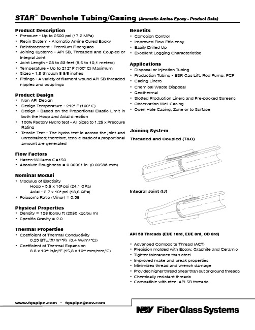
Product Description• Pressure - Up to 2500 psi (17,2 MPa)• Resin System - Aromatic Amine Cured Epoxy • Reinforcement - Premium Fiberglass• Joining Systems - API 5B, Threaded and Coupled or Integral Joint• Joint Length - 28 to 33 feet (8,5 to 10,1 meters)• Temperature - Up to 212° F (100° C) Maximum • Sizes - 1.9 through 8 5/8 inches•Fittings - A variety of filament wound API 5B threaded nipples and couplingsProduct Design• Non API Design• Design Temperature - 212° F (100° C)• Design - Based on the Proportional Elastic Limit in both the Hoop and Axial direction• 100% Factory Hydro test - All sizes to 1.25 x PressureRating• Tensile Test - The hydro test is across the joint and unrestrained; therefore, tensile loads of a proportional amount are generatedFlow Factors• Hazen-Williams C=150• Absolute Roughness = 0.00021 in. (0.00533 mm)Nominal Moduli• Modulus of Elasticity Hoop - 3.5 x 10⁶ psi (24,1 GPa) Axial - 2.7 x 10⁶ psi (18,6 GPa)•Poisson’s Ratio (Minor) = 0.35Physical Properties• Density = 128 lbs/cu ft (2050 kgs/cu m)• Specific Gravity = 2.0Thermal Properties• Coefficient of Thermal Conductivity 0.23 BTU/(ft•hr•°F) (0.4 W/(m•°C))• Coefficient of Thermal Expansion8.8 x 10-6 in/in/°F (15,8 x 10⁻⁶ mm/mm/°C)STAR ™ Downhole Tubing/Casing (Aromatic Amine Epoxy - Product Data)•***************Joining SystemThreaded and Coupled (T&C)Benefits• Corrosion Control• Improved Flow Efficiency • Easily Drilled Up•Excellent Logging CharacteristicsApplications• Disposal or Injection Tubing • Production Tubing - ESP , Gas Lift, Rod Pump, PCP • Casing Liners• Chemical Waste Disposal • Geothermal• Slotted Production Liners and Pre-packed Screens• Observation Well Casing• Open Hole Casing, Zone or to SurfaceAPI 5B Threads (EUE 10rd, EUE 8rd, OD 8rd)• Advanced Composite Thread (ACT)• Precision molded with Epoxy, Graphite and Ceramic • Tighter tolerances than steel• Improved make and break properties • Minimizes thread and wrench damage•Provides higher thread shear than cut or ground threads • Chemically resistant threads• Compatible with steel API 5B threadsIntegral Joint (IJ)23*Manufacturing LocationW = WichitaH = Harbin O = Oman B = Brazil4Joining System InformationAPI THREADED SIZE - Inches1 1/2 2 3/8 2 7/83 1/24 1/2 6 5/88 5/8Thread Type (3)EUE 10rd EUE 8rd EUE 8rd EUE 8rd EUE 8rd OD 8rd OD 8rd Thread Length - in (mm)2.36(59,9) 2.94(74,7)3.25(82,6) 3.50(88,9) 3.88(98,6)4.25(108,0) 4.85(123,2)Make-Up Length Loss - in/jt (mm/jt) 2.06(52,4) 2.56(65,1) 2.88(73,0) 3.13(79,4) 3.50(88,9) 3.88(98,4) 4.50(114,3)Make-Up Torque - ft.•lbs. (N•m)• Optimum 125(170)150(204)185(252)225(306)300(408)500(680)525(714)• Minimum 100(136)125(170)150(204)175(238)250(340)400(544)420(572)• Maximum175(238)225(306)250(340)300(408)450(612)650(884)735(1000)Recommended Make-Up T ool No. 5 Strap No. 11 Strap Approved Power T ongsPin Upset O.D . - in (mm) 2.15(54,6)2.60(66,0)3.10(78,7)3.75(95,3)4.75(120,7)6.65(168,9)7.05(179,1)Handling T oolsElevators T&C (Shoulder Type) - in.(4) 2 3/8 2 7/8 3 1/2 4 1/2 5 1/277 5/8Elevators IJ (Slip Type)(5)MYT MYT MYT YT YC MYT YT Floor Slips (Standard Type) - in.(6) 1 1/2 2 3/8 2 7/8 3 1/2 4 1/2 6 5/87Thread CompatibilityFRP Long vs. Steel Short Form (3)(Extra Threads, Front of FRP Pin)6566767Lubricant Usage (Joints/Gallon)10010010068503426Stretch FactorSeries 1250------4.01(101,9) 2.75(69,9) 1.98(50,3) 1.20(30,4)0.61(15,4)0.66(16,8)(in/per 100 ft) (mm/per 30.5 m)1500--- 3.24(82,4) 2.47(62,6) 1.55(39,3)0.98(25,0)0.48(12,3)0.34(8,6)1750 5.24(133,1) 2.91(73,8) 2.11(53,5) 1.36(34,6)0.87(22,0)------------2000 4.22(107,1) 2.48(62,9) 1.69(43,0) 1.42(36,1)0.75(19,0)------------25003.20(81,2) 2.04(51,8) 1.46(37,2) 1.02(25,8)0.69(17,5)------------T ensile Ultimates (7) psi (MPa)20,000(137,8)35,000(241,3)45,000(310,2)60,000(413,6)90,000(620,5)140,000(965,2)175,000(1206,5)Setting T ension -Refer to NOV Fiber Glass Systems Downhole Tubing Installation and Application Practices - Considerations for Setting Tubing Tension (Anhydride & Aromatic Amine Tubing)Corresponding Numbered Notes:1. Collars - Smaller O.D. collars are available upon request, subject to application approval. Any order for integral joint productsmay include up to 15% threaded and coupled pipe.2. Ratings - All ratings are maximum operating limits. Exceeding these limits will void the warranty on all STAR pipe.3. Threads - All 11/2” EUE 10rd and 2 3/8” - 4 1/2” EUE 8rd API threads conform to API 5B Table 14, 14th Edition (L4 is minimum)and all 5 1/2” - 9 5/8” O.D. 8rd casing threads conform to API 5B, Table 7, 14th Edition (L4 is minimum).4. Elevators T&C - The 1250 & 1500 psi products have smaller OD’s which may work with the same size elevators as the threadsize.5. Elevators IJ - The setting plate must be removed so that the slips will properly set on the fiberglass pipe. Sizing slip typeelevators requires use of the tubing O.D. instead of the upset O.D. on the male end. Rubber setting plates are available to minimize marking and to improve the fit. Shorter bolts are required to hold in place.6. Floor Slips - When running lighter weight (1250-1500 PSI) products, it is good practice to replace the slip dies to make surethey will latch on the pipe body.7. Ultimates- The typical mode of failure for pressure is weep and for tensile it is an across the joint pipe body shear.•***************National Oilwell Varco has produced this brochure for general information only, and it is not intended for design purposes. Although every effort has been made to maintain the accuracy and reliability of its contents, National Oilwell Varco in no way assumes responsibility for liability for any loss, damage or injury resulting from the use of information and data herein nor is any warranty expressed or implied. Always cross-reference the bulletin date with the most current version listed at the web site noted in this literature.© 2015 National Oilwell Varco. All rights reserved.OG8600ENG July 2015Packer Selection (More information listed in “Downhole Tubing and Casing Installation and Application Practices” Manual)• STAR tubing is designed to be set in tension (see stretch chart).• Double Grip Packers are preferred with an on/off tool seal assembly, one-fourth turn release.• Direct Tension Set Packers should be avoided due to the movement of fiberglass.• Direct Set Packers are set <3500 feet deep (1,067 m).• When packer setting is >3500 feet (1,067 m) deep, use steel work string to set packer.• Hydraulic Set Packers are not recommended due touncontrollable forces.• Polished Bore Receptacles are set with proper precautionsto avoid compression. A complete STAR Well Evaluation must be performed to determine the proper set-ups.Perforation• Use a Jet Perforating Gun. Shoot a maximum of two shots at a time at 0° Phase or 180° Phase.• Thread lock all steel to FRP connections.• When installing mixed strings, have one joint of FRP casing supplied without a coupling (pin x pin) for cross-overs.Cementing• Cementing in two stages may help avoid exceeding collapse rating.• Keep differential below external and internal ratings at all times.• Care must be given to avoid shock collapse pressure when setting cement plug.• Fiberglass centralizers are available, metal centralizers must be qualified to fit to FRP .• Cement residue can be cleaned up with proper care using a rock bit.• Landing joints are available, but must be sized for the well-head selected.• Drilling-Up fiberglass tubing or casing is easy with a rock bit(not a mill).Rod Pump Wells• Rod Guides must be used.Electric Submersible Pumps• Care must be given to direction and amount of start-up torque.Fishing• Normal Procedures, Spear or Overshot.Cutting• Mechanical Jet Cutter.North AmericaSouth AmericaEurope Asia PacificMiddle East 17115 San Pedro Ave. Suite 200 Estrada de Acesso á ZonaP .O. Box 6, 4190 CANo. 7A, Tuas Avenue 3 P .O. Box 17324San Antonio, Texas 78232 USA Industrial Portuária de Suape, s/no. Geldermalsen, The Netherlands Jurong, Singapore 639407 Dubai, UAEPhone: 210 477 7500 Recife, PE, Brazil 55.590-000 Phone: 31 345 587 587 Phone: 65 6861 6118 Phone: 971 4881 3566Phone: 55 81 3501 0023。
电缆连接器安装指南说明书
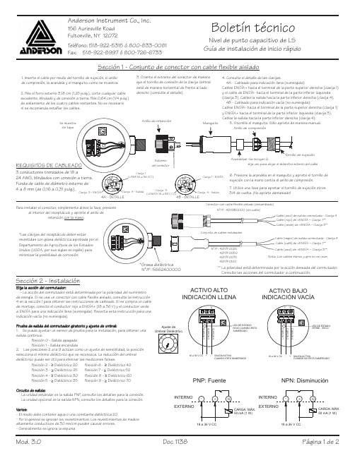
2.P ele el forro externo 3,18cm (1,25pulg.),corte cualquier cable excedente,blindado y de conexión a tierra.P ele 0,64cm (1/4pulg.)de aislamiento de los cuatro cables restantes.No es necesario ni se recomienda estañar los cables.1.Inserte el cable por medio del tornillo de sujeción,el anillo de compresión,la arandela y el manguito,como se muestra.3.Oriente el extremo del conector de manera que el tornillode conexión de la clavija central estéde manera horizontal de frente al lado derecho (consulte el detalle).4.Consulte el detalle de las clavijas.4A -Cableado para indicación llena (sumergida):Cablee ENGÍA+hacia el terminal de la parte superior derecha (clavija 1)y el cable de ENGÍA-hacia el terminal de la parte inferior izquierda (clavija 3).Cablee la salida hacia la parte inferior derecha (clavija 4).4B -Cableado para indicación vacía (no sumergida):Cablee ENGÍA-hacia el terminal de la parte superior derecha (clavija 1)y ENGÍA+hacia el terminal de la parte inferior izquierda (clavija 3).Cablee la salida hacia la parte inferior derecha (clavija 4).5.Atornille el manguito.Sólo apriete de manera manual.6.Presione la arandela en el manguito y apriete el tornillo de sujeción con la mano contra el anillo de compresión.7.Utilice una llave para apretar el tornillo de sujeción otros 3/4de vuelta.¡No apriete demasiado!Extremo del conectorSección 1-Conjunto de conector con cable flexible aisladoNivel de punto capacitivo de LS Guía de instalación de inicio rápidoMod.3.0Doc 11381de 2Página Boletín técnicoAnderson Instrument Co.,Inc.156Auriesville Road Fultonville,NY 12072Teléfono ó:518-922-5315800-833-0081Fax:518-922-8997800-726-6733óP ara instalar el conector,simplemente alinee la llave,presioneal interior del receptáculo y apriete el anillo deretención .con la mano *Las clavijas del receptáculo deben estarrevestidas con grasa dieléctrica aprobada por el Departamento de Agricultura de los Estados Unidos (USDA,por sus siglas en inglés)para minimizar la posibilidad de corrosión.N /P °:5662400000deManguitode sujeciónelija uno para alojar el diámetro externo del cableClavija 1-ENGÍAClavija ENGÍA 318a 36V Salida4-Sección 2-InstalaciónDE ESTADOCUANDO ESTÁCUANDO ESTÁSUMERGIDOACTIVO ALTO INDICACIÓN LLENADE ESTADO -SECOCUANDO NO ESTÁSUMERGIDOACTIVO BAJO INDICACIÓN VACÍAPNP:Fuente18a 36V CC MÁX.(1W)NPN:Disminución18a 36V CCMÁX.(1W)VCC)**La polaridad estádeterminada por la acción deseada del conmutador.Consulte las acciones del conmutador a continuación.Conector con cable flexible aislado (ensamblado)Cable (rojo)de +ENGÍA –Clavija 1**Cable (verde)de +ENGÍA –Clavija 3**N /P °:42119B0000(sin cable)Cable (azul)de salida conmutada Clavija -4-1.1-2.2-206-403-257-504-308-605-359-70--.-La acción del conmutador estádeterminada por la polaridad del suministro de energía.Si se usa un conector con cable flexible aislado,consulte la instrucción 4en la sección 1para obtener las instrucciones de cableado.Si se compra un cable de montaje,conecte el conductor rojo a ENGÍA+(18a 36V)y el conductor verde a ENGÍA para una indicación llena (sumergida).Revierta esta instrucción para una indicación vacía (no sumergida).Se puede ajustar un sensor de prueba para la instalación,para obtener una salida continua:P osición 0-Salida apagada P osición Salida encendidaLas posiciones 2a la 9actúan como un ajuste de sensibilidad,la posición selecciona el mínimo dieléctrico que se reducción del umbral dieléctrico puede ser útil para eliminar las mediciones falsas.P osición Dieléctrico P osición Dieléctrico P osición Dieléctrico P osición Dieléctrico P osición Dieléctrico P osición Dieléctrico P osición Dieléctrico P osición Dieléctrico La unidad estándar es la salida PNP ,consulte los detalles para la conexió unidad opcional es la salida NPN,consulte los detalles para la conexión.El medio debe contener agua o una constante dieléctrica 20P or lo general se ignoran los revestimientos.Los revestimientos de medios altamente conductivos de 30ms/cm pueden causar errores Generalmente se ignora la espuma≥≥≥≥≥≥≥≥Elija la acción del conmutador:Prueba de salida del conmutador giratorio y ajuste de umbral:Circuito de salida:Varios:Ajuste de Conjunto de cables moldeados(negro)de salida conmutada Clavija -4Cable (café)de +ENGÍA –Clavija 1**(azul)de +ENGÍA –Clavija 3**Nota:Los cables blanco y gris no se usan42117F007542117F0100Mod.3.0Doc 11382de 2Página Sección 3-EspecificacionesEspecificaciones de operación y medioambientalesLímites de temperatura ambiente Clasificación de presión 10barias (150PSI)máximo Límites de temperatura de proceso:0a 100C (32a 212F)Limpieza en el lugar 150ºC (302ºF)máximo 60minutosFunción El cableado determina si laseñal es llena o vacíaTiempo de respuesta 0,1seg.Umbral dieléctrico mínimo Seleccionable de 20a 70Especificaciones eléctricas Requisitos de voltaje Consumo de energía Tipo de 0,6W (es decir,de 25mAa 24V CC)Salida de señal Suministro (activo de 50mA)NPN opcional:Disminución (máximo de 50mA)Energía de transmisión de señal Conexión Un conector eléctrico micro miniM12de 3clavijas (RDR)°°PNP::14a 140F)::::::18a 36V CC (20mA):::1mw :°≤≤-10a 60C (°Especificaciones mecánicas Materiales bañados Acero inoxidable 316L,PEEK Acabado bañado Superior a Ra =32Material de la cubierta Cubierta,tapa y conexión roscada deacero inoxidable de serie 300(superficies que no son de contacto).Protección de caja Aprobación de agencia Cumple las normas CE Cumple las normas 3-A,verificado terceros de acuerdo con la norma 74-03Indicador visualIndicador LED de estado Rojo:Sonda sumergidaVerde:Sonda en seco Garantía:2añospor ::::NEMA 4X,IP69K :;:ATENCIÓN:CABLEADO DEL CONECTORClavija Salida de conmutador MÁX.50mAClavija Clavija 1-18a 36V CC V CC Com 3-V CC Com 18a 36V CC 4-Consulte un boletín técnico para obtener información sobre los códigos de color de Anderson.Ind.llena Ind.vacíaEXTREMO DE SENSORCLAVIJA 3CLAVIJA 1CLAVIJA 4lb)mm pulg.)。
电缆工具使用说明书

电缆工具使用说明书一、工具概述电缆工具是在电力工程、通信工程、建筑工程等领域中常用的装配和维修工具,用于安装、连接和维护电缆及其附件。
本使用说明书旨在帮助用户正确、安全地使用电缆工具,提高工作效率,并确保人身安全和设备完整。
二、安全须知1. 在使用电缆工具之前,请仔细阅读并理解本说明书,并遵守相关安全操作规程。
2. 使用电缆工具时,请佩戴适当的防护装备,如安全帽、防护眼镜、防护手套等。
3. 严禁未经许可擅自修改、拆解电缆工具,任何故障需由专业维修人员检修。
4. 在使用电缆工具期间,如发现任何异常情况,请立即停止使用,并及时报修。
三、常见电缆工具及使用方法1. 剥线剪剥线剪是常用的电缆工具之一,用于剥离电缆绝缘层和护套层。
使用时,将电缆放入剪刀口中,在适当的力道下剪断绝缘层,然后在剪刀刀口处用力旋转,将绝缘层剥离。
2. 铜铝焊接夹具铜铝焊接是电力工程中常见的连接方式,铜铝焊接夹具用于夹持铜铝焊接区域,确保焊接时的稳定性。
夹具的使用方法简单,将夹具固定于焊接区域,通过旋转紧固螺丝来夹紧铜铝。
3. 电缆扳手电缆扳手用于紧固和拆卸电缆连接头。
使用时,将扳手套住连接头并旋转,通过扳手的力臂原理来施加或解除扭矩。
4. 电缆剥皮钳电缆剥皮钳用于在电缆维护和故障排除过程中剥离电缆绝缘层和护套层。
使用时,将剥皮钳功能头套在电缆上,通过剥皮钳的开合来剥离绝缘层和护套层。
5. 电缆检测仪电缆检测仪用于检测电缆的绝缘状态、电压和电阻等参数。
使用时,请确保电缆检测仪的电源充足,并按照仪器使用说明正确连接电缆。
四、故障排除1. 若在使用电缆工具过程中发生电流泄漏、电缆断裂等故障,请立即停止使用,并报告维修人员进行维修。
2. 每次使用电缆工具后,请进行清洁、保养,确保工具的功能良好。
五、维修与保养1. 电缆工具的维修和保养应由专业人员进行,严禁未经训练的人员擅自进行修理。
2. 定期对电缆工具进行检查,确保工具的刀刃锐利、结构完整,并进行必要的润滑。
LBG2-315(400)6 矿用隔爆型高压电缆连接器

额定峰值 耐受电流
(KA)
10 15.75
额定短时 耐受电流
(KA)
4 6.3
插头与插座 间插拔力(N)
配用电缆 最大外径
(mm)
30~80
78
30~80
88
1
该连接器是由以导电杆为公用连接件的两段完全相同的部分组成,每一部分又包括电缆引入系统和 接线座及绝缘件等。绝缘件选用性能优良的绝缘材料(DMC)压制而成,上面的电缆主芯线孔设计成流 线型的喇叭口,从而简化了屏蔽电缆及接地电缆的接线方法,同时,绝缘件的整体与外壳的联接采用了 内部固定方式,避免了与外界的连通。联接器内部带电体对地之间的电气间隙大于 60mm,爬电距离大 于 90mm。
(9)各主线芯上包绕 1~2 层自粘带,以增强绝缘性。对于监视线,接地线的根部(如图 3 所 示 ), 也须包绕 1~2 层自粘带,以增强与环氧浇铸剂的粘合,提高密封性。
(10)将电缆末端朝上竖起,在外护套末端 15mm 处(见图 2)做个记号,然后把套在电缆护层上的 塑料模固定在电缆上,与此同时把套入模壳内的主线芯,监视线芯及接地线芯适当分布均匀。
2.连接器通常作为各种防爆高压开关的电缆引入装置,供普通型或 UGSP 监视屏蔽型电缆在移动变 电站供电时接线之用。它既可以在电缆段上两端连接用,以便互相插接。也可以将其一半专用防爆联接 部位直接接到移动变电站上。
二、使用环境
连接器使用于下列工作环境: 1. 海拔高度不超过 1000 米; 2. 周围环境温度为-20℃~+40℃; 3. 周围空气相对湿度不大于 95%(+25℃); 4. 有瓦斯、煤尘等爆炸性危险环境的矿井中; 5. 无摇动和冲击振动的地方; 6. 安装类别:Ⅲ类; 7. 污染类别:3 级。
电缆接续机说明书

电缆接续机说明书一. 概论本手册是针对目前在市话线路施工中遇到的接续技术问题而编集而成。
目的是使电缆接线人员在施工维护中对个方面所应注意的问题有较深入的理解,提高工作效率,提高接续质量。
二、电缆在通讯电缆的使用当中,全塑电缆将逐步取代传统的铅包纸绝缘电缆。
全塑电缆的优越性能使它在世界各地的电话局,电信单位及施工单位得到广泛的应用,而其中全色谱的市话全塑电缆应用得更为广泛。
全色谱是根据国际电工委员会的标准而定,它的颜色组成为十种颜色(白、红、黑、紫及蓝、桔、绿、棕、灰)的二十五种配搭。
A.白白白白白红红红红红黑黑黑黑黑黄黄黄黄黄紫紫紫紫紫B.蓝桔绿棕灰蓝桔绿棕灰蓝桔绿棕灰蓝桔绿棕灰蓝桔绿棕灰电缆芯线的几个偶大致可分为:25对(或12+18)为一小组;100对(或50+50)为一色带组;每一百对芯线均有不同色标带显示,以资区别,在接续时,可按照芯线外缠绕的色标来进行线序分别,以免错接。
三、接线子和模块目前的全塑色谱电缆的接续方法主要为以下两种:1.单体接续子--按不同规格及要求使用不同的接线子可接续两根至三根电缆芯线,主要接线子型号有:UY:黄色盖、接两根0.4-0.7mmΦ的全塑芯允。
UY2:双刀片、黄色盖、接两根0.4-0.9mmΦ的全塑芯线。
UR:红色盖、接两根至三根0.4-0.9mmΦ的全塑芯线。
UB:蓝色盖分接接线子,可在一根直通的芯线(0.4-0.7mmΦ)上分接一根0.4-0.7mmΦ的全塑芯线。
UP2及UP3分别是UY及UR的变体,为白色上盖,适用于干燥环境中接续纸绝或全塑芯线。
2.MS2式模块接续——MS2模块把单体接线子的特点集中在一个集合式的接续模块中,在每一个模块中可同时接续二十五对芯线。
模块(MS2)在应用上可分为以下几个主要型号:4000D型——是一种直接型的模块,带有浅黄色上盖、浅、深黄二色主体及深黄色的底座。
4008D型——半分接模块,主体下部芯线在压接时不予去除,一般应用与新老局或设备割接是不干扰老线路童话情况下使用。
电缆接线器产品说明书

Eaton 199077Eaton Moeller® series Rapid Link - DOL starter, 6.6 A, Sensor input 2, 230/277 V AC, AS-Interface®, S-7.A.E. for 62 modules, HAN Q4/2, with manual override switchGeneral specificationsEaton Moeller® series Rapid Link DOL starter199077RAMO5-D202A32-412RS14015081971350120 mm 270 mm 220 mm 1.8 kgIEC/EN 60947-4-2 CE UL approval CCC RoHS UL 60947-4-2Assigned motor rating: for normal internally and externally ventilated 4 pole, three-phase asynchronous motors with 1500 rpm at 50 Hz or 1800 min at 60 HzProduct NameCatalog NumberModel CodeEANProduct Length/Depth Product Height Product Width Product Weight Certifications Catalog NotesIs the panel builder's responsibility. The specifications for the switchgear must be observed.3 kW6.6 A (at 150 % Overload)480 V AC, 3-phase400 V AC, 3-phase10000 A0 VMeets the product standard's requirements.Is the panel builder's responsibility. The specifications for the switchgear must be observed.Does not apply, since the entire switchgear needs to be evaluated.0 kW2.238 kWMeets the product standard's requirements.0 V-40 °CKey switch position HANDKey switch position AUTOKey switch position OFF/RESETThermistor monitoring PTC Generation change RAMO4 to RAMO5Generation change from RA-MO to RAMO 4.0Electromagnetic compatibility (EMC)Generation Change RA-SP to RASP5Connecting drives to generator suppliesGeneration change from RA-SP to RASP 4.0Generation Change RASP4 to RASP5Configuration to Rockwell PLC for Rapid LinkRapid Link 5 - brochureDA-SW-USB Driver DX-COM-STICK3-KITDA-SW-drivesConnectDA-SW-Driver DX-CBL-PC-3M0DA-SW-drivesConnect - InstallationshilfeDA-SW-drivesConnect - installation helpDA-SW-USB Driver PC Cable DX-CBL-PC-1M5DA-SW-drivesConnect USB Driver DX-COM-PCKITMaterial handling applications - airports, warehouses and intra-logisticsProduct Range Catalog Drives EngineeringDA-DC-00004523.pdfDA-DC-00003964.pdfDA-DC-00004184.pdfDA-DC-00004525.pdfeaton-bus-adapter-rapidlink-reversing-starter-dimensions-002.eps eaton-bus-adapter-rapidlink-speed-controller-dimensions-002.eps eaton-bus-adapter-rapidlink-speed-controller-dimensions-003.eps eaton-bus-adapter-rapidlink-reversing-starter-dimensions-003.epsETN.RAMO5-D202A32-412RS1.edzIL034084ZU10.11 Short-circuit ratingRated operational power at AC-3, 380/400 V, 50 HzInput currentRated operational voltageRated conditional short-circuit current, type 1, 480 Y/277 V Rated control supply voltage (Us) at AC, 50 Hz - min10.4 Clearances and creepage distances10.12 Electromagnetic compatibility10.2.5 LiftingRated power at 575 V, 60 Hz, 3-phaseRated power at 460 V, 60 Hz, 3-phase10.2.3.1 Verification of thermal stability of enclosures Rated control supply voltage (Us) at DC - minAmbient storage temperature - minFitted with:Application notes BrochuresCatalogs Certification reportsDrawingseCAD model Installation instructions Installation videosThermo-clickManual override switchElectronic motor protectionTwo sensor inputs through M12 sockets (max. 150 mA) for quick stop and interlocked manual operationShort-circuit releaseAC-53a0 VCenter-point earthed star network (TN-S network)AC voltagePhase-earthed AC supply systems are not permitted.Is the panel builder's responsibility.Class 10 A10 kA230/277 V AC -15 % / +10 %, Actuator for external motor brake 55 °C0 kW< 95 %, no condensationIn accordance with IEC/EN 50178Parameterization: drivesConnect mobile (App) Parameterization: KeypadParameterization: drivesConnectParameterization: FieldbusDiagnostics and reset on device and via AS-Interface Rapid Link 5MN040003_ENramo5_v5.dwg ramo5_v5.stpOverload cycleNumber of pilot lightsRated control supply voltage (Us) at AC, 50 Hz - max System configuration type10.8 Connections for external conductorsCoordination class (IEC 60947-4-3)Rated conditional short-circuit current, type 1, 600 Y/347 V Rated conditional short-circuit current (Iq)Braking voltageAmbient operating temperature - maxRated operational power at AC-3, 220/230 V, 50 Hz Climatic proofingFeaturesLifespan, electrical Manuals and user guides mCAD model10,000,000 Operations (at AC-3)Number of command positions1Electrical connection type of main circuitPlug-in connectionElectrical connection type for auxiliary- and control-current circuit Plug-in connectionRated control supply voltage (Us) at DC - max0 V10.9.3 Impulse withstand voltageIs the panel builder's responsibility.Braking current≤ 0.6 A (max. 6 A for 120 ms), Actuator for external motor brakeAmbient operating temperature - min-10 °C10.6 Incorporation of switching devices and componentsDoes not apply, since the entire switchgear needs to be evaluated.Current limitationAdjustable, motor, main circuit0.3 - 6.6 A, motor, main circuitCable length10 m, Radio interference level, maximum motor cable length10.5 Protection against electric shockDoes not apply, since the entire switchgear needs to be evaluated.Mounting positionVerticalMains switch-on frequencyMaximum of one time every 60 secondsClassCLASS 10 A10.13 Mechanical functionThe device meets the requirements, provided the information in the instruction leaflet (IL) is observed.10.2.6 Mechanical impactDoes not apply, since the entire switchgear needs to beevaluated.10.9.4 Testing of enclosures made of insulating materialIs the panel builder's responsibility.10.3 Degree of protection of assembliesDoes not apply, since the entire switchgear needs to be evaluated.Electromagnetic compatibilityClass AVoltage typeDCProduct categoryMotor starterOverload release current setting - min0.3 ARated control voltage (Uc)24 V DC (-15 %/+20 %, external via AS-Interface® plug)230/277 V AC (external brake 50/60 Hz)Rated operational current (Ie)6.6 AAssigned motor power at 460/480 V, 60 Hz, 3-phase3 HPRated frequency - min47 HzNumber of auxiliary contacts (normally closed contacts)Rated conditional short-circuit current (Iq), type 2, 380 V, 400 V, 415 V0 APower consumption8 W10.2.3.2 Verification of resistance of insulating materials to normal heatMeets the product standard's requirements.10.2.3.3 Resist. of insul. mat. to abnormal heat/fire by internal elect. effectsMeets the product standard's requirements.On-delay20 - 35 msLifespan, mechanical10,000,000 Operations (at AC-3)Rated operational current (Ie) at 150% overload6.6 AProtocolAS-Interface profile cable: S-7.4 for 62 modulesASIOverload release current setting - max6.6 A10.9.2 Power-frequency electric strengthIs the panel builder's responsibility.Overvoltage categoryIIIDegree of protectionNEMA 12IP65Rated frequency - max63 HzVibrationResistance: 6 Hz, Amplitude 0.15 mmResistance: According to IEC/EN 60068-2-6Resistance: 10 - 150 Hz, Oscillation frequency Resistance: 57 Hz, Amplitude transition frequency on accelerationRated operational power at 380/400 V, 50 Hz - max3 kWAmbient storage temperature - max70 °CShort-circuit protection (external output circuits)Type 1 coordination via the power bus' feeder unit, Main circuitRated control supply voltage (Us) at AC, 60 Hz - min0 V10.7 Internal electrical circuits and connectionsIs the panel builder's responsibility.Rated impulse withstand voltage (Uimp)4000 VConnectionConnections pluggable in power sectionOff-delay20 - 35 ms10.10 Temperature riseThe panel builder is responsible for the temperature rise calculation. Eaton will provide heat dissipation data for the devices.FunctionsFor actuation of motors with mechanical brakeExternal reset possibleTemperature compensated overload protectionOutput frequency50/60 HzMains voltage tolerance380 - 480 V (-15 %/+10 %, at 50/60 Hz)Rated conditional short-circuit current (Iq), type 2, 230 V0 AInterfacesMax. total power consumption from AS-Interface® power supply unit (30 V): 190 mASpecification: S-7.A.E. (AS-Interface®)Number of slave addresses: 62 (AS-Interface®)TypeDOL starter10.2.2 Corrosion resistanceMeets the product standard's requirements.Supply frequency50/60 Hz, fLN, Main circuit10.2.4 Resistance to ultra-violet (UV) radiationMeets the product standard's requirements.10.2.7 InscriptionsMeets the product standard's requirements.Rated control supply voltage (Us) at AC, 60 Hz - max0 VRated operational current (Ie) at AC-3, 380 V, 400 V, 415 V6.6 ARated operational power at 380/400 V, 50 Hz - min0.09 kWModelDirect starterNumber of auxiliary contacts (normally open contacts)Eaton Corporation plc Eaton House30 Pembroke Road Dublin 4, Ireland © 2023 Eaton. All Rights Reserved. Eaton is a registered trademark.All other trademarks areproperty of their respectiveowners./socialmedia15 g, Mechanical, According to IEC/EN 60068-2-27, 11 ms, Half-sinusoidal shock 11 ms, 1000 shocks per shaft Max. 2000 mAbove 1000 m with 1 % performance reduction per 100 m Max. 1000 mShock resistanceAltitude。
高压电缆连接器资料大全

高压电缆连接器资料大全从最的需求来看,高压电缆连接器仍是我们机械界炙手可热的产品,为此在这里整理了一些资料,分享给广大网友们。
高压电缆连接器产品介绍高压电缆连接器适用于煤矿井下采煤掘进巷道中联接1140V,10kV电力电缆电路。
可供UGSP监视屏蔽型各种橡套电缆在移动变电站供电时接线之用,可以在电缆上两端连接用,以便互相插接,也可将其一半防爆连接部位接到移动变电站上sl。
高压电缆连接器特点1(该连接器是由导电杆为公用连接件的两段完全相同的部分组成,每一部分又包括电缆引入系统和接线座及绝缘子;2(用于防止电缆拔脱的压板设计成带有弧形沟槽的铸件,提高了压线的可靠性; 3(绝缘子选用了性能优良的绝缘材料(DMC)压制而成;4(绝缘子的整体与外壳的联接采用内部固定方式,避免了与外界的连通。
高压电缆连接器维护保养1、使用与维护过程中,应防止隔爆面碰撞或锈蚀。
2、在维修过程中连接器严禁带电操作,在断电后必须确保无残余电压时方可拔开和拆卸任何部位,残余电荷除按照煤安规程用可靠手段放电外,也可以利用移动电站衰减放电,其操作顺序如下:2.1、一般在操作前负荷开关保持合闸,拉开高压开关并加以“不许合闸”标志或加以锁闭,然后操作连接器,如有由低压反馈可能应先拉开馈电开关及负荷开关。
2.2、如拉高压开关时负荷开关已断开,在拉开高压开关前加以标志或锁闭后,先将负荷开关闭合至少一分钟,使残余电压放泄完以保证安全,再进行必要操作。
2.3、装回时必须全线插接完后再行送电。
2.4、将连接器中间壳体之法兰拔开后,如须保持一段时间应用封盖子盖好,仍用密封垫圈密封,以防潮气入侵。
高压电缆连接器的分类LBG-500高压电缆连接器LBG1-200高压电缆连接器LBG1-400高压电缆连接器LBG1-315高压电缆连接器零插入力直形电缆连接器除些之外,矿用隔爆型高压电缆连接器也是应用比较广泛的LBG1-500/3300矿用隔爆型高压电缆连接器 LBG2-630/3300矿用隔爆型高压电缆连接器 LBG3-500/300矿用隔爆型高压电缆连接器 LBG4-630/10矿用隔爆型高压电缆连接器 LBG5-500/6矿用隔爆型高压电缆连接器 LBG6-800/3300矿用隔爆型高压电缆连接器 LBG7-800/3300矿用隔爆型高压电缆连接器 LBD1-350/1140矿用隔爆型电缆连接器 LBD2-100/1140矿用隔爆型电缆连接器 LBD3-315/127矿用隔爆型电缆连接器 LBD4-100/1140矿用隔爆型电缆连接器 LBD5-25/250矿用隔爆型电缆连接器 LBD6-250/1140矿用隔爆型电缆连接器 LBD7-630/1140矿用隔爆型电缆连接器 LD11-250/1140电缆连接装置LBD8-500/1140矿用隔爆型电缆连接器这里有这几种连接器供大家选择,这些信息均来自于各大网站以及自己搜集。
(整理)GPZB-I高压保护器使用说明书.
GPZB-I微电脑智能综合保护装置说明书济源市维创自动化科技有限公司目录1 系统综述 (3)1.1 系统概述 (3)1.2 系统特点 (3)1.3 系统构成 (4)2 产品特点 (5)3 技术指标 (5)3.1 工作环境要求 (5)3.2 功率消耗 (5)3.3 主要保护功能配置 (5)4 保护原理 (6)4.1 速断保护 (6)4.2 零序过流保护 (6)4.3 过电压保护 (7)4.4 过载反时限保护 (7)4.5 低电压保护 (8)4.6 绝缘监视保护 (9)4.7 三相不平衡 (9)5 人机对话操作说明 (9)5.1 人机对话简介 (9)5.2 主菜单说明 (10)5.3 测量数据 (11)5.4 定值整定 (12)5.5 保护功能整定及解释 (12)5.6 密码管理 (16)5.7 事件查询 (17)5.8 试验项目 (17)5.9 附加功能 (18)5.10 出厂设置 (20)6 关于B相电流 (20)6.1 只对开关A相通电流 (21)6.2 只对开关C相通电流 (21)6.3 A相、C相同时通电流(接线方式1) (22)6.4 A相、C相同时通电流(接线方式2) (22)7 关于485通讯 (23)8 关于CAN通讯(选配) (23)9 用户安装调试、维护说明 (23)注意事项 (23)10 常见故障排查 (24)11 航插(26芯)引脚说明 (24)附件:产品接线图1、系统综述1.1 系统概述煤矿井下高压供电系统线路短、多级变电所级联,高压供电线路的布线特点使得常规继电保护装置不能通过整定值和时间级差的方式有选择的跳开故障点开关,出现“越级跳闸”问题。
我们根据煤矿井下高压供电线路的实际情况,采用全系统智能零时限防越保护方式,以辐射型高速通讯网络实现上下级继电保护装置的配合,为井下的高压供电系统的每台高爆开关提供可靠、全时、动态、高速的防越信息通道,每一台开关不再独立运行,而是以相同的节拍成为防越保护系统一部分,基于全站的防越保护系统提高了高压供电线路的可靠性和故障动作时间的实时性。
(1)LBG1-200.400高压电缆连接器说明书
十、
10.1
开箱后应检查产品是否与用户所定购的产品相符、产品合格证、使用说明书等重要文件。
额定电流(A)
极限通过电流
动热稳定电流
配用电缆
最大外径mm
有效值
峰值
热稳定
2秒
动稳定
2秒
橡套
LBG1-200/6
6
200
9千安
15千安
3.15千安
7.875千安
78
LBG1-400/6
6
400
9千安
15千安
6.3千安
14千安
78
LBG1-200/10
10
200
9千安
15千安
3.15千安
7.875千安
2.1.2接线装置为无缝钢管制造的中壳及螺栓固定于内腔的绝缘件组成。
2.1.3可动接触部分由装于绝缘件内的铜接线座、铜接线管(GT型外购件)、铜插座及接触杆组成;连接器在接触杆处分成各包有上述三部分的两段,接触杆为两段公用的连接装置;壳体外有铭牌,警告牌及防爆标志。
三、
3.1
表1
型 号
额定电压(kV)
5.2.18在连接器的绝缘体孔内全部插上接触杆,然后把另一段电缆的连接器插上,须注意不要漏掉中壳法兰面上的密封垫圈,并装好螺栓。
5.2.19当两个连接器相连成一个完整的连接器,并接入运行线路必须将连接器两端的外接地桩可靠接地,在井下应与下接地网可靠连接。
高压连接器技术规格书 (2)

高压连接器技术规格书一、设备的使用条件海拔高度不超过2000米;周围环境压力为80kPa〜I1OkPa。
周围环境温度T0℃〜+4(TC0相对湿度不大于95⅝(25o C)o在有爆炸性气体(甲烷混合物)的矿井中。
无破坏金属和绝缘材料的腐蚀性气体的场所。
二、设备名称数量名称:BHG2-2G400/6矿用隔爆型高压电缆接线盒三、技术要求(一)功能描述1.产品适用于在交流50Hz、额定电压6KV供电网络中,供动力设备供电电缆的连接和分支作用。
2.接线盒呈圆筒形,采用上下开盖形式。
主要由上盖、主腔体、高压陶瓷接线柱、辅助接地端子、内外接地装置、电缆引入装置等部分组成。
3,接线盒设计合理,电气间隙、和爬电距离设计符合规范,要满足6KV供电系统使用要求。
4.防爆面要采用可靠的磷化处理,配带的所有螺栓必须为镀锌型。
5.所有配套的金属抗圈、挡板的厚度不小于2mni。
(二)设备技术参数1.额定电流:400A2.额定电压:6KV3.额定短时耐受电流:6.3KA4.额定峰值耐受电流:15.75KA5.接线盒的防爆型式为矿用隔爆型,防爆标志EXdI。
(三)主要部件材质和寿命优质钢铸件隔爆外壳。
四、供货范围BHG2-2G400/6矿用隔爆型高压电缆接线盒10只,随机应有详细的与产品配套的使用维护说明书、产品合格证、及国家权威部门颁发的煤安证,防爆合格证;提供10套完整的书面安装维护使用说明书和一套电子版安装维护使用说明书。
五、设备制造和检验标准1.产品应符合《煤矿安全规程》2016版要求;符合GB3836-2010《爆炸性气体环境用电气设备》标准要求;产品的其他性能要求必须符合相应的国家和行业标准。
2,符合MT/T1100-2009煤矿用隔爆型电缆接线盒,符合Q/DG851-2013矿用隔爆型高压电缆接线盒3.本技术规格书未充分引述有关标准和规范的条文,卖方应保证提供符合本技术规格书和工业标准的优质产品。
六、质保设备的质量保证期为12个月。
LBG2-315(400)6 矿用隔爆型高压电缆连接器
二、使用环境
连接器使用于下列工作环境: 1. 海拔高度不超过 1000 米; 2. 周围环境温度为-20℃~+40℃; 3. 周围空气相对湿度不大于 95%(+25℃); 4. 有瓦斯、煤尘等爆炸性危险环境的矿井中; 5. 无摇动和冲击振动的地方; 6. 安装类别:Ⅲ类; 7. 污染类别:3 级。
参考示意图:
高压开关
连接器
移动变电站 负荷开关变压器馈电开关
(2)若操作时负荷开关已断开,则拉开高压开关,并加以锁闭或加挂“不许合闸”标志,先将负 荷开关闭合至少 1 分钟,使残余电压放泄完,然后在进行必要操作,以保证安全。
(3)装回时必须全线插接完后再行送电。 2.连接器中间壳体的法兰拆开后,如须保持一段时间,必须应封端盖子盖好,并用密封垫圈密封, 以防潮气侵入。 3.橡套电缆的安装工作可在井下进行,其安装工艺应按照以下要求进行。 (1)首先检查电缆的型号、规格是否与所安装的连接器相符并备齐各种器材,连接器及各种器材 必须保持清洁(尤其是连接器里的绝缘件,必须在安装前擦干净),施工现场应尽可能注意清洁。 (2)把压紧法兰盘、封环、密封垫圈、接线腔以及塑料模壳(用于浇灌环氧冷铸剂)先后套进电 缆。 (3)按图 2 规定尺寸,在电缆末端 250mm 长度上剥去电缆护套及护套下监视线内外的半导体层, 松开留下的监视线,并编成二根辨子股,然后在它上面在套上绝缘管。绝缘管尽量套到辫子股的根部, 绝缘管的另一端应露出导线 28mm 长。 (4)用木锉、砂皮及四氯化碳溶剂擦去监视线下面的内护套根部表面 22mm 长度的残留半导体胶, 然后安图 2 规定尺寸将 22mm 长度以外的内护套(包括内护套里面的填充物)全部剥去,并用 J-20 型丁 基自粘胶带(以下简称自粘带)22mm 长度的内护套上包绕 2 层,自粘带绕包时,注意将自粘带拉伸 100%+200%左右在进行绕包。 (5)将内护套下面的接地线松开并编成二根辨子股,然后套上绝缘管,露出导线 28mm 长。 (6)按图 2 规定尺寸,切去各主线芯端部绝缘 28mm 长(包括绝缘内外的半导体层)。
高压电缆连接器技术规格书

矿用隔爆型高压电缆连接器技术规格书一、使用条件环境温度:-10℃〜+40。
C(煤矿井下);大气压力:80kpa"116kpa;空气相对湿度不大于95%(25℃);有甲烷混合气体和煤尘,且有爆炸危险的矿井。
二、名称数量1、名称:矿用隔爆型高压电缆连接器,参考型号:1BG1-500/33002、需求数量:按计划数量。
三、技术要求1、功能描述:可与引进设备开关箱、组合开关、负荷开关及国产大功率开关等设备引接配套使用。
在交流3.3kv、频率50HZ线路中,作为组合开关、采煤机、顺槽开关、电机、移变等电源进线、出线、电缆与电缆终端间的耦合连接装置,连接器分别由插头部份、插座部份及中间连接器三个主体组成,具有绝缘性能高、插接快捷、操作方便、灵活可靠等特点。
2、主要技术参数:(1)防爆标志:ExdI(2)额定电压:3300V(3)额定电流:500A(4)允许引入最大电缆外径:不小于①83.6mm;(5)连接器壳体采用精密铸铜铸造而成,具有耐腐蚀等特点。
(6)绝缘件选用了性能优良的绝缘材料压制而成;同时绝缘件的整体与外壳的联接采用内部固定方式。
四、供货范围矿用隔爆型高压电缆连接器(按计划数量)件,每套随机提供产品说明书、矿用产品安全标志、防爆合格证、产品合格证书面版各一份,电子版资料一份。
五、设计、制造和检验标准1、防爆性能符合GB3836-2010中有关规定要求;2、符合MT/T947-2005《矿用隔爆型高压电缆连接器》及行业最新相关标准。
六、质保期质量保证期为12个月,从产品投用后算起。
在质量保证期内,对于非买方原因造成的故障,供应商负责免费提供维修服务。
技术负责人:制:。
钢管连接电压开关产品说明书

Operating Pressure Data
Adjustable Range Number
Adjustable Set Point Range
Increasing
Decreasing
Deadband (approximate)
Maximum Recommended System Pressure
Proof Pressure
1
5 to 75
2.3 to 72.3
2.7
2
15 to 150
9 to 144
6
4
50 to 300
36 to 286
14
5
125 to 600
100 to 575
25
7
500 to 1500
440 to 1440
60
8
800 to 2800
675 to 2675
125
All values given in psig.
Ordering Procedure
Example
When factory presetting is desired, stipulate set point, increasing or decreasing
Insert available option number or letter designation as required
AER0935_1 7/13 Specifications and dimensions subject to change.
600 3000 3000 3000 3000 3000
1000 5000 5000 5000 5000 5000
Standard Specifications
- 1、下载文档前请自行甄别文档内容的完整性,平台不提供额外的编辑、内容补充、找答案等附加服务。
- 2、"仅部分预览"的文档,不可在线预览部分如存在完整性等问题,可反馈申请退款(可完整预览的文档不适用该条件!)。
- 3、如文档侵犯您的权益,请联系客服反馈,我们会尽快为您处理(人工客服工作时间:9:00-18:30)。
开箱后检查产品在运输过程中外观是否有明显的裂缝或损坏。
十一、注意事项
使用前应检查产品出厂电压与实际使用电压是否相符,并核对其它主要技术参数。
十二、警示语句
-“严禁带电开盖”必须断电后开盖。
5.2
5.2.1安装前首先检查电缆的型号、规格是否与所安装的连接器相符并齐各种器材,连接器及各种器材必须保持清洁(尤其是连接器里的绝缘件,必须在安装前擦清洁);施工现场应尽可能注意清洁。
5.2.2把压紧法兰盘、封环、压线腔、密封圈连接腔以及塑料模壳(用于浇灌环氧冷铸剂),先后套进电缆。
5.2.3按图1规定的尺寸,在电缆末端250mm长度上剥去电缆护套及护套下监视线内外的半导体层,松开留下的监视线,并编成二根辫子股,然后在它上面再套上绝缘管;绝缘管应尽量套到辫子股的根部,绝缘管的另一端应露出导线28mm长。
六、
核对电压等级及相关技术参数无误后,才可以送电进行调试。
七、
故障现象
原因分析
排除方法
备注
电缆松动
没有可靠固定
检查连接是否可靠固定并保持规定的电气间隙和爬电距离
8.1
8.1.1使用与维护过程中,应防止隔爆面碰撞或锈蚀。
8.1.2 在维修过程中连接器严禁带电操作,在断电后必须确保无残余电压时方可拔开和拆卸任何部位,残余电荷除按照煤安规程用可靠手段放电外,也可以利用移动电站衰减放电,其操作顺序如下:
5.2.5将内护套下面的接地线松开并编织成二根辫子股,然后再套上绝缘管,并露出导线28mm长。
5.2.6按图1规定的尺寸切去各主线芯端部绝缘28mm长(包括绝缘内外的半导体层)。
5.2.7按图1尺寸剥去各主线芯绝缘外面190mm长度上的半导体层,并用木锉、砂皮、四氧化碳溶剂仔细擦去主线芯绝缘表面上的残留半导体胶。
十一、注意事项.............................................................................5
十二、警示语句.............................................................................5
1.3
1.3.1海拔高度不超过1000米,周围环境温度-20℃~+40℃时。
1.3.2周围空气相对湿度不大于95%(+25℃时)。
1.3.3在有甲烷和煤尘爆炸性混合气体的矿井中。
1.3.4在无强烈颠簸振动、无滴水及水浸入的环境中。
1.3.5在无足以破坏金属和绝缘的腐蚀性气体及蒸气集中的地方。
1.4
L B G 1–□ / □
5.2.8当电缆的另一端亦完成上述工序后,应测量各主线芯绝缘电阻及监视线对接地线之间的绝缘电阻,测量仪器分别采用2500V、500A欧姆表,对于新电缆要求各主线芯绝缘电阻及监视线对接地线之间绝缘电阻应符合出厂指标。
5.2.9在各主线芯上包绕1-2层自粘带,以增强绝缘性,对于监视,接地线的根部(如图2所示),亦须包绕1-2层自粘带,以增强与环氧浇铸剂的粘合,提高密封性。
额定电压(V)
额定电流(A)
设计序号
高压
矿用隔爆型
连接器
1.5
1.5.1本系列产品符合MT/T947-2005《矿用隔爆型高压电缆连接器》标准中的要求。
1.5.2符合GB3836-2000《爆炸性气体环境用电气设备》标准要求。
1.6
矿用隔爆型;防爆标志:ExdI。
二、
2.1
2.1.1电缆固定引线装置,由压紧法兰盘、压板、垫圈、封环和无缝钢管(或钢板)焊接外壳及内外接地组成。
图1连接器电缆端部剥切尺寸
5.2.4用木锉、砂皮、四氧化碳溶剂擦去监视线下面的内护套根部表面22mm长度上的残留半导体胶,然后按图1规定尺寸将22mm长度以外的内护套(包括内护套里面的填充物)全部剥去,并用J-20型丁基自粘性胶带(以下简称自粘带)22mm长度的内护套上包绕2层,自粘带绕包时,注意将自粘带拉伸100%-200%左右再进行绕包。
三、产品主要技术参数.......................................................................1
四、尺寸、重量.............................................................................2
5.2.18在连接器的绝缘体孔内全部插上接触杆,然后把另一段电缆的连接器插上,须注意不要漏掉中壳法兰面上的密封垫圈,并装好螺栓。
5.2.19当两个连接器相连成一个完整的连接器,并接入运行线路必须将连接器两端的外接地桩可靠接地,在井下应与下接地网可靠连接。
5.2.20已剥开的电缆芯线要绞紧(最好能搪锡或用GT型铜连接管绞紧芯线),然后用压钳压紧再放入铜接线座内,用内六角圆柱紧定螺钉牢固地与接线桩接好。
五、产品使用、操作方法.....................................................................2
六、参数设定及调试.........................................................................4
8.1.2.3装回时必须全线插接完后再行送电。
8.1.3将连接器中间壳体之法兰拔开后,如须保持一段时间应用封盖子盖好,仍用密封垫圈密封,以防潮气入侵。
九、
9.1 运输、贮存注意事项
9.1.1连接器应经过检查和试验合格后,方可包装运输。
9.1.2 连接器成套连接好后装箱,所有防爆面均需按要求密封,如用半只或其组件交货时,防爆面应用盖子保护好,每个箱子内均需有油毡纸以防潮气进入。
七、故障分析及排除.........................................................................4
八、保养、维护.............................................................................4
十三、售后服务及联系方式...................................................................5
十四、说明书出版日期.......................................................................5
78
连接器组件单独装于用电设备
6/10
200/400
9千安
15千安
3.15千安
7.875千安
78
四、
4.1
型号
外形尺寸(mm)
重 量(kg)
备 注
LBG1-200/6
1143×φ210
68
LBG1-400/6
1160×φ210
68
LBG1-200/10
1185×φ280
110
五、
5.1
使用前应检查产品连接是否松动、脱落现象。
9.1.3运输过程中应防止撞击、淋雨,到达目的地应有遮蔽的干燥场所进行开箱保管,装箱时应小心以免碰坏,根据装箱单检查设备附件,备件是否完全完整,拆开检查应注意保护防爆面,检查完毕照旧装好,防爆面应涂防锈油脂,如长期不用,每六个月要检查一次。
十、
10.1
开箱后应检查产品是否与用户所定购的产品相符、产品合格证、使用说明书等重要文件。
图2连接器电缆端部结构尺寸
5.2.10将电缆末端朝上竖起,在外护套末端15mm处,(见图2)做一个记号然后把套在电缆护层上的塑料模壳固定在电缆上,与此同时把套入模壳内的主线芯,监视线芯及接地线芯适当分布均匀。
5.2.11在浇环氧冷铸剂以前,再测一次监视线对接地线之间的绝缘电阻,要求仍同上,如发现绝缘电阻降低,应仔细检查监视线与接地线之间的半导体层是否相接触,必须在绝缘电阻恢复后才能进行浇灌环氧冷浇铸剂。
2.1.2接线装置为无缝钢管制造的中壳及螺栓固定于内腔的绝缘件组成。
2.1.3可动接触部分由装于绝缘件内的铜接线座、铜接线管(GT型外购件)、铜插座及接触杆组成;连接器在接触杆处分成各包有上述三部分的两段,接触杆为两段公用的连接装置;壳体外有铭牌,警告牌及防爆标志。
三、
3.1
表1
型 号
额定电压(kV)
8.1.2.1一般在操作前负荷开关保持合闸,拉开高压开关并加以“不许合闸”标志或加以锁闭,然后操作连接器,如有由低压反馈可能应先拉开馈电开关及负荷开关。
8.1.2.2如拉高压开关时负荷开关已断开,在拉开高压开关前加以标志或锁闭后,先将负荷开关闭合至少一分钟,(经上海煤机所试验证明一般在一秒钟以内即可达到安全电压)使残余电压放泄完以保证安全,再进行必要操作。
LBG1系列
矿用隔爆型高压电缆连接器
一、概述...................................................................................1
二、产品结构特征...........................................................................1
5.2.15 将接线腔与中壳连接上,然后把另一股接地线腔内的内接地连接好。
5.2.16 将压线腔与接线腔装上,再将封环,压紧法兰盘装上,并装好压板。
5.2.17上述工序在电缆两端完毕后,在电缆任意一端的绝缘上,将接触杆全部插好,然后对各主线芯进行直流耐压试验,试验电压为20kV、35kV,试验时间为5分钟,试验时间同时记录1分钟5分钟时的泄露电流值(为今后做预防时做参考),耐压试验合格,连接器安装亦即为合格,如果连接器不立即与其它电缆段的连接器相连接,则必须用封端盖子盖好,如与其它电缆段的连接器相连接则按下节工序进行。