温湿度传感器技术手册SHT21_Datasheet_CN_V2.0
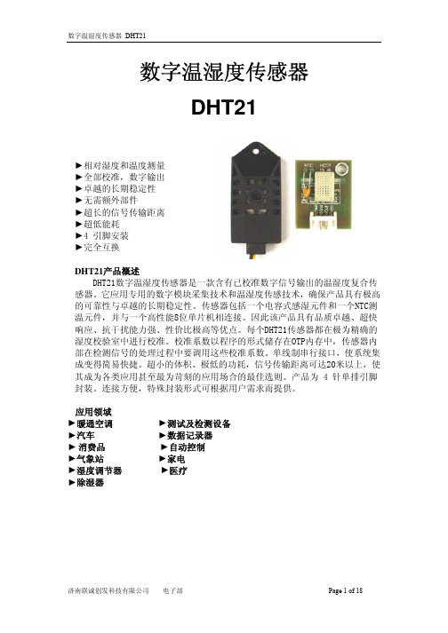
DHT21温湿度模块产品手册说明书

温湿度模块DHT21产品手册一、产品概述本产品是采用高稳定性电容式感湿元件作为传感元件,经过微处理器采集处理转化成数字信号输出。
每一个传感器都经过标定校准和测试。
具有长期稳定、可靠性高、精度高、低功耗等特点。
二、尺寸图单位:mm(±0.5)三、产品特点DHT21数字温湿度模块具有以下特点:1、数字输出,单总线协议,通信距离支持100米;2、超低功耗;3、0-100%相对湿度测量范围;4、全标定、温漂校准。
5、使用独立感湿元器件,稳定性好,抗污染能力强四、性能特征相对湿度温度五、电气特性参数条件最小典型最大单位供电电压VDD 2.83.3 5.5V 供电电流休眠模式0.2uA 测量模式500uA 采样周期 2.0S低电平输出电压Io<4mA 0250mV 高电平输出电压Rp<25kΩ80%100%VDD 低电平输入电压下降沿0%20%VDD 高电平输入电压上升沿80%100%VDD 输出电流On 4mA 三态门(Off)1020μA表3Io 表示低电平输出电流Rp 代表上拉电阻参数条件最小典型最大单位分辨率0.1%RH 量程范围099.9%RH 精度25℃±3%RH重复性±0.1响应时间1/e(63%)<8S迟滞±0.5漂移典型值<3%RH/r 参数条件最小典型最大单位分辨率0.1℃工作范围-4080℃精度±0.5℃重复性±0.2℃响应时间1/e(63%)1S迟滞±0.1漂移典型值<0.2℃/r图1图2表1表2六、用户指南1、引脚分配引脚名称描述1VDD 电源2.8~5.5V 2SDA 串行数据,双向口3NC NC 4GND 地表4:引脚分配1.1、电源引脚(VDD GND)本产品的供电电压为2.8~5.5V,建议供电电压为3.3V。
1.2、串行数据(SDA)SDA 为数据口,三态结构,SDA 在SCK 时钟下降沿之后改变状态,并仅在SCK 上升沿有效2、通信协议DHT21为了精确测量气体的湿度,减少温度对测量的影响,DHT21传感器在非工作期间,自动转为休眠模式,以降低传感器自身的发热对周围气体湿度的影响。
温湿度传感器SHT21的应用介绍

温湿度传感器SHT21的应用介绍近年来,随着智能手机、平板电脑等移动设备的迅速发展,其中内置的微机电系统(MEMS)的比例越来越高。
根据市调机构Juniper Research公布的最新研究报告,预计到2016年应用到移动设备中的MEMS器件收入将超过60亿美金。
其中除了已经大规模应用的加速度计、陀螺仪、重力感应计、麦克风、射频器件等,还包括刚进入商用不久的压力传感器、扬声器、轨迹球、微型投影机、温湿度传感器等。
其中温湿度传感器等新兴的MEMS器件则有望成为智能手机硬件差异化的重要部件。
"目前,我们公司的传感器每年的出货量已经超出了几千万片,全球业务增长幅度近年来都在40%左右。
"总部位于瑞士的深圳盛思锐(Sensirion)公司总经理Paul Chia表示,作为全球领先的传感器制造商,盛思锐公司早在七年前就已经进入中国市场,并向中国厂商推广温湿度传感器。
"我们的产品在中国市场主要分三大应用:第一是安防监控;第二是节能,普遍应用到家电,汽车等领域;第三则是舒适度,主要应用于消费类电子产品领域。
"在2009年,盛思锐公司推出了一款当时世界上最小的数字湿度和温度传感器--SHT21,引起市场广泛关注。
一直以来,盛思锐在推广温湿度传感器的过程中,都非常注重于宣传舒适度概念。
"之前的客户只有温度的概念,而没有湿度概念。
其实相对湿度是与温度密切相关的,只有对同一测量点的湿度和温度进行数据采集,才能保证相对湿度的准确性。
"Paul Chia表示,人体对空气湿度的舒适感应空间较窄,因此需要通过感应器来感知湿度,随时补充或降低水分。
在2009年,盛思锐公司推出了一款当时世界上最小的数字湿度和温度传感器-SHT21,引起市场广泛关注。
盛思锐是业内第一家将温、湿度传感器集成到一起的厂商。
"我们不仅仅是提供一个感应器,而是把温度补偿和标定数据都集成在一个电路里面。
sensirion shtix 数字温湿度传感器 技术手册说明书

技术手册SHT1x (SHT10, SHT11, SHT15)数字温湿度传感器∙ 完全标定 ∙ 数字信号输出 ∙ 低功耗∙ 卓越的长期稳定性∙ SMD 封装 – 适于回流焊接外形尺寸图1 SHT1x 传感器尺寸(1mm=0.039inch),“11”表示该传感器型号为SHT11。
外部接口:1:GND, 2: DATA, 3: SCK, 4: VDD传感器芯片此说明书适用于SHT1x-V4。
SHT1x-V4 是第四代硅传感芯片,除了湿度、温度敏感元件以外,还包括一个放大器,A/D 转换器,OTP 内存和数字接口。
第四代传感器在其顶部印有产品批次号,以字母及数字表示,如“A5Z”,见图1。
材质传感器的核心为CMOS芯片,外围材料顶层采用环氧LCP ,底层为FR4。
传感器符合ROHS 和WEEE 标准,因此不含Pb, Cd, Hg, Cr(6+), PBB, PBDE。
实验包如要进行直接的传感器测量,传感器性能检验或者温湿度实验(数据记录),客户可选用EK-H4,其中包含SHT71(与SHT1x 的芯片相同)传感器,4路传感器通道和与电脑配套的软、硬件。
更多其他传感器实验包信息请登录/humidity产品概述SHT1x (包括 SHT10, SHT11 和 SHT15) 属于Sensirion 温湿度传感器家族中的贴片封装系列。
传感器将传感元件和信号处理电路集成在一块微型电路板上,输出完全标定的数字信号。
传感器采用专利的CMOSens® 技术,确保产品具有极高的可靠性与卓越的长期稳定性。
传感器包括一个 电容性聚合体测湿敏感元件、一个用能隙材料制成的测温元件,并在同一芯片上,与14 位的A/D 转换器以及串行接口电路实现无缝连接。
因此,该产品具有品质卓越、响应迅速、抗干扰能力强、性价比高等优点。
每个传感器芯片都在极为精确的湿度腔室中进行标定,校准系数以程序形式储存在OTP 内存中,用于内部的信号校准。
DHT21规格书
U8checkdata EQU 36H
U8temp
EQU 37H
temp
EQU 38H
济南联诚创发科技有限公司 电子部
Page 6 of 18
数字温湿度传感器 DHT21
;--------------------
;--------------------
;--------------------
org 0000h
图2
济南联诚创发科技有限公司 电子部
Page 3 of 18
数字温湿度传感器 DHT21
高电平后就是数据位,每1bit数据都是由一个低电平时隙和一个高电平组 成。低电平时隙就是一个50us左右的低电平,它代表数据位的起始,其后的高电 平的长度决定数据位所代表的数值,较长的高电平代表1,较短的高电平代表0。 共40bit数据,当最后一Bit数据传送完毕后,从机将再次拉低总线50us左右,随 后释放总线,由上拉电阻拉高。 数字1信号表示方法如图4所示
湿度数据
温度数据
校验和
湿度高8位+湿度低8位+温度高8位+温度低8位=的末8位=校验和
例如:0000 0010+1000 1100+0000 0001+0101 1111=1110 1110
湿度=65.2%RH 温度=35.1℃
当温度低于0℃时温度数据的最高位置1。
例如:-10.1℃表示为1000 0000 0110 0101
DATA信号线材质量会影响通讯距离和通讯质量,推荐使用高质量屏蔽线。
8、封装信息
济南联诚创发科技有限公司 电子部
Page 5 of 18
数字温湿度传感器 DHT21
9、 DHT21引脚说明
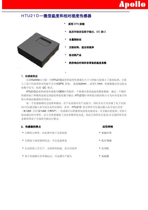
SHT10,SHT11,SHT20,SHT21替代品温湿度传感器HTU21D
最小值
-40
-40 -40
典型值
0.01 0.04
±0.3 ±0.4
44 22 11 6 10
最大值
+125
125 221 58 29 15
8
单位
℃ ℃ ℃
℃ ℃ ℃ °F ms ms ms ms s
9.温度误差估算
温湿度感应芯片HTU21D郑:18070430980
10.焊接说明 可以使用标准的回流焊炉对 HTU21 进行焊接。传感器完全符合 IPC/JEDEC J-STD-020D 焊
2.传感器的特点
·完整的互换性,在标准环境下无需校准 ·长期处于湿度饱和状态,可以迅速恢复 ·自动组装工艺生产,无铅材料制成,适合回流焊 ·每个传感器具有单独标记,可追溯生产源头
应用举例
·家庭应用 ·医疗领域 ·打印机 ·加湿器
3.性能规格
参数
储藏温度
供电电压(峰值)
湿度测量范围
温度测量范围
VDD to GND 数字 I/O 口引脚(DATA/SCK)to VDD 每个引脚输入电流
·相对湿度转换
不论基于哪种分辨率,相对湿度RH 都可以根据SDA 输出的相对湿度信号SRH通过如下 公式计算获得 (结果以 %RH 表示):
例如16位的湿度数据为0x6350:25424,相对湿度的计算结果为42.5%RH。
·温度转换
不论基于哪种分辨率,温度T 都可以通过将温度输出信号ST代入到下面的公式计算得到 (结果以温度°C 表示):
无论哪种传输模式,由于测量的最大分辨率为14 位,第二个字节SDA 上的后两位LSBs (bit43 和44)用来传输相关的状态信息。两个LSBs 中的bit1 表明测量的类型(’0’温度;‘1’: 湿度)。bit0 位当前没有赋值。
温湿度传感器产品说明书
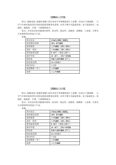
特点:湿敏电阻(湿敏传感器)是在导电半导体陶瓷基片上涂履一层高分子感湿膜,与空气中相对湿度变化导致电阻值系数变化原理。
应用于数字式温湿度表、电子温湿度计、加湿机、抽湿机、空调、气象测量场合。
优点:具有良好的灵敏感应特性、防水性、稳定性、高精度、低飘移,工业级,可替代日本韩国等同类进口产品。
SHR01-313K特点:湿敏电阻(湿敏传感器)是在导电半导体陶瓷基片上涂履一层高分子感湿膜,与空气中相对湿度变化导致电阻值系数变化原理。
应用于数字式温湿度表、电子温湿度计、加湿机、抽湿机、空调、气象测量场合。
优点:具有良好的灵敏感应特性、防水性、稳定性、高精度、低飘移,工业级,可替代日本韩国等同类进口产品。
特点:湿敏电阻(湿敏传感器)是在导电半导体陶瓷基片上涂履一层高分子感湿膜,与空气中相对湿度变化导致电阻值系数变化原理。
应用于数字式温湿度表、电子温湿度计、加湿机、抽湿机、空调、气象测量场合。
优点:具有良好的灵敏感应特性、防水性、稳定性、高精度、低飘移,高性价比,可替代日本神荣、北陆、韩国等同类进口产品。
SHR02-313K特点:湿敏电阻(湿敏传感器)是在导电半导体陶瓷基片上涂履一层高分子感湿膜,与空气中相对湿度变化导致电阻值系数变化原理。
应用于数字式温湿度表、电子温湿度计、加湿机、抽湿机、空调、气象测量场合。
优点:具有良好的灵敏感应特性、防水性、稳定性、高精度、低飘移,高性价比,可替代日本神荣、北陆、韩国进口等同类产品。
特点:湿敏电阻(湿敏传感器)是在导电半导体陶瓷基片上涂履一层高分子感湿膜,与空气中相对湿度变化导致电阻值系数变化原理。
应用于数字式温湿度表、电子温湿度计、加湿机、抽湿机、空调、气象测量场合。
优点:具有良好的灵敏感应特性、防水性、稳定性、高精度、低飘移,高性价比,可替代日本神荣、北陆、韩国进口等同类产品。
特点:电容式温湿度模块是将湿度传感器非线性电阻值转换为线性电压信号输出,体积小,使用方便,精度高。
温湿度传感器说明书
温湿度传感器说明书首部分:引言温湿度传感器是一种用于测量环境中温度和湿度的仪器。
它采用先进的技术和设计,可以提供高精度、快速响应和可靠性的温湿度数据。
本说明书将详细介绍温湿度传感器的工作原理、使用方法和注意事项。
第一部分:工作原理温湿度传感器利用测量元件和电路来获取环境中的温度和湿度数据。
测量元件通常是基于电容、电阻或半导体等原理,并通过准确测量元件的物理变化来计算温度和湿度值。
电路部分则负责放大、滤波和转换信号,以提供数字或模拟输出。
第二部分:使用方法1. 安装温湿度传感器通常需要正确安装才能获得准确的数据。
请将传感器放置在需要测量温湿度的位置,尽量避免遮挡或受到外部干扰。
保持传感器与被测区域的充分接触,并确保传感器与其他设备之间有足够的空间。
2. 连接温湿度传感器通常具有标准的接口和电源要求。
根据传感器的型号和要求,正确连接传感器到检测或控制系统。
注意接线的正确性和稳定性,以免影响数据的准确性和传输质量。
3. 校准为了获得更准确的数据,定期对温湿度传感器进行校准是必要的。
校准可以通过专业的仪器或参照标准数据进行。
校准过程应在环境条件稳定的情况下进行,并确保校准后的传感器能够正常工作。
第三部分:注意事项1. 温度和湿度范围不同型号和品牌的温湿度传感器具有不同的工作范围。
在选择和使用传感器时,请仔细阅读产品说明书,并确保传感器的工作范围符合您的需求。
超出工作范围可能导致数据的不准确或传感器的损坏。
2. 清洁和保养保持温湿度传感器的清洁和正常维护是确保长期准确运行的关键。
定期清理传感器表面和连接器,避免灰尘、污垢或液体进入传感器内部。
避免使用有害的化学物质清洁传感器,以免对其性能造成损害。
3. 环境干扰外部环境的干扰可能影响温湿度传感器的工作精度和稳定性。
避免将传感器放置在极端条件下,如强烈日光照射、高温高湿或强电磁场环境。
同时,避免传感器受到机械冲击或震动。
结尾部分:总结与展望温湿度传感器是现代生活中广泛应用的仪器,它可以在工业、农业、医疗、环境监测等领域发挥重要作用。
湿度与温度传感器数据表说明书

• Measuring range from 5 to95% RH and from 0 to 50 °C(1)or from -20 to 80 °C(2)• 0-10 V output, active, powersupply 24 Vac/Vdc (3-4 wires)or 4-20 mA output, passive loop,power supply from 16 to 30 Vdc(2 wires)• ABS V0 housing IP65(2) or IP20(1),with or without display• Alternating display of humidity andtemperature• “¼ turn” system mounting withwall-mount plate• Housing with simplified mountingsystemFeatures of housingPart numberPower supply / OutputA: Active 24 Vac/Vdc – 0-10 VP: Passive – 16/30 Vac - 4-20 mADisplayO: With displayN: Without displayType of probeS: AmbientA: DuctD: RemoteExample: TH 110 – ANSHumidity and temperature transmitter TH 110,0-10 V active, without display, ambient model.(1) Ambient model / (2) Duct and remote modelDuct model, stainless steel probeProbe cable length (remote models only)( ): cable lentgh 2 m (standard model)05M: cable length 5 m10M: cable length 10 mTechnical specificationsConnectionsInside the front housing 1. Actif switch (S1)2. Inactive switch3. LCC-S software connection4. Output terminal block5. Power supply terminal block6.Cable glandSimplified calibrationElectronic board and measuring element connected to the front side of the sensor, which allows toconfigure and calibrate your device without causing any damage.12Removable front faceFixed back housing6543General features*Can be configured by switch.**All the accuracy indicated in this technical datasheet were stated in laboratory conditions, and can be guaranteed for measurements carried out in the same conditions, or carried out with calibration compensation.Electrical connections NFC15-100This connection must be made by a qualified and trained technician. To make the connection, the transmittermust not be energized.For TH 110-AOS, TH 110-ANS, TH 110-AOD, TH 110-AND,TH 110-AOA, TH 110-ANA models with 0-10 V output – active:For TH 110-POS, TH 110-PNS, TH 110-POD, TH 110-PND, TH 110-POA, TH 110-PNA models with 4-20 mA output – passive:To make a 3-wire connection, before powering up the transmitter, please connect the output ground to theinput ground. See drawing below.IRH VdcIT Vdc IRH VdcIT Vdc VT GND VRH VT GND VRH1 2 3 4 56 7 + - +- +1 2 3 4 5 6 7- +- +or IRH VdcIT Vdc 1 2 3 4 5 6 7- +- +IRH VdcIT Vdc 2 wiresSymbols usedFor your safety and in order to avoid any damage of the device, please follow the procedure described in this document and read carefully the notes preceded by the following symbol:The following symbol will also be used in this document, please read carefully the information notes indicated after this symbol:VT GND VRH+-IRH Vdc IT Vdc IRH Vdc IT VdcF T _E N – T H 110 – 15/01/2021– N o n-c o n t r a c t u a l d o c u m e n t – W e r e s e r v e t h e r i g h t t o m o d i f y t h e c h a r a c t e r i s t i c s o f o u r p r o d u c t s w i t h o u t p r i o r n o t i c e .Only the accessories supplied with the device must be used.T o configure the transmitter , it must not be energized. Then, you can make the settings required, with the DIP switches (as shown on the drawing below). When the transmitter is configured, you can power it up.Please follow carefully the combinations beside with the DIP switch. If the combination is wrongly done, the following message will appear on the display of the transmitter “CONF ERROR”. In that case, you will have to unplug the transmitter , place the DIP switches correctly, and then power the transmitter up.1234Off OnActive switchUnit settingOutput setting On-off switch1234Active switch (S1)Please refer to the user manual of the LCC-S software to make the configuration.Set the DIP switches as shown beside.Connect the cable of the LCC-S to the connection of the transmitter.PC configurationSettings and use of the transmitterIt is possible to set the measuring ranges and the unit of the instrument either by switch and/or via software.ConfigurationAmbient model does not have any mounting plate. 4 fixing holes are present inside the back housing. Use them to install the transmitter on the required location.Configuration via LCC-S software (option)It is possible to configure intermediate ranges, an offset...Example: for a 0-100 °C transmitter, minimum delta minimum is 20 °C. The instrument can be configured from 0 to +20 °C or from -10 to +10 °C. In order to compensate a possible drift of the sensor, it is possible to add an offset to the displayed value by the TH110 transmitter: it shows 48% RH, a standard instrument shows 45% RH. It is then possible, via the software, to integrate an offset of -3 to the displayed value by the TH 110 instrument. The configuration of the parameters can be done either with the DIP switch or via software (you can not combine both solutions).Maintenance:• Avoid any aggressive solvent.• Protect the transmitter and its probes from any cleaning product containing formalin, that may be used for cleaning rooms or ducts.Precautions for use: always use the device in accordancewith its intended use and within parameters described in the technical features in order not to compromise the protection ensured by the device.WarrantyInstruments have 1-year guarantee for any manufacturing defect.。
Sensirion SHTxx 湿度与温度传感器操作指南说明书

Handling InstructionsFor SHTxx Humidity and Temperature SensorsAbstractSensirion SHTxx are relative humidity and temperature sensors of high quality. For taking advantage of their outstanding performance some precautions must be taken during storage, assembly and packaging. Therefore, please read the following instructions carefully - preferably during design-in phase and before production release of the respective device. Special attention is required regarding the exposure to volatile organic compounds, i.e. high concentration and long exposure time to respective gases shall be avoided. Such conditions are known to occur in manufacturing environment and/or during storage. Therefore, proper handling and choice of materials are crucial. Applying sensors in the field in ambient environment is not critical.ApplicabilityThis document is applicable to all Sensirion SHTxx humidity and temperature sensors.ESD protectionThe sensor shall be protected from ESD (Electrostatic Discharge) and only be handled in ESD protected areas (EPA) under protected and controlled conditions (ground all personnel with wrist-straps, ground all non-insulating and conductive objects, exclude insulating materials from the EPA, operate only in grounded conductive floor, etc.). Protect sensor outside the EPA using ESD protective packaging.Protection against ESD is mandatory. Exposure to chemicalsHumidity and Temperature sensors are highly accurate environmental sensors and as such they are not ordinary electronic components. The opening in the package exposes the sensor to the environment and makes it susceptible to pollutants. While applying sensors in the field in ambient environment is not critical, pollutants are known to occur in manufacturing environments and during storage. Please carefully follow the guidelines in this application note to ensure that you can benefit of the sensor’s outstand ing performance.The sensor shall not get in close contact with volatile chemicals such as solvents or other organic compounds. Especially high concentration and long exposure must be avoided. Ketenes, Acetone, Ethanol, Isopropyl Alcohol, Toluene, etc. are known to cause drift of the humidity reading –irreversibly in most of the cases. Please note that such chemicals are integral part of epoxies, glues, adhesives, etc. and outgas during baking and curing. These chemicals are also added as plasticisers into plastics, used for packaging materials, and do out-gas for some period.Acids and bases may affect the sensor irreversibly and shall be avoided: HCl, H2SO4, HNO3, NH3etc. Also Ozone in high concentration or H2O2have the same effect and therefore shall be avoided. Please note, that above examples represent no complete list of harmful substances.The sensor shall not get in contact with cleaning agents (e.g. PCB board wash after soldering) or strong air blasts from an air-pistol (not oil-free air). Applying cleaning agents to the sensor may lead to drift of the reading or complete breakdown of the sensor.Ensure good ventilation (fresh air supply) to avoid high concentrations of volatile chemicals (solvents, e.g. ethanol, isopropanol, methanol, acetone, cleaning solutions, detergents…).Packaging and storagePrior to assembly or use of the sensors it is strongly recommended to store the sensors in the original sealed ESD bag at following conditions: Temperature shall be in the range of 10°C – 50°C (0 – 125°C for limited time) and humidity at 20 – 60%RH (sensors that are not stored in ESD bags).Store sensors in original, unopened ESD bag. Place additional stickers only on the outside of the ESD bag.Once sensors have been removed from the original ESD bag we recommend to store the individual sensors as well as devices with assembled sensors in metal-in antistatic shielded ESD bags. In particular, it is recommended not to use any adhesive or adhesive tapes to reseal the sensor bag after opening. Following ESD Bags can be recommended (no polluting effect on humidity sensor):ESD Bag Manufacturer ProductStroebel"Topshield" BagsSensors as a component or mounted into the final product shall not be packaged in outgassing plastic materials which could cause sensor pollution. Besides metal-in antistatic shielded ESD bags, paper or cardboards based packaging, deep drawn plastic trays (PE, PET, PP) may be considered. Do not use antistatic polyethylene bags (light blue, pink or rose color); be very careful with bubble foils and foams.Be careful about stickers present inside the packing (e.g. on the housing of the device). Sticker size should be kept to a minimum, and the sticky side shall fully adhere onto a surface.Please note that many packaging materials may be provided with additives (plasticizers) which may have a polluting effect on the sensor. Generally speaking, if a material emits a strong odour you should not use it. Additives may also be added to materials which are listed for recommended use. For high safety, device housing and shipment packaging must be qualified. Such a qualification test may contain exposure of the final device with sensor in its shipment packaging to temperature ≥65°C for at least 168 hours. (If shipping or storage conditions are expected to be harsh, the qualification test conditions for the packing material have to be customized.) The sensor reading then shall showno changed deviation against a reference compared to same measurements before the exposure.Do not use polyethylene antistatic bags (light blue, pink or rose color). Do not use adhesive tapes inside packaging.For guidance on simple and straight-forward testing of humidity sensors please consult the Testing Guide for humidity sensors.Assembly - SolderingFor soldering, standard reflow soldering ovens may be used. The sensors are designed to withstand soldering profile according to IPC/JEDEC J-STD-020 with peak temperatures at 260°C during up to 30sec for Pb-free assembly in IR/Convection reflow ovens (see Error! Reference source not found.).Make sure that maximum temperatures and exposure times are respected. In case the PCB passes through multiple solder cycles (as is the case for e.g. PCB that are assembled on top and bottom side), it is recommended to assemble the SHTxx only in the last solder cycle. This is to reduce risks of sensor pollution.Figure 1 Soldering profile according to JEDEC standard. T P ≤ 260°C and t P ≤ 30sec above 255°C for Pb -free assembly. T L < 220°C and t L < 150sec. Ramp-up rate <3°C and ramp-down rate < 6°C/sec for temperatures > T L .SHT31 – 500pcsInspectedT e m p e r a t u r eTimet P T PT L T S (max)t Lpreheatin liquid phaseThe use of “no clean” type ≥3 solder paste 1 is strongly recommended as no board wash can be applied to SHTxx humidity sensors. An appropriate amount of solder paste shall be used, to result in a stand-off height (clearance between the package body and any part of the substrate) of 50μm to 75μm. Please consult the appropriate sensor data sheet for device specific information on the metal land pattern and recommendations on solder paste printing stencils. Standard pick & place equipment and vacuum nozzles for standard QFN packages may be used for assembly of SHTxx and STSxx sensors.Manual soldering is not recommended. For rework soldering, contact time must be limited to 5 seconds at up to 350°C.Immediately after the exposure to high temperatures SHTxx humidity sensors may temporarily read a negative humidity offset (typ. -1 to -2 %RH after reflow soldering). This offset slowly disappears again by itself when the sensor is exposed to ambient conditions (typ. within 1-3 days). If RH testing is performed immediately after reflow soldering, this offset should be considered when defining the test limits.It is important to note that the diced edge or side faces of the I/O pads may oxidise over time, therefore a solder fillet may or may not form. Hence there is no guarantee for solder joint fillet heights of any kind.Assembly – OthersSensors in SMT packages are classified as Moisture Sensitivity Level 1 (IPC/JEDEC J-STD-020). It is recommended to process the sensors within 1 year after date of delivery.Before developing the assembly process, please read the User ’s Guide and the Datasheets carefully. In the following, crucial items are underlined plus additional items are given:No mechanical force shall be applied to any part of the sensor during assembly or usage.No board wash shall be applied to SHTxx humidity sensors. Therefore, and as mentioned in the previous section , it is strongly recommended to use “no -clean” solder paste.1 Solder types are related to the solder particle size in the paste: Type 3covers the size range of 25 – 45 µm as specified in IPC J-STD-005A .Do not apply board wash.For application in corrosive environment – such as condensed water or corrosive gases – it may be necessary to protect the electronic assembly including the soldered contacts of the sensor with a passivation. Such passivation may be achieved by conformal coating or by applying adhesive.Low viscose conformal coatings or potting materials may flow into the inside the sensor cap, cover the sensor element and thus make the humidity sensor inoperative. Use only high viscose conformal coatings or potting materials, or seal the interface between sensor cap and sensor PCB before applying conformal coating. In any case, covering the humidity sensor opening with any kind of coating must be avoided. Therefore, the top surface of the sensor should remain free of coating.If conformal coating is applied, the top surface of the sensor must remain free of coating.Solvent vapors are produced during curing and processing of the coating. Ensure good ventilation throughout the application, staging and curing to prevent pollution of the sensor. Ventilation shall be established in such a way that the concentration of these gaseous substances remains low, e.g. by using ovens with fresh air supply.XXXCoating thickness and curing times shall be chosen according to respective datasheets and application notes of the manufacturer. If a time frame for curing is provided it is recommended to apply the upper time limit. This is especially true if the PCB design features large components with undercuts where high layer thicknesses on/under components or drain-off edges can form. Please note that the tack-free state of the coating is no indication of full curing. For full curing refer to application notes of the manufacturer. Ensure process stability for coating thickness and apply corresponding safety margins for curing times.The following table lists conformal coatings which have been tested regarding pollution of the humidity sensorand are known to be suitable if applied and fully cured under good ventilation and according to respective datasheet.Conformal CoatingsManufacturer ProductPeters Elpeguard SL 1301 ECO-FLZ Electrolube AFA (Aromatic Free Acrylic) Coating Chase HumiSeal 1B51NSLUDow Corning Dow corning 1-2620Do not apply spray to unprotected sensor. Whenever using spray coating techniques (e.g. to apply varnish or conformal coating, etc.) the SHT3x with protective cover option can be used or the SHTxx sensor has to be covered by the adhesive tape to prevent coating of the humidity sensor opening. The following table lists adhesive tapes which have been tested regarding pollution of the humidity sensor and are known to be suitable.Adhesive TapesManufacturer Product3M Electrical Tape 92Do not apply any other adhesive tapes such as Scotch Tape, Sello Tape, Tesa Film, etc. In conjunction with the sensor, use only recommended Kapton® tape Electrical Tape 92 by 3M™.Regarding adhesives and encapsulants the material in the following tables may be used –according to respective datasheets, applied and fully cured in well ventilated environment (fresh air supply). Materials and brands not listed in the following tables may be harmful and shall be tested carefully before applying.Epoxy AdhesivesManufacturer ProductEPO-TEK H70E/SEPO-TEK T6067EPO-TEK 93-86Lord MD-130Eccobond E3503-1Ablebond 84-3Epoxy Glob Top EncapsulantsManufacturer ProductStycast 50300 / 50400 seriesHysol EO1061/EO1062Silicone AdhesivesManufacturer ProductRTV 6424 (Momentive)Dow Corning 732Silicone Glob Top EncapsulantsManufacturer ProductStycast S 7503Instant AdhesivesManufacturer ProductLoctite 401PUR (Polyutherane) Casting Compounds Manufacturer ProductPeters VU 4457-61Hot melts may absorb water and thus may have an impact on the response time of the sensor in the device. Therefore, hot melt shall be applied sparingly.The sensor shall be mounted into the device, if possible, after all materials that are used in the assembly process have completely cured or dried out. Otherwise ensure good ventilation (fresh air supply) in curing ovens and assembly lines.Prevent any dust or particles from entering the sensor opening (sensor performance may be affected).Wear clean gloves or finger cots while handling the sensor and avoid touching the sensor opening.Ensure recommendations in this application note are equally considered during repair and rework of assemblies containing sensors. During repair and rework, it may be recommendable to cover the sensor with Kapton tape (specific recommendation see above). Be particularly careful when using strong cleaning agents (e.g. detergents, alcohols, brominated or fluorinated solvents). Cleaning any part of a product might lead to high concentration of cleaning agents on the sensor. Please remove any sensors or devices containing sensors before cleaning the production area and tools. Ensure good ventilation (fresh air supply) and that any solvents have evaporated before resuming production.Prevent sensor from exposure to cleaning agents. Application in extreme environment Some applications require the exposure of humidity and temperature sensors to harsh environments. In many of the cases the sensor is uncritical to be used. However, some precautions must be taken.For exposure to extreme conditions with regards to humidity and temperature please consult the datasheet 275%RH can conveniently be generated with saturated NaCl solution. of respective product. Please make sure that exposure time of the sensor to maximum range of operating conditions is limited as given in datasheet. Exposure to volatile organic compounds at high concentration and long exposure time is critical not only in assembly but also in the field. Such application needs to be carefully tested and qualified.Exposure to acids or bases may be critical, too. In order to be critical, the concentration must be such that polymers are attacked. For bases there is a rule of thumb that pH<9 are uncritical. Etching substances such as H2O2, NH3, etc. at high concentrations are critical to the sensor, too.Corrosive substances at very low concentrations are not critical to the sensor itself. However, they may attack the solder contacts. Therefore, the contacts must be well protected (passivated) in case of an application to such environment –compare also Section “Assembly”. Application of Sensirion humidity and temperature sensors to harsh environment must be carefully tested and qualified. Sensirion qualifies its humidity and temperature sensors to work properly within ambient clean air – qualification for use in harsh environment is duty of the user of the sensor. Reconditioning procedureAs stated above extreme conditions or exposure to solvent vapors may offset the sensor. The following reconditioning procedure may bring the sensor back to calibration state:Baking: 100 – 105°C at < 5%RH for 10hRe-Hydration: 20 – 30°C at ~ 75%RH for 12h 2. DisclaimerThe above given restrictions, recommendations, materials, etc. do not cover all possible cases and items. The material recommendations are given with regard to pollution of SHTxx sensors and assume optimal processing for avoiding VOC in process – the materials were not tested regarding other properties like reliability, performance, usability or mechanical properties. The material recommendations have been compiled with our best knowledge at the time of writing. Manufacturers may change the compounds without notice, which can lead to reduced Sensor performance due to outgassing.This document is not to be considered complete and is subject to change without prior notice.Revision historyImportant NoticesWarning, Personal InjuryDo not use this product as safety or emergency stop devices or in any other application where failure of the product could result in personal injury. Do not use this product for applications other than its intended and authorized use. Before installing, handling, using or servicing this product, please consult the data sheet and application notes. Failure to comply with these instructions could result in death or serious injury.If the Buyer shall purchase or use SENSIRION products for any unintended or unauthorized application, Buyer shall defend, indemnify and hold harmless SENSIRION and its officers, employees, subsidiaries, affiliates and distributors against all claims, costs, damages and expenses, and reasonable attorney fees arising out of, directly or indirectly, any claim of personal injury or death associated with such unintended or unauthorized use, even if SENSIRION shall be allegedly negligent with respect to the design or the manufacture of the product.ESD PrecautionsThe inherent design of this component causes it to be sensitive to electrostatic discharge (ESD). To prevent ESD-induced damage and/or degradation, take customary and statutory ESD precautions when handling this product.See application note “ESD, Latchup and EMC” for more information.WarrantySENSIRION warrants solely to the original purchaser of this product for a period of 12 months (one year) from the date of delivery that this product s hall be of the quality, material and workmanship defined in SENSIRION’s published specifications of the product. Within such period, if proven to be defective, SENSIRION shall repair and/or replace this product, in SENSIRION’s discretion, free of charge to the Buyer, provided that:•notice in writing describing the defects shall be given to SENSIRION within fourteen (14) days after their appearance;•such defects shall be found, to SENSIRION’s reasonable satisfaction, to have arisen from SENSIRION’s faulty design, material, or workmanship;•the defective product shall be returned to SENSIRION’s factory at the Buyer’s expense; and•the warranty period for any repaired or replaced product shall be limited to the unexpired portion of the original period.This warranty does not apply to any equipment which has not been installed and used within the specifications recommended by SENSIRION for the intended and proper use of the equipment. EXCEPT FOR THE WARRANTIES EXPRESSLY SET FORTH HEREIN, SENSIRION MAKES NO WARRANTIES, EITHER EXPRESS OR IMPLIED, WITH RESPECT TO THE PRODUCT. ANY AND ALL WARRANTIES, INCLUDING WITHOUT LIMITATION, WARRANTIES OF MERCHANTABILITY OR FITNESS FOR A PARTICULAR PURPOSE, ARE EXPRESSLY EXCLUDED AND DECLINED.SENSIRION is only liable for defects of this product arising under the conditions of operation provided for in the data sheet and proper use of the goods. SENSIRION explicitly disclaims all warranties, express or implied, for any period during which the goods are operated or stored not in accordance with the technical specifications.SENSIRION does not assume any liability arising out of any application or use of any product or circuit and specifically disclaims any and all liability, including without limitation consequential or incidental damages. All operating parameters, including without limitation recommended parameters, must be validated for each customer’s applications by customer’s technical experts. Recommended parameters can and do vary in different applications.SENSIRION reserves the right, without further notice, (i) to change the product specifications and/or the information in this document and (ii) to improve reliability, functions and design of this product.Copyright© 2021, by SENSIRION. CMOSens® is a trademark of Sensirion. All rights reservedHeadquarters and SubsidiariesSensirion AG Laubisruetistr. 50CH-8712 Staefa ZH Switzerlandphone: +41 44 306 40 00 fax: +41 44 306 40 30 ****************** Sensirion Inc., USAphone: +1 312 690 5858*********************Sensirion Korea Co. Ltd.phone: +82 31 337 7700~3*********************/krSensirion Japan Co. Ltd.phone: +81 3 3444 4940*********************/jpSensirion China Co. Ltd.phone: +86 755 8252 1501*********************/cnSensirion Taiwan Co. Ltdphone: +886 3 5506701******************To find your local representative, please visit /distributors。
温湿度控制器说明书

030温湿度控制器安装使用说明书V2.0申明版权所有,未经本公司之书面许可,此手册中任何段落,章节内容均不得被摘抄、拷贝或以任何形式复制、传播,否则一切后果由违者自负。
本公司保留一切法律权利。
本公司保留对手册所描述之产品规格进行修改的权利,恕不另行通知。
订货前,请垂询当地代理商以获悉本产品的最新规格。
江苏安科瑞电器制造有限公司吴磊磊提供135********目录前言 (1)1概述 (1)2工作原理 (1)一WH系列普通型温湿度控制器 (1)1型号说明 (1)2技术指标 (2)3产品规格及功能 (2)4接线方式 (4)二WHD系列智能型温湿度控制器 (5)1型号说明 (5)2技术指标 (5)3产品规格及功能 (6)4接线方式 (6)5产品操作指南 (8)6通讯指南 (11)三传感器 (15)1概述 (15)2型号说明 (15)前言:温湿度控制器简介1概述温湿度控制器产品主要用于中高压开关柜、端子箱、环网柜、箱变等设备内部温度和湿度的调节控制。
可有效防止因低温、高温造成的设备故障以及受潮或结露引起的爬电、闪络事故的发生。
产品分为WH普通型系列和WHD智能型系列。
产品符合国标GB/T15309-1994。
2工作原理温湿度控制器主要由传感器、控制器、加热器(或风扇等)三部分组成,其工作原理如下图所示:传感器检测箱内温湿度信息,并传递到控制器由控制器分析处理:当箱内的温度、湿度达到或超过预先设定的值时,控制器中的继电器触点闭合,加热器(或风扇)接通电源开始工作,对箱内进行加热或鼓风等;一段时间后,箱内温度或湿度远离设定值,控制器中的继电器触点断开,加热或鼓风停止。
除基本功能外不同型号还带有断线报警输出、变送输出、通信、强制加热鼓风等辅助功能。
一.WH系列普通型温湿度控制器1型号说明注:1.“组合外接”即同时有温度、湿度控制时,传感器置于同一外壳,由同一点采集温度、湿度信息。
2.传感器与控制器之间的连接线长度建议不要超过20米。
SHT21_V2.0技术手册
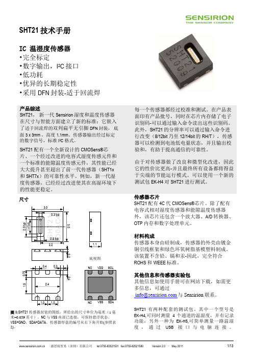
3
如果传感器周围有挥发性溶剂、带刺激性气味的胶带、粘合剂以 及包装材料,读数可能会偏高。详细说明请参阅相关文件。 6 供电电流和功耗的最小值和最大值都是基于 VDD = 3.0V 和 T<60°C. 的条件。平均值为 每秒中进行一次 8bit 测量的数值。 7 响应时间取决于传感器基片的导热率。
盛思锐贸易(深圳)有限公司
tel:0755-82521501 fax:0755-82521580
Version 2.0 – May 2011
2/13
SHT2x 用户指南
1 扩充性能 关于 Sensirion 如何指定和测试传感器的精度 性能,请查阅 Sensirion 应用手册”statement on sensor specification”
每一个传感器都经过校准和测试。在产品表 面印有产品批号,同时在芯片内存储了电子 识别码-可以通过输入命令读出这些识别码。 此外,SHT21 的分辨率可以通过输入命令进 行改变(8/12bit 乃至 12/14bit 的 RH/T),传感 器可以检测到电池低电量状态,并且输出校 验和,有助于提高通信的可靠性。 由于对传感器做了改良和微型化改进,因此 它的性价比更高-并且最终所有设备都将得益 于尖端的节能运行模式。可以使用一个新的 测试包 EK-H4 对 SHT21 进行测试。 传感器芯片 SHT21 配有 4C 代 CMOSens®芯片。除了配有 电容式相对湿度传感器和能隙温度传感器 外,该芯片还包含一个放大器、A/D 转换器、 OTP 内存和数字处理单元。 材料构成 传感器本身由硅制成,传感器的外壳由镀金 铜引线框架和绿色环氧树脂基模塑料制成。 该装置不含铅、镉和汞-因此,完全符合 ROHS 和 WEEE 标准。
-40
温湿度传感器SHT21在安全储粮监测系统中的应用
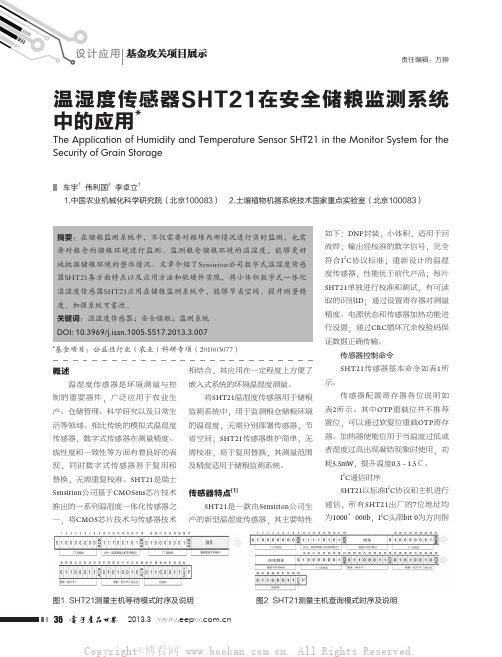
相结合,其应用在一定程度上方便了 嵌入式系统的环境温湿度测量。
将SHT21温湿度传感器用于储粮 监测系统中,用于监测粮仓储粮环境 的温湿度,无需分别部署传感器,节 省空间;SHT21传感器维护简单,无 需校准,易于复用替换,其测量范围 及精度适用于储粮监测系统。
传感器特点[1] SHT21是一款由Sensirion公司生
示位,1为读,0为写。SHT21传感器 有两种测量模式,分别为主机等待模 式(hold master mode)和主机查询模式 (no hold master mode),不同模式可以 应用在不同场合下。测量精度越高, 测量完成所需要的时间越长,根据手 册数据,最长测量时间达88ms。
SHT21传感器针对测量所得数据 运算出对应的循环冗余校验码,并在 传送数据后默认传送。其循环冗余校 验码可以检查出传送过程中奇数错 误、双位错误,以及8位窗口内的任 意长度的串错误。对应的运算多项式
湿度测量命令),在起始 标志以及读地址头部后,释放总线, 等待传感器传送数据以及校验和。主 机需要完成接收每个字节数据后发送 ACK应答,完成全部3个字节接收后 发送NACK应答后再发送结束标志P以 释放I2C总线。
(2)主机查询模式(no hold master mode)
主机查询模式下SDA数据线时序 如图2所示,其中白色部分为主机发 送数据,灰色部分为SHT21发送。与 等待模式不同,主机在发送测量命令
8位窗口应初始化为 00000000’b。如果主机 在接收数据结束后发送 NACK应答,则传感器 不会发送校验和数据。
(1)主机等待模式 (hold master mode)
主机等待模式下 SDA数据线时序如图1所 示,其中白色部分为主 机发送数据,灰色部分 为SHT21发送。在起始 标志S之后依次传送写地 址头部,主机等待模式 测量命令(根据表,此为
DHT21说明书(新版)
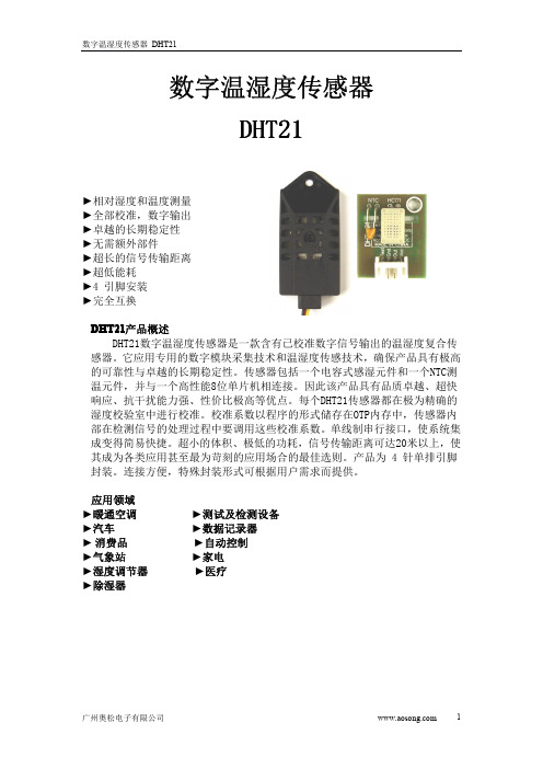
湿度数据
温度数据
校验和
湿度高8位+湿度低8位+温度高8位+温度低8位=的末8位=校验和
例如:0000 0010+1000 1100+0000 0001+0101 1111=1110 1110
湿度=65.2%RH 温度=35.1℃
当温度低于0℃时温度数据的最高位置1。
例如:-10.1℃表示为1000 0000 0110 0101
3、 接口说明
建议连接线长度短于20米时用5K上拉电阻,大于20米时根据实际情况使
用合适的上拉电阻
广州奥松电子有限公司
2
数字温湿度传感器 DHT21
3、 电源引脚 DHT21的供电电压为5V。传感器上电后,要等待 1s 以越过不稳定状态在此期间无
需发送任何指令。电源引脚(VDD,GND)之间可增加一个100nF 的电容,用以去耦滤波。 4、单总线接口
图2 高电平后就是数据位,每1bit数据都是由一个低电平时隙和一个高电平组
广州奥松电子有限公司
3
数字温湿度传感器 DHT21
成。低电平时隙就是一个50us左右的低电平,它代表数据位的起始,其后的高电 平的长度决定数据位所代表的数值,较长的高电平代表1,较短的高电平代表0。 共40bit数据,当最后一Bit数据传送完毕后,从机将再次拉低总线50us左右,随 后释放总线,由上拉电阻拉高。 数字1信号表示方法如图4所示
DATA 用于微处理器与 DHT21之间的通讯和同步,采用单总线数据格式,一次 通讯时间5ms左右 ,具体格式在下面说明,当前数据传输为40bit,高位先出。
数据格式: 40bit数据=16bit湿度数据+16bit温度数据+8bit校验和
温湿度传感器使用说明书
NO:S1*******使用说明书温湿度传感器目录1、产品介绍 (1)1.1概述 (1)1.2功能特点 (1)1.3外观尺寸 (1)2、性能参数 (2)3、使用方法 (4)3.1系统框架图 (4)3.2安装说明 (6)4、通信协议 (9)4.1通讯基本参数 (9)4.2数据帧格式定义 (9)4.3通讯基本参数 (11)4.4通讯协议示例以及解释 (12)5、常见问题及解决方法 (14)6、保养维护 (15)7、运输存储 (16)7.1运输要求 (16)7.2存储要求 (16)8、订货服务 (17)8.1订货方法 (17)8.2客户服务 (17)1产品介绍1.1概述本(系列)产品可在线监测环境温度和湿度信息,广泛用于开关柜仪表室、断路器室、电缆室等处的环境温湿度在线监测。
采用进口工业级微处理器芯片、进口高精度温度传感器,确保产品高精度和可靠性。
1.2功能特点◆进口的测量单元,测量精准。
◆专用的485电路,通信稳定。
◆宽电压范围供电,安装方便。
1.3外观尺寸(单位:mm公差:±0.5)2性能参数3使用方法3.1系统框架图本产品也可以多个传感器组合在一条485总线使用,理论上一条总线可以接254个485传感器,另一端接入带有485接口的PLC 、通过485接口芯片连接单片机,或者使用USB转485即可与电脑连接,使用我公司提供的传感器配置工具进行配置和测试(在使用该配置软件时只能接一台设备)。
3.2安装说明3.2.1注意事项1、传感器应尽量垂直放置,保证安装墙面时,温湿度探头在传感器本体的下方(传感器本体上的字体为正方向)。
2、安装高度为人体坐高或主要测量的环境区域。
3、避免在易于传热且会直接造成与待测区域产生温差的地带安装,否则会造成温湿度测量不准确。
4、安装在环境稳定的区域,避免直接光照,远离窗口及空调、暖气等设备,避免直对窗口、房门。
5、尽量远离大功率干扰设备,以免造成测量不准确,如变频器/电机等。
AHT21 温湿度传感器 产品手册说明书

AHT21 产品手册温湿度传感器• 完全标定应用范围暖通空调 、除湿器、测试及检测设备、消费品、汽车 、自动控制、数据记录器、气象站、家电、湿度调节、医疗及其他相关温湿度检测控制。
图 1: AHT21 传感器封装图(单位:mm 公差:±0.1mm )2• 数字输出,I C 接口• 优异的长期稳定性• 采用SMD封装适于回流焊• 响应迅速、抗干扰能力强Top viewFront viewButtom view0.40.553.03.01.02.0Top viewButtom view1.00.50.50.95传感器性能相对湿度温度图 3温度典型误差和最大误差。
±0±2±4±6±8±10图 2 25°C 时相对湿度的最大误差。
△R H (%RH )相对湿度(%RH )电气特性表2 电气特性。
包装信息此精度为出厂检验时,传感器在 25℃供电电压为3.3V 条件下的测试精度。
此数值不包括迟滞和非线性,并只适用于非冷凝条件。
25℃和1m/s 气流条件下,达到一阶响应 63%所需时间。
正常工作范围:0-80%RH, 超出此范围,传感器读数会有偏差(在90%RH 湿度下 200 小时后,漂移<3%RH)。
如果传感器周围有挥发性溶剂、带刺激性气味的胶带、粘合剂以及包装材料,读数可能会偏高。
详细说明请参阅相关文件。
供电电流和功耗的最小值和最大值都是基于 VDD = 3.3V 和 T<60℃的条件。
平均值为每两秒中进行一次测量的数值。
响应时间取决于传感器基片的导热率。
表 1 湿度特性表表 3 温度特性表表4 包装信息。
123456温度(℃)表1中给出的功耗与温度和供电电压VDD有关。
关于功耗的估测参见图6和7。
请注意图6和7中的曲线为典型自然特性,有可能存在偏差。
图6VDD=3.3V时,典型的供电电流与温度的关系曲线(休眠模式)。
二氧化碳温湿度传感器 室内型 操作手册说明书
操作手册二氧化碳温湿度传感器室内型目录安全注意事项接线图尺寸图软件规划操作流程保养及异常处理安全注意事项●使用本产品之前,用户必须阅读本用户手册的详细信息,然后按照正确的步骤使用本产品。
●使用设置本产品时,本用户手册仅供参考,并且需要妥善保存。
●操作使用上的限制,敬请注意!本产品不适用于防爆区域,请勿在有碍人身安全的情况下使用本产品。
●用于无尘室、动物饲养室等,有可靠性,控制精度等方面的特别要求时,请向本公司的销售人员咨询。
●如果用户将本产品安装在无尘室,动物繁殖环境等特殊环境中,请向本公司的专业销售人员进行专门的产品咨询。
●如果因操作人员不当或环境不正确而导致不正确和危险的后果,本公司将不承担任何法律责任。
警告!●安装前请确认产品是否因运送过程导致外观损坏,或因附件遗失影响产品功能。
●请将本产品安装在本说明书中明确规定的使用环境中使用,否则因此发生故障。
●请在切断供应电源的状态下进行接线作业,否则可能触电及造成设备故障。
●为防止产品损坏,在进行任何接线和安装之前,请务必断开产品的电源。
●请在本说明书规定的额定电源及各工作范围内使用本产品,否则可能引起火灾或设备故障。
●本产品必须在手册规定的操作条件下操作,以防止设备损坏。
●为安全起见,必须由电气安装专业人员配备仪表进行安装和接线,根据所适用的安全标准规范,所有接线必须遵守当地的室内布线规范和电气安装规则。
●关于接线,请按照内部接线规程,电气设备技术标准进行施工,所有接线必须符合室内接线规则和电气安装规则,并需将上盖螺丝及出线端迫紧,才能达到产品等级。
●为防止变频器等的干扰,避免错误信号导致产品损坏,请使用绝缘导线。
●电线的末端请使用有绝缘覆盖的压接端子,及依照接线图方式施工,避免引起短路。
●为避免人身伤害,请勿触摸正在使用的产品的运动部件。
●产品故障时,可能因无输出导致高湿环境状态,或可能使输出高过,请在控制器侧采取安全措施。
●丢弃本产品时,用户必须遵守不同国家地区有关工业生活垃圾的相关规定。
温湿度控制仪表说明书

温湿度控制仪使用说明书温湿度控制仪,具有温湿度同时数字显示,控制值分别显示、定时打印记录等功能,仪表同时具有电压监测功能,缺水保护功能(内部有水位传感器输入接口,只要配接水位传感器,就可以适用需要缺水指示或报警的场合),内置循环定时器,使控制更加灵活,设备配上该仪表,将使其具有很高的自动控制功能。
一、主要技术指标1.1控温范围:0℃----50℃1.2控温灵敏度:±0.5℃控湿灵敏度:±2%RH1.3测温准确度:±0.3℃测湿准确度:5% ~ 7%RH1.4温、湿度控制值及上、下限:可以由用户根据需要设定。
1.5打印记录定时范围:0---999秒可设定。
1.6循环定时器定时范围:工作时间0---9.9分钟、停止时间0---9.9分钟。
1.7上位机通信定时范围:0---9.9分钟。
1.8上限工作延时设定范围:0---9.9分钟。
1.9控温输出功率:电压220V±10%AC、电流5A;控湿输出功率:电流3A;风机输出功率:电流1A。
1.10仪表工作环境条件:0℃---±45℃,相对湿度不大于85%。
1.11仪表工作电压:220V±10%;仪表功耗:<6瓦。
1.12温、湿度传感器:(智能型)1.13仪表安装开空尺寸:1 50×75(mm)。
1.14仪表外形尺寸:160×80×170(mm)。
1.15仪表重量:<1kg1.16打印机:(可扩展)二、工作原理本仪表将干、湿温传感器的等效信号转成相应的数字信号,再由微处理器进行处理后显示和智能控制。
(用户如需定时打印温度和湿度,仪表可扩展时钟和打印机接口。
扩展后,仪表能根据设定的打印时间,定时打印“年、月、日、时、分”和当时的温度、湿度。
使用时应把仪表后面板标有打印机接口(R、T)字样的两个接线端与打印机后面板对应的接线端相连,并把220V交流电源接到打印机后面板标有相,中的接线端。
温湿度传感器使用说明书
温湿度传感器使用说明书●产品概述该温湿度大气压传感器可广泛适用于环境检测,集温湿度、大气压力于一体,安装在百叶盒内,设备采用标准MODBUS-RTU通信协议,RS485信号输出。
该变送器广泛适用于需要测量环境温湿度等场合。
●产品特点●10-30V宽直流电压供电●标准MODBUS-RTU通信协议●宽范围气压量程,可应用于各种海拔高度●技术指标供电电压10~30VDC温度±0.5℃(25℃)精度相对湿度±3%RH(5%RH~95%RH,25℃)温度-40℃~80℃测量范围相对湿度0%RH~100%RH温度0.1℃显示分辨率相对湿度0.1%RH温度0.1℃/y长期稳定性相对湿度0.1%RH/y输出信号(0-5)V、(0-10)V、(4-20)mA、RS485(Modbus RTU通讯协议)工作温度-20~60℃储存温度-40~100℃●产品电气接口及连线方法数字RS485输出接线方式线色引线定义电源红色电源正(10~30V DC)黑色电源负通信绿色RS485-A 白色RS485-B模拟输出接线方式线色引线定义电源红色电源正(10~30V DC)黑色电源负通信绿色温度信号输出正白色温度信号输出负蓝色湿度信号输出正黄色湿度信号输出负注:接线方式以产品引线上说明为准●注意事项1打开产品包装后,请检查产品外观是否完好,核定产品使用说明书相关内容与产品是否一致,并妥善保管产品使用说明书一年以上;2严格按产品接线示意图接线,并在产品允许激励电压下工作,切勿过电压使用;3产品切莫敲打,以免损环外观和内部结构;4产品无客户自行维修部件,出现故障时请与我公司联系;5本公司产品正常情况下使用出现故障,保修期为一年(自我公司发货之日起至返回之日止13个月),是否属于正常情况下出现故障,以我公司质检员检测为依据。
超过期限维修,本公司收取成本费,本公司所有产品终身维修;6未尽之处,请查阅我公司网站或来电查询。
- 1、下载文档前请自行甄别文档内容的完整性,平台不提供额外的编辑、内容补充、找答案等附加服务。
- 2、"仅部分预览"的文档,不可在线预览部分如存在完整性等问题,可反馈申请退款(可完整预览的文档不适用该条件!)。
- 3、如文档侵犯您的权益,请联系客服反馈,我们会尽快为您处理(人工客服工作时间:9:00-18:30)。
5
25°C 和 1 m/s 气流条件下,达到一阶响应 63%所需时间。 4 正常工作范围: 0-80%RH, 超出此范围,传感器读数会有偏差 ( 在 90%RH 湿度下 200 小时后,漂移<3%RH). 工作范围进一步限定在 -40 – 80°C.。更多信息请参考用户指南 1.1.
±5
±7
图 7 在温度为 25°C 时,典型的供电电流与供电电压的关系 曲线(休眠模式)。请注意,这些数据与显示值偏差可能会 达到显示值的±50%。在 60°C 时,系数大约为 15(与表 1 相 比)。
0 5 10 15 20 25 30 35 40 45 50 55 60 65 70 75 80
每一个传感器都经过校准和测试。在产品表 面印有产品批号,同时在芯片内存储了电子 识别码-可以通过输入命令读出这些识别码。 此外,SHT21 的分辨率可以通过输入命令进 行改变(8/12bit 乃至 12/14bit 的 RH/T),传感 器可以检测到电池低电量状态,并且输出校 验和,有助于提高通信的可靠性。 由于对传感器做了改良和微型化改进,因此 它的性价比更高-并且最终所有设备都将得益 于尖端的节能运行模式。可以使用一个新的 测试包 EK-H4 对 SHT21 进行测试。 传感器芯片 SHT21 配有 4C 代 CMOSens®芯片。除了配有 电容式相对湿度传感器和能隙温度传感器 外,该芯片还包含一个放大器、A/D 转换器、 OTP 内存和数字处理单元。 材料构成 传感器本身由硅制成,传感器的外壳由镀金 铜引线框架和绿色环氧树脂基模塑料制成。 该装置不含铅、镉和汞-因此,完全符合 ROHS 和 WEEE 标准。
Relative Humidity (%)
表 1 中给出的功耗与温度和供电电压 VDD 有 关。关于功耗的估测参见图 6 和 7。请注意 图 6 和 7 中的曲线为典型自然特性,有可能 存在偏差。
8 6 4 2 0
100 80 60 40 20 0 -40 -20 0 20 40 60 80 100 120 Temperature (癈)
2
2.1
应用信息
Temperature
TP TL TS (max) tL
tP
焊接说明
DFN的裸焊盘(中间焊盘)和周围的I/O焊盘 由铜引线框架平面基板制成,除这些焊盘暴 露于外面,用于机械和电路连接之外,其余 部分全部包膜成型。使用时,I/O焊盘与裸焊 盘都需要焊接在PCB上。为防止氧化和优化 焊接,传感器底部的焊点镀有Ni/Pd/Au。 在 PCB上, I/O接触面8长度应比SHT21的I/O封 装焊盘大0.2mm,靠内侧的部分要与I/O焊盘的 形状匹配,引脚宽度与DFN封装焊盘宽度比 为1:1,裸露焊盘尺寸与DFN封装比例为1:1,见 图8。 对于网板和阻焊层设计9,建议采用阻焊层开 口大于金属焊盘的铜箔定义焊盘(NSMD)。 对于NSMD焊盘,如果铜箔焊盘和阻焊层之间 的空隙为60µm-75µm,阻焊层开口尺寸应该大于
3
如果传感器周围有挥发性溶剂、带刺激性气味的胶带、粘合剂以 及包装材料,读数可能会偏高。详细说明请参阅相关文件。 6 供电电流和功耗的最小值和最大值都是基于 VDD = 3.0V 和 T<60°C. 的条件。平均值为 每秒中进行一次 8bit 测量的数值。 7 响应时间取决于传感器基片的导热率。
Temperature (°C)
图 5 0 – 80°C 范围内对应的湿度最大误差,单位%RH。
盛思锐贸易(深圳)有限公司
tel:0755-82521501 fax:0755-82521580
Version 2.0 – May 2011
3/13
Datasheet SHT21
1.2
不同温度下的 RH 精度
图 2 中定义了 25°C 时的 RH 精度, 图 5 中 显示了其他温度段的湿度最大误差。
100 90 80 70 60 50 40 30 20 10 0
Relative Humidity (%RH)
±6
±5
±5 ±4
±5
±7
±8
±4
±3
±3
±3
±4
±6
±6
±5
±4 ±5
SHT21 D0AC4
0.8 typ
2.0 typ 1.4 typ
3.0 1.1 0.2
2.2
底视图
NC VDD SCL
0.4 0.75
0.3 0.4
1.5
2.4
其他信息和传感器实验包 其他信息如使用手册可在网站下载,如需更 多信息,可通过 info@ 与 Sensirion 联系。
SHT21 技术手册
IC 温湿度传感器 •完全标定 •数字输出,I2C 接口 •低功耗 •优异的长期稳定性 •采用 DFN 封装-适于回流焊
产品综述 SHT21, 新一代 Sensirion 湿度和温度传感器 在尺寸与智能方面建立了新的标准:它嵌入 了适于回流焊的双列扁平无引脚 DFN 封装, 底
面 3 x 3mm ,高度 1.1mm。传感器输出经过标定 的数字信号,标准 I2C 格式。
焊盘尺寸120µm-150µm。封装焊盘的圆形部分要 匹配相应的圆形的阻焊层开口,以保证有足够的 阻焊层区域(尤其在拐角处)防止焊锡交汇。每 一个焊盘都要有自己的阻焊层开口,在相邻的焊 盘周围形成阻焊层网络。
0.4 0.3 0.4 0.2
preheating
critical zone
Time
图 9 JEDEC 标准的焊接过程图,Tp<=260℃,tp<30sec,无铅焊 接。TL<220℃,tl<150sec,焊接时温度上升和下降的速度应 <5℃/sec。
盛思锐贸易(深圳)有限公司
tel:0755-82521501 fax:0755-82521580
Version 2.0 – May 2011
2/13
SHT2x 用户指南
1 扩充性能 关于 Sensirion 如何指定和测试传感器的精度 性能,请查阅 Sensirion 应用手册”statement on sensor specification”
功耗 6 加热器 通讯
测量状态 平均 8bit VDD = 3.0 V
5.5 mW, T = + 0.5-1.5 °C
两线数字接口, 标准 I2C 协议
表 1 电气特性。关于最大绝对值参看段落 4.1 用户指南 。
本手册可能随时更改,恕不另行通知。
1
默认测量分辨率 14bit (温度.) / 12bit (湿度)。可通过向寄存器发送命 令将其减少到 12/8bit, 11/11bit 或 13/10bit。 2 此精度为出厂检验时,传感器在 25°C (77°F)供电电压为 3.0V 条
2.2 存储条件和操作说明
正常 范围
最大 范围
0
20
40
60
80
100
120
Temperature (°C)
图 6 VDD = 3.0V 时,典型的供电电流与温度的关系曲线(休 眠模式)。请注意,这些数据与显示值存在大约 ±25% 偏 差。
Supply Current IDD (nA)
图 4 工作条件
20 18 16 14 12 10 8 6 2.1 2.3 2.5 2.7 2.9 3.1 3.3 3.5 Supply Voltage (VDD)
-40
-20
0
20
40
60
80
100
120
Temperature (°C)
图 2 25°C 时相对湿度的最大误差,更多信息请参考用户指 南 1.2
图 3 温度典型误差和最大误差。
电气特性
参数 供电电压, VDD 供电电流, IDD 6
休眠模式 测量状态 休眠模式
包装信息
条件 最小 典型 最大 单位 2.1 200 0.6 3.0 0.15 300 0.5 0.9 3.2 3.6 0.4 330 1.2 1.0 V µA µA µW mW µW SHT21 传感器型号 包装 卷带式包装 卷带式包装 卷带式包装 数量 400 1500 5000 订货号 1-100711-01 1-100700-01 1-100699-01
SHT21 配有一个全新设计的 CMOSens®芯 片、一个经过改进的电容式湿度传感元件和 一个标准的能隙温度传感元件,其性能已经 大大提升甚至超出了前一代传感器(SHT1x 和 SHT7x)的可靠性水平。例如,新一代湿 度传感器,已经经过改进使其在高湿环境下 的性能更稳定。
尺寸
3.0 0.3 typ
4
最小 典型 最大 单位 0.01 0.04 0.3 见图 3 0.1 -40 5 < 0.04 125 30 °C °C °C °C °C °C s °C/yr
%RH %RH %RH %RH %RH %RH %RH s 100 %RH %RH/yr
8 0 < 0.5
长时间漂移
T (°C) ± 2.0
RH (%RH) ± 10
5 3
温度567
条件 12 bit 8 bit 典型 最大 最小 典型 最大 单位 0.04 0.7 2 见图 2 0.1 1 <0.1 63% extended 正常
4
参数 分辨率 1 精度误差 2 重复性 工作范围 响应时间
7
条件 14 bit 12 bit 典型 最大 extended 63%
注意:I/O焊盘的切面或侧面由于超长时间的氧化, 可能会形成或不能形成焊锡带,因此对焊点高度没 有保证。
可以使用标准的回流焊炉对SHT2x 进行焊 接。传感器完全符合IPC/JEDEC J-STD-020D 焊 接标准,在最高260℃温度下,接触时间应小 于40 秒(见图9)。 对于手动焊接,在最高350°C11的温度条件下 接触时间须少于5 秒。 注意: 回流焊焊接后,需将传感器在>75%RH 的环境下存放至少12小时,以保证聚合物的 重新水合。否则将导致传感器读数的漂移。 也可以将传感器放置在自然环境(>40%RH) 下5天以上,使其重新水合。 不论在哪种情况下,无论是手动焊接还是回 流焊接,在焊接后都不允许冲洗电路板。所 以建议客户使用“免洗”型焊锡膏。如果将 传感器应用于腐蚀性气体中或有冷凝水产生 (如:高湿环境),引脚焊盘与PCB 都需要 密封(如:使用敷形涂料)以避免接触不良 或短路。
