4193(4293)使用编程说明书
JBF4143输出模块使用说明书

接线错误
按标签上的接线端子接线
故障灯常亮
应急广播及音箱等线路故障,缺终端电阻 等
检查应急广播及音箱等线路。
运行灯亮,上电报故障
现场部件有重号
使用专用编码器对现场部件重新编码
不能登记
未编码
使用专用编码器对现场部件编码
编码地址范围错误
参照编码器说明书重新编码
7、 保养、维修定期进行动作试验,建议每半年一次。产品执行标准:《消防联动控制系统》GB16806-20068、 开箱、检查打开包装后,本产品应该包括:模块主体,每只模块对应一只终端33K 电阻。9、 注意事项、免责声明● 在使用中,必须严格按照本说明书的描述进行安装与调试。● 本公司保留对本说明书的最终解释权。
JBF4143输出模块使用说明书(使用产品前,请仔细阅读使用说明书
)
输出模块 (JBF4143) 使用说明书1、 概述1.1、 产品特点● 内置微处理器;● 采 用 SMT 表面贴装工艺;● 功耗低,回路、电源总线最远传输距离1500m。 导线采用RVS2 X1.0-1.5mm²线形;● 稳定性高,抗干扰能力强;● 电子编码方式。可通过专用电子编码器编址;● 插拔式结构,易于施工、维护;● 对于应急广播线路以及音箱线路可进行故障检测。1.2、 主要用途及适用范围● 输出模块与消防广播设备、火灾报警控制器(联动型)共同配套使用。适用于JBF-11S、 JBF-11SF 和 JBF-11SF-H 等系统。● 可同时输出两组动合(动断)触点,进行背景音乐与应急广播之间的切换。● 可检测应急广播线路,现场音箱线路状态。● 满足国家标准GB16806-2006。● 应用设计遵照国家标准GB 50116“火灾自动报警系统设计规范”。● 适用于宾馆客房、办公楼、图书馆、影剧院邮政大楼等公共场所。 1.3、 型号的组成及其代表意义JBF 4143
霍尼韦尔编程及 接线方法

(二)设置使用序号式总线(使用4193SN和4293SN)联接的防区1、使用4193 SN双回路总线编址器时(以010,011防区为例):第一步:将4193SN的红线接入VISTA 120 接线端子的24,黑线接入VISTA 120 接线端子的25,另外三根线(黑,黄,绿)接在一起,白线不用。
第二步:输入4140 8000 进入编程模式键盘显示:Program Mode *Fill # View按*93 键盘显示:ZONE PROG 1=YES 0=NO按1进入防区编程键盘显示SET TO CONFIRM? 1=YES 0=NO输入1,按*键盘显示ENTER ZONE NO. 000=QUIT 001输入010(以010防区为例)*键盘显示010 ZT P RC IN :L 00 1 ———目前显示的是010防区的信息按*键盘显示010ZONE RESPONSE NO RESPONSE 根据用户需要输入防区类型,现以周边防区(03)为例输入03*键盘显示:010 ZONE RESPONSE PERIMETER 03按*键盘显示:010PARTITION 1 010防区所属第一子系统(划分多个子系统时,输入该防区的子系统号)按*键盘显示:010 REPORT CODE 1 st 00 2 nd 00 00 此项设定010防区通讯码,1 st 11向第一报警中心发送报警信息2 nd11向第二报警中心发送报警信息按***键盘显示:010INPUT TYPE 00 此项设定010防区的接入类型,06表示序号式总线(使用4193SN和4293SN)请输入防区接入类型的编号06 * :键盘显示:010INPUT Serial Poll 06按*键盘显示:010 SMART CONTACT 1=YES 0=NO 0按*键盘显示:010V-PLEX RELAY 1=YES 0=NO 0按*键盘显示:010 DOOR # (01-15)00按*键盘显示:010INPUT S/N:L A XXX-XXXX:1L下方输入010防区占用此4193SN的回路的序号,4193SN有两个回路,黄—黑为第一回路,绿—黑为第二回路从4193SN线接在一起的三根线中抽出黄线,VISTA 120 会自动读出这个4193SN的地址码并显示在键盘上,这个地址码与4193S N上粘贴的数码一致。
6160键盘调试手册
6160键盘简易编程操作手册一、设置6139编程键盘地址为01开机同时按1 3键5秒,键盘显示Addr=31或Addr=xx,输入01按*键盘绿灯亮,显示***DISARMED***READT TO ARM键盘地址不为01时,不能编程,6148键盘不能编程二、设置每个防区(一)设置电路板上接线(Hardwire)防区,以001防区为例,先将随机配的2K电阻按接线图接在VISTA—120的端子上进入编程模式输入4140 8000 (4140为出厂设置的安装员密码)在加电的30秒内同时按* 和#进入编程模式键盘显示:Program Mode*Fill # View按*93 键盘显示:ZONE PROG1=TES 0=NO按1进入防区编程键盘显示:ENTER ZONE NO.000=QUIT 001输入001(以001防区为例)按*键盘显示:001 ZT P RC IN :L09 1 ————目前显示的是001防区的信息按*键盘显示:001 ZONE RESPONSEFire 09目前001防区为火警防区,请根据具体情况输入防区类型的编号编号00—无用防区。
编号01—出入口防区1型,布防时有延时,进入时有延时,延时时间由*09和*10定;编号02—出入口防区2型,布防时有延时,进入时有延时,延时时间由*11和*12定;编号03—周边防区,布防时有效,撤防时无效;(无延时)编号04—内部防区,留守布防时无效,外出布防时有效,撤防时无效;编号06—24小时无声防区;编号07—24小时有声防区;编号09—火警防区;其他防区类型的编号请参照英文手册。
输入03 键盘显示:001 ZONE RESPONSEPERIMETER 03001 定为设定周边防区按* 键盘显示:001 PARTITION1001 所属第一子系统(划分多个子系统时,输入该防区的子系统号)按* 键盘显示:001 REPORT CODE1st00 2nd 00 00此项设定001防区通讯码,1st输入11向第一报警中心发送报警信息2nd输入11向第二报警中心发送报警信息按* 键盘显示:001 INPUT TYPEHardwire 01此项设定001防区的接入类型,请输入防区接入类型的编号:按* 键盘显示:001 ZT P RC IN :L03 1 ——HW 1目前显示的是001防区的信息按* 键盘显示:ENTER ZONE NO .000=QUIT 002输入下一个防区的信息,如果不输入下一个防区的信息,(002—009防区不用时应防区类型输入00)输入000*返回键盘显示:QUIT MENU MODE ?1=YES 0=NO 0输入1返回键盘显示:Program Mode*Fill # View-00输入*99返回键盘绿灯亮,显示:***DISARMED***READY TO ARM主机开始自检,约两分钟后,键盘绿灯亮的情况下,可以布防,试验001防区输入4140 2 进入外出延时布防,键盘蜂鸣器响,将联接001防区的端子上的2K电阻拆下,主机将报警,键盘显示:ALARM 001 表示001防区报警。
Agilent 4294A阻抗分析仪使用手册

Agilent 4294A阻抗分析仪使用手册华中科技大学激光技术国家重点实验室2002年1月目录目录 (2)一、介绍 (3)二、基本原理: (4)三、A GILENT 4294A的主要技术指标: (4)四、前/后面板、硬/软键介绍 (5)五、测量方法 (7)一、介绍Agilent 4294A精密阻抗分析仪可以对各种电子器件(元件和电路)以及电子材料和非电子材料的精确阻抗测量提供广泛的支持。
它是对电子元件进行设计、签定、质量控制和生产测试的强有力工具。
它所提供的性能和功能对于电路设计开发人员将获益匪浅。
此外,Agilent 4294A的优良测量性能和功能为电路的设计和开发以及材料(电子材料和非电子材料)的研究和开发提供强有力的工具。
它具有:·在宽阻抗范围的宽频率范围内进行精确测量·强大的阻抗分析功能·便于使用并能用多种方式与PC机配套电子器件:无源元件:二端元件如电容器、电感器、铁氧体珠、电阻器、变压器、晶体/陶瓷谐振器、多芯片组件或阵列/网络元件的阻抗测量。
半导体元件:变容二极管的C-V(电流-电压)特性分析;二极管、晶体管或集成电路(IC)封装终端/引线的寄生分析;放大器的输入/输出阻抗测量。
其它元件:印制电路板、继电器、开关、电缆、电池等的阻抗评估。
材料:介质材料:塑料、陶瓷、印制电路板和其它介质材料和损耗切角评估。
磁性材料:铁氧体、非晶体和其它磁性材料的导磁率和损耗角评估。
半导体材料:半导体材料的介电常熟、导电率和C-V特性。
二、基本原理:Agilent 4294A 阻抗分析仪所采用的是自动平衡电桥技术。
如图所示:可以将平衡电桥看作一个放大器电路,基于欧姆定律V=I*R 进行测量。
被测器件(DUT)通过一个交流源激励,它的电压就是在高端H 监测到的电压。
低端L 为虚拟地,电压为0V 。
通过电阻器R 2的电流I 2跟通过被测器件(DUT)的电流I 相等。
因此,输出电压和通过被测器件(DUT)的电流成正比,电压和电流自动平衡,这也就是它的名字的由来。
419型号的空气测量仪说明书

419m/s).Accuracy: ±5% of reading or last significant digit (whichever is greater).Resolution: 0.1 ft/min (0.1 m/s).Response Time: 1 second.TEMPERATURERange: -4 to 140°F (-20 to 60°C).Accuracy: ±1°F (±0.6°C).Resolution: 0.1°F/°C.Response Time: 60 seconds.RELATIVE HUMIDITY Range: 0 to 100%.Accuracy: ±3% @ 25°C from 10 to 90% RH. Outside this range: ±5%.Resolution: 0.10%.Response Time: 60 seconds.significant digit (whichever is greater).Resolution: 0.1 (0 to 9999.9) or 1(10000 to 99999).Response Time: 1 second.WET BULBRange: -7.6 to 158°F (-22 to 70°C).Resolution: 0.1°F/°C.METERDisplay:1 x 1.8˝ (26 x 45 mm).Serial Communications:9600 bps, 8data bits, no parity.Power Requirements: (4) AAA alkaline batteries, included, user replaceable.Battery Life: 100 hours.Vane Diameter: 3˝ (77 mm).Weight: 6 oz (170 g).Agency Approvals: CE.Measure air velocity, air volume, temperature, humidity, and BTU 9671 Multi-function Anemometer. The large 1.8˝ (45 mm) display allows users to easily view readings. User-selectable wind speed units include ft/min, m/s, knots, mph and km/hr. In addition to these functions, the 9671 is capable of measuring relative humidity, wet bulb temperature, dew point and BTU capacity. A built-in sensor records ambient temperature in °F or °C. Model 9671 features include data hold, along with the ability to record minimum,maximum and average readings on a single point. Additional features include an RS-232interface setting that allows the unit to download data, as well as upload up to 99measurements through pre-edited PC files. The 9671 also has a detachable probe for easy replacement, if necessary, or to attach a miniature vane probe. Each unit includes hard carrying case, batteries, software CD, cable and instruction manual.CONTACT US | U.S. 219/879-8000 | U.K. (+44) (0)1494-461707| A.U. (+61) (0) 2 4272 2055| China +852-********Model 9671, Vane Thermo-AnemometerACCESSORIESA-551, Replacement Probe with VaneA-VT300-P , Replacement Probe with Miniature Vane。
4193(4293)使用编程说明书
4193(4293)使用编程说明书4193SN用于总线扩充,可以扩展一个10K电阻监测的回路和一个常闭回路,连接安装简便:红、黑线端接主机总线回路,白、黄色线组成10K电阻监测防区1,绿、黑色线组成常闭防区2。
4193结构小巧,可安装在探测器盒子里。
4293SN安装使用非常简单,红色、黑色两线接主机总线回路,黄色、黑色端接常闭探测器即可,注意使用时要固定(4293非常小巧,甚至可以固定在探测器盒子里)4193(4293)防区编程:进入编程模式输入(4140为出厂设置的安装员密码)进入编程模式后键盘显示:Program Mode*Fill #View 0按*93键盘显示:ZONE PROG。
?1=YES0=NO0输入0进入下一命令项。
键盘显示:EXPERT MODE ?选择编程模式:输入1为快速编程模式1=YES0=NO0在这里选择“1”键盘显示:Set to Confirm?1=YES0=NO0输入1进入快速编程后主机显示:(以10防区为列此为编好后的显示)Z N Z T P RC INL010 03 1 10 SL 1SZ N 表示防区号Z T表示防区类型P表示子系统号RC表示报告码INL表示接入方式Z N:要编辑防区的防区号,4208SN的防区属于总线防区,需要从“10”防区开始编前面1-9是分线制的基础防区。
Z T:选择防区类型(请根据具体情况输入防区类型)的编号如下:*编号01—出入口防区1型,布防时有延时,进入时有延时,延时时间由编程项“09”和“10”设定;编号02—出入口防区2型,布防时有延时,进入时有延时,延时时间由编程项“11”和“12”设定;*编号03—周边防区,布防时有效,撤防时无效;(即时防区类型)编号04—内部防区,留守布防时无效,外出布防时有效,撤防时无效;编号06—24小时无声防区;*编号07—24小时有声防区;编号09—火警防区;编号00—无用防区。
以上标有“*”号的类型为常用防区类型,其他防区类型请参照英文手册。
Core429I 用户手册说明书

Open429I-C User Manual1.Overview (2)1.1.What's on the mother board (2)1.2.What's on the Core429I (4)2.Demo (6)2.1.ADC+DMA (6)2.2.CAN1 TO CAN2-NORMAL (7)2.3.DAC (8)2.4.DS18B20 (8)2.5.GPIO_LED_KEY (9)2.6.I2C (9)2.7.I2S_UDA1380 (10)2.8.LCD_4.3INCH (11)2.9.LCD_7INCH (12)2.10.NANDFLASH_SCB0 (13)2.11.OV2640 (13)2.12.SAI (14)2.13.SD_FATFS (15)2.14.SDIO (16)2.15.SPI (17)2.16.STEMWIN_RTOS (18)2.17.TOUCH_RES_LCD4.3 (18)2.18.TOUCH_RES_LCD7 (18)2.19.TOUCH_CAP_LCD7 (19)2.20.uCOS II 2.9 (21)ART (21)B FS (22)B FS Examples (USB_Device_Examples-HID) (22)2.22.2. USB FS Examples (USB_Device_Examples-MSC) (23)2.22.3. USB FS Examples (USB_Device_Examples-VCP) (24)2.22.4. USB FS Examples (USB_Host_Device_Examples-DRD) (24)2.22.5. USB FS Examples (USB_Host_Examples-HID) (26)2.22.6. USB FS Examples (USB_Host_Examples-MSC) (27)B HS (27)2.23.1. USB HS Examples (USB_Device_Examples-HID) (27)2.23.2. USB HS Examples (USB_Device_Examples-MSC) (28)2.23.3. USB HS Examples (USB_Host_Examples-MSC) (28)2.24.ETH EXAMPLES (29)1.Open429I-C is an STM32 development board designed for the STM32F429IGT6 microcontroller, consists of the mother board and the MCU core board Core429I.The Open429I-C supports further expansion with various optional accessory boards for specific application. The modular and open design makes it the ideal for starting applicationdevelopment with STM32 series microcontrollers.1.1.WHAT'S ON THE MOTHER BOARD1.2.WHAT'S ON THE CORE429I1.STM32F429IGT6: the high performance STM32 MCU which features:●Core: Cortex-M4 32-bit RISC●Feature: single-cycle DSP instructions●Operating Frequency: 180MHz, 225 DMIPS/1.25 DMIPS/MHz●Operating Voltage: 1.8V-3.6V●Package: LQFP176●Memories: 1024kB Flash, 256+4kB SRAM●MCU communication Interfaces:● 6 x SPI, 4 x USART, 4 x UART, 2 x I2S, 1 x SAI, 3 x I2C● 1 x FMC, 1 x SDIO, 2 x CAN● 1 x LCD-TFT● 1 x USB 2.0 HS/FS controller (with dedicated DMA)● 1 x USB HS ULPI (external PHY required)● 1 x 10/100 Ethernet MAC● 1 x 8 to 14-bit camera interface●AD & DA converters: 3 x AD (12-bit, 1μs, shares 24 channels); 2 x DA (12-bit)●Debugging/Programming: supports JTAG/SWD interfaces, supports IAP2.IS42S16400J: SDRAM 1 Meg Bits x 16 Bits x 4 Banks (64-MBIT)3.AMS1117-3.3: 3.3V voltage regulator4.MIC2075: onboard USB power management device5.Power supply switch, powered from 5Vin or USB connection●Hardware connection●Hardware connection●Hardware connection2.9.LCD_7INCH●OverviewThe 7inch Resistive Touch LCD resolution is 800x480 (Pixel).The 7inch Capacitive Touch LCD is also compatible with this board, the display result is the same.LCD display character demo.●Hardware connection●Hardware connectionConnect the OV2640 Camera Board to the onboard DCMI interface ●Operation and resultPress WAKE UP button, the software captured below picture:2.12.SAI●OverviewDrive the UDA1380 Board to play music via SAI interface●Hardware connection●Hardware connection●Hardware connectionDrive the AT45DBXX DataFlash Board via SPI interface ●Hardware connectionAT45DBXX ID is 0x1f 0x24 0x0 0x0FALSH AT45DBXX Write Test:0 1 2 3 4 5 6 7 8 9 10 11 122.16.STEMWIN_RTOS●OverviewSTemwin interface display based on system RTOS.●Hardware connectionConnect the 4.3inch 480x272 Touch LCD (B) to the board via LCD interface.●Operation and resultThe GUI interface displayed on the LCD.2.17.TOUCH_RES_LCD4.3●OverviewTouch the screen first, click the three times the calibration point [+] to finish the screen calibration.Then you can draw any line on the screen.●Hardware connectionConnect the 4.3inch 480x272 Touch LCD (B) to the board via LCD interface 2.For more details of interfaces, please read 1.1 What's on the mother board.●Operation and resultInformation displayed on the LCD screen.2.18.TOUCH_RES_LCD7●OverviewTouch the screen first, by clicking five times the calibration dot [+] to finish the screen calibration.Then you can draw any line on the screen.●Hardware connectionConnect the 7inch Resistive Touch LCD to the board via the LCD interface 1 using 40PIN FFC wire.For more details of interfaces, please read 1.1 What's on the mother board.Operation and resultInformation displayed on the LCD screen.2.19.TOUCH_CAP_LCD7Connect the on board CAP_TOUCH interface and the LCD 4PIN interface via 4PIN FFC cable.●Operation and result●Hardware connection●Host:●Hardware connection●Hardware connectionHS USB host MSC demo. The board will recognize and use USB memory device.●Hardware connectionInsert the USB3300 to the ULPI socketConnect the USB flash driver to the USB3300 via USB interface.●Operation and resultThe USB flash driver information will appear on the serial debugging assistant, the documents name will be displayed when press the User key.2.24.ETH EXAMPLES●OverviewThe board and the PC connect via the internet interface demo.ETH demo requests to copy the echotool.exe under ETH\Tool\PC_Software to the C disk root directory.●Hardware connectionThe Ethernet wire connects to the ETH interface and the PC.●PC IP settingConfigure the IP of both the PC and the module on the same network.●Use the below IP address:。
新版_VISTA128简易操作手册
VISTAR—120简易编程操作手册防区编程一、设置6139编程键盘地址为01开机同时按1 3键5秒,键盘显示Addr=31或Addr=xx,输入01按*键盘绿灯亮,显示***DISARMED***READY TO ARM键盘地址为00时,完成编程后可能会出现键盘不能操作,6148键盘不能编程二、设置每个防区按防区接入类型区分共有6种:电路板上接线(Hardwire)001—009防区可以使用,编号01;受监控无线(RF Xmitter)编号03;不受监控无线(Unsupevsd) 编号04;无线按钮类型(Button RF)编号05;序号式总线(Serial Poll)使用4193SN和4293SN,编号06;双向开关式总线(Dip SW Poll)使用4208U 编号07;(一)设置电路板上接线(Hardwire)防区,以001防区为例先将随机配的2K电阻按接线图接在VISTA—120的端子上进入编程模式输入4140 8000 (4140为出厂设置的安装员密码)进入编程模式,键盘显示:Program Mode*Fill # View按*93 键盘显示ZONE PROG1=TES 0=NO按1进入防区编程键盘显示SET TO CONFIRM?1=YES 0=NO输入1,按*键盘显示ENTER ZONE NO.000=QUIT 001输入01(以001防区为例),按*键盘显示001 ZT P RC IN :L09 1 ———目前显示的是001防区的信息,按*键盘显示001ZONE RESPONSEFire 09目前001防区为火警防区,请根据具体情况输入防区类型的编号编号01-出入口防区1型,布防时有延时,进入时有延时,延时时间由*09和*10设定;编号02—出入口防区2型,布防时有延时,进入时有延时,延时时间由*11和*12设定;编号03-周边防区,布防时有效,撤防时无效;编号04—内部防区,留守布防时无效,外出布防时有效,撤防时无效;编号06—24小时无声防区;编号07-24小时有声防区;编号09—火警防区;编号00-无用防区.其他防区类型的编号请参照英文手册。
Vista120用4193SN控制多子系统分别布撤防

Vista120用4193SN控制多子系统分别布撤防目前,很多用户需要用门禁系统刷卡来联动报警主机的布/撤防,这里介绍一个使用Vista120实现这个要求的办法。
这里要求门禁控制点里外最好分别有读卡机(进出都刷卡),分别与报警主机的布/撤防相对应。
首先要对Vista120划分子系统。
然后对4193SN进行编程,需要多少个子系统就需要多少个4193SN。
4193SN的接线方法:如下图所示将每一个开关与 Honeywell的 4193SN 2-防区总线扩展模块连接在一起。
图 3-24. 4193SN子系统布/撤防连接两个开关扳动可以分别表示 AWAY(外出布防)和 OFF (撤防)。
这两个开关口就是与门禁进出读卡机输出继电器相连接。
当上面的开关(非监测回路—绿、黑线)的防区闭合或是在NO的位置时,系统为外出布防模式。
当下面的开关(监测回路—白、黑线)的防区闭合或是在NO的位置时,系统会转到撤防状态。
非监测回路的防区必须为其分配防区类型21 (外出布防) 。
而监测回路的防区必须为其分配防区类型22 (撤防) 。
如果需要LED输出表示布防、撤防状态,必须为每一个4193SN编程2个继电器输出来对应。
建议使用4101SN总线继电器。
4193SN的编程方法与防区编程一样,需要学习序列号,只是要注意这个4193SN需要占用防区但不能再为报警防区所使用。
编程防区类型时注意:非监测回路的防区必须为其分配防区类型21 (外出布防);而监测回路(要电阻)的防区必须为其分配防区类型22 (撤防) 。
还要注意每个4193SN的非监测回路防区和监测回路防区都要编程在同一个子系统里,不同的4193SN编程在不同的子系统,以实现控制不同的子系统。
这样,用4193SN就达到可以控制不同的子系统的目的。
SKX4-F_v4.00_编程手册
本系统具有结构简单、功能齐全、性能稳定可靠、控制精度高、适用范围广、维 护方便等特点。
圣维数控有限责任公司
2006 年 3 月
圣维 SKX4-F 数控·编程手册
目录
目录
第一章 概述...................................................................................1
§1-1 圣维 SKX4-F 简介......................................................................... 2
§2-2 坐标字......................................................................................... 14
一. 控制轴 ...................................................................................................................... 14 二. 增量系统 .................................................................................................................. 16 三. 程序零点与坐标系 .................................................................................................. 16 四. 坐标系与起始位置 .................................................................................................. 16 五. 绝对编程与增量编程 .............................................................................................. 17
[讲解]Vista120编程手册
![[讲解]Vista120编程手册](https://img.taocdn.com/s3/m/a8b9067c571252d380eb6294dd88d0d233d43c37.png)
00000000VISTA-120主机编程键盘00000000一、键盘00000000001、添加键盘:通电后同时按1、3键,输入00*(表示键盘设置成主键盘)。
0000000002、主机密码修改:通电后按*、#,输入:*00;输入4140(表示将安装员密码改成4140)。
0000000003、如需系统复位:输入41408000进入编程输入*97 选择:1* 系统复位到出厂设置。
000000000二、主机编程00000000001、4140+8000进入编程模式;00000000002、*93进入防区编程;注:(用4208U防区特性为07,如使用4208SN、4293防区特性为06,)。
00000000003、*99退出编程;*98退出编程,并无法再进入编程模式(可通过断电按* #进入编程)。
0000000004、4297为总线延长器。
000000000三、4208S/N 8位硬件拨码定义:000000001、一脚:前三个拨码(模块上防区响应时间);0000000002、二至五脚:定义模块上防区号;0000000003、六脚:是否有学习;0000000004、七脚:不用;0000000005、八脚:防拆。
000000000编程时SN 为数字识别,具体定义方法见4208SN模块的说明书。
0000000000四、4208S/N 的编程方法:0000000000例:添加第11号防区,使用的模块是4208SN,对应的Serial Number:006-5797000 0000001、在撤防状态下输入:414080000000000002、屏幕显示:Prog …….. Mode0000000000*Fill #V iew ----00000000000输入:*93 (输入*93表示进入菜单编程)00000 0003、屏幕显示:Zone Prog?00000000001=Y es 0=No 00000000000输入:1 (输入“1”表示进入防区编程模式)00 00000004、屏幕显示:Set to confirm?0000000001=Y es 0=No 00000000000输入:00000000005、屏幕显示:Enter Zone No. 0000000000000=Quit 001 (输入要添加的防区号必须为3位数字)000000000输入:011* (如例:要添加的是11防区)0000 000000⑴屏幕显示:011 ZT P RC INL (11号防区编程前的防区状态)000000000000 1 00 SL1S0000000000输入:*000000000⑵屏幕显示:Zone Type (定义防区报警类型03为即时、07为24小时、00000000000为删除。
Aeroflex 429EX ARINC 429 Databus Analyzer 产品说明书

Economical version (no data slewing or non-volatile memory)
429EB-110
ARINC 429 Databus Analyzer (110V)
429EB-220
ARINC 429 Databus Analyzer (220V)
Equivalent to 429E with addition of unique label definitions for testing of Boeing aircraft avionics
Optional Accessories
AC15502200
429 Soft-side vinyl case; 429E, 429EX, 429EB
AC15502201
429 Soft-side vinyl case; 429EBP
Extended Warranty
W429/203C
Extended standard warranty 36 months with scheduled calibration
POWER REQUIREMENTS
Input 110 VAC, 60 Hz, 500 mA OR 230 VAC, 50 Hz, 300 mA OR Six (6) internally mounted AA size rechargeable NiCad batteries
ORDERING INFORMATION
Avionics
429EX ARINC 429 DATABUS ANALYZER
The easy method for troubleshooting ARINC 429 labels
The 429EX provides avionics technicians and linemaintenance personnel with an easy method for troubleshooting ARINC 429 labels. It has the capability to selectively trap labels three different ways. The 429EX has a non-volatile memory and features user-selectable ARINC Air Transport Equipment Identifier Codes. Transmitted and received data can be viewed in either hexadecimal or easy-to-understand engineering format.
4193SN4293SN
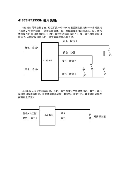
色 防区 2
4293SN 安装使用非常简单,红色、黑色两线接主机总线回路,黄色、黑色 端接常闭探测器即可,注意使用时要固定(4293SN 非常小巧,甚至可以固定在 探测器盒子里)
总线+(红色) 总线-(黑色)
4293SN
黄色 黑色 常闭探测器
4193SN/4293SN 使用说明:
4193SN 用于总线扩充, 可以扩展一个 10K 电阻监测的回路和一个常闭回路 (或者 2 个常闭回路) ,连接安装简便:红、黑线端接主机总线回路,白、黑色 线组成 10K 电阻监测防区 1(黄、黑线组成常闭防区 1) ,绿、黑色线组成常闭 防区 2。4193SN 结构小巧,可安装在探测器盒子里。 白色 红色 总线+ 黄色 4193SN 防区 防区 1
AIT ARINC429测试仪和分析仪产品说明书

ARINC 429Product OverviewAvionics Interface Technologies3703N.200th StreetOmaha,NE 68022Tel:+1402.763.9644Fax:+1402.763.9645ARINC 429TEST INSTRUMENTATION AIT's ARINC 429hardware modules for PXI,PCI,PCI Express,VME,and VXI provide advanced features and functionality to support even the most demanding test and simulation applications.•Four,eight,16,or 32software programmable Tx/Rx channels •Programmable high/low speed operation •Concurrent operation of all Tx/Rx channels •Full error injection and detection •Cyclic (rate‐oriented)and acyclic label transmissions •Block label transmissions •Label selective trigger for capture/filtering •Real‐time recording and post analysis of multiple channels •In‐line data corruption •Complete Software Development Kit (SDK)providing Device Drivers and APIs for C,C++,C#,,and LabVIEWARINC 429ANALYZERS AIT provides complete ARINC 429Analyzer and Data Acquisition solutions with the Flight Simulyzer ™application software.AIT's Flight Simulyzer ™is an intuitive and easy‐to‐use Graphical User Interface (GUI)that allows users to capture and analyzer ARINC data.Additionally,it supports simulation and generation of ARINC 429traffic including error injection.Flight Simulyzer ™can be used in conjunction with the AIT ARINC 429USB module to provide a portable analyzer and simulator solution.Together with the AIT PCI and PXI modules,Flight Simulyzer ™can be used to provide a desktop PC solution.RUGGED/EMBEDDED SOLUTIONS AIT's ARINC 429PMC,XMC,and PC/104+modules are rugged,reliable,full‐featured interface modules designed to provide dependable ARINC 429interfaces in the harshest environments.The rugged interface modules are provided with conduction cooled,extended temperature,and conformal coating options.Additionally,they are supported with RTOS (VxWorks,LynxOS,and others)device drivers and APIs.The AIT family of ARINC 429products provide solutions for Test Instrumentation,Data Acquisition,Protocol Analysis,and Rugged/Embeddedapplications.To buy, sell, rent or trade-in this product please click on the link below:/Avionics-Interface-Tech-AIT-USB-429-4-Data-Transfer-Unit.aspx COMPLETE ARINC429SOLUTIONSAIT proudly provides the industry’s most capable ARINC429products coupled with market‐leading customer support to ensure your long‐term success!ADVANCED MONITORING&DATA ACQUISITIONWith large amounts of on‐board memory(128MB),an IRIG B time encoder/decoder for external clock synchronization,and a flexible triggering and filtering engine,the AIT ARINC429modules provide an advanced monitoring and data acquisition solution.•High channel density with full monitoring of up to 32channels concurrently(Up to64channels for VXI and VME modules)•Hardware timestamping of all receives data with1 ms resolution,with independent on0board clock orsync to ecternal IRIG‐B input•Complex software configurable triggers and filters •Full error detection•Simultaneously receive data to chronological bus monitor and Label/SDI‐specific buffersIN‐LINE DATA CORRUPTIONLink any receive channel to any transmit channel to provide a“pass through”data channel.Supports operation as an in‐line data analyzer.Also,data corruption operations can be defined to selectively modify ARINC429label data to inject errors prior to re‐transmission.HIGH QUALITY HARDWARE MODULESAIT’s ARINC429modules utilize an FPGA based architecture to provide a flexible ARINC429compliant protocol engine which is also capable of supporting low level error injection and detection and which can easily support program‐specific customizations when required. With years of experience supporting aerospace applications,AIT understands the importance of supporting the entire life span of programs and is committed to obsolescence mitigations as well as consistent,reliable,on‐time product delivery.All AIT ARINC429modules are designed and manufactured in accordance with AS9100Rev C and ISO 9001:2008compliant processes.FLEXIBLE,HIGH‐PERFORMANCE OUTPUTThe AIT FPGA based ARINC429protocol engine provides flexible and efficient output operations:•Autonomous operation of labels,in rate‐oriented and block transfer modes of operation•Acyclic(on command)label transmissionconcurrently with scheduled output•Full error injection for each label transfer including short gap,parity,bit count,encoding•Multi‐buffering with real‐time buffer updates •Programmable gap time between labels •Programmable selection of High/Low speed operations on all channels•Industry’s highest channel density with up to32 fully operational concurrently operating channels(Up to64channels for VXI and VMEmodules!)/429******************AIT’s ARINC 429SOFTWARE DEVELOPMENT KITAIT’s ARINC 429SDK provides a complete suite of software tools and APIs to support intuitive and effective use of the features and functions of the AIT ARINC 429hardware modules.MULTIPLE OPERATING SYSTEMS The ARINC 429SDK provides Drivers and APIs for a variety of Operating System platforms:•Microsoft Windows XP and Windows 7•Linux •VxWorks •LabVIEW Real‐Time •Other RTOS’s on request (LynxOS,Integrity,...)MULTIPLE PROGRAMMING LANGUAGES Whether your integrating the AIT ARINC 429solutions into a legacy C based application or using the latest .NET or LabVIEW application development environments,we’ve got you covered with APIs for:•ANSI C •C++/Visual C++•C#• •LabVIEW (VIs)EASY INTEGRATION The ARINC 429SDK is built around a common ARINC 429Configuration Data core format which allows application designers to specify ARINC 429output and input configurations (e.g.output label transmit rates,input label filters,...)using an intuitive XML format which is formally defined in an XML Schema.This common configuration data format can be used to configure AIT's Flight Simulyzer analyzer application,the LabVIEW Instrument Driver component of the SDK,as well as the C++,C#,and software APIs.INTUITIVE &EASY‐TO‐USE ANALYZER AIT’s Flight Simulyzer ™is a Graphical User Interface (GUI)application that is easy to use and ready to go,right out of the box.It allows you to start capturing,analyzing,and simulating ARINC 429data on multiple channels in just a few clicks.Additional key features of Flight Simulyzer ™include:•Capture and analyze data from multiple ARINC 429input channels •Define and execute complex simulations of multiple rate‐oriented Labels •Simulate output data on multiple channels •Receive data to Label/SDI specific buffers •Send Acyclic Labels on command •Update,Modify,View ARINC 429data on‐the‐fly •Multi‐protocol support,capture,analyze,and simulate MIL‐STD‐1553bus dataLabVIEW Real‐Time INSTRUMENT DRIVER The ARINC 429SDK includes AIT’s ARINC 429LabVIEW Instrument Driver which is an easy to use driver that has been certified Compatible with LabVIEW and distinguished as a best‐in‐class add‐on product.The driver has been tested and verified,by National Instruments,to properly integrate withLabVIEW.Avionics Interface Technologies 3703N.200th Street Omaha,NE 68022Tel:+1402.763.9644Fax:+1402.763.9645/429******************3Nov 2014Doc No.40308001v01.01.01©2014Avionics Interface Technologies。
VISTA-128 主机进入编程手册

电话通讯部分编程:进入主机编程:41408000*93 0 0 1,进入报告码设置菜单(RERORT CODE PROG),0 1,进入REST,SUPV.CODE?输入001*01*01*01*01*01,输入000*,退出REST,SUPV.CODE? 0 1,进入SYSTEM GROUP #1?输入11*11*11*11*11*11*11*11*11*11*11*11*11*11*11*11*11*11*11*11* 0 1 进入SYSTEM GROUP #2?输入11*11*11*11*11*11*11*11*11*11* 0 1进入SYSTEM GROUP #3?输入11*11*11*11*11*11*11*11*11*11*11*11*11*11*11*11* 0 1进入SYSTEM GROUP #4?11*11*11*11* 1 1 退出报告码编程。
*09 进入延时#1,*10 外出延时#1,*11进入延时#2,*12 外出延时#2*13 警号发声时间设置*31 电话外线号码设置,没有不需要输入*32 主账号设置例如1234 输入01020304**33 主电话设置例如市局84209971**34 第二电话号码设置例如工行中心52344689**45 第一通讯格式输入1*47 第二通讯格式输入1*51双报告输入1*90第二通讯账号设置例如用户编号8888 ,输入08080808**39 输入1*45输入1*79输入1 1 1 1 1 1 1 1*80输入1 1 1 1*84 输入00;*88输入00若系统有多个子系统,责需要输入*91,跳转到不通的子系统。
*32*90防区编程部分41408000 进入主机编程1. 主机自身防区编程:在防区编程时应该有子系统的规划,就是每个子系统应该包含哪些防区。
这样在防区编程时就方便了。
2. 进入编程后显示:按*93 进入菜单编程,输入1 按*号确认进入下一步显示 "ZONE PROG?"输入1进入防区编程。
4193SN模块操作说明书
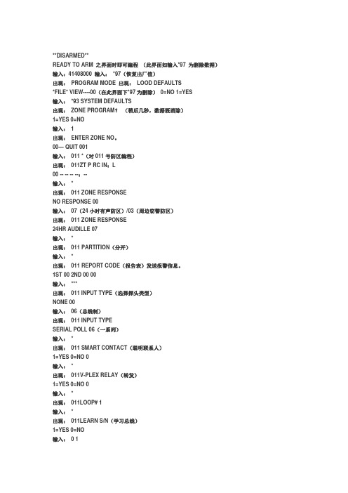
**DISARMED**READY TO ARM 之界面时即可编程(此界面如输入*97 为删除数据)输入:41408000 输入:*97(恢复出厂值)出现:PROGRAM MODE 出现:LOOD DEFAULTS*FILE* VIEW----00(在此界面下*97为删除)0=NO 1=YES输入:*93 SYSTEM DEFAULTS出现:ZONE PROGRAM?(稍后几秒,数据既消除)1=YES 0=NO输入: 1出现:ENTER ZONE NO。
00— QUIT 001输入:011 *(对011号防区编程)出现:011ZT P RC IN:L00 -- -- -- --:--输入:*出现:011 ZONE RESPONSENO RESPONSE 00输入:07(24小时有声防区)/03(周边窃警防区)出现:011 ZONE RESPONSE24HR AUDILLE 07输入:*出现:011 PARTITION(分开)输入:*出现:011 REPORT CODE(报告表)发送报警信息。
1ST 00 2ND 00 00输入:***出现:011 INPUT TYPE(选择探头类型)NONE 00输入:06(总线制)出现:011 INPUT TYPESERIAL POLL 06(一系列)输入:*出现:011 SMART CONTACT(聪明联系人)1=YES 0=NO 0输入:*出现:011V-PLEX RELAY(转发)1=YES 0=NO 0输入:*出现:011LOOP# 1输入:*出现:011LEARN S/N(学习总线)1=YES 0=NO输入:0 1出现:028LOOP# 011 INPUT SINNONE A xxxx---xxxx输入:*出现:028 DELETE 此时把“4293SN”模块的“十一”脚(红、兰)第24 。
25上,接触数秒,听到“嘀1=YES 0=NO,输入: 1出现:011CONFIRM SL1 嘀”声后,屏幕上显示该A095-1566 1(模块上的码)“42935N”的序列号。
HS-429产品用户指南说明书
1QM034 Issue 1HS-429 Vibration Trip Manual2 QM034 Issue 1CONTENTS1. SAFETY INSTRUCTIONS ------------------------------------------------------------------------- 42. FUNCTIONS AND FEATURES ------------------------------------------------------------------- 43. INSTALLATION -------------------------------------------------------------------------------------- 44. ELECTRICAL CONNECTION -------------------------------------------------------------------- 55. SETTINGS ---------------------------------------------------------------------------------------------- 56. SWITCHING AND BEHAVIOUR ---------------------------------------------------------------- 58. OPERATING AND DISPLAY ELEMENTS ---------------------------------------------------- 69. MAINTENANCE, REPAIR AND DISPOSAL -------------------------------------------------- 710. TECHNICAL PERFORMANCE ----------------------------------------------------------------- 811. ELECTRICAL ----------------------------------------------------------------------------------------812. MECHANICAL ---------------------------------------------------------------------------------------813. ENVIRONMENTAL ---------------------------------------------------------------------------------814. CABLE ASSEMBLY DETAILS -------------------------------------------------------------------9 3 QM034 Issue 14QM034 Issue 1An instruction is indicated by "►":Example: ► Check whether the unit operates correctly.Important noteNon-compliance can result in malfunctions or interferenceInformationSupplementary note1. SAFEY INSTRUCTIONS•Please read the product description prior to set-up of the unit Ensure that the product is suitable for your application without any restrictions •The unit conforms to the relevant regulations and EC directives. •Improper or non-intended use may lead to malfunctions of the unit or to unwanted effects in your application • That is why installation, electrical connection, set-up, operation and maintenance of theunit must only be carried out by qualified personnel authorised by the machine operator2. FUNCTIONS AND FEATURESThe vibration sensor detects the vibration in the system (measured / evaluated physical unit = vibration velocity) This is converted into an analogue signal at the current output The switching output behaviour is determined using the two setting rings3. INSTALLATION► Mount only in a thick housing wall (e.g. transport thread).► Ensure that the signal direction is correct► Ensure a safe vibration transmission and allow no elastic intermediate layers►Tighten the sensor with a tightening torque of 15 Nm5QM034 Issue 14. ELECTRICAL CONNECTIONThe unit must be connected by a qualified electrician. The national and international regulations for the installation of electrical equipment must be adhered to.5. SETTINGSRMS SetEffective value of the switching threshold, defining the limit value of the vibration velocity Delay SetTime in seconds during which the limit value must be effectively above the switching threshold (RMS Set) to activate the switching output (normally closed pin 4)6. MEASUREMENT RANGE7.SWITCHING OUTPUT BEHAVIOUR1: Time delay after the switching threshold has been exceeded2: Time delay after the switching threshold has been exceeded3: Switch-off4: Switching threshold5: DelayV ss = vibrationvelocity t = timeImplementation of the time delaysThe time delay starts when the defined switching threshold is exceeded (1) / (2)The time delay is cancelled when the value falls below the switching threshold (withoutswitch-off) The switch-off is triggered when the switching threshold is exceeded during a full time delay (3)6 QM034 Issue 17QM034 Issue 18. OPERATING AND DISPLAY ELEMENTS1) locking ring2) setting rings (manually adjustable after unlocking)3) LED green: voltage supply4) M8 process connection5) LED yellow: lights when switching threshold and time delay are exceeded6) setting marksTo achieve the setting accuracy: first position the rings to the lower end stop value, then set the requested value9.MAINTENANCE, REPAIR AND DISPOSALThe operation of the unit is maintenance-free. It is not possible to repair the unit. After use dispose of the unit in an environmentally friendly way in accordance with the applicable national regulations.10.TECHNICAL PERFORMANCEVelocity Ranges: to be specified with order, ±10% Nominal 80Hz at 22°C Frequency response: 10Hz (600cpm) to 1kHz (60kcpm) ± 5% - ISO10816False Trigger Delay: Adjustable up to 60 secondsTrip Setting: Fully adjustable11.ELECTRICALCurrent Output: 4-20mA DC proportional to Velocity RangeSupply Voltage: 18-32 Volts DCSwitching Output: NC, PNP up to 500mADisplay OK LED: GreenTrip LED: YellowCurrent Consumption: 18-30volts DC at 50mA12.MECHANICALCase Material: Stainless Steel 316L/PlasticMounting Torque: 15NmWeight: 116gms (nominal)Screened Cable Assembly: HS-AC010 (straight), HS-AC011 (right angle)Mounting Threads: M8 x 1.25mm male13.ENVIRONMENTALOperating Temperature Range: -25 to 80ºCSealing: IP67Maximum Shock: 100gEMC: EN61326-1:2013Reverse Polarity: ProtectedMTBF: 510 years8 QM034 Issue 1。
Agilent 4294A精确阻抗分析操作手册

安全总结 (7)1、安装 (9)1。
1设置和替换保险丝 (9)1。
2电源要求 (9)1.3电缆线 (9)1。
4连接BNC适配器(仅选项1D5) (9)1.5使用局域网(LAN)端口 (9)1.6连接提供的键盘 (9)1.7使用支架式装配工具 (9)1。
8环境要求 (9)1.9安装地点提供空旷地来散热 (9)1。
10清洁指南 (10)2、学习操作基础 (11)2。
1必需的仪器 (11)2.2测量的准备 (11)2.2.1连接 Agilent 16047 E 测试夹具 (11)2.2。
2打开电源 (11)2.2.3将适配器类型设定为“None" (12)2。
3叙述测量条件 (12)2.3.1初始化 Agilent 4294 A 到初始状态 (12)2.3。
2选择|Z|-θ作为测量叁数 (12)2.3.3扫描参数选择频率 (12)2。
3.4选择对数的扫描作为扫描类型 (12)2.3.5设置扫描开始频率为100HZ (13)2。
3。
6设置扫描结束频率为100MHZ (13)2。
3.7设定测量带宽值为 2 (13)2.4夹具补偿 (13)2。
4。
1开路状态的夹具补偿 (13)2。
4。
2短路状态的夹具补偿 (13)2。
5实行测量并且观察结果 (14)2.5。
1连接 DUT (14)2。
5.2给纵轴|Z|应用对数的格式 (15)2。
5.3给纵轴θ应用线性格式 (15)2。
5.4平行显示|Z|和θ的图 (15)2.5.5设置|Z|迹为自动调整刻度 (16)2。
5.6设置θ迹为自动调整刻度 (16)2.6结果分析 (16)2.6。
1确定Self—resonance Frequency 和Resonant Impedance (16)3、前/后面板、LCD显示屏 (17)3.1前面板 (17)3.1.1Hardkeys (18)1. 设置当前激活的通道的键区 (18)2。
测量功能的键区 (18)3. 与激励有关的键区 (19)4. 数字输入键区 (19)5. 关于定位记号功能的键区 (19)6. 关于仪器状态的键区 (20)7。
- 1、下载文档前请自行甄别文档内容的完整性,平台不提供额外的编辑、内容补充、找答案等附加服务。
- 2、"仅部分预览"的文档,不可在线预览部分如存在完整性等问题,可反馈申请退款(可完整预览的文档不适用该条件!)。
- 3、如文档侵犯您的权益,请联系客服反馈,我们会尽快为您处理(人工客服工作时间:9:00-18:30)。
4193(4293)使用编程说明书
4193SN用于总线扩充,可以扩展一个10K电阻监测的回路和一个常闭回路,连接安装简便:红、黑线端接主机总线回路,白、黄色线组成10K电阻监测防区1,绿、黑色线组成常闭防区2。
4193结构小巧,可安装在探测器盒子里。
4293SN安装使用非常简单,红色、黑色两线接主机总线回路,黄色、黑色端接常闭探测器即可,注意使用时要固定(4293非常小巧,甚至可以固定在探测器盒子里)
4193(4293)防区编程:
进入编程模式
输入4140 8000 (4140为出厂设置的安装员密码)
进入编程模式后键盘显示:Program Mode
*Fill # View 0
按*93 键盘显示:ZONE PROG。
?
1=YES 0=NO 0
输入0进入下一命令项。
键盘显示:EXPERT MODE ?
选择编程模式:输入1为快速编程模式1=YES 0=NO 0
在这里选择“1”键盘显示:Set to Confirm?
1=YES 0=NO 0
输入1进入快速编程后主机显示:(以10防区为列此为编好后的显示)
Z N Z T P RC INL
010 03 1 10 SL 1S
Z N 表示防区号 Z T表示防区类型 P表示子系统号 RC表示报告码 INL表示接入方式
Z N:要编辑防区的防区号,4208SN的防区属于总线防区,需要从“10”防区开始编
前面1-9是分线制的基础防区。
Z T:选择防区类型(请根据具体情况输入防区类型)的编号如下:
*编号01—出入口防区1型,布防时有延时,进入时有延时,延时时间由编程项“09”和“10”设定;
编号02—出入口防区2型,布防时有延时,进入时有延时,延时时间由编程项“11”和“12”设定;
*编号03—周边防区,布防时有效,撤防时无效;(即时防区类型)
编号04—内部防区,留守布防时无效,外出布防时有效,撤防时无效;
编号06—24小时无声防区;
*编号07—24小时有声防区;
编号09—火警防区;
编号00—无用防区。
以上标有“*”号的类型为常用防区类型,其他防区类型请参照英文手册。
我们在这里把010防区编程为周界防区(即时防区)类型
P:如果主机分了子系统那么就输入此防区相对应的子系统号,如未分则输入“1”
RC:为报告码项,如无要求可以不用编辑。
INL:接入设备类型:
此项设定010防区的接入设备类型,请输入防区接入设备类型的编号:在这里我们选择06类型。
设备类型见下表:
这里设备是4208SN 所以我们在INL处输入“06”则自动变为了“SL”
然后按“*”确认进入下一项显示如下:
Z N B M V ACE AD
010 - 0 0 00- - -
然后按“*”确认进入下一项显示如下:
010 Input S/N:L
A ×××-××××:1
输入8防区扩充模块(4208SN)“01”地址第一防区7位序列号(006-5540),后面一位数字“1”表示回路号,4208SN每一个回路都输入“1”。
(双防区模块4193SN:黄色线为第1回路,输入“1”;绿色线为第2回路,输入“2”;白色线也为2回路必须加10K电阻,而且绿色线不能作为第2回路用)
按“*”键盘显示:Xmit To Confirm
Press *to skip
按“*”显示如下:
Z N Z T P RC INL
011 00 1 10 00
此时进入“011”防区的编程,如果要退出则在Z N下的“011”处输入“000”
然后按“*”退出后显示如下:
QUIT MENU MODE?
1=YES 0=NO 0
输入“1”键盘显示:Program Mode
*Fill # View 00
按*99主机重启
注意:在主机才加电时和退出编程时,主机有个大约2分钟的自检时间
在此时间段内主机检测不到防区的任何问题。
4193(4293)总线模块检测方法:
把前端探头全部取掉,直接将模块接入总线上,然后进去防区编程模式然后到
如下所示的步骤:
010 Input S/N:L
A ×××-××××:1
然后将防区模块的黄(绿),黑端触发下,看在A ×××-××××:1处有无
地址码显示出来。
