EM600S96-T多功能电力仪表
DW9T系列三相智能电量仪表说明书
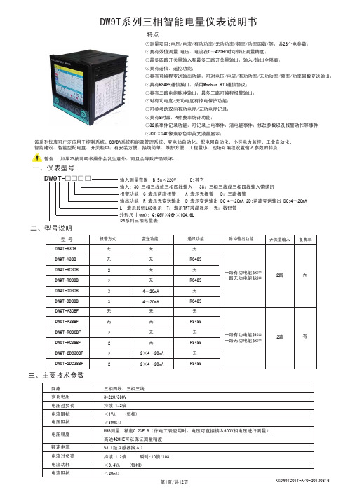
该系列仪表可广泛应用于控制系统、SCADA系统和能源管理系统、变电站自动化、配电网自动化、小区电力监控、工业自动化、智能建筑、智能型配电盘、开关柜中;有安装方便、接线简单、维护方便、工程量小、现场可编程设置输入参数的特点。
警告 如果不按说明书操作会发生意外,而且会导致产品毁坏。
DW9T系列三相智能电量仪表说明书⊙测量项目:电压/电流/有功功率/无功功率/频率/功率因数/等,共28个电参数;⊙真有效值测量,电压、电流在0~420HZ时可保证测量精度;⊙最多四路开关量输入和最多三路开关量输出,输入/输出全隔离;⊙具有遥信、遥控功能;⊙具有可编程变送输出功能,可对电压/电流/有功功率/无功功率/频率/功率因数变送输出;⊙具有RS485通信接口,采用Modbus RTU通信协议;⊙具有二路电能脉冲输出,最多三路可编程报警输出;⊙对有功电度/无功电度有掉电保护功能;⊙可参考的双向有功电度/无功电度记录;⊙具有8时段,4种费率统计功能;⊙32条事件记录功能,可记录上电事件,清电能事件,修改参数以及报警动作等事件;⊙320×240像素彩色中英文液晶显示;特点一、仪表型号三、主要技术参数输入测量范围: B:5A×220V D:其它输入: 30:三相三线或三相四线输入 38:三相三线或三相四线输入带通讯 报警功能: C:表示两路报警 A:表示无报警 D:三路报警输出功能: R:表示无变送输出 D:表示变送输出 DC 4~20mA 2D:两路变送输出 DC:4~20mA DW系列三相电量表□□□□-DW9T 二、型号说明外形尺寸(mm): 9:96W×96H×104.6L L:表示段码LCD显示 T:表示TFT液晶显示 无:数码管 无RS485 无 RS485 无RS485无无 无 无 无 无报警方式脉冲输出功能变送功能 通讯功能 开关量输入 复费率DW9T-A30B DW9T-A38B DW9T-RC30B DW9T-RC38B DW9T-DD30B DW9T-DD38B 型 号22332路无无RS485 无 RS485 无RS485无无 无 无 无 无DW9T-A30BF DW9T-A38BF DW9T-RC30BF DW9T-RC38BF DW9T-2DC30BF DW9T-2DC38BF22222路有三相四线、三相三线3*220/380V 持续:1.2倍<1VA (每相)≥300K ΩRMS测量 精度0.2%F.S(作电工表应用时,电压可直接接入600V相电压进行测量),高达420HZ可以保证测量精度5A(经互感器接入)持续:1.2倍 瞬时:10倍/10S <0.4VA (每相)<20m Ω4~20mA 4~20mA 2×4~20mA 2×4~20mA一路有功电能脉冲一路无功电能脉冲一路有功电能脉冲一路无功电能脉冲电流阻抗电流功耗参比电压网络电流阻抗电压过负荷电压精度电压阻抗额定电流电流过负荷四、面板说明五、菜单修改说明查看测量值及仪表工作状态说明:复费率(使能情况下)等界面切换显示。
916 全触控智能型滴定仪

916 Ti-Touch 精灵一代瑞士万通新一代一体式电位滴定仪,日常样品分析的得力助手✧系统整合度最高,外观设计简约时尚✧多思TM Dosino加液单元技术,保障用户使用安全性✧丰富可选的爱·智能TM电极✧可扩展为双通道滴定✧U盘存储防伪PDF实验报告,网络传输✧包括中文在内的多种对话语言916 Ti-Touch 精灵一代一体式电位滴定仪便,根据您的应用领域,瑞士万通诚意为您提供以下三种标准配置916 Ti-Touch食品分析包,存储器或条形码阅读器接口,可进行双通道滴定,提升工作效率加液器搅拌力度根据样品粘稠度自动调整为设定速度•免拆卸“零”接触,进行试剂更换获得专利设计的多思TM Dosino加液单元技术,使得试剂的更换更加方便,避免了与有毒有害试剂的接触•丰富的爱·智能TM电极,满足不同实验需求可以长距离传输信号及数据不会受到周围环境磁辐射信号的干扰信号更稳定更灵敏更准确使用寿命更长•自动监控不正常的实验结果系统所有组件以及实验结果都可以进行监控,对于不正常的数据给出明显提示•tiBase数据处理软件,实现完善的工作将实验结果存入USB 存储器或网络电脑中,可导入至tiBase数据处理软件中进行数据管理•无纸化办公,PDF报告可生成防伪的PDF 实验报告,并存储在USB 存储器或网络电脑中,时尚又环保•个性化触摸屏,快速调用实验方法可在触摸屏上创建14个快捷图标,直接调用方法进行实独创的多思TM Dosino 加液单元与爱·智能TM 滴定管单元的完美结合技术参数一览表。
福禄克用户手册

®
Fluke 123/124 Industrial ScopeMeter
CH 2002 年 9 月 Rev. 4, 09/2009Байду номын сангаас
© 2002, 2005, 2007, 2008, 2009 Fluke Corporation. 版权所有。 所有产品名称均为其所属公司的商标。
用户手册
有限保修及义务范围
在正常使用与维修情况下,Fluke 保证每一个产品无质地及工艺问题。自发货之日算起,测试工具保修期为三年,附件保修期为一年。零配件及产品修理与维护的 保修期为 90 天。此保修只限于原始购买者和 Fluke 指定经销商的产品使用客户保修不适用于保险丝和普通电池,亦不适用于任何 Fluke 认为因错误使用、改装、 疏忽或因事故或非正常条件下操作或处置而导致损坏之产品。在 90 天内,Fluke 保证软件运转符合功能规范,且保证软件正确录制于完好无损的介质上。Fluke 不保证软件毫无差错或无操作中断情况。
或者与下列任何电话联系: 在美国与加拿大:+1-888-993-5853
在欧洲:+31-402-675-200 从其它国家:+1-425-446-5500
正弦(EM600系列高性能矢量变频器用户指南V110
前言感谢您选用正弦电气EM600系列高性能矢量变频器。
资料编号:31010040发布时间:2018-7版本:110EM600系列变频器是正弦电气推出的高性能矢量控制型变频器:支持三相交流异步电机和永磁同步电机;支持多种国际领先驱动控制技术——改善的矢量VF控制技术(VVF)、无速度传感器矢量控制技术(SVC)和有速度传感器矢量控制技术(FVC);支持速度和转矩两种输出形式;支持扩展——I/O 扩展卡、通讯总线扩展卡和多种PG卡。
EM600系列高性能矢量变频器有如下特点:●从11kW开始内置直流电抗器,减小输入电流畸变,提高功率因数,增强产品可靠性;●转矩控制精度高:SVC/±8%额定转矩、FVC/±5%额定转矩;●调速范围宽,控制精度高:VF/1:50、SVC/1:200、FVC/1:1000,±0.2%额定转速;●低频带载:VVF/1Hz/150%、SVC/0.25Hz/150%、FVC/0Hz/150%;●过压失速、快速限流、过载、过热、掉载、超速等多重保障;●支持I/O扩展:4路数字输入、1路数字输出、1路-10V~10V电压型输入;●支持通讯总线扩展,实现各种工业网互联:485总线、Profibus-DP网络、CANopen网络和DeviceNet网络;●支持多种编码器:ABZ增量式、UVW增量式、UVW省线式和旋转变压器。
在使用EM600系列高性能矢量变频器之前,请您仔细阅读本指南,并请妥善保存。
变频器首次与电机连接时,请您正确选择电机类型(异步机或同步机),并设定电机铭牌参数:额定功率、额定电压、额定电流、额定频率、额定转速、电机接法及额定功率因数等。
若为FVC驱动控制方式,需选配PG卡,并正确设置编码器参数。
由于我们始终致力于产品和产品资料的完善,因此,本公司提供的资料如有变动,恕不另行通知。
安全注意事项安全定义:在本手册中,安全注意事项分以下两类;危险:由于没有按要求操作造成的危险,可能导致重伤,甚至死亡的情况。
GEC系列产品2011样册

38
GEC2000 Series Intelligent Network Electric Meter
42
GEC3000 Series Intelligent Relay and Supervisory Unit
订货信息 43 快速选型 44 工程业绩 46
43 Ordering Information 45 Quick Selection Table 51 Engineering Performance
系统解决方案 10 供配电综合保护监控及节能管理系统 15
GEC2000 系列智能网络电力仪表 23 GEC3000 系列电力微机保护单元 39
14 System Design Strategy
22
Electric Supervisory Control and Energy Conservation System
设计选型手册
(2011 版)
中英合资企业
客户端安全监控与 节能“CT”管理时代的开创者与领导者
The pioneer and leader of CT-style management era of client safety monitoring and energy saving
目 录 Contents
本手册版权归佳和电气所有,未经允许,严禁复制、引用或翻译。本手册包含信息均为佳和电气提供, 产品照片及说明仅供参考,如需了解产品详细信息敬请垂询。所有信息的最终解释权归佳和电气所有。
2011
配 电 监 控 及 分 项 计 量 节 能 管 理 系 统
设 计 选 型 手 册
配电监控及分项计量节能管理系统
GAEA Electric system solution has been widely applied in various fields such as municipal construction,power,petro-chemical,commerce,heavy industry, aviation,and traffic and its representative project such as Zhejiang provincial government building,Shanghai World Expo,municipal projects of reconstruction of stricken areas,Xixi Paradise,Datang International,Yanchang Petroleum,Ningbo Tianyi Square,CITIC Heavy Industries,Aviation 618 Agency,Hangzhou-Qiandaohu Highway and Jinjiang Group.And it has become the supplier of high-end product system for various large-scale power clients in the country.
963E 静电消除机安装、使用与维护指南说明书

963E-NO963E-XDescriptionThe SCS 963E Benchtop Air Ionizer is a self-contained ionizing air blower designed to remove static charges from non-conductive objects. The proprietary circuitry contained in the blower generates balanced levels of positive and negative ions. The Ionizer is equipped with a two speed fan which allows the user to select the amount of ionized air to be delivered to the target object. The Benchtop Air Ionizer meets the required limits of ANSI/ESD S20.20 tested per ANSI/ESD STM3.1 or ESD TR53.PerformanceThe Benchtop Air Ionizer reduces a static charge of ± 1000V to ± 100V in less than two seconds (the discharge time) at a distance of one foot (30 cm) using the high fan speed. Testing is performed in accordance with the ionization standard ANSI/ESD STM3.1.Power RequirementsThe Benchtop Air Ionizer requires 24VDC power, which is supplied through a Mini DIN connector on the back of Figure 1. SCS 963E Benchtop Air IonizerThe SCS 963E Benchtop Air Ionizer is available in two Benchtop Air Ionizer, North America Benchtop Air Ionizer, EuropeSCS offers the following accessory for the Benchtop Air Power Adapter, 110-240VAC Input, 24VDC Output, No Power CordThe Benchtop Air Ionizer mounts easily in a variety of positions using the provided tilting bracket/stand. Place the unit on the work surface and point it at the area or object to be neutralized. Alternatively, the mounting bracket may be attached directly to or above the workstation, or on another supporting structure. Note that placement of the Ionizer is important in determining its effectiveness. The distance from the target object, and fan speed affect the ionizer’s performance. As distance increases or fan speed is reduced, the Connect the switching power supply to the Ionizer using the Mini DIN connector. Then, using the appropriate electrical power cord, connect the switching power The three position rocker switch on the front of the unit is the POWER switch. The center switch position (marked O) is the OFF position. The upper and lower switch positions (marked II and I) turn the unit on to HIGH and LOW fan speeds. Use this switch to turn the unit on and to select the desired fan speed. A green monitor light is also illuminated respectively on the front of the unit, which indicates that the power switch is in one of the ON positions, and that the ionizer is now inMaintenanceOccasional cleaning of the case and of the emitter points are the only routine maintenance procedures required.Cleaning the caseWipe the case with a soft cloth moistened with water. If a stronger cleaning solution is required, mild detergent or alcohol may be used. Do not use solvents that will attack the plastic case.Cleaning the emitter pointsMAKE SURE TO REMOVE ELECTRICAL POWER FROM THE IONIZER. The emitter points are located between the fan blades and the rear grill. A jet of clean, compressed air can be used to remove dirt on emitter points. If a more rigorous cleaning method is needed to remove particulate, clean the points with a cotton swab. Access to the points is available through the rear grill. Be careful not to damage the points during cleaning.Performance VerificationThe SCS Benchtop Air Ionizer is factory adjusted to provide optimum performance. Further adjustment in the field is not possible. However, the following instructions can be followed to determine whether the Ionizer is performing to specifications. The testing follows the procedure outlined in the standard for Ionization, ANSI/ ESD STM3.1. Please refer to this standard for more complete information.Equipment NeededSCS 711 Charge Analyzer or equivalent charge plate monitor (CPM). If an alternate CPM is used, please refer to its Operating Manual for details on how to perform the following instructions.Static Discharge TimeThe Ionizer will reduce the charge on the 6" x 6" square isolated metal plate on the CPM from ± 1000V to ±100V in less than 2 seconds (high fan speed). The metal plate for the CPM must be located at a distance of one foot (30 cm) from the ionizer and centered in the air stream.Attach the flat plate electrode to the Charge Analyzer. Place the Charge Analyzer on its side allowing for viewing of the display. Position the Charge Analyzer so that the plate is parallel to the ionizer at a distance of one foot. The plate of the Charge Analyzer should be centered (up and down, left and right) in the air stream. It may be necessary to raise the ionizer from the surface to allow for centering on the Charge Analyzer charge plate. If so, use a block of appropriate heightto elevate the Charge Analyzer. Please note that the plate must be kept totally isolated from ground and that the edge of the plate should be raised up a minimum distance of 3 in. from the work surface. Reference ANSI/ ESD-STM3.1.Turn on the ionizer at high speed and allow it to run for five minutes.Charge the plate positive as described in the Charge Analyzer operating instructions for “Static Decay Time” mode. Observe the discharge time indicated on the Charge Analyzer. Repeat this step for negative polarity. Ion BalanceThe ionized air blower will stay within an offset voltage of +15 volts (max. deviation from zero) at a distance of one foot, when measured using the following procedure. Position the ionizer and CPM as stated above.Turn on the ionizer at high speed and allow it to run for five minutes.Use a ground wire to ground the charge plate of the Charge Analyzer. This will remove any/all residual charge present on the charge plate. If the CPM does not zero, adjust the zero control.Remove the ground wire and observe the display on the Charge Analyzer. The voltage (either ±) observed during this time is the “offset voltage” and is a measure of instantaneous ion imbalances produced by the ionizer.SpecificationsPower Ratings24VDC, 0.42Athrough included universalpower transformerPower Inlets Mini DIN SocketPower Transformer Input: 100V–240VAC,0.8A, 50/60 Hz into IEC320SocketOutput: 24VDC, 1.0A6' (1.8m) cord with Mini DINplugDimensions(with mounting base)8.5" W x 9" H x 4.5" D(21.6 cm W x 22.9 cm H x11.4 cm D)Air Velocity**low speed - 100 fpm(0.5 m/s)high speed - 300 fpm(1.5 m/s)Static Discharge Time*@1 ft. (30 cm)< 2 secondsOffset Voltage (Balance)+ 15VCertifications andApprovalsCE, UL* When tested according to ANSI/ESD STM3.1 at high fan speed** Air Velocity tested at 1 ft. distance from center of fan to Anemometer963E-NO963E-X。
高度仪e0006故障最简单处理方法

高度仪e0006故障最简单处理方法嘿,朋友们!咱今天就来讲讲高度仪 e0006 故障最简单的处理办法。
这高度仪啊,有时候就跟那爱闹脾气的小孩子似的,突然就给你来点小毛病。
你说这高度仪 e0006 故障了,别着急上火,咱得冷静应对。
就像咱走路遇到个小坑,跨过去就完事儿了呗。
先看看是不是电源出问题啦。
这就好比人没吃饱饭没力气干活一样,高度仪没电了它也没法好好工作呀。
检查检查电源线,看看是不是没插好,或者电源插头是不是松了。
要是这小问题,那咱顺手一插紧,嘿,说不定就好啦!再瞧瞧是不是显示出问题了呀。
就好像咱眼睛花了看不清东西一样,高度仪的显示要是不清楚,那可不行。
看看屏幕是不是脏了,拿个干净软布擦一擦,也许一下子就清晰了呢。
还有啊,有时候可能是一些小零件松动了。
这就跟咱衣服上的扣子松了似的,得赶紧给它弄好。
把那些螺丝啥的都紧一紧,说不定故障就解决了。
要是这些办法都不行,那咱也别慌。
就好比走路遇到条河,咱得想法子过河呀。
可以找专业的人来瞧瞧嘛,人家是专家,肯定有办法。
我记得有一次啊,我那高度仪就出了 e0006 故障,我就按照我上面说的这些办法一个个试。
嘿,还真就被我给解决了。
当时那心情啊,就跟大热天吃了根冰棍儿一样爽!反正啊,遇到高度仪 e0006 故障别害怕,办法总比困难多。
咱就耐心点,仔细点,肯定能找到解决问题的办法。
电源、显示、零件,一个一个排查过去,总能找到原因的。
要是自己实在搞不定,那就赶紧找专业人士帮忙,可别自己瞎捣鼓把问题弄更严重了。
所以啊,朋友们,高度仪 e0006 故障并不可怕,咱有办法应对!就这么着,大家记住这些简单的处理方法,让咱的高度仪能一直好好工作!。
网络电力仪表品种及选型方法

网络电力仪表品种及选型方法
1、概述
安科瑞 徐孝峰 江苏安科瑞电器制造有限公司 江苏 江阴 214405
网络电力仪表是针对电力系统、工矿企业、公共设施、智能大厦的电力监控需求而设计
的。它能测量所有的常用电力参数,如三相电流、电压,有功、无功功率,电度、谐波等。
由于该电力仪表还具备完善的通信联网功能,所以我们称之为网络电力仪表。它非常适合于
� 可通讯接入 SCADA、PLC 系统中;可与业界多种软件通讯(Intouch, Fix, Citec,组态 网等);
� LED 或蓝屏背光 LCD 显示,可视度高; � 方便安装,接线简单,工程量小; � 仪表采用专用失电保护电路,在失电情况下,数据保存不丢失,恢复电源后,仪表继续
运行; � 四象限电能计量,分时计费,最大需量纪录及 12 个月电能统计。 � 功能
ACR10EFL、ACR100E、ACR110E、ACR120E、ACR120EL、ACR120EFL、ACR200K、ACR200ILH、
ACR200ULH、ACR200UILH、ACR200E、ACR210E、ACR220E、ACR220EL、ACR220EFL、ACR300E、
ACR310E、ACR320E、ACR320EL、ACR320ELH、ACR320EFLH、ACR330ELH、ACR410E、ACR420E、
EM600LCD数显仪表
产品简介多功能电力仪表用于配电系统的连续监视与控制。
可测量双回路三相电流、功率、电能和需量,以及一路母线三相电压。
具备4路数字量输入(DI),1路24V直流辅助电源输出。
所有数据都可以通过RS485通信口用Modbus®-RTU协议读出。
双回路多功能表将精确测量、智能化多功能和简单人机界面结合在一起。
多功能电力仪表,节省盘面空间,占用通信资源少,降低配电监控系统和能源管理系统的造价,用户在实现配电自动化和能源管理的同时节省大量投资。
应用领域|JingYinYaDa■能源管理系统■工业自动化■小区电力监控■变电站自动化■配电网自动化■智能建筑雅达电子2015最新款产品图面板显示:安装方法1).在固定的配电柜上,选择合适的地方开一个开孔尺寸的安装孔。
2).取出仪表,松开定位螺丝,取下固定夹。
3).将仪表安装插入配电柜的仪表孔中。
4).插入仪表的固定夹,固定定位螺丝。
注:L-N为辅助电源请按仪表外壳接线图正确接线!产品名称仪表接线图数显表说明书仪表开孔尺寸多功能测控仪表仪表接线图数显表说明书开孔:91*91智能电力监控仪表仪表接线图数显表说明书开孔:76*76综合电力监控仪仪表接线图数显表说明书开孔:67*67三相网络电力仪表仪表接线图数显表说明书开孔:45*45三相网络电力仪表仪表接线图数显表说明书开孔:91*45多功能谐波表仪表接线图数显表说明书开孔:111*111三相智能数字仪表仪表接线图数显表说明书江阴雅达电子单相智能数字仪表仪表接线图数显表说明书输入信号产品采用了每个测量通道单独采集的计算方式,保证了使用时完全一致、对称,其具有多种接线方式,适用于不同的负载形式。
接线图完整版|Dimensions辅助电源江阴雅达多功能电力仪表具备通用的(AC/DC)开关电源输入接口,若不作特殊声明,提供的是220V(AC/DC)或110V(AC/DC)电源接口的标准产品,仪表极限的工作电源电压为AC/DC:80-270V,请保证所提供的电源适用于该系列产品,以上防止损坏产品。
EM600LED数显仪表
应用领域|JingYinYaDa■能源管理系统■工业自动化■小区电力监控■变电站自动化■配电网自动化■智能建筑简介多功能电力仪表用于配电系统的连续监视与控制。
可测量双回路三相电流、功率、电能和需量,以及一路母线三相电压。
具备4路数字量输入(DI),1路24V直流辅助电源输出。
所有数据都可以通过RS485通信口用Modbus®-RTU协议读出。
双回路多功能表将精确测量、智能化多功能和简单人机界面结合在一起。
多功能电力仪表,节省盘面空间,占用通信资源少,降低配电监控系统和能源管理系统的造价,用户在实现配电自动化和能源管理的同时节省大量投资。
雅达电子2015最新款产品图面板显示:安装方法1).在固定的配电柜上,选择合适的地方开一个开孔尺寸的安装孔。
2).取出仪表,松开定位螺丝,取下固定夹。
3).将仪表安装插入配电柜的仪表孔中。
4).插入仪表的固定夹,固定定位螺丝。
注:L-N为辅助电源请按仪表外壳接线图正确接线!产品名称仪表接线图数显表说明书仪表开孔尺寸多功能测控仪表仪表接线图数显表说明书开孔:91*91智能电力监控仪表仪表接线图数显表说明书开孔:76*76综合电力监控仪仪表接线图数显表说明书开孔:67*67三相网络电力仪表仪表接线图数显表说明书开孔:45*45三相网络电力仪表仪表接线图数显表说明书开孔:91*45多功能谐波表仪表接线图数显表说明书开孔:111*111三相智能数字仪表仪表接线图数显表说明书江阴雅达电子单相智能数字仪表仪表接线图数显表说明书输入信号产品采用了每个测量通道单独采集的计算方式,保证了使用时完全一致、对称,其具有多种接线方式,适用于不同的负载形式。
接线图完整版|Dimensions辅助电源江阴雅达多功能电力仪表具备通用的(AC/DC)开关电源输入接口,若不作特殊声明,提供的是220V(AC/DC)或110V(AC/DC)电源接口的标准产品,仪表极限的工作电源电压为AC/DC:80-270V,请保证所提供的电源适用于该系列产品,以上防止损坏产品。
艾森xStorage Home单相6kW6kWh电池储能系统说明书
Eaton XSTH1P0602NBUEV2Eaton xStorage Home single-phase, 6 kW, 6 kWh, DC and AC coupled, Blue, PV 6Eaton xStorage Home single-phase XSTH1P0602NBUEV23553340100628890 mm 1230 mm 220 mm 159 kgCE Marked CE LVD RoHS CompliantEN 61000-6-3 EN 61000-6-2EN 62109 (part 1:2010, part 2:2011)XST 1Ph 6.0 kW 6 kWh BlueProduct NameCatalog Number EANProduct Length/Depth Product Height Product Width Product Weight Compliances Certifications Model Code0.99 (Grid-Tie), 0.8 (ind) - 0.8 (cap) (Grid Tie-PF regulation, Off-Grid)6 kW29 A230V97%Residual current circuit breaker (RCCB)Overload-/temperature protectionShort-circuit protectedBuilt-in batteryWith data loggingEthernetWLANEmergency power compatible6000 VA550 V20 AIP20Power metering of critical loads and PV production xStorage Home BrochureEaton xstorage Home Brochure enxStorage Home Product team guidelinesxStorage Home Installation manualEaton xStorage Home Quick Start Guide xStorage Home User Interface ManualEaton xStorage Home Safety Guidelines xStorage Home User manualHow to onboard xStorage Home into the Cloud xStorage Home - Technical data sheetOutput power factorPower rangeAC current - maxAC inputEfficiency (PV to grid) - max Fitted with:Nominal output powerDC voltage on PV input - max Input Current on PV Input – Max Degree of ProtectionLED indicator colorMetering capability BrochuresCase studiesManuals and user guidesMultimediaTechnical data sheetsGreen (ON): Normal status. Red (ON): Fault status. Inverter is unable to connect to the grid.Green (Blinking): Communication activitySpecial featuresThe xStorage Home system offers three different power inverter ranges.Nominal DC Operating Voltage – Max550 VCoolingNatural airflowStorage temperature - max40 °CTopologyTransformerlessBattery nominal capacity6 kWhProtective classIAC wiring systemsSingle phase/N/PE, TN, TT, IT (additional fuse or CB required)Relative humidity - min5 %C/D DC current - Max75 ANominal AC output current26 AStandby losses< 10WStorage temperature - min-10 °CDC battery voltage - min74.4 VOver voltage categoryOVC II (PV and Battery), OVC III (AC grid/load)PhaseSingle phaseOperating temperature - min0 °CRelative humidity - maxEfficiency (Battery to AC) - Max>90%Grid integrationDC and AC coupledNumber of MPPT Trackers2Noise level35 dB (indoor application)Rated MPP-voltage – min240 VMaterial coverPlasticNominal DC Operating Voltage – Min 100 VPower consumption6 kWOperating temperature - max30 °CHazard substance restrictionLead free, compliance with RoHS GP2Initial feeding voltage150 VProtocolRESTHTTPAPIMPPT efficiency> 99%Recommended PV power3 kWp - 7 kWpSolar DC switchYesNominal AC grid voltage230 V (Grid-Tie), 230 V ± 3 % (Off-Grid)DC battery voltage - max98.4 VEaton Corporation plc Eaton House30 Pembroke Road Dublin 4, Ireland © 2023 Eaton. All rights reserved. Eaton is a registered trademark.All other trademarks areproperty of their respectiveowners./socialmedia35 A Transformerless 90 V< 3%AC Synchronized operation 50 Hz / 60 Hz ± 1 Hz 2000 m Standard550 VTypeBattery voltage rating Total Harmonic Distortion (THD)Nominal frequencyAltitude Display Rated MPP-voltage – max。
维特克95X系列高性能高伏特淋测试仪说明书

Vitrek built the 95X series from the ground up with DSP technology—to bring you the safest, fastest, most capable, feature rich hipot testers available. The 95X series combines high output power, with a wide range of AC & DC voltage outputs and extremely low leakage current measurement. Then we added a 4-wire milli-ohmmeter with dynamic range up to 100K ohms and an overlapping Tera-ohm class Insulation Resistance function. Top that off with an available 40 Amp Ground Bond capability and you’re just beginning to get a feel for what theVitrek 95X Series Hipot Testers can do for you.95X SeriesUltra-High PerformanceHipot TestersPower and Versatility for your Most DemandingElectrical Safety Test ApplicationsVitrek 95X SeriesFor more than 25 years Vitrek has been driven by an obsession to build a better hipot tester. Increased user safety, faster test times,higher output voltages and more functionality have been our driving force. The 95X series is the result of this pursuit—offering power, speed, accuracy and resolution that leave the others far behind.can be configured to source up to 100mA or even as much as 200mA. For higher AC hipot voltages the 95X can generate up to 10KV internally and all models are available with an external 30KVAC hipot option.When it comes to making critical leakage current measurements, the 95X delivers rock-solid resolution down to 100 pico-amps. This high resolution provides built-in insulation resistance measurement (IR) up to a Tera-ohm, add a 4-wire milli-ohmmeter with autoranging up to 100K ohm and an available 40 amp Ground Bond function—and you are beginning to understand the versatility of the Vitrek 95X Series.Need To Hipot Multiple Test Points?The 95X has the ability to directly control up to four 64 channel HV scanners, right out of the box. That is up to 256 test points and using a PC with Vitrek’s QuickTest Pro software you can expand the count up to 640 test points. The HV Switching System of choice is the Vitrek 964i which can hold eight 8 channel switching cards—available in 7, 10 and 15 KV ratings. The 964i also has switching cards to handle routing up to 40 amp ground bond currents.95X SeriesIndustrial Strength Hipot T estersFor Demanding Hipot Tests –Demand the Vitrek 95XSpeed and power go hand in hand, the 6.5KVDC models offer 50mA of source current for DC Hipot—providing the power you need to rapidly charge and discharge challenging DUTs. Models are also available with DC hipot up to 11KV and 15KV. Most of the 95X series also offer 50mA of sourcing for AC hipot, but for heavier AC loads the 95XThe TL-UP2 Test Adaptor allows for easy Hipot and Ground Bound connection to virtually any device with a power cord. The TL-UP2 routes high voltage to both the line and neutral pins of the power socket and connects the earth pin of the socket to the return of the tester. A separate test lead can be connected to the DUT chassis for continuity or Ground Bond testing to the earth pin of the DUT power cord. Available in Hipot/Continuity or Hipot/ Ground Bond versions.More speed, more power, better resolution, more functionality.What more could you want in an electrical safety tester?2 of 7Features and Benefits• Highest Level of Operator Safety—features include: GFI High speed shut down for earth ground leakage faults, SFI™ Safety Fault Interlock – High speed shut down for interruption of safety interlock, TLSS™ Test Lead Safety Sense – Clamps DUT chassis near ground by continuously verifying proper connection of test leads prior to and during HV testing• High Power Output—means better drive capability and increased test throughout. With up to 50mA of sourcing current for DC hipot the 95X Series gets heavy duty jobs done fast—available 100mA & 200mA AC drive tackles even the toughest sourcing requirements• Wide Range of built-in Voltage Capabilities – Choose from 6.5KVDC,11KVDC or 15KVDC and 6KVAC, 10KVAC or up to 30KV RMS AC with external option • The Fastest Hipot Testers available– High output power combined with Dual Coldfire® microprocessors and Dual DSPs to provide Ramp rates up to 50KV/second, dwell times as low as 20mS and overall test times as fast as 3mS in optional Flash mode • Expansive Test Sequence Memoryholds up to 100 tests with up to 100 stepsper test. Tests can be selected via frontpanel, Ethernet, RS232, Digital I/O or withoptional GPIB• Ground Bond Test Capability availablein three models with output currents from100mA to 40Amps RMS and test timesfrom 20mS to 1000 seconds or longer• 4-Wire Milli-Ohmmeter Functionprovides fast, accurate 5 digit resistancemeasurements with resolution down to100µΩ and range up to 100K ohms• Built-in Phase Angle Measurement—allows the measurement and display ofboth resistive (in-phase) leakage currentand reactive (out-of-phase) leakage currentcaused by capacitive coupling• Multi-Dwell Functionality—permitsdwells at different voltage levels withouthaving to return to zero between teststeps—dramatically simplifying advancedanalysis of dielectric properties• Ramp High/Dwell Low CurrentLimits—permits the user to set separatelimits for the ramp and dwell providingfaster ramp times and lower leakage testlimits• Ethernet, RS232, Digital I/O, USBPrinter & Scanner Control—AllStandard Interfaces—Provides the highestlevel of test automation. GPIB optional• High Voltage Scanner Control—upto 256 point switching capability withavailable 964i HV Scanners. Routevoltages up to 15KV and currents up to40A for multi-point hipot and ground bondtests• Dual Dimensional / Test Specific /Broadband Arc Detection. Wherelesser testers allow you to set a single,global, amplitude only arc limit—thetechnologically advanced 95X Seriesutilizes time & amplitude based arc limitsand uniquely applies them to each desiredtest• Pico-Amp Leakage Measurementinsures that even the lowest leakagecurrent levels are accurately detected andtera-ohm range IR readings are stable andprecise• Test Specific Fixture & CableCompensation—Automatically calibrateout offset errors caused by lead resistance,fixture capacitance and leakagecontinued95X Series Output Comparison ChartCapabilitiesAC Hipot 20V-6KV 20V-6KV 20V-6KV 20V-6KV 50V-10KV 20V-6KV —(Max Std Current)50mA50mA50mA50mA30mA50mA—(500VA Option) 100mA — 100mA — — 100mA —(2KV Max Option) 200mA — 200mA — — 200mA —(30KVAC Ext. opt) 10mA 10mA 10mA 10mA 10mA 10mA —DC Hipot / IR 20V-6.5KV 20V-6.5KV 50V-11KV 50V-11KV 50V-11KV 100-15KV —(MaxCurrent) 50mA 50mA 30mA 30mA 30mA 10mA —(MAXIR) 2T 2T 4T 4T 4T 6T — 40A Ground Bond — Yes — Yes — — Yes4 Wire Ohmmeter Yes Yes Yes Yes Yes Yes Yes100µΩ to 149KΩ3 of 7• Multi-Mode IR —Insulation Resistance values up to one Tera-ohm can be obtained with precision in your choice of 3 IR test modes—end on time, end on pass or end on fail• Continuously Variable IR Test Voltage —Unlike most IR testers which limit you to three or four discrete test voltages, the 950i Series allows you to select the test voltage you need. Starting as low as 20V all the way to 6.5KV , 11KV or 15KVDC• Capacitance Test Modes —For AC & DC hipot and IR provide tightly controlled charge and discharge profiles for superior results on critical solar panel tests and other highly capacitive loads• Light Weight Switching Power Supply Design —Better reliability, easier on your back. Compare the 8.2 kg 95X to whatever you’ve been using• 400Hz AC Voltage Withstand Testing provides aviation frequency specific test results for a more effective analysis of dielectric properties on avionic components• Solar Panel Testing Simplified —Designed with PV testing in mind, the 950i Series uses pico-amp resolution to detect minute defects in solar cells• Three Year Extended Warranty —One year standard, total of three years extended warranty with registration and annual factory calibration. Built-in reliability you can count on for years to come• Safety Tested per EN 61010-1. EMC compliant to EN 61326-195X Series Abbreviated SpecificationsDC Dielectric Tests (DCW, DCIR, DCez) DC Output Voltage: 20V to 6500V (951i & 952i)50V to 11000V (953i, 954i & 955i) 100V to 15000V (957i)DC Dielectric Tests (DCW, DCIR, DCez)Accuracy: 0.25% + 0.5V (1 year 23°C ± 3°)DC Current Sourcing: 50mA max, 25mA above 6000V (951i & 952i)30mA max, 20mA above 6000V, 10mA above 7500V,5mA above 9000V (953i, 954i, 955i) 10mA (957i)Ramp Time: 0.01 to 9999sec, 0.01sec resolution or 0.1 to 50000V/sec, 0.1V/sec resolution Dwell Time: 0.02 to 9999 seconds or user terminated, 0.01sec resolutionDC Leakage Current: Measurement Range: 0 to +/-200mA,Resolution: 4 digits (9999 counts) down to 100pico-amps Accuracy: 0.25% + 0.5nA + ½ digit (1 year 23°C ± 3°)Selectable Min & Max limits for Ramp & Dwell, from 100 pico-amps upMeasurement Period: 1 power line cycle (50/60Hz)Insulation Resistance (IR):Test modes include: End on pass reading, end on fail or end on timer Low Resistance Measurement Measurement Range: 0 to 150Kohm (999.9m Ω to 99.99K Ω, 149.9K Ω in 7 ranges).Resolution: 4 digits, 100µΩ on 1ohm rangeTest Current: 55mAdc constant current up to ≈ 91Ω, 5VDC constant V above Accuracy (4-wire): 0.5% + 0.002ohm + ½ digit up to 30K ohm 1.5% + ½ digit above 30K ohm5% + 1 digit from 100K to 150K ohmAdd 20m Ω for 2 -wireTest 5% Accuracy* 10% Accuracy* 20% Accuracy* Voltage Max resistance Max resistance Max resistance 500V 50G Ω 100G Ω 200G Ω1000V 100G Ω 200G Ω 400G Ω2500V 250G Ω 500G Ω 1T Ω5000V 500G Ω 1T Ω 2T Ω10000V 1T Ω 2T Ω 4T Ω*Above uncertainties are approximate, IR accuracy is determined by adding output voltage accuracy to current measurement accuracy in percentages.Features and Benefits , continued4 of 7AC Dielectric Tests (ACW, ACez, ACCAP)AC Output Voltage: 20V to 6000V RMS (951i, 952i, 953i, 954i)50V to 10,000V RMS (955i)Resolution: 0.1V up to 999.9V, 1V aboveAccuracy: 0.25% + 1.5V (+ 0.01% per Hz above 100Hz)Decrease max output voltage by 0.1% per Hz above 100HzDecrease max voltage by 12.5V/mA loading (25V/ma 955i)AC Current Sourcing: 50mA RMS max (951i, 952i, 953i, 954i)30mA RMS max (955i)100mA RMS max with 500VA option (951i, 953i)200mA RMS with option AC-2 (2KVAC RMS max output)Output Frequency: Digitally synthesized, low distortion sinewave20Hz to 500Hz, standard, 500VA or AC-2)40Hz to 500Hz, (955i)0.1% accuracy, 0.1Hz resolution (1Hz above 99.9Hz)Ramp Time: 0 to 9999sec, 0.01sec resolution or 0.1 to 100000V/sec, 0.1V/sec resolutionDwell Time: 0.02 to 9999 seconds or user terminated, 0.01sec resolutionAC Leakage Current: Measurement Range: 0 to +/-200mA RMSResolution: 4 digits (9999 counts) down to 100pico-ampsAccuracy: 0.5% + 10nA (add 0.005% per Hz above 100Hz)Selectable min & max limits for Ramp & Dwell, from 100 pico-amps upMeasurement Period: 1 power line cycle (50/60Hz)Phase Measurement: Total RMS current, In-phase current, Quadrature current (reactive/out-of-phase)Accuracy: 0.01° per Hz, relative to output voltageGround Bond Tests (GB, GBez - 952i, 954i, 959i)Test Current: 0.1 to 40A RMS, 0.001A resolutionAccuracy: 0.5% + 5mA accuracy (add 0.005% per Hz above 100Hz)Test Frequency: 40Hz to 500HzResolution: 0.1Hz (1Hz above 99.9Hz)Accuracy: 0.1% accuracyWaveform: Digitally synthesized, low distortion sinewaveMeasurement Configuration: 4-Terminal KelvinCompliance Voltage: 6.5V RMS, may be user limited to a lower level with 0.01V resolutionResistance Range: 6.5 ohms at 1A decreasing to 162.5 milli-ohms max at 40AMax load impedance: 10 ohmsRamp Time: 0 to 9999sec, 0.01sec resolutionDwell Time: 0.02 to 9999sec or user terminated, 0.01sec resolutionVoltage Sense: Range: 0 to 8 v rms Resolution: 4 digits down to 10uV Accuracy: 0.5% + 30uV Phase Measurement: RMS, In-phase and Quadrature measurements0.01° per Hz phase relative to test currentLine Leakage Current & Voltage Measurement (Models 951i - 955i only)Voltage Measurement: 0 to ± 8KVDC 6KV RMS AC (951i & 952i)0 to ± 11KVDC 8KV RMS AC (953i & 954i)0 to ± 11KVDC 10KV RMS AC ( 955i)Resolution: 0.1V, 1 V above 999.9VDC Accuracy: 0.25% + 0.5V AC Accuracy: 0.5% + 1.5VLeakage Current: 0 to ± 200mA DC or RMS ACResolution: 4 digits (9999 counts) down to 100pico-ampsDC Accuracy: 0.25% + 0.5nA AC Accuracy: 0.5% + 20nATest Results Test Time: 0.02 to 9999 secLast, Minimum, Average & Max V& A reading plus arc current 5 of 7Pulse Mode (Flash) Test (Option PMT-1 available on models 951i, 952i, 953i, 954i)Test Waveform: Trapezoidal (Selectable positive polarity, negative polarity or bi-polar)Ramp Up/Down Time: 1ms (0.5ms for option AC2) to 30mS with 0.1ms resolutionDwell Time: 1ms (0.5ms for option AC2) to 30mS with 0.1ms resolutionTest Voltage: 50V to 8000V (20V to 2750V with option AC-2)Resolution: 0.1V up to 999.9V, 1V aboveAccuracy: 0.25% + 1.5VGeneral SpecificationsArc Detection: Test Specific, Dual Parameter. Allows a specific broadband current amplitude limit from 2 to 20mA peakand pulse width limit from 4 to 30 microseconds for each testEthernet High speed, high noise immunity LAN interfaceRS232 Interface: Selectable baud: 9600, 19200, 38400, 57600 or 115200, full handshakeVICL Interfaces: Two each provided for control of HV Scanners and other 950i series unitsDigital I/O Interface: Provides 8 digital inputs and 5 digital outputs. Functions include Test Selection, Start/Stop, Testing,Pass/Fail, Print, HV Present, Safety Interrupt, Dwell TimerUSB Host Printer Port For hard copy test reports and LAN/Ethernet InterfaceOptional GPIB Option GP-9 adds GPIB capability to LAN/Ethernet cardTest Lead Safety Sense: TLSS™ Technology continuously verifies that test leads are properly connected prior to and during HV,4-wire Low Ohms and Ground Bond testingReal Time Clock: Accuracy: 10 seconds per day, Battery Backup: 30 days minimumNon-Volatile Memory: 100 user test sequences up to 100 steps each not to exceed 1000 total test steps. All test sequences,user settings and calibration data are stored in internal non-volatile Memory data retention is specifiedfor 20 years and 1000000 write cyclesDwell Time Accuracy: 0.05% + 20mS, Digital output provides dwell timer verificationOperating Temperature: 0 °C to 50 °CHumidity: 90% RH max, 0 to 40 CPower: 110 to 260 VAC, 50-60 Hz, 500VA MaxDimensions: 89mm H x 432mm W x 457mm D (3.5" H x 17" W x 18" D)Weight: 9Kg (18 lb.) Net / 18Kg (25 lb.) shipping (951i, 953i, 959i)14Kg (28 lb.) Net / 18Kg (35 lb.) shipping (952, 954i, 955i)Accessories: Alligator test leads, NIST traceable calibration certificate with no data, power cord and operator'smanual. ISO 17025 cal cert with data and uncertainties availableWarranty: One year parts and labor standard, 3 year extended warranty with registration and annual factorycalibration6 of 7Ordering InformationItem Description951i 6KV AC/DC/IR/LR Electrical Safety Compliance Analyzer952i 6KV AC/DC/IR/GB/LR Electrical Safety Compliance Analyzer953i 11KVDC 6KVAC/IR/LR Electrical Safety Compliance Analyzer954i 11KVDC 6KVAC/IR/GB/LR Electrical Safety Compliance Analyzer955i 11KVDC 10KVAC/IR/LR Electrical Safety Compliance Analyzer957i 15KVDC 6KVAC/IR/LR Electrical Safety Compliance Analyzer959i 40A Ground Bond/LR Safety Compliance AnalyzerQTPro II-950 QuickTest Pro II Test Automation SoftwareGPIB-9 Optional GPIB Interface500VA 500VA Output Option (951i, 953i & 957i only)AC-2 200mA 2 KVAC Max Output OptionAC-30 30KVAC External OptionRPOO-95 Rear Panel Only Output TerminalsHSS-1 High Side Current Measurement (for grounded loads)PMT-1 Pulse Mode / High Speed Flash Test OptionISO-CALN-95X ISO 17025 Accredited Cal Cert (with purchase)TL-UP1 Universal Power Receptacle Hipot Test AdaptorTL-UP2 Universal Power Receptacle Hipot & GB Test AdaptorTL-UP3 Universal Power Receptacle GB only Test AdaptorTL-IEC1 IEC 320 C13 Power Socket Hipot Test Lead SetTL-IEC2 IEC 320 C13 Power Socket Hipot & GB Test Lead SetTL-IEC3 IEC 320 C13 Power Socket GB only Test Lead SetTL-115-1 NEMA 5-15 Power Socket Hipot Test Lead SetTL-115-2 NEMA 5-15 Power Socket Hipot & GB Test Lead SetTL-TP1 HV Retractable Tip Test Pistol Test Lead 6ftTL-109 5KV HV Pencil Probe Test Lead Set 4ftTL-209 Standard HV Alligator Clip Test Lead 4ftTL-30 Heavy Duty HV Alligator Test Lead Set 4ftK-1 4-wire Kelvin Low Resistance Measurement Lead Set (10A Max)K-2R 4-Wire 2 Clip 40A Ground Bond Test Lead Set 4ftRM-1 Rack Mount KitRSS-95 Remote Start SwitchRFS-95 Remote Start Foot SwitchUSB-1 USB A to B Cable 6ft (95X/4700 to printer or V7X/PA900 to PC)USB-2 USB A to RS232 (Serial) Adapter Cable (Requires RS-2)RS-2 Female to Female Null Modem RS323 (Serial) Cable 6ftGP-1 1 Meter Shielded GPIB (IEEE-488)Specifications and prices subject to change without notice.Vitrek Corporation12169 Kirkham Road, Poway, CA 92064Ph 858.689.2755 Fax 858-689-2760***************7 of 7。
LG AN-MR600 控制器说明书

AN-MR600MANUAL DEL PROPIETARIO Control Remoto MágicoLea atentamente este manual antes de utilizar el control remoto y consérvelo para consultas futuras.2ACCESORIOSACCESORIOSLa imagen del control remoto que se muestra puede ser distinta al producto real.Según el país.ACCESORIOS OPCIONALES*Es posible que cambien los contenidos en el manual sin previo aviso, debido a las actualizaciones de las funciones del producto.BATERÍA3 BATERÍA1. Instalar las baterías*Abrir la cubierta de la batería para encontrar la etiqueta.2. Precauciones*Para utilizar el control remoto después de reemplazar la batería, siga los pasos de vinculación como se describe en el manual del usuario.*Si la unidad no funciona después de reemplazar la batería, intente realizar la vinculación nuevamente como se describe en el manual del usuario.*Si no se utiliza el control remoto durante periodos prolongados, se recomienda retirar la batería de la unidad.*No desarme la batería ni le aplique calor.*No bote la batería ni efectúe impactos extremos en ella que puedan dañar la carcasa.*No sumerja la batería en agua.*Existe riesgo de explosión si la batería se inserta de forma incorrecta.*Deseche las baterías usadas de manera adecuada.4DESCRIPCIÓN DEL CONTROL REMOTODESCRIPCIÓN DEL CONTROL REMOTO*La imagen del control remoto que se muestra puede ser distinta al producto real.(ENCENDIDO)Enciende o apaga la TV.Cambia la fuente de entrada.*(ENTRADA) aparece todala lista de entradas externas.Botones numéricosPermiten introducir números.Botones alfabéticosPermiten introducir letras. (Según el modelo)(GUIÓN)Inserta un (GUIÓN) entre dos números, como 2-1 y 2-2.(Según el modelo)Accede a los canales guardados o a la lista de programas.Ve la información de los canales o programas actuales, y la pantalla.DESCRIPCIÓN DEL CONTROL REMOTO 5Ajusta el nivel del volumen.Silencia todos los sonidos. **América del Norte)Se desplaza a través de los canales o programas guardados.Permite acceder al menú de Inicio.RUEDA (OK)Presione el centro del botón RUEDA (OK) para seleccionar unmenú.Para cambiar los canales o programas, utilice el botónRUEDA(OK).(arriba/abajo/izquierda/derecha)Presione los botones arriba, abajo, izquierda o derecha paradesplazarse por el menú.Si presiona los botones mientras el puntero está enuso, este desaparecerá de la pantalla y el Control Remoto Mágicofuncionará como un control remoto común.Para ver el puntero en la pantalla nuevamente, agite el ControlRemoto Mágico a la izquierda y a la derecha.6DESCRIPCIÓN DEL CONTROL REMOTORegresa a la pantalla anterior.Borra las visualizaciones en pantalla y permite volver a ver laúltima entrada.Muestra los canales o la guía de programas. (Según el modelo)(Control remoto de pantalla)Muestra el control remoto de pantalla.*Accede al menú de control remoto universal en algunasregiones.Sirve para ver video en 3D.*Funciona con TV habilitadas para 3D.(Según el modelo)Se requiere una conexión de red para utilizar la función dereconocimiento de voz.1. Presione el botón de reconocimiento de voz.2. H able cuando aparezca la ventana de reproducción de voz enla pantalla del televisor.*Utilice el Control Remoto Mágico a no más de 10 cm de su rostro.*Es posible que el reconocimiento de voz falle cuando hablemuy rápido o muy lento.*La velocidad de reconocimiento puede variar según lascaracterísticas del usuario (voz, pronunciación, entonación yvelocidad) y del entorno (ruido y volumen de la TV).Accede a la configuración rápida.*(Configuraciónrápida) aparece el menú de .Activa o desactiva los subtítulos. (Según el modelo)Botones de colorPermiten acceder a funciones especiales en algunos menús.Estos botones se utilizan para teletexto. (Según el modelo)Recuerda el subtítulo preferido en el modo digital. (Según elmodelo)USAR7USAR1. Cómo registrar o cancelar el registro8USAR2. Cómo utilizarPRECAUCIONES 9PRECAUCIONES*Use el control remoto dentro del alcance especificado (dentro de 10 m).Es posible que experimente errores en la comunicación cuando use el dispositivo fuera del área de cobertura o si existen obstáculos dentro de dicha área.*Es posible que experimente errores en la comunicación dependiendo de los accesorios.Los dispositivos como hornos microondas y LAN inalámbricas funcionan en el mismo rangode frecuencia (2,4 GHz) que el Control Remoto Mágico. Esto puede causar errores en la comunicación.*E s posible que el Control Remoto Mágico no funcione correctamente si un enrutador inalámbrico (AP) está a menos de un metro de la TV. El enrutador inalámbrico debe estar a más de un metro de distancia de la TV.*No desarme las baterías ni les aplique calor.*No deje caer las baterías. Evite que la batería sufra impactos extremos.*Insertar las baterías de forma incorrecta puede provocar una explosión.10ESPECIFICACIONES ESPECIFICACIONES。
PM96多功能网络电力仪表说明书V1.5

PM96多功能网络电力仪表1概述PM96多功能网络电力仪表,采用96外形以及极短的表体进深,特别适合狭小安装空间的应用,工业标准宽温液晶显示屏,具备良好的高低温显示特性,PM96表能实现全电量测量和显示,包括动态报警、开关量输入输出状态、SOE事件记录、复费率、回路负荷率显示、谐波等、支持双通讯、变送输出功能。
PM96表采用卡扣式固定设计,提高柜体装配效率,适用于各行业开关柜配电屏回路配电测控。
2产品型号3产品特点方便安装——柜内深度小于42mm,特别背部柜内空间,方便现场安装使用;宽供电范围——仪表电源AC/DC85-265V,交直流国际通用电压范围;信号输入——额定电流输入1A、5A可设置;电压信号支持最高690V直接接入;显示全面——带模拟光柱显示电流、功率负荷率等;方便组网——标配RS485通讯接口,标准Modbus-RTU和DL/T645-2007双协议可选;高精度全电量测量——正反向有功电能计量,四象限无功电能计量。
电能计量精度0.5S 级。
灵活的扩展功能配置*最多8路无源开关量输入采集监测,最多4路DO接点输出(两路独立,两路共用)可实现遥控或越限报警;*可选有功电能脉冲与第2路DO复用,供PLC等采集实时总有功电能数据;*可选复费率及需量功能,支持电能冻结;多种需量参数及时标;极值记录及时标等;*可选谐波功能,实时监测系统总谐波畸变率,2-31次分次谐波含有率等;*可选大容量(16MB)SOE事件记录,记录实时量的负荷数据,形成负荷曲线,记录时间间隔1~60分钟可以设置;*可选第二路RS485接口,满足双后台系统数据监测通讯需求;*可选最多3路4~20mA变送输出功能,通道间电气隔离,可免去信号隔离栅。
4技术指标参数性能指标输入信号信号网路三相三线、三相四线,详见接线图;频率45~65Hz;电压AC57.7/100V、230/415V过负荷:1.2倍额定值(连续);2倍额定值/1秒;功耗:<0.5VA(每路);电流AC1A、5A过负荷:1.2倍额定值(连续);10倍额定值/1秒;功耗:<0.5VA(每路);精度电压、电流、功率0.2级有功电能0.5s级无功电能2级电源工作范围:AC/DC85V~265V 功耗:主体功耗≤5VA;继电器输出触点类型:常开(电平输出或点动模式)触点容量:AC250V/3A DC30V/3A;电能脉冲输出输出方式:集电极开路的光耦脉冲;开关量输入支持干接点输入,内置DC12V电源;通讯RS485接口支持Modbus-RTU协议或DLT645规约;安全性工频耐压辅助电源、电压信号、电流信号之间工频耐压为AC2kV/1min;开关量输入、脉冲输出、通讯、之间的工频耐压为AC1kV/1min;绝缘电阻输入、输出端对机壳>100MΩ;电磁兼容等级符合IEC61000标准(4级);防护等级IP51(前面板),IP30(柜内本体)(端子除外)使用环境仪表工作温度:-25℃~+70℃;显示屏工作温度-20℃~+70℃;储存温度:-40℃~+85℃;相对湿度:≤95%不结露;海拔高度:≤2500m;5开孔及安装5.1端子定义及接线注:由于第二路RS485通讯口和第一路变送输出端子复用,所以当选择双RS485通讯且带变送功能时,实际有效变送输出端口是第二和第三路。
EM600LCD三相网络电力仪表
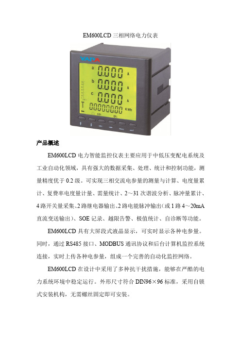
电压测量:额定输入100V/220VAC,最大测量450VAC
4路,无源节点光隔离输入,隔离电压1500VDC。第3、4路可设置
开关量状态采 为脉冲计数
集
内部24V 直流激励
去抖时间:60ms 采集分辨率:≤2ms
继电器
2路,A 型干触点输出,触点容量5A/30VDC 或5A/250VAC
电能脉冲输出 2路,光隔离输出,隔离电压1500VDC
▪电压、电流的2~31次谐波分量
▪正反向总有功、无功最大需量及发 生时间
▪电压、电流的奇次、偶次、总谐波 ▪电参量极值统计及发生时间
畸变率
▪电参量越限告警Βιβλιοθήκη ▪K 因数电能计量
▪三相有功、无功绝对值电度量 ▪48时段4费率
▪正反向总有功、无功电度量
▪四象限无功电度量累计
输入/输出功能
▪开关量输入
▪4~20mA 直流变送输出
电流(Ia/Ib/Ic/In)
0.2级
0~9999A
功率因数(PFa/PFb/PFc/PF∑)
0.5级
0<|COSΦ|<1
有功功率(Pa/Pb/Pc/P∑)
0.5级
0~1260000kW
无功功率(Qa/Qb/Qc/Q∑)
0.5级
0~1260000kvar
视在功率(Sa/Sb/Sc/S∑)
0.5级
0~1260000kVA
EM600LCD 具有大屏段式液晶显示,可实时显示各种电参量。 同时,通过 RS485 接口、MODBUS 通讯协议和后台计算机监控系统 连接,实时上传各种电参量,组成一个完善的自动化监控网络。
EM600LCD 在设计中采用了多种抗干扰措施,能够在严酷的电 力系统环境中稳定运行。外形尺寸符合 DIN96×96 标准,采用自锁 式安装机构,无需螺丝固定即可安装。
EM600LCD操作手册Ver1.2
电力智能监控仪表 © Copyright reserved 操作手册
请首先阅读本手册
© Copyright reserved
目
录
1 1. 简述............................................................................................................................................... ...............................................................................................................................................1 1.1. 1.2. EM600LCD 的功能.............................................................................................................. 1 EM600LCD 的特点.............................................................................................................. 1
�
安装时,应先将 EM600LCD 两边的安装卡松开取下,将 EM600LCD 于面板前方推放入 安装孔内,然后从后方沿装置的沟槽将安装卡安上并使之挤紧面板,此时装置将牢固地 固定在面板上。见图 2-1-3。
图1-1-1 装置外形图
1.2. EM600LCD 的特点
MU96多功能配电仪表使用说明书

MU96多功能配电仪表使用说明书1 序 (4)1.1选型表 (4)1.2使用要点 (4)1.3安全守则 (4)1.4使用条件 (4)2 多功能配电仪表 (5)2.1多功能配电仪表简介 (5)2.2MU96 系列多功能配电仪表的特点 (5)2.3应用领域 (5)2.4多功能配电仪表简介 (6)2.5MU96 系列多功能配电仪表的特点 (6)2.6应用领域 (6)3 功能简述 (7)4 技术规格参数 (7)4.1输入信号 (7)4.2测量精度 (7)4.3通讯 (8)4.4适用环境 (8)4.5安全性 (8)4.6外形尺寸和重量 (8)4.7电源 (8)5 包装 (8)6 安装和接线方法 (9)6.1盘面固定方法 (9)6.2安装尺寸 (9)6.3安装方法 (9)6.4接线方法 (10)7 工程施工注意事项 (13)7.1电压输入 (13)7.2电流输入 (13)7.3安装CT (13)7.4通讯接线 (13)8 用户操作方法 (14)8.1定义及说明 (14)8.2系统上电 (15)8.3察看U/I/PQS (15)8.4察看其他电参数 (16)8.5DI状态指示 (16)8.6DO状态指示 (16)8.7通讯指示 (16)9 系统编程模式 (16)9.1进入/退出系统编程模式 (16)9.2系统编程模式下的操作 (17)9.3DO状态设置和察看 (17)9.4通讯地址设置 (17)9.5通讯波特率设置 (18)9.6PT设置 (18)9.7CT设置 (19)9.8DO模式设置 (19)9.9电度脉冲工作方式设置 (20)9.10继电器工作方式设置 (24)9.11自动循环显示方式设置 (26)9.12密码设置 (27)9.13电度清零 (27)9.14显示版本号及产品序列号 (27)10 通讯及组态操作说明 (28)10.1MODBUS-RTU通讯简介 (28)10.2MU96 系列的应用细节及参量地址表 (35)1序1.1选型表注:另有2S功能为单相电流功能1.2使用要点z本说明书旨在帮助您快速安装、操作和系统集成MU96 系列智能电力仪表。
- 1、下载文档前请自行甄别文档内容的完整性,平台不提供额外的编辑、内容补充、找答案等附加服务。
- 2、"仅部分预览"的文档,不可在线预览部分如存在完整性等问题,可反馈申请退款(可完整预览的文档不适用该条件!)。
- 3、如文档侵犯您的权益,请联系客服反馈,我们会尽快为您处理(人工客服工作时间:9:00-18:30)。
产品简介|Description
多功能电力仪表用于配电系统的连续监视与控制。
可测量双回路三相电流、功率、电能和需量,以及一路母线三相电压。
具备4路数字量输入(DI),1路24V直流辅助电源输出。
所有数据都可以通过RS485通信口用Modbus®-RTU协议读出。
双回路多功能表将精确测量、智能化多功能和简单人机界面结合在一起。
多功能电力仪表,节省盘面空间,占用通信资源少,降低配电监控系统和能源管理系统的造价,用户在实现配电自动化和能源管理的同时节省大量投资。
应用领域|Applications
■能源管理系统
■工业自动化
■小区电力监控
■变电站自动化
■配电网自动化
■智能建筑
雅达电子2015最新款产品图
面板显示
高亮度LED显示
3相测量值直观显示
I/O状态显示
通讯:
MODBUS-RTU通讯协议RS-485接口
其它特征:
96X96小型尺寸
雅达仪表外形尺寸:96*48------开孔尺寸:(91*45)
雅达仪表外形尺寸:48*48------开孔尺寸:(45*45)
雅达仪表外形尺寸:72*72------开孔尺寸:(67*67)
雅达仪表外形尺寸:80*80------开孔尺寸:(76*76)
雅达仪表外形尺寸:96*96------开孔尺寸:(91*91)
雅达仪表外形尺寸:120*120------开孔尺寸:(111*111)
面板安装
安装方法
1).在固定的配电柜上,选择合适的地方开一个开孔尺寸的安装孔。
2).取出仪表,松开定位螺丝,取下固定夹。
3).将仪表安装插入配电柜的仪表孔中。
4).插入仪表的固定夹,固定定位螺丝。
注:L-N为辅助电源请按仪表外壳接线图正确接线!
接线图完整版|Dimensions
辅助电源
多功能电力仪表Acuvim390具备通用的(AC/DC)开关电源输入接口,若不作特殊声明,提供的是220V(AC/DC)或110V(AC/DC)电源接口的标准产品,仪表极限的工作电源电压为AC/DC:80-270V,请保证所提供的电源适用于该系列产品,以上防止损坏产品。
A.采用交流电源建议在火线一侧安装1A的保险丝。
B.对于电力品质较差的地区中,建议在电源回路安装浪涌抑制器防止雷击,以及快速脉冲群抑制器。
输入信号
产品采用了每个测量通道单独采集的计算方式,保证了使用时完全一致、对称,其具有多种接线方式,适用于不同的负载形式。
说明:
A。
电压输入:输入电压应不高于产品的额定输入电压(100V 或400V),否则应考虑使用PT,在电压输入端须安装1A保险丝。
B.电流输入:标准额定输入电流为5A,大于5A的情况应使用外部CT。
如果使用的CT上连有其它仪表,接线应采用串接方式,去除产品的电流输入连线之前,一定要先断开CT一次回路或者短接二次回路。
建议使用接线排,不要直接接CT,以便于拆装。
C。
要确保输入电压、电流相对应,相序一致,方向一致;否则会出现数值和符号错误!!(功率和电能)
D。
仪表输入网络的配置根据系统的CT个数决定,在2个CT的情况下,选择三相三线两元件方式;在3个CT的情况下,选择三相四线三元件方式。
仪表接线、仪表编程中设置的输入网络NET应该同所测量的负载的接线方式一致,不然会导致仪表测量的电压或功率不正确。
其中在三相三线中,电压测量和显示的为线电压;而在三相四线中,电压测量显示的为相电压。
备注:如需更详细资料请与我们联系(江阴市雅达电子有限公司),我们会第一时间为您讲解!。
