安装和操作手册-ClearOne
Clearcase安装配置操作手册
Clearcase安装配置操作手册裸奔的蚂蚁西安软件测评中心二〇〇七年三月1前言1.1工具介绍ClearCase是一种配置管理工具,由Rational公司开发,是开发小组用来跟踪、管理软件开发过程各个工件的配置管理系统, ClearCase可以协助开发组织更好地管理软件开发进程。
ClearCase可以和Rational公司的其他软件紧密结合,例如UCM、ClearQuest等等。
ClearCase包括两套:ClearCase LT和ClearCase (MultiSite)。
前者可以用于在同一个局域网的开发小组,适合于中小型开发组织;ClearCase (MultiSite)则适应于分布于不同地理位置、不同局域网的开发小组,适合于大型的开发组织。
1.2工具特点ClearCase的核心功能是版本控制,它是对软件开发进程中一个文件或一个目录发展过程进行追踪的手段。
在软件开发环境中,ClearCase可以对每一种对象类型(包括源代码、二进制文件、目录内容、可执行文件、文档、测试包、编译器、库文件等)实现版本控制,同时还提供了先进的版本分支和归并功能用于支持并行开发。
*支持广泛的文件类型ClearCase不仅可以对软件组件的版本进行维护和控制,也可以对一个非文本文件、目录的版本进行维护。
用户可以定义自己的元件类型,也可以使用ClearCase中的预定义类型。
在存储时,ClearCase可以利用增量算法将文本文件存储在一个特殊结构的文件容器中,或采用标准的压缩技术控制任何操作系统文件。
(这比以往的存储形式节省了50%-70%的存储空间。
)*在版本树中观察元件发展的过程在ClearCase中,文件版本的组织体现在版本树结构中。
每一个文件都可以通过checkout-edit-checkin的命令形成多个版本,还可以包含多层分支和子分支。
*对目录和子目录进行版本控制ClearCase可以对目录和子目录进行版本控制,允许开发者对其数据的组织发展过程进行追踪。
clearone常用产品技术说明
1…………………………………………………………………… XAP 800专业音频会议系统2…………………………………………………………………… XAP 400专业音频会议系统3……………………………………………………………………………… XAP TH2电话接口4……………………………………………………………………… XAP NET以太网控制接口5 ………………………………………………………………………GT1524单通道回声消除器6……………………………………………………………………… PSR 1212数字矩阵调音台7……………………………………………………………… RAV600/900一体化商务会议系统8………………………………………………………最新专业会议系统 Converge™ 560/590 9………………………………………………………………………… MAX 桌面电话会议终端10………………………………………………………………MAX Wireless无线电话会议终端11………………………………………………………………………… ACCUMIC高性价比麦克XAP 800专业音频会议系统市场上功能最齐全、最成熟的音频会议系统。
XAP 800以其独一无二的音频处理能力,引领了音频会议系统的新标准!产品特点出众的音频性能分布式回声消除——更有效地消除回声噪音抑制——抑制来自风扇或HVAC 系统的背景噪音全双工——使与会者在同一时间不用切入切出就可以互相交流第一麦克优先——通过只激活最靠近说话人的麦克来消除中空“隧道”声8路麦克/线路输入,4 路纯线路输入12 路输出20Hz 到20kHz带宽,提供完整的音频响应自动电平控制和自动增益控制八个独立的音频处理模块,每个都包含有15 段滤波器灵活的配置可扩展-连接多个XAP 设备(XAP 400,XAP800,XAP TH2),提供多达64路麦克输入和16 路电话接入32x32 音频矩阵,每个交叉点具有电平控制功能多种系统控制功能选项:遥控、音量控制、选择控制、第三方控制系统,如AMX、Cresstron 通过G-Ware软件、RS-323端口进行配置控制12 路双向音频线路的增强型扩展总线来连接其他的XAP 产品1U机架式安装简单地操作和控制所有输入、输出、宏和预置的标识都保存在设备里前面板可以实现增益和静音控制在会议进行中可以执行32 个预置选择而不会影响正在进行的操作宏脚本语言和宏记录器简化了宏的创建RAMP 串行命令通过增益调节进行控制,无需外部音量卡会议容量XAP TH2 和XAP400具有电话会议功能连接多达16个XAP TH2获得16 方电话会议的能力技术参数音频性能:条件:除非另外指定,所有的测量都限制在一个22Hz—22KHz 带宽范围内进行(没有额外开销);频率响应:20Hz—20KHz ±1dB;噪音(EIN):-126dB,20KHz BW,最大增益,阻抗=150Ω;总谐波失真:<0.02%;信噪比:80dBre0dBu(A-weighted);动态范围:100dB(A-weighted) ;串音<-91dB re;20dBu@20KHz 通道到通道矩阵混音参数:32x32 矩阵;12 路逻辑输入/输出;12 路扩展线路输入/输出;8路可指定的音频处理模块输入/输出自动混音器参数:打开麦克风数量(NOM);PA适应模式;第一麦克优先模式;最后麦克模式;最大麦克数量模式;环境电平;选通率;衰减量;保持时间;收敛率可指定的处理模块:滤波器:全通、低通、高通、低曲柄型响应、高曲柄型响应、参量均衡、梳形滤波、CD Horn;旁通: Bessel 、Butterworth 、Linkwitz-Riely;压缩器;延迟可调节至500ms麦克输入配置:输入增益调节;麦克或线路电平;幻象电源开/关;回声消除开/关;噪音抑制开/关;滤波器:全通、低通、高通、梳形滤波、参量均衡;静音开/关;主席优先开/关;自动增益控制(AGC)开/关;语音平衡器开/关;自动gate/手工gate;自适应环境电平开/关麦克/线路输入1—8:桥接平衡按压式接线排;阻抗:5 KΩ;正常电平:可调整-55dBu,-25dBu,0dBu;最大电平:-35dBu,-5dBu,+20dBu;回声消除:130ms 尾音时间(房间增益12dB);噪音抑制:衰减6—15dB;幻象电源;24V,可选择线路输入9—12:桥接平衡按压式接线排;阻抗:>10 KΩ;正常电平:0dBu;最大电平:20dBu输出1—12:平衡按压式接线排;阻抗:50Ω;正常电平:0dBu ;最大电平:20dBu 扩展总线输入/输出:专有网络,RJ-45(2)接口, 115.2kbps ,110K;五类双绞线,任何两个XAP800、XAP400或PSR1212之间连接最长可达24 米RS-232串口:DB-9 接口(母头),波特率9600/19200/38400(缺省)/57600;8 位数据位,1 位停止位,无奇偶校验位,硬件流量控制开(缺省)/关控制/状态:DB-25 接口(母头)A/B(2);输入A/B:activelow(接地);输出A/B:open collector,最大40VDC,每个40mA;+5VDC 管脚(300mA过流保护)远程面板A/B:4 管脚按压式接线排;RS-485 专用协议;五类双绞线,一对数据,一对电源和地;+15VDC(300mA过流保护)认证:FCC,CSA,IC,CE,NOM,ACA,SABS,JATE体积(长x宽x 高):43.8x26x4.5厘米重量:净重3.2公斤,装箱5.5公斤设置软件:G-WareXAP 400专业音频会议系统成熟、专业的音频会议系统,包含了最完善的音频技术。
clearcom内通系统配置操作手册V
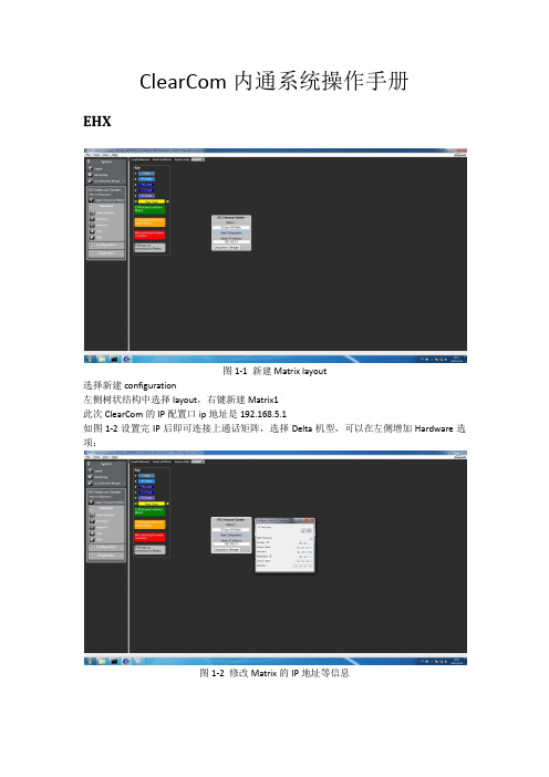
ClearCom内通系统操作手册EHX图1-1 新建Matrix layout选择新建configuration左侧树状结构中选择layout,右键新建Matrix1此次ClearCom的IP配置口ip地址是192.168.5.1如图1-2设置完IP后即可连接上通话矩阵,选择Delta机型,可以在左侧增加Hardware选项;图1-2 修改Matrix的IP地址等信息图1-3 右键选择Discovery Hardware如图1-3右键选择configuration -> create new configuration -> discovery hardware自动查找矩阵上的硬件;也可以指派Empty,进入Hardware的Cards and Panels手动添加对应槽位的硬件;图1-4 management可选择导入导出配置文件图1-4是configuration的保存和导入导出;还可以通过file -> user management 进行配置工程文件的导入导出,如图1-5所示;此处的Configuration是对应Project的矩阵设置数据表,每个通话矩阵可以有多个configuration,但是每次只能加载对应的一个configuration;图1-5 导入导出对应的配置文件和工程文件图1-6 查看card and panelsGo Online(No Merge)上线但不将当前配置设置到矩阵中;Go Online(EHX To System)合并当前EHX配置到矩阵;Go Online(System To EHX)将矩阵的配置下载到EHX;Go Online(Virual Merge)虚拟合并配置,并在有冲突时给予配置的优先级;此次我们一共配置了三块板卡,分别为MVX-A16、E-QUE FSⅡ和IVC-32Card slot第一块卡选择MVX-A16,这块模拟端口卡用于控制连接在卡上的面板和接口,通过5类网线发送平衡音频和422信号;我们在这块卡上设置了摄像机通话混音器MDIF1001、主持人返听UHF IFB TRANSmitter和演播室的PGM信号;在第三卡槽设置了E-Que FSⅡ用于FreeSpeak无线腰包供现场导演使用,具体配置如下所示在第四卡槽位置设置了IVC-32板卡,用于通过网络连接的各个导控和总控使用的通话面板,具体配置名称如图1-9,由于是网络接口,需要配置网络IP通讯口192.168.5.3,子网掩码255.255.255.0,默认网关192.168.5.254图1-7 E-Que FS Ⅱ板卡图1-8 设置天线的长度补偿如图1-8所示,右侧的页签Cable length Compensation根据天线与通话矩阵的位置设置对应的距离,系统可以提高对应端口的增益弥补信号的衰减;图1-9 设置IVC-32板卡的IP地址图1-10 设置板卡对应的User ID上图中User ID设置为bc1,Network设置LAN,Audio Codec设置G722;如遇面板坏了,可以直接通过设置IP地址(面板上不要插网线进行设置IP等参数,包括User ID等),设置完成后插上网线等待重启连接通话矩阵;图1-11 完成配置全部设置完成后,需要将配置写进通话矩阵内,点击Apply Change to Matrix跳出如图1-11的对话框,点击OK,等待矩阵完成配置;如何设置腰包图2-1 打开腰包的注册通道一个新的无线腰包该如何设置呢?1)首先给无线腰包装好电池2)安装好演播室用FS天线,在有效范围内使腰包可以通过天线接收到信号3)打开软件点击打开Enable Registration Mode,然后打开腰包电源选择对应系统PIN码,选择configuration内通名字如OCJ INTERCOM Configuration后,腰包就可以进入内通系统;4)点击软件上的Fetch Registed Beltpacks From Matrix添加系统认到的腰包ID等信息图2-2 设置腰包的通道和通话模式设置无线腰包的快捷标签,左侧页签选择Panels,上方的下拉页签选择到FD-A1 FreeSpeak 无线腰包,下方是矩阵Panels、Interfaces、Fixed Groups等音频源;将需要与无线腰包联系的TD、PD、VE、FD-A2拖拽上腰包的空档处,右键设置为Talk and Listen如何设置无线腰包角色图3-1 设置无线腰包的角色信息此次内通系统规划了ABCD四个演播室区域和总控系统工程师共5个无线腰包的角色;但由于需要考虑主备腰包同时使用等功能,因此设置了FD-A1/FD-A2、FD-B1/FD-B2、FD-C1/FD-C2、FD-D1/FD-D2、sys1/sys2共5个组;该页签下的右侧,可以设置无线腰包的输入输出增益、耳麦的侧音电平、电量报警、报警方式等设置(所有设置可以在腰包上长按manu进入菜单设置);图3-2 设置无线腰包的模式为No Default如图3-2所示,请选择No Default,其作用是每次打开腰包时能够选择想要的Beltpacks Roles,这样每个腰包之间都是可以互为备份的,而一旦一个腰包选择了一个角色后,其他腰包就无法再选择该角色,这就是角色唯一性;图3-3 Fixed Groups如图3-3所示,在左侧页签内选择Fixed Groups,添加对应的5组,每组添加2个无线腰包,分别设置了Talk and Listen,且组内的两个腰包也都设置了相互的标签可以直接通话,方便使用;通话面板的设置图4-1 选择对应的演播室面板一台新的通话面板如何接入系统中呢?1)通话面板接上电源,并插上网线;2)面板上manu进入菜单,再按面板右侧info,选择net config,设置对应的IP地址、子网掩码和默认网关;3)设置面板上的User ID和password;(需要选择已经在软件中设置的user id,且唯一);4)重启面板后就可以读取User ID对应的面板配置和PAGE信息;图4-2 选择对应的Panels、Interface、Fixed Groups等信号源图4-3 设置个性化的Page如图4-2所示,选择对应的面板类型信息,再选择对应的PAGE页数,即可设置对应的页面格局,其中面板上绿色的框是听,红色的框是说;在Panels页面上可以对面板的格局等信息配置进行保存和导入导出,还可以设置Audio Mixer 定义每块面板对矩阵输出进行配置输出节点,Identify panel可以点亮目标面板;如何设置无线腰包天线图5-1 pin码将无线腰包天线的通讯线接在E-Que FS板卡的后背板上,然后按照图5-1上的设置PIN码为0000,这样可以在无线腰包里输入PIN码,进入选择系统界面,可以将无线腰包加入到内通系统;图5-2 查看天线的状态灯图5-2上我们需要关注的是一个绿灯一个黄灯,绿灯代表电源,黄灯代表信号传输。
TrueClean 空气消除器安装 操作 维护说明书

TrueClean® Air EliminatorTABLE OF CONTENTSIntroduction . . . . . . . . . . . . . . . . . . . . . . . . . . . . . . . . . . . . . . . . . . . . . . . . . . . . . . . . . . . . . . . . . . . . . . . . . . . . . . . . . . . . . .3 Safety . . . . . . . . . . . . . . . . . . . . . . . . . . . . . . . . . . . . . . . . . . . . . . . . . . . . . . . . . . . . . . . . . . . . . . . . . . . . . . . . . . . . . . . . . . . .4 At a Glance . . . . . . . . . . . . . . . . . . . . . . . . . . . . . . . . . . . . . . . . . . . . . . . . . . . . . . . . . . . . . . . . . . . . . . . . . . . . . . . . . . . . . . .5 Installation . . . . . . . . . . . . . . . . . . . . . . . . . . . . . . . . . . . . . . . . . . . . . . . . . . . . . . . . . . . . . . . . . . . . . . . . . . . . . . . . . . . . . . .6 Process of Operation . . . . . . . . . . . . . . . . . . . . . . . . . . . . . . . . . . . . . . . . . . . . . . . . . . . . . . . . . . . . . . . . . . . . . . . . . . . . .7 Maintenance . . . . . . . . . . . . . . . . . . . . . . . . . . . . . . . . . . . . . . . . . . . . . . . . . . . . . . . . . . . . . . . . . . . . . . . . . . . . . . . . . . . . .8 Cleaning . . . . . . . . . . . . . . . . . . . . . . . . . . . . . . . . . . . . . . . . . . . . . . . . . . . . . . . . . . . . . . . . . . . . . . . . . . . . . . . . . . . . . . . . . .9 Chemical Compatibility . . . . . . . . . . . . . . . . . . . . . . . . . . . . . . . . . . . . . . . . . . . . . . . . . . . . . . . . . . . . . . . . . . . . . . . . . .9 Spare Parts . . . . . . . . . . . . . . . . . . . . . . . . . . . . . . . . . . . . . . . . . . . . . . . . . . . . . . . . . . . . . . . . . . . . . . . . . . . . . . . . . . . . . . .9 Warranty . . . . . . . . . . . . . . . . . . . . . . . . . . . . . . . . . . . . . . . . . . . . . . . . . . . . . . . . . . . . . . . . . . . . . . . . . . . . . . . . . . . . . . . .10 Notes . . . . . . . . . . . . . . . . . . . . . . . . . . . . . . . . . . . . . . . . . . . . . . . . . . . . . . . . . . . . . . . . . . . . . . . . . . . . . . . . . . . . . . . . . . . . .11IntroductionABOUTThank you for purchasing a TrueClean® product.This manual covers the TrueClean Air Eliminator .The Air Eliminator is designed for minimal routine maintenance, but care and attention should be given to the instructions provided in this manualDo not remove any labeling on any TrueClean product .Immediately replace any label that is missing .SafetyIMPORTANT SAFETY INFORMATIONRead this manual before installing, operating, and maintaining this equipment .Failure to read the manual can result in personal injury and/or equipment damage .Do not attempt to remove and/or modify any TrueClean products or programming .Doing so can create unsafe conditions for the operator(s) and/or surrounding persons .Any change to TrueClean products or programming will void any and all warranties .Do not place any TrueClean product in an application where general product service ratings are exceeded .Doing so puts the operator(s) and/or surrounding persons at risk of personal injury and/ or result in equipment damage .If, at any point during operation a Danger, Warning, or Caution indication is present, the operator should immediately take steps to resolve the problem and/or seek assistance from a supervisor . Do not remove any labeling on any TrueClean product .Immediately replace any label that is missing .DISCLAIMER OF LIABILITYTrueClean does not assume responsibility and expressly disclaims liability for loss, damage, or expenses that arise in any way from the installation, operation, use, or maintenance performed in accordance with this manual .TrueClean assumes no responsibility for any infringement of patents or other rights of third parties that may result from use of the module .No license is granted by implication or otherwise under any patent or patent rights .TrueClean reserves the right to make changes to the product, specifications, or this manual without prior notice .CONNECTION1" TUBE CONNECTION 1" Tube Connection GOOSENECK CONNECTION2-7/1Connection TRI-CLAMP ® CONNECTIONAt a GlanceAIR ELIMINATOR PARTS LISTITEM NUMBER CONFIGURATION 1InstallationTECHNICAL DATA:Maximum pressure: 145 psigMaximum temperature: 194°FBall material: PolypropyleneBall Density: 0.033 lbs/in3INSTALLATION:CAUTION: Prior to installation, verify that the piping system is not pressurized and that it has been adequately drained . For proper function of the TrueClean Air Eliminator, the following items should be observed:1 .Verification of the product density is greater than theball density listed in the technical data .2 .Vertical installation of the TrueClean Air Eliminatorvalve assembly .3 .Use a Tri-Clamp clamp and gasket to attach theTrueClean valve to the piping system .Note: It is advised to use a short outlet tee for installation . Although this valve is designed to be Cleaned Out-Of-Place (COP), the tee should be short to ensure proper cleaning during Clean-In-Place (CIP) of the pipeline.Process of OperationAPPLICATION:The Air Eliminator is a sanitary air relief valve . It allows air out while also preventing product from leaking out. The Air Eliminator may be utilized in various manners, specifically:High point vent: Installed vertically on the top of a pipeline or container . This application can be used to bleed a pipeline of air pockets that have formed on account of new piping installation or other means of air entrainment in the process .Check valve: This occurs when product flows into the valve body, moving the polypropylene ball upwards to form a tight seal with the O-ring .Air Eliminator: To act as an air eliminator, the valve is installed ahead of a pump on top of the inlet pipe . This prohibits the pump from drawing a vacuum because of the spontaneous release of air on the suction side of the pump which prevents cavitation caused by air bubbles that would otherwise be drawn in by the pump .WORKING PRINCIPLE:The Air Eliminator is composed of a vent top clamped to a vent bottom with a freely moving polypropylene ball . The ball seals on the bottom or top seat dependent on process conditions .In Figure A , the ball raises from the lower seat as air burps from the process line .In Figure B , the ball, which is lighter than water, closes against the upper seal when encountering product . This seals product from escaping the vent . Once product pressure is not present, the ball resets to the lower position and seals against the lower o-ring, preventing air from enteringthe system .Tri-Clamp ConnectionTri-Clamp ConnectionTri-Clamp ConnectionO-ring seal preventsfluid leakageFIGURE AFIGURE BO-ring seal preventsfluid leakageMaintenanceWARNING: Prior to any maintenance, depressurize and drain the piping system.1. Disconnect the TrueClean Air Eliminator from the piping system .To do this remove theprocess line clamp by turning the line clamp wingnut counterclockwise, and removethe gasket connecting the Air Eliminator to the process tubing .2. Use a 1” cap and clean gasket to close the process.3. Before disassembling, visually check the valve for any corrosion or damage .4. Disassemble the Air Eliminator by removing the valve body clamp .Turn the body clampwingnut counterclockwise until the clamp can be removed .Then remove the clampand gasket .5. Inspect the valve surfaces for damage .If there is damage to the surface, polishing orreplacement may be required depending on the severity of damage .If in doubt, contact your TrueClean distributor for assistance .6. Remove the O-rings from the groove in the vent top and bottomCAUTION: An O-ring pick tool is necessary to safely remove the O-ring without causing damage to the O-ring or the vent top .Failure to do this may void the warranty .7. Inspect the gasket, O-rings and ball .Replace them if there are any signs of damage .8. Complete a final inspection, looking for corrosion or damage within the device.9. Apply a food-grade FDA approved lubricant to the O-rings and install it in the proper O-ringgroove inside the vent top and bottom using the O-ring pick tool to assist with install .10. Reassemble the Air Eliminator .11. Ensure the process is not operating and the area is safe .Remove the cap installed earlierfrom the process line .12. Install the Air Eliminator and line clamp back into the piping system .CleaningThe TrueClean Air Eliminator is designed for COP cleaning only. Therefore, follow all steps outlined in the maintenance section above, paying special attention to the warning and caution .Whilethe valve is disassembled, standard operation procedures at the respective facilities should be followed to clean the valve .Chemical CompatibilityTo verify Air Eliminator will work with your specific application, reference our Chemical Compatibility Chart at /uploads/resources/Chemical-Compatibility-Chart.pdfto help in the selection of elastomers .Spare Parts ListO-RINGS• Viton part number: FDA-118-SFY• EPDM part number: FDA-118-EGASKETS• Viton part number: 40MP-SFY-2• EPDM part number: 40MPE-2BALL• Polypropylene part number: 88117019WarrantyA .GENERAL PROVISIONS: Central States Industrial Equipment & Service Inc. (the “Company”) warrants exclusively tothe original purchaser (the “Customer”) that equipment or parts thereof manufactured and sold by the Company will be free from defects in material and workmanship only, under normal use and service, for a period of one (1) year from the original shipment date. The Company shall not be liable for any loss of revenue or profit, loss by reason of plant shutdown, non-operation or increased cost of operation, loss of products or materials, or other special or consequential loss or damages resulting from any such warranted defects .This warranty will not apply to any equipment or parts which has been subjected to accident, alteration, abuse, or misuse .This warranty is in lieu of all other warranties .All other warranties, both express or implied (including, but not limited to, the implied warranties of merchantability and fitness for a particular purpose) warranties are hereby excluded and waived. The Company’s only obligation and liability shall be to fulfill the warranty specifically stated herein. The Company will neither assume nor authorize any other person to assume for it any other obligation or liability in connection with the equipment or parts .In the event of a claim under this warranty, the Company’s sole and exclusive liability for any warranted equipment or parts shall be, at the Company’s option, limited to the following (a) the purchase price of the equipment or parts that are defective, (b) replacement of the defective equipment or parts or (c) repair of the defective equipment or parts .B .RETURN OF PARTS OR EQUIPMENT TO COMPANY PLANT: In the event the Company elects to inspect the allegeddefective equipment or parts for possible repair, Company will notify Customer in writing, and the equipment or parts must be returned with transportation cost prepaid by the Customer .In the event the Company’s inspection confirms defective equipment or parts covered by this warranty, the Company shall have the option to select any of the remedies described in Section A above. No transportation for returned or replaced items will be paid by the Company unless written approval for transportation charges is given by the Company .C .COMPONENTS NOT MANUFACTURED BY THE COMPANY: Components not manufactured by the Company, butfurnished as part of its equipment (for example: valves, controls, gauges, electrical switches or instruments, etc .) will be warranted by the Company only to the extent of the component manufacturer’s warranty .D .REPAIR OF EQUIPMENT INSTALLED IN THE CONTINENTAL UNITED STATES: In the event the Company electsto repair a covered item and it is, in the judgement of the Company, impractical to return the equipment or parts for repairs, the Company may arrange for the repairs to be made by its personnel or, at its option, sublet such repairs to a qualified company. The Customer will be expected to cooperate by making the equipment or parts available and accessible when the work is scheduled and is expected to provide the necessary utilities .If local labor conditions prohibit such work being done by Company personnel under the conditions and at the rates payable by its contracts with its employees, the Company obligation shall be limited to supervision of the work, replacement of defective parts, and labor costs in an amount equal to the amount which would be payable fora reasonable number of hours required to make the repairs at the rates payable under the terms of Companycontracts with its employees .In such event, all labor costs shall be paid by the Customer and the Company will reimburse the Customer to the extent set forth above .E .REPAIR OF EQUIPMENT INSTALLED OUTSIDE THE CONTINENTAL UNITED STATES: In the event the Companyelects to repair a covered item for a Customer located outside the continental United States and it is, in the judgement of the Company, impractical to return the equipment for repairs, the Company shall have the additional options (in addition to the other options described herein) of either sending a service representative to repair (or supervise the repairs) or paying Customer a reasonable amount to allow the Customer to have the repairs made locally; provided, that in such situation, Company shall have no obligation to repair or replace equipment or parts that are repaired on by third party contractors selected by Customer .Notes11TC AIR ELIMINATOR IOM—REV 08/20。
安装和清洁维护操作手册说明书

WARNINGREAD AND SAVE THESE INSTRUCTIONS Installer: Leave this manual with the homeowner.CAUTIONCLEANING & MAINTENANCEOPERATIONFor quiet and efficient operation, long life, and attractive appearance - lower or remove grille and vacuum interior of unit with the dusting brush attachment.The motor is permanently lubricated and never needs oiling. If the motor bearings are making excessive or unusual noises, replace the motor with the exact service motor. The impeller should also be replaced.SE80TL SE110L SE150La). Use this unit only in the manner intended by the manufacturer. If you have questions, contact the manufacturer.b). Before servicing or cleaning unit, switch power off at service panel and lock the service disconnecting means to prevent power from being switching on accidentally. When the service disconnecting means cannot be locked, securely fasten a prominent warning device, such as a tag, to the service panel.c). Installation work and electrical wiring must be done by a qualified person(s) in accordance with all applicable codes and standards, including fire-rated construction codes and standards.d). Sufficient air is needed for proper combustion and exhausting of gases through the flue (chimney) of fuel burning equip- ment to prevent backdrafting. Follow the heating equipment manufacturer’s guideline and safety standards such as those published by the National Fire Protection Association (NFPA), and the American Society for Heating, Refrigeration and Air Conditioning Engineers (ASHRAE), and the local code authorities.e). When cutting or drilling into wall or ceiling, do not damage electrical wiring and other hidden utilities. f ). Ducted fans must always be vented to the outdoors.g). Acceptable for use over a tub or shower when connected to a GFCI (Ground Fault Circuit Interrupter) - protected branch circuit (ceiling installation only). h).This unit must be grounded. i). Not for Use in Kitchens.j). To reduce risk of fire and to properly exhaust air, be sure to duct air outside – Do not vent exhaust air into spaces within walls or ceilings or into attics, crawl spaces, or garages.k).WARNING: To Reduce The Risk Of Fire Or Electric Shock, Do Not Use This Fan With Any Solid-State Speed Control Device.l). The fan must not be installed in a ceiling thermally insulated to a value greater R40.1.For general ventilating use only. Do not use to exhaust hazardous or explosive materials and vapors.2.This product is designed for installation in ceilings up to a 12/12 pitch (45 degree angle). Duct connector must point up.DO NOT MOUNT THIS PRODUCT IN A WALL.3.To avoid motor bearing damage and noisy and/or unbalanced impellers, keep drywall spray, construction dust, etc. off power unit.4.Please read specification label on product for further information and requirements.*The manual in electronic format can be download in our company web, or obtained from our dealer.WARNING -TO REDUCE THE RISK OF FIRE, ELECTRIC SHOCK, OR INJURY TO PERSONS, OBSERVE THE FOLLOWING:The fan, light, and night light can be operated separately. Use a 3-function wall control. See “Connect Wiring” for details.Hold the housing so that it is in contact with the bottom of the joist. Attach the housing with four (4) screws to the joist through the holes in each mounting flange.1. MOUNT HOUSING TO JOIST OR I-JOIST.HANGER BAR2. MOUNT WITH HANGER BARS2a. Sliding hanger bars have been provided, which allow the housing to be positioned accurately anywhere between the framing. The bars span up to 24 in. and can be used on all types offraming: I-joist, standard joist, and truss construction. Slide hanger bars onto housing and adjust as needed to fit between framing.2b. Extend the hanger bars to the width of the framing. Position the ventilator with the hanger bar tabs wrapped around the bottom edge of the framing, holding the ventilator in place.Secure hanger bars to framing using one screw on each end of hanger bar.Select a proper hole and secure the hanger bars together using flange screws.3. ATTACH DAMPER/DUCT CONNECTORSnap the damper/duct connector onto the fan housing. The connector must be flush with the top of the housing, and the damper flap should fall closed.Insulated flexible duct is recommended for the quietest possible installation. If rigid duct is used, a short (1-3 feet) section of insulated flexible duct will ensure quiet operation.TYPES OF TYPICAL INSTALLATIONS1. Do not use in a cooking area.2. Two ways to connect ductwork to a factory-shipped unit.ASSEMBLY INSTRUCTIONS1. Housing mounted to I-joists (Start at “ASSEMBLY INSTRUCTIONS 1”)2. Housing mounted to joists (Start at “ASSEMBLY INSTRUCTIONS 1” )3. Housing mounted to truss (Start at step “ASSEMBLY INSTRUCTIONS 2”)PLAN THE INSTALLATION4. INSTALL ROUND DUCTWORKConnect the round ductwork (not included) to the damper/duct connector, and run the ductwork to a roof or wall cap (not included). Using tape (not included), secure all the ductwork connections so that they are air tight.ASSEMBLY INSTRUCTIONSCONNECT ELECTRICAL WIRINGINSTALL GRILLERun 120 V AC house wiring to the location of the fan. Use only UL-approved connectors (not included) to attach the house wiring to the wiring plate. Refer to the wiring diagram, and connect the wires as shown.The ducting from this fan to the outside of building has a strong effect on the air flow, noise and energy use of the fan. Use the shortest, straightest duct routing possible for best performance, and avoid installing the fan with smaller ducts than recommended. Insulation around the ducts can reduce energy loss and inhibit mold growth. Fans installed with existing ducts may not achieve their rated air flow.Insert the light plug from the grille assembly into the wire panel.Pinch the grille springs on the sides of the grille, and position the grille into the housing with the grille springs in the appropriate slots. Push the grille assembly towards the ceiling to secure.Remove the lensCarefully pry out the light lens by inserting a small,flathead screwdriver between the grille and lens.Install the light bulbsInstall a 26W max. fluorescent bulb and a 4W incandescent night light bulb. Replace the lens.This warranty covers all defects in workmanship or materials for:The mechanical and electrical parts contained in this product, for a period of 12 months, from the date of purchase. You must keep and be able to provide your original sales receipt as proof of the date of purchase. This warranty is covered the original retail purchaser of this product. The manufacturer will repair or replace, in your home, any mechanical or electrical part which proves defective in normal household use for a period of 12 months.THIS WARRANTY DOES NOT COVER:• Damages from improper installation • Damages from shipping• Damages from misuse, abuse, accident, alteration, lack of proper care and maintenance • Damages from service by persons other than an authorized dealer or service center.• Labor, service, transportation and shipping charges for the removal of defective parts and for installation of a replacement part, beyond the initial 12-month period.This warranty does not extend to fluorescent lamp starters and tubes.THIS LIMITED WARRANTY IS GIVEN IN LIEU OF ALL OTHER WARRANTIES, EXPRESSED OR IMPLIED,INCLUDING THE WARRANTIES OF MERCHANTABILITY AND FITNESS FOR A PARTICULAR PURPOSE.The remedy provided in this warranty is exclusive and is granted in lieu of all other remedies. This warranty does not cover incidental or consequential damages. Some states do not allow the exclusion of incidental or consequential damages, so this limitation may not apply to you. Some states do not allow limitations on how long an implied warranty lasts, so this limitation may not apply to you. This warranty gives you specific legal rights, and you may also have other rights, which vary from state to state.WARRANTYSERVICE PARTS45d e a3bc 68799PARTPART NAMEQty.1234567891011a b c d eHousingDamper / Duct Connector Wiring plate Screw Blower WheelWire Panel / Harness Assembly Motor1211111141144141Isolator Motor Plate Washer Nut, Hex Lock Grille Assembly (includes part 2&11)Grille Spring Hanger Bar KitScrew* Blower Assembly includes part 5, 4, d, 3, c, b, a. Replacement installation:Remove the screw (part c), then take out the motor plate (part 3) from the housing (part 8) by pushing down the rib in the plate while pulling out on the side of the housing. Replace the broken parts.WARNING: Ensure that the fan is switched off from the supply mains before replacing.Lens。
clearone

SW9000iis 网络集线器
6个网络端口◆DSP处理能力为200MIPS, 有9088iis所有的数字信号处理对象◆宽 范围电源设计◆前后面板均有标准RS232接口供PC接入◆用于GPI硬件接口的 模拟控制端口◆可以储存最多60个DSP 系统设置
BSS代理还是天创 BSS的调试软件看出BSS功能不够水平和 BIAMP和CLEARONE有差距。(如果效果 好天创也不会代理新的音频处理器了) 天创也不是代理BSS全系统的产品 BSS的Soundweb London系列天创没有 代理
卡的名称 MY8-AT MY8-TD MY8-AE
功能 ADAT TDIF-1 AES/EBU
输入 8 8 8
输出 8 8 8
可使用卡的数量 DME64N 4 4 4 DME24N 1 1 1
MY4-AD
MY8-AD MY4-DA MY8-AD24 MY8-AD96 MY8-DA96 MY8-AE96S MY8-AE96 MY16-AT MY16-AE MY16-TD
Converge Pro 880TA
Converge Pro 880TA和Converge Pro 880T的区别 Converge Pro 880TA输出后四个通道改 为功放输出,可以接吸顶音箱,每通道 为35W。这四个通道有反馈抑制功能。
Converge Pro SR1212A
Converge Pro SR1212A和Converge Pro SR1212的区别 Converge Pro SR1212A输出后四个通道 改为功放输出,可以接吸顶音箱,每通 道为35W。这四个通道有反馈抑制功能。
Clear-Com LQ系列产品快速安装指南说明书

The followingQuick Start Guide provides basic installation and configuration instructions for your LQ system. LQ is a new IP interface for Clear-Com audio products. It offers Internet, LAN and WAN connectivity for multi-linking audio.•LQ-2W2 provides connection for two 2-wire analog partyline ports (XLR connectors) •LQ-4W2 provides connection for two 4-wire ports (RJ45 etherCON connectors) •LQ-R2W4 provides connection for four 2-wire ports (XLR) each with a male and a female connector •LQ-R4W8 provides connection for eight 4-wire ports (RJ45, etherCON) • LQ-R2W4-4W4 provides connection for four 2-wire ports (XLR) and four 4-wire ports (RJ45, etherCON).Powering and connecting the LQ units1)Connect the LQ unit to a network using standard Ethernet cable and power it on (use either the DC power supply cable provided or PoE). The 1 rack unit has redundant power supplies. 2) Connect the audio cables. 3)Open a Web browser on a device connected to the same network as the LQ device. 4)Input the IP address shown on the LQ device’s display into the address field of the browser. 5) Enter the default login credentials for the Core Configuration Manager: Username – admin , Password – admin . Core Configuration Manager (CCM)The CCM has three main pages:• Home - Settings for the host device (the device whose IP address the browser is connected to).• Overview - Settings for all devices in a Link-Group.• Assignments – Configuration of audio and data routes between LQ devices. Note: If your network does not support DHCP you must assign a static IP address to the LQ device: 1) Connect a standard (straight) Ethernet cable from a computer to either LAN port on the device. 2) Ensure the computer is in DHCP mode. 3) Open a web browser and input the device’s IP address in the address field. 4) Navigate to the device’s network screen within the home page and allocate a static IP address. LQ™ LQ™ Series Quick Start GuideQuick Start Guide | LQ™ SeriesLinking the devicesEach device’s role is set as Link-Master by default.1)Select one device in the group to be designated as the Link-Master, connect it to the network and power it on. 2)Connect another LQ device to the same network and power it on. 3) Enter the IP address shown on the display of the Link-Member device into the address field of your Web browser to connect to that device’s Core Configuration Manager.Audio port settingsFrom the Core Configuration Manager (CCM) go to Overview > select device > A/B . The LQ devices arrive with the following default settings: 2W Power Disabled Mode Clear-Com Input/Output gain 0dB Network Quality High VOX mode Disabled Termination Disabled 4W Input/Output gain0dB Network Quality High VOX mode Disabled Port FunctionTo Matrix Baud rate 19200 (Eclipse)Note: When connecting any 2-wire device to an LQ Series port, please auto-null each port.Connecting and configuring audio channels Once an LQ device is connected to a Link-Master, click on the Assignments button within the navigation bar to configure channel connections. See the LQ Series System User Guide on the Clear-Com website for more information. Copyright © 2015 HME Clear-Com Ltd. All rights reserved. 4) 5) 6) Navigate to Home > Linking.Click Enter IP address of Link-Master. Click on blue check mark or press <ENTER> key to submit.Select an available device ID (highlighted in blue).7)Click Apply changes.Repeat linking process for each device.8)9)。
UnitClien统一客户端使用说明书V
XX市微度数字统一客户端使用说明书XX市微度数字技术XX(技术部)SHENZHEN MICRODO DIGITAL TECHNOLOGY CO.,LTD2009.05目录第1章.简介21.1欢迎使用统一客户端21.2系统要求21.3系统功能模块31.4软件优点3第2章.客户端的安装与卸载32.1客户端的安装32.2客户端的卸载8第3章.客户端操作指南113.1登录系统113.2设备的添加113.2.1 新建设备组123.2.2 修改设备组名123.2.3 手动增加设备123.2.4 自动搜索设备133.2.5 自动增加设备143.3视频浏览143.3.1 视频连接、播放143.3.2 视频窗口位置的对调153.3.3 视频浏览窗口缩放153.3.4 视频流选择153.3.5 视频播放停止153.3.6 实时拍照163.3.7 反向音频163.3.8 开启音频163.3.9 音量调节163.3.10 分窗显示163.3.11 告警实时视频163.3.12 云台控制163.4录像回放173.4.1 设备的选择173.4.2 本地录像搜索173.4.3 前端录像搜索173.4.4 查看文件173.4.5 播放录像文件173.4.6 删除录像文件173.5告警信息173.5.1 设备的选择173.5.2 告警信息检索183.5.3 查看告警信息183.6录像设置183.6.1 策略配置18录像参数配置183.7告警联动193.7.1 设备的选择193.7.2 告警联动参数设置193.8用户信息203.8.1 用户组新增、修改、删除20 3.8.2 角色的添加、修改、删除20 3.9远程配置213.9.1 设备的选择213.9.2 远程配置213.10远程维护22设备的选择223.10.2 系统升级223.10.3 配置上传、下载223.10.4 其它维护操作223.10.5 SD卡管理233.11日志查询233.11.1 用户日志查询233.11.2 远程日志查询233.12帮助信息23第1章.简介微度数字视频统一客户端(Unit Client)是集视频监控、管理、控制的统一客户端,为您提供便捷的视频监控享受。
丛文录音服务器安装操作手册说明书
丛文录音服务器安装操作手册2016年1月版权说明本手册版权归深圳市丛文安全电子有限公司所有。
保留一切版权。
除了版权法允许的使用方法之外,未经事先许可,任何人不得复制、改编或翻译。
保证说明本手册所含之内容如有改变,恕不另行通知。
深圳市丛文安全电子有限公司对由于本手册的错误而引起的损害不承担责任,对由于提供或使用本手册而随带发生的损害亦不承担责任。
商标说明丛文®是深圳市丛文安全电子有限公司的注册商标。
CONWIN®是深圳市丛文安全电子有限公司的注册商标。
简介目录第1章系统功能概述 (2)1.1简介 (2)1.2功能特点 (2)1.3产品型号 (2)1.4系统结构及流程图 (2)1.5录音服务器安装流程图 (3)第2章安装录音服务器 (4)2.1安装环境 (4)硬件环境 (4)软件环境 (4)2.2硬件板卡安装 (4)硬件安装 (4)录音服务器2线/4线板卡接线方法 (4)录音服务器8线板卡接线方法 (8)2.3软件安装 (10)2.4卸载 (15)第3章录音服务器应用 (16)3.1系统功能 (16)系统设置 (16)录音设置 (16)查看语音卡安装及录音情况 (19)系统登陆与注销 (20)登陆密码管理 (21)3.2查看信息资料 (21)录音记录管理 (21)站点信息 (22)查看系统错误信息 (23)第4章报警中心启用录音服务器设置 (24)4.1启用录音服务器 (24)4.2录音并关联警情 (24)自动拨打电话关联警情 (24)手动关联相关警情 (26)查看相关的报警 (27)导出录音文件 (27)播放录音文件 (27)第5章售后服务 (29)第6章加密锁安装及升级方法 (30)简介第1章 系统功能概述1.1 简介录音服务器应用于接警中心领域,通过联网报警中心软件拨打用户电话,减少手动拨打出现的出错几率并与用户确警的电话进行全程录音,同时录音文件会与当时发生的警情自动相互关联,以备日后在查看警情的同时播放录音文件,为报警中心与公安机关留下关键有力的证据。
clearone SR1212操作手册
一、控制软件安装:1、自动运行设备随带的安装光盘,出现图1所示画面:图12、点击左侧最上面一栏“Converge Console Software”,出现图2所示画面:图23、系统提示需安装支持组件,点击“Install”后系统开始自动安装,直至最后一步,点“Finish”完成安装,然后出现图3所示画面:图三4、点击“YES”出现图4所示画面:图45、点击“Install”后开始自动安装,直至最后一步,点“Finish”完成安装。
6、支持组件安装完毕后,重新点击图1中左侧最上面一栏“Converge Console Software”,出现图5所示画面:图56、点击“Next”进行下一步安装:图67、选择“I Agree”项,然后点击“Next”进行下一步安装:图7 8、点击“Next”进行下一步安装:图8 9、点击“Next”进行下一步安装:图910、点击“Next”进行下一步安装:图1011、安装过程中如果点击“Cancel”则会取消安装。
安装过程中系统会提示对设备驱动程序安装:图11 12、点击“下一步(N)”进行下一步安装:图12 13、设备驱动程序安装过程中会有对话框提示:图1314、点击“仍然继续(C)”继续进行安装,直至自动完成设备驱动程序的安装:图1415、点击“完成”,完成对设备驱动程序的安装,然后自动进行控制软件的下一步安装直至出现:图1516、点击“Close”完成数字音频矩阵控制软件的全部安装,此时电脑桌面会有一个如下图所示的图标:图16二、控制软件与音频矩阵主机连接:1、双击桌面图标,开始运行ClearOne SR1212数字音频矩阵的控制软件(即Converge Console):图172、控制软件菜单栏:图18说明:设备初次使用的时候,将安装控制软件的电脑同音频矩阵主机之间用设备自带的USB 线进行连接,控制软件中通过USB方式与主机之间建立连接,然后对主机IP地址进行设置,这样以后就可以通过IP网络的方式与主机相连了。
PSR1212中文说明书

4 / 129
第五章:操作 ………………………………………………………67
实用工具 ……………………………………………………………………67 信号发生器 ……………………………………………………………67 文档比较工具 …………………………………………………………68 打印图表 ………………………………………………………………71 Gfirm 固件升级工具 …………………………………………………72 G-Ware 软件切换器 ……………………………………………………74 复制和粘贴设置 ………………………………………………………74 消息日志 ………………………………………………………………75
监视视图 ……………………………………………………………………75 门控视图 ………………………………………………………………75 电平表视图 ……………………………………………………………76
第六章:控制 ………………………………………………………77
GPIO 接口 ……………………………………………………………………77 控制/状态端口 A ………………………………………………………77
PSR1212 是一个麦克混音矩阵,所有的麦克混音参数都可以调节,并且任何的输入或输 入的组合都可以被路由到任何的输出或输出的组合,而且在矩阵的每个交叉点上可以进行电 平衰减调节,这使得 PSR1212 在多种应用场合具有极大的灵活性。
龙芯电脑使用手册

2.使用指南.............................................................................................................................. 7 2.1 键盘特殊功能键介绍.................................................................................................. 7 2.2 中文输入法.................................................................................................................. 8 2.3 网络的配置 ................................................................................................................. 9 2.3.1 有线网络静态IP配置方法 ............................................................................... 9 2.3.2 有线网络动态IP配置方法 ............................................................................. 10 2.3.3 无线网络静态IP配置方法 ............................................................................. 11 2.3.4 无线网络动态IP配置方法 ............................................................................. 13 2.4 ADSL拨号上网配置.................................................................................................. 15 2.5 桌面软件介绍 ........................................................................................................... 16 互联网...................................................................................................................... 16 工 作........................................................................................................................ 21 学 习........................................................................................................................ 22 娱 乐........................................................................................................................ 24 设 置........................................................................................................................ 26 2.6 压缩软件的使用 ....................................................................................................... 30 2.6.1 解压缩文件.................................................................................................... 30 2.6.2 压缩文件........................................................................................................ 30 2.7 U盘的使用 ................................................................................................................. 31 2.8 打印机的配置 ........................................................................................................... 32 2.8.1 网络打印机的配置......................................................................................... 32 2.8.2 本地打印机的配置......................................................................................... 34 2.9 节能 ........................................................................................................................... 35 2.10 有害物质说明 ......................................................................................................... 37
ClareOne 无线安全与智能家居平台说明书

Wireless Security and Smart Home PlatformWireless Security Performance•Self or Professional monitoring options•LTE for alarm backup and 2-way audio•24-hour battery backup•Broad range of encrypted wireless sensorsFull-Featured Home Automation•Control's lighting, locks, cameras, security & more•Enables homeowner DIY/DIWM system expansion•Manages scenes, schedules, and automations•Free interactive services & automatic software updates ClareOne Security Product Line7519 Pennsylvania Ave. Suite 104, Sarasota, FL 34243Main: 941.328.3991 | | Doc ID: 2022-05-1960-31ClareOne Wireless Security andSmart Home PanelCLR-C1-PNL1 (Verizon)CLR-C1-PNL1A (AT&T & Rogers)•Combines professionally installed wireless securityand full-featured home automation in a single panel•Z-Wave Plus, Wi-Fi, Ethernet, LTE, and 433MHz radioClareOne Wireless Securityand Smart Home 2-1 KitCLR-C1-21 (Verizon)CLR-C1-21A (AT&T & Rogers)•Starter smart home and security package•Kit includes the ClareOne Panel, two MiniDoor/Window Sensors, and Motion SensorClareOne Auxiliary TouchpanelCLR-C1-ATPTouchpanel Power Extension KitCLR-CS-CHT-EXT-10•Wi-Fi enabled, security touchpanel extendsClareOne control to additional rooms•Arm, disarm, monitor, and manage the smart home16-Zone Hardwired Input ModuleCLR-C1-WD16Wireless Repeater/TranslatorCLR-C1-W2WL•WD16: Connect compatible wired sensors (normallyopen/closed) to the ClareOne Panel (up to 16 zones).•W2WL: Take over sensors: Interlogix, GE, Qolsys(319.5), Honeywell 5800, 2GIG, legacy DSC, Napco.PIR Motion SensorCLR-C1-PIR360 Ceiling Mount Motion SensorCS-C1-360PIR•PIR motion sensor alerts upon detection of activity,immune to pets up to 55 lbs.•360 passive IR coverage area when ceiling mounted.Mini Door/Window SensorCLR-C1-MDW-W, CLR-C1-MDW-BRecessed Door/Window SensorCLR-C1-RCDW•Small form factor (2.25” tall) for discrete mounting.•Fits seamlessly along door frames or windowsill.•Encrypted 433MHz provides instant security alerts.Door/Window w/Shock SensorCLR-C1-DWSHK, CLR-C1-DWSHK-BDoor/Window w/External ContactCLR-C1-DWCNT•Easily mount on doors or windows, available as.external contact or with built-in shock sensor.•Encrypted 433MHz provides instant security alerts.High/Low Temperature SensorCLR-C1-HLTRate of Rise Heat DetectorCLR-C1-HT•HLT detects high (100°F) and low (40°F) temperature.•Rate of Rise detects rapid rising heat or when meetinga high temperature threshold of 135°F or 190 °F.Smoke and Heat DetectorCLR-C1-SMKCarbon Monoxide DetectorCLR-C1-CO•Wireless sensor alerts upon detection of smoke,rising heat, or carbon monoxide.•Encrypted 433MHz provides instant security alerts.Outdoor Door/Gate SensorCLR-C1-ODDGWater SensorCLR-C1-WTR•Weather-proof outdoor sensor with external input.•Detects water and moisture near washing machines,under sinks, or at hot water tanks.KeyfobCLR-C1-KFPanic Pendant (Keyfob)CLR-C1-PNC•Remote security control or remote panic pendant.•Features encrypted 433MHz transmitter.Glass Break SensorCLR-C1-GBIndoor Wireless SirenCLR-C1-SRN•Glass Break Sensor identifies sound of breaking glass.•Siren extends audible alarm tone to additional areas. ClareOne™unifies smart security with advanced smart home control in a single panel delivering peace of mind, comfort, and convenience.With a 7” touchscreen, wired and wireless interfaces, encrypted sensors, custom drivers, OvrC support and Control4 integration, ClareOne scales from simple to spectacular. And of course, ClareOneworkswith the brands customers know and trust for a truly connected and intelligent home.ClareVueLighting and Additional Smart Home Devices•2MP includes 16GB, 4MP includes 32GB SD card.•IP67 rating, and IR night vision up to 25 meters2MP Bullet, 3.6mm, 16GB CLR-V100-2B36(W/B)4MP Bullet, 3.6mm, 32GBCLR-V100-4B36(W/B)ClareVision Video Surveillance•2MP includes 16GB, 4MP includes 32GB SD card.•IP67 rating, and IR night vision up to 25 meters2MP Turret, 3.6mm, 16GB CLR-V100-2T36(W/B)4MP Turret, 3.6mm, 32GB CLR-V100-4T36(W/B)•3MP Starlight sensor, PIR motion, 2-way voice.•Supports existing wiring, 2.4 and 5 GHz Wi-Fi.•Includes 16GB Micro SD card for video storage.Clare Video Doorbell V3CLR-CVP-B3DB-50-ODIW•4MP Bullet includes 32GB micro SD card.•Includes built-in microphones, and IR up to 25 meters.4MP Bullet, Starvis™, 2.8mm, 32GB CLR-V200-4B28(W/B)8MP Bullet, Starvis™, 2.8mm, WDR CLR-V200-8B28(W/B)•4MP Turret includes 32GB micro SD card.•Includes built-in microphones, and IR up to 25 meters.4MP Turret, Starvis™, 2.8mm, 32GB CLR-V200-4T28(W/B)8MP Turret, Starvis™, 2.8mm, WDR CLR-V200-8T28(W/B)•4MP Dome includes 32GB micro SD card.•Sony® Starvis™image sensor and 20 meter IR.4MP Mini Dome, Starvis™, 32GB CLR-V200-4D28(W/B)8MP Mini Dome, Starvis™CLR-V200-8D28(W/B)•Features 2.7-13.5mm motorized varifocal lens.•Supports micro SD card up to 512GB.4MP Bullet, Starvis™, Motorized Varifocal CLR-V200-4BVF(W/B)8MP Bullet, Starvis™, Motorized Varifocal CLR-V200-8BVF(W/B)•Features 2.7-13.5mm motorized varifocal lens.•Supports micro SD card up to 512GB.4MP Turret, Starvis™, Motorized Varifocal CLR-V200-4TVF(W/B)8MP Turret, Starvis™, Motorized Varifocal CLR-V200-8TVF(W/B)•Features 2.7-13.5mm motorized varifocal lens.•Supports micro SD card up to 512GB.4MP Dome, Starvis™, Motorized Varifocal CLR-V200-4DVF(W/B)8MP Dome, Starvis™, Motorized Varifocal CLR-V200-8DVF(W/B)•Color at night viewing with warm white LED.•Includes built-in microphone.Color at Night 4MP Bullet, 2.8mm, 32GB CLR-V300-4B28CN(W/B)Color at Night 8MP Bullet, 2.8mm, WDR CLR-V300-8B28CN(W/B)•Supports Color at night capabilities.•Features 2.7-13.5mm motorized varifocal lens.Color at Night 8MP Varifocal Turret CLR-V300-8TVFCN(W/B)Color at Night 8MP Varifocal Bullet CLR-V300-8BVFCN(W/B)•Color at night viewing with warm white LED.•Includes built-in microphone.Color at Night 4MP Turret, 2.8mm, 32GBCLR-V300-4T28CN(W/B)Color at Night 8MP Turret, 2.8mm, WDRCLR-V300-8T28CN(W/B)•Supports up to 4K video resolution.•4 Channel: supports 9 cameras, 1TB HDD, 4 POE Ports •8 Channel: supports 16 cameras, 2TB HDD, 8 POE Ports4K, 4 Channel NVR, POE, 1TB HDD CLR-V200-4PNVR14K, 8 Channel NVR, POE, 2TB HDD CLR-V200-8PNVR2•Supports up to 4K video resolution.•Supports up to 25 cameras (16 physical, 9 network).•Includes 16 physical POE ports.•Features 4TB HDD and includes rack ears.4K, 16 Channel NVR, POE, 4TB HDDCLR-V200-16PNVR4•Support 2.4 GHz Wi-Fi connectivity.•4MP (2560 x 1440p) resolution at 30 FPS.•Includes 32GB micro SD card and IR range up to 25M.4MP Wi-Fi Turret, 3.6mm, 32GB CLR-V100-4T36WF-W4MP Wi-Fi Bullet, 3.6mm, 32GB CLR-V100-4B36WF-W•Helps protect wires from elements and corrosion.Junction Box -Fixed Lens Bullet CLR-VACC-JBOX1(W/B)Junction Box –Fixed Lens Turret and VF BulletCLR-VACC-JBOX2(W/B)Junction Box –Fixed Lens Dome CLR-VACC-JBOX3(W/B)•Wall mount bracket protect wires from elements.Wall Bracket -Fixed Lens Dome CLR-VACC-WBKT1(W/B)Wall Bracket -Fixed Lens Turret CLR-VACC-WBKT2(W/B)Wall Bracket –VF Dome & Turret CLR-VACC-WBKT3(W/B)•High endurance Micro SD (32, 64, and 128GB sizes).•Power ClareVision cameras using PoE injector.32, 64, 128 GB Micro SD Card CLR-VACC-(32|64|128)GBSD Clare PoE Injector CC-POE-10•Control light dimmer intensity•May be used in up to a 4-way lighting application •Add lighting controls to additional areas of the roomIn-Wall Dimmer CLR-CVL-IWD-10In-Wall Accessory Switch-Dimmer CLR-CVL-IWA-10•Remote and manual control of fans using Z-Wave •On/Off, high, medium, and low settings •Z-Wave Plus certifiedIn-Wall Fan Control CLR-CVL-IWF-10In-Wall Receptacle CLR-CVL-IWR-10•Remote on/off switch control of lighting fixtures •Includes white and light almond color paddles •Z-Wave Plus certifiedIn-Wall Switch CLR-CVL-IWS-10•Z-Wave Plus outdoor switch –120-277 VAC, 40 Amp •Push button Wi-Fi thermostat can be used in scenes, schedules, automations.Outdoor 40 Amp Switch CLR-CVL-OSS-DW40Wi-Fi Push Button Thermostat CLR-CH-TSB10-WF•Z-Wave enabled garage door module allows users to remotely control their garage door•Z-Wave Repeater extends Z-Wave networkLinear Z-Wave Garage Door Module CLR-GD00Z Z-Wave Repeater CLR-CH-Z-RPTR•Dimmer includes 1 Z-Wave outlet, 1 always-on outlet •Outdoor Plug-in Switch features weather resistance.•Power:120/277VAC,60Hz.Plug-In Dimmer CLR-CVL-PLD-10Outdoor Plug-In Switch CLR-CVL-OPS-10。
(最新整理)宝利通M100软件终端的安装配置及使用

宝利通M100软件终端的安装配置及使用编辑整理:尊敬的读者朋友们:这里是精品文档编辑中心,本文档内容是由我和我的同事精心编辑整理后发布的,发布之前我们对文中内容进行仔细校对,但是难免会有疏漏的地方,但是任然希望(宝利通M100软件终端的安装配置及使用)的内容能够给您的工作和学习带来便利。
同时也真诚的希望收到您的建议和反馈,这将是我们进步的源泉,前进的动力。
本文可编辑可修改,如果觉得对您有帮助请收藏以便随时查阅,最后祝您生活愉快业绩进步,以下为宝利通M100软件终端的安装配置及使用的全部内容。
宝利通高清视频软终端M100安装使用说明书宝利通高清视频软终端M100安装分两步:一、安装视频插件软件(AdobeAIRInstaller),二、安装视频软终端M100.安装完毕后需对软件进行初次设置和激活,只有激活完成后才能正常使用该软件,否则只有30天的试用期,试用期到期后,软件将不能正常使用.一、插件安装打开“M100安装程序”文件夹,找到安装程序“AdobeAIRInstaller”,双击软件图标,弹出如下界面:选择“我同意”后,程序开始自动安装,直至弹出如下对话框:点击“完成”,完成插件的安装.二、M100安装打开“M100安装程序"文件夹,找到安装程序“m100—2013-06—26_r38916_6452-setup。
exe”,双击软件图标弹出如下对话框:单击“Next”,进入下一对话框:选择“I accept the terms in the license agreement"后,选择“Next”,进入下一对话框:软件默认安装于C盘,如果要安装到别的分区上,请选择“Change”,选择要安装的路径。
如果使用默认,直接单击“Next”,进入下一对话框:单击“Install”程序开始自动安装,直至弹出如下对话框:勾选“Launch Polycom Telepresence m100”(默认为勾选)并选择“Finish”完成M100程序安装,M100软件会自动启动。
艾顿安全设计解决方案安装指南说明书

Quick installation user guideAn Eaton secure-by-design solutionComplies with rigorous cyber-security, process, requirements and testing standards Eaton Cyber Secured Monitoring is the right solution to connect your device without any compromise to security and availability. It can run either on a secured cloud or on your own local network. It enables services such as Remote Monitoring, Health Reports and early anomaly detection that help to mitigate downtime risk associated with the critical components (batteries, capacitors, FANs,…). Eaton Cyber Secured Monitoring runs in all the units that support the Gigabit Network Card. Wireless internet connection option available by using SIM card router to connect to the network card.Eaton Cyber Secured MonitoringThe IoT platform and cloud solution is ISO IEC 27001 and carrier security certified, provided by the market leader in EuropeThe Gigabit Network Card is theindustry first to receive IEC 62443-4-2 and UL 29001-1 certificationsPurpose of the documentThe document serves the purpose of supporting the correct configuration of the gigabit network card and connecting the UPS to the Eaton remote service support.Points of contactIn case of technical issues, questions or any inquiries, please feel free to contact your local service team, according to your area from our website:/powerquality.You can select your country as shown in the picture below:1. Worldwide Sites2. Customer SupportMy Account | Logout?Customer Support USA | Worldwide Sites | 21RequirementsThe remote monitoring needs the below gear for starting the set-up:1. A UPS from the table listed below (offering this service).2. A gigabit network card (network -M2) with a firmware revision >1.7.11 - RMS (Solution not available for firmware >2.0.5).3. Firewall allowing outbound TCP 443 port (protocol used is MQTT over TLS).Customer detailsWe recommend fulfilling the fields in the below image in order to retrieve your unit location:• Location of the unit (to be filled following this requirement City - Country)• Contact• System name( Name given to the UPS to be identified on the cloud dashboard)Route: Setting (on the top right) » General tab » Detailsote: N P lease ensure that the card is configured to your local network requirements. Remember to checkthe manual of the card for detailed instructions.Connecting the card to the cloudPlease follow the below steps for connecting the card to the cloud:1. Access the protocol tab in the settings menu.2. Check the box Enable in the Remote Monitoring window. A proxy can block the communicationbetween the card and the cloud. If you have one, enter the proxy address into the field.ote: NA dvanced settings must not be changed unless advised by Eaton Support team.213. Press Save. The status should turn to: “pending approval”4. When you receive the ‘’pending approval’’ status, the UPS is waiting the activation into the cloud.4.1 I n case you purchased a Connected Warranty+1 or Connected Warranty+3, at this stage, if notdone yet, please proceed to the activation of your service online according to the instructions you received. Following this registration, your Eaton service team will enable your UPS on the cloud.4.2 I n case of service contract (Standard +, Advanced +, Premium or Flex), your Eaton service teamwill take in charge the registration of your UPS into the cloud and activate the monitoring service.5. When the activation is completed by Eaton service team, the status on the card will become greenindicating: “connected”, after showing a disclaimer window (as seen below). This step can take time.No need to stay in front of your screen. You can come back hour’s later to check.6. ‘’CONNECTED’’ indicates that your UPS is now under the supervision of our Eaton support team andwill be monitored.7. Connect to https:/// with the credentials from the service team, to login andview the details of your UPS under monitoring on your account.8. The Eaton support team will contact you in case specific actions are required from your end.。
iColor Accent 安装指南说明书

installation : There are two methods of attaching the fixture bracket to the installation surface -- bolt and stud.bolt method• A ttach the fixture brackets to the installation surface using two5/16-inch thread bolts, flat washers, and split lock washers. Tighten to 50 lb f -in (8.75 N-mm) torque using a calibrated wrench. See Fig. 2 for details stud method• A ttach the fixture brackets to the pre-studded installation surface using two 5/16-inch thread bolts, flat washers, and split lock wash-ers. Tighten to 50 lb f -in (8.75 N-mm) torque using a calibrated wrench. See Fig. 2 for details.note : The above mounting details are based on general mounting methods. The exact method of installing the fixture brackets, and hard-ware used, varies depending on the mounting surface material and local codes. It is the responsibility of the owner/Structural Engineer to determine the best mounting method for the fixture brackets.attachinG SaFety cable Each fixture comes with a safety cable bracket and two thread-form-ing screws. When dictated by local or state code, or by a Structural Engineer, attach a safety cable from the fixture to the mounting sur-face.1. Loop the safety cable over the cable bracket.2. U sing the provided thread-forming screws, attach the cable bracket tothe bottom of the fixture housing.Center the bracket on the fixture housing and insert the screws into the channels. See Fig. 3 for details.3. T ighten screws to 13 lb f -in (2.28 N-mm) torque using a calibratedwrench .The safety cables used in the installation should meet the following minimal requirements:material : 316 Stainless Steel size : 5/64-inch (0.78-inch nominal diameter) or larger,minimum break load must be greater than 400 pounds. Maximum diameter is 1/4-inch (0.25-inch diameter).construction : 7 x 7 (49 wires) performed stranded end terminations : Determined by installer and/or owner mounting method : Determined by installer or ownerFor the proper mounting method of safety cable to installation surface, refer to a Structural Engineer or applicable standards for your specific application.attachinG FixtureSAfter power/data is run, fixture brackets mounted, and the safety cables attached to fixtures, you are ready to attach the iColor Accent fixtures.Refer to your layout drawing and attach fixtures to the mountingbrackets beginning with the first fixture in a power/data supply series. Make power connections as you go.1. Position the first fixture in a series into the mounting bracket with the male connector matched to the female power/data supply lead connector. Beginning at the male connector end of the fixture, serial numbers increment low to high.2. Tighten clamp screw loosely. Clamps should be tight enough to hold fixture in place, yet loose enough to allow connection and alignment movement.3. Make the power/data connection.4. Tighten the clamp screw to 15 lb f -in (2.63 N-mm) torque using a calibrated wrench.5. Position the next fixture in the series, matching the male connector end to the female connector of the previously mounted fixture.6. Tighten loosely as in Step 2.7. Connect power/data to the previously attached fixture, then tighten clamp screw to 15 lb f -in (2.63 N-mm) torque using a calibrated wrench.8. Repeat Steps 5 and 7 until all fixtures for the power/data supply are attached and connected.9. Insert the terminator into the last fixture of each power/data supply series.10. Repeat Steps 1through 8 for each power/data supply series in the installation. Refer to Fig. 5.icolor accent SpeciFicationScolor range 16.7 million (24bit) additive RGB colors; continuously vari-able intensity output rangesource High intensity, surface mount, colored LEDs view angle +250ºhousing Sealed polycarbonate, UV stabilized, with extruded aluminum supportconnectors Over-molded, integral male/female connectors listingsUL, CE, IP66c o m m u n i c at i o n S p e c i F i c at i o n Sdata interface Color Kinetics full line of controller productse l e c t r i c a l S p e c i F i c at i o n Srequirement 24VDCconsumption Maximum: 7.2W (1-foot), 28.8W (4-foot), 57.6W (8-foot)power supplyPDS-500e intelligent power/data supply (ITEM# 109-000009-00) for 100V to 240V inputPDS-500e-277 intelligent power/data supply (ITEM# 109-000009-01) for 277V inpute n v i r o n m e n ta l S p e c i F i c at i o n Stemperature range- 20ºF to 122ºF ( - 29ºC to 50ºC)protection rating I P66 (NEMA 4X) protected against dust and low pressure jetsof water from all directions.temperature monitoringFor protection from extreme temperatures, the iColor Accent has been designed with a temperature monitoring feature. If operating tempera-tures rise to an unsafe level, a compensation circuit is triggered and the iColor Accent operation is interrupted causing the lights to turn dull red.To prevent additional power shut-downs, determine the cause of the overheating and correct the problem. Power-cycle the system to return to full intensity.led Source liFeIn traditional lamp sources, lifetime is defined as the point at which 50% of the lamps fail. This is also termed Mean Time Between Failure [MTBF]. LEDs are semiconductor devices and have a much longer MTBF than conventional sources. However, MTBF is not the only consideration in determining useful life. Color Kinetics uses the concept of useful light output for rating source lifetimes. Like traditional sources, LED output degrades over time (lumen depreciation) and this is the metric for SSL lifetime.LED lumen depreciation is affected by numerous environmental conditions such as ambient temperature, humidity, and ventilation. Lumen depreciation is also affected by means of control, thermal management, current levels, and a host of other electrical design consid-erations. Color Kinetics systems are expertly engineered to optimize LED life when used under normal operating conditions. Lumen depreciation information is based on LED man-ufacturers’ source life data as well as other third party testing. Low temperatures and con-trolled effects have a beneficial effect on lumen depreciation. Overall system lifetime could vary substantially based on usage and the environment in which the system is installed. Temperature and effects will affect lifetime. Color Kinetics rates product lifetime using lumen depreciation to 50% of original light output. When the fixture is running at room temperature using a color wash effect, the range of lifetime is in the range of 30,000-50,000 hours. This is LED manufacturers’ test data. For more detailed information on source life, please see /lifetime.WarrantyThis product is sold pursuant to CK’s Standard Terms and Conditions (the “T&Cs”) which may be found at /howtobuy/buy/terms and which contain impor-tant provisions, including, among others, Limited Warranty, exclusions and limitations on CK’s liability for damages, and restrictions on the remedies that are available to you..50"1.27cm4.81"12.22cm.33"0.83cm3.00"7.62cm.50"1.27cm.33"0.83cmSinGledoubleC L C LC LC LC L C L Centering GuidesFig. 1WASHERSPLIT LOCK WASHERNUTSTUDWASHERSPLIT LOCK WASHERBOLT note : MOUNTING HARDWARE, AND METHODS MUST BE SPECIFIED BYSTRUCTURAL ENGINEER AND CONFORM TO STATE AND LOCAL CODES.bolt methodStud methodFig. 2SAFETY CABLECHANNEL SCREWEND USER SPECIFIES REQUIRED END TERMINATORAND ANCHORINGFig. 3I N S E R T F I X T U R E I NT O B R A C K E T S TIGHTEN CLAMP SCREWFig. 4FI R S T L I G HT I NS ER I E SL A STL I G H TI NS E R I E S50-foot leader cable to second light series50-foot leader cable to first light seriesAlways terminate lastlight in seriesConnectors are gender specific.Ensure that all lights are installed with connectors facing the same direction.Power/Data SupplyMale-to-Female connectionTerminatorMaximum light series: 24-feetFig. 5warning : Adhere to all torque specifications during installation.Failure to do so can result in mounting failure and result in death orserious injury.caution : Ensure terminator is inserted into last fixture of each series.Failure to do so can result in product failure and void the warranty.。
clearoneSR1212操作手册

clearoneSR1212操作手册一、控制软件安装:1、自动运行设备随带的安装光盘,出现图1所示画面:图12、点击左侧最上面一栏“Converge Console Software”,出现图2所示画面:图23、系统提示需安装支持组件,点击“Install”后系统开始自动安装,直至最后一步,点“Finish”完成安装,然后出现图3所示画面:图三4、点击“YES”出现图4所示画面:图45、点击“Install”后开始自动安装,直至最后一步,点“Finish”完成安装。
6、支持组件安装完毕后,重新点击图1中左侧最上面一栏“Converge Console Software”,出现图5所示画面:图56、点击“Next”进行下一步安装:图67、选择“I Agree”项,然后点击“Next”进行下一步安装:图7 8、点击“Next”进行下一步安装:图8 9、点击“Next”进行下一步安装:图910、点击“Next”进行下一步安装:图1011、安装过程中如果点击“Cancel”则会取消安装。
安装过程中系统会提示对设备驱动程序安装:图11 12、点击“下一步(N)”进行下一步安装:图12 13、设备驱动程序安装过程中会有对话框提示:图1314、点击“仍然继续(C)”继续进行安装,直至自动完成设备驱动程序的安装:图1415、点击“完成”,完成对设备驱动程序的安装,然后自动进行控制软件的下一步安装直至出现:图1516、点击“Close”完成数字音频矩阵控制软件的全部安装,此时电脑桌面会有一个如下图所示的图标:图16二、控制软件与音频矩阵主机连接:1、双击桌面图标,开始运行ClearOne SR1212数字音频矩阵的控制软件(即Converge Console):。
- 1、下载文档前请自行甄别文档内容的完整性,平台不提供额外的编辑、内容补充、找答案等附加服务。
- 2、"仅部分预览"的文档,不可在线预览部分如存在完整性等问题,可反馈申请退款(可完整预览的文档不适用该条件!)。
- 3、如文档侵犯您的权益,请联系客服反馈,我们会尽快为您处理(人工客服工作时间:9:00-18:30)。
目录
第1章:简介
服务与支持 产品退回 打开包装 安全
1
1 1 2 2
第2章:使用入门
将MAX Wireless连接到模拟电话线路上 将MAX Wireless与数字(PBX)电话线连接 使用MAX Wireless会议电话
5
5 7 8
第3章:用户选项
呼叫功能 编程功能 声音和警报
MAX Wireless 安装和操作手册
ClearOne部件号:800-158-001 2007年9月(4.0版) 美国专利号:D499,392。其它专利正在申请中。 ©2007 CIearOne Communications,Inc. 保留所有权利,未经 ClearOne Communications书面许可,不得以任何形式或手段复制本文档。ClearOne Communications保留特殊权利。文档信息如有更改,恕不另行通知。
第1章:简介
打开包装
确保您收到了下面显示的所有组件。打开包装以后,将MAX Wireless会议电话主机和基座放于平面上。
MAX Wireless组件
1. ch up Sl ar co id Co e th ge nf er pa nnec e co batt ck en , an t th ver erie cing d e ba off s sli Ge ph de ttery the ttin ba th on e co pa e ck ttery g ve Sta r ba plug com rte ck into pa rt in d to the men pl ac port t on e. th M in th e bo Fi ax gu e co tto re W 3. m m 1. irel Co pa of Co rt ele nnec nn es m the ec ct en s po To tin ric t th t, d. g in al e po co 1. an se ou d rt Co nn tle wer ch th ar t. ca nnec ect e ba su gin Ch ba pp of ble t g ar tte se th th in on ge ly/ch ry e 2. into e ba to e en un ba ba ar th Co tte a d it tte ge ry nn wa se un e ph of rie r to 3. 2.5m ec th ll on s fo th it Pl m t a jack an e ja e te r 15 e co le d ou ug au reco . th ck on ph di tle the ho nfer e ot on t.* ba o ja rdin ur en he the e s pr cin ck g de se Th r en ba un (if vic io g po 15 e ba it d ck r to 0 in desir e to d fe se un to * fir an et an ed). the st d pl A Inter fro it m se na us ele pa tio m ay e. ug it ct ra th ric te na e co be lo in po l ve al to we rsi nf cate an r ad on er en d up ap s of cin ter the In Pow Use to g is er and po LED inc Max d s lud 2.ireless会议电话方面需要更多信息,请与我们联系。我们希望并欢迎您提出意见 或建议,以利于我们继续改善产品性能、更好地满足客户需求。
技术支持
电话: 传真: 电子邮件 : 网站 : 1-800-283-5936(美国)或 1-801-974-3760 1-801-977-0087 tech.support@
销售和客户服务
电话: 传真: 电子邮件 : 1-800-945-7730(美国)或 1-801-975-7200 1-800-933-5107(美国)或 1-801-977-0087 sales@
产品退回
所有退回产品都需要具有退回商品审核 (RMA) 编号。请在准备退回产品之前先与ClearOne技术支持部门联系。 确保与您的产品同时发远的所有组件均被退回。
MAX™ Wireless
安装和操作手册
技术支持
电话: 传真: 电子邮件: 网站: 1-800-283-5936 (美国) 或 1-801-974-3760 1-801-977-0087 tech.support@
10
10 11 13
第4章:Maxattach Wireless
使用MaxAttach Wireless电话会议系统
14
14
第5章:维护
保护MAX Wireless 在电方面的注意事项 故障排除
15
15 15 15
附录
规格 兼容性 担保
17
17 18 21
第1章:简介
感谢您购买ClearOne® MAX™ Wireless会议电话。作为小型会议室(参与者可达8人)的理想之选,Max Wireless为您带来无绳便利的同时,仍不失清晰的通话质量和良好的安全性能。 MAX Wireless采用WDCT(全球数字无绳通信)标准,保证具有可靠、稳定和音质卓越的品质。一次充电,通话 时间可达12个小时,您有充足的时间体验MAX Wireless在通信方式上的独特之处。 MAX Wireless具有以下主要优点: • 无绳自由。MAX Wireless使任何房间均可成为会议室,其外观简洁,无任何电线置于会议桌或地板上。 • 音质非凡。MAX Wireless的音质清晰饱满,业界领先,能促使与会者之间更自然的交流。 • 操作简便。MAX Wireless直观、舒适的用户控制,操作起来极其简单。
