制冷剂泄漏检测仪用户手册
制冷剂鉴别仪使用方法
制冷剂鉴别仪使用方法制冷剂鉴别仪是一种用于检测和鉴别制冷剂的仪器。
它通过测量制冷剂的物理性质和化学性质来确定其类型和成分,以帮助人们正确使用和处理制冷剂。
下面将介绍一下制冷剂鉴别仪的使用方法。
将制冷剂鉴别仪放置在平稳的台面上,并确保其连接好电源。
然后,打开仪器的电源开关,待仪器开机后,我们可以开始使用了。
接下来,将待鉴别的制冷剂样品放置在仪器的样品台上。
样品台通常位于仪器的顶部,可以通过打开仪器的上盖来放置样品。
注意,在放置样品前,需要确保样品台是干净的,没有残留其他制冷剂或杂质。
然后,根据仪器的使用说明,选择合适的测试模式。
一般来说,制冷剂鉴别仪可以通过测量制冷剂的压力、温度和流量等参数来进行鉴别。
根据不同的测试要求,选择相应的测试模式,并将仪器调至合适的测试参数。
接着,点击仪器上的开始按钮,启动测试程序。
仪器会自动进行测试,并显示测试结果。
根据仪器的显示结果,我们可以判断出待鉴别制冷剂的类型和成分。
例如,如果仪器显示出待鉴别制冷剂为氟利昂,我们就可以知道这是一种常用的制冷剂。
在测试完成后,及时关闭仪器的电源开关,并将制冷剂样品从样品台上取下。
同时,对仪器进行清理和维护,保证仪器的正常使用和长久寿命。
总结一下,使用制冷剂鉴别仪的步骤如下:放置仪器→连接电源→打开电源开关→放置样品→选择测试模式→调整测试参数→开始测试→观察测试结果→关闭电源开关→取下样品→清理和维护仪器。
通过以上步骤,我们可以方便、快速地使用制冷剂鉴别仪来鉴别制冷剂的类型和成分。
这样,我们就能更好地管理和处理制冷剂,保护环境和人类健康。
泄漏仪操作规程
泄漏仪操作规程泄漏仪操作规程一、前言泄漏仪是用于检测和测量液体或气体泄漏的仪器设备。
为了确保操作人员的安全和正常运行设备,制定了以下泄漏仪操作规程:二、操作前准备1. 熟悉泄漏仪的构造和功能,并按照说明书正确连接各个部件。
2. 检查泄漏仪各部位连接是否牢固,是否有损坏,如有问题及时更换或修理。
3. 获取相关仪器的使用许可证及操作资质。
三、操作步骤1. 打开仪器电源,进行开机自检。
2. 根据实际需求选择合适的检测模式,如液体泄漏、气体泄漏等。
3. 选择合适的探测头,将其插入被测物体或区域。
4. 观察仪器显示屏上的读数,判断是否存在泄漏。
注意仪器读数的误差范围。
5. 如发现泄漏,根据仪器的报警指示或测量结果,进行相应的处理措施,如封堵泄漏点。
6. 在操作过程中,注意观察仪器是否正常工作,是否存在异常情况,如探头松动、仪器静电等问题,及时处理。
7. 操作完成后,关闭仪器电源,拔下探测头,清理并储存仪器。
四、安全注意事项1. 操作人员应经过专业培训,了解泄漏仪的使用方法及相关操作规程。
2. 在操作泄漏仪时,应佩戴适当的防护装备,如手套、护目镜、防护服等。
3. 在使用泄漏仪时,应注意周围环境的安全状况,如有可燃或有毒气体泄漏的场所,应避免使用泄漏仪。
4. 操作人员应密切关注仪器的使用寿命,定期进行维护保养,及时更换易损件。
5. 操作过程中应遵守仪器的使用规定和注意事项,严禁任意拆解、改装或违规使用。
6. 如发现仪器存在故障或异常情况,应立即停止使用,进行维修或更换设备。
7. 泄漏仪的存储要注意避免高温、潮湿、腐蚀性物质等条件,保持设备的完好性。
五、其他注意事项1. 泄漏仪的使用及操作应符合相关法律法规和公司制度的要求。
2. 在操作过程中,应遵守操作规范,严禁擅自使用或未经许可移动他人的设备。
3. 操作人员应随时保持设备的整洁,预防灰尘和杂质进入仪器内部。
4. 操作完成后,应及时记录操作过程中的相关数据和问题,并上报相关部门。
英福康冷媒检漏仪E3000使用手册
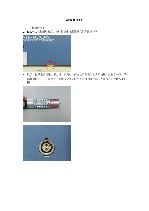
E3000使用手册一,开机前的准备1.E3000从包装箱取出后,使用前必须将底部黄色防震螺丝拧下。
2.然后,将吸枪正确连接至主机,必要时,在连接后稍微用力将吸枪接头往里顶一下,确保其密封性。
注:吸枪与主机连接必须保持两者的方向性一致,可参考其定位键及定位槽。
3.最后,将带接地连接头的电源线连接至主机,便可以开机。
注:必须保证电源系统有接地连接,同时,工作电压范围在200---250伏。
二,检漏仪启动过程1.检漏仪在开启后,便进入自动启动的过程中2.当启动参数均正常的情况下,且无任何故障报警,仪器便进入正常的检漏模式。
三,检漏仪使用检漏仪在首次使用或长时间存放后的第一次使用,我司建议仪器在预热三十分钟以后执行一次校准。
如果仪器处于一直在使用状态,可以先操作半小时后,再执行校准。
校准包括两种:外部校准及内部校准。
外部校准:凡是与主机分离开的标准漏孔,执行时,我们都称之为外部校准。
外部标准漏孔外部校准执行过程:1.将E3000检漏仪正常连接启动。
仪器预热三十分钟以上后,执行外部校准。
2.选择显示器右上角CAL键进入校准过程。
3.检漏仪提示“选择校准气体”,例如:执行R134a校准。
气体1为R134a,选择右上角“GAS1”4.在确定所执行校准的气体类型后,仪器提示“开始外部校准”。
5.根据外置式标准漏孔漏率设置检漏仪上的参数。
例如:现有一个4.18g/a的R134a漏孔。
6.进入界面中的“编制漏率”,通过左边上下键将漏率修正至4.2g/a(由于修正值以0.05为一个单元,因此尽可能将数值靠近外置式标准漏孔漏率)。
7.确认后,准备开始校准。
8.将吸枪对准标准漏孔后按“起始”。
9.E3000将提示“吸外部校准漏孔,如讯号稳定请按OK”。
10.确认信号波动不大时,按OK。
此时,仪器将对信号进行采样处理,因此,在期间必须保证吸枪不能离开标准漏孔。
11.当提示“吸入空气”时,将吸枪移开标准漏孔,尽量使吸枪吸入新鲜空气。
泄漏测试仪操作说明

泄露测试仪说明书泄露测试仪在下列环境条件下可以绝对安全地使用:•室内使用•海拔3000公尺以下•周围操作温度从5°C到45°C•不会凝结的100%最大相对湿度•供应网络电压的波动不超过正常电压的15%•暂时过电压符合CEI664标准的安装类目II•CEI664标准的二级污染测试环境注意事项* 尽量保持测试环境清洁。
一般注意事项* 使用仪器前应阅读本使用手册。
* 所有与本仪器连接的电子装置必须依据其需要配备合乎标准的安全系统(保险丝﹑断路器…)。
* 为了避免电磁干扰,接到仪器的电线长度不应超过两公尺。
•电子主体必须接地线。
* 维修前请先拔掉与仪器相接的所有电子装置。
* 进行气动组件组合时应切断操作所需的空气供应* 当仪器通电后请勿打开它。
* 避免液体喷溅到仪器。
泄露测试仪简介泄露测试仪主要用来测试生产线上的气密零件,它们是特别为全自动和半自动工作台所设计。
其基本原理是测试两个充满相等压力的测试和标准零件之间差压的微小变化或下降。
原理图如下图1所示。
样品零件测试零件差压传感器压力传感器测试气体泄露仪用户?阀?阀图1它具有8开关量输入5继电器输出,配合系统的用户自定义编程,可以接受外部信号的控制,同时可以控制电磁阀、继电器等元件,从而轻松实现设备的全自动化。
测试特性:2.1差压测试测试范围精度最大分辨率0~1000Pa 满量程的3% 0.25pa0~10000Pa 满量程的3% 2.5pa2.2测试压力测试测试范围精度最大分辨率0~100KPa 满量程的1.5% 满量程的0.025%0~250KPa 满量程的1.5% 满量程的0.025%2.3机械调压阀0~400Kpa3.差压测试的主要类型有三种测试类型﹕直接测试﹑间接测试和密封零件测试。
这三种测试方法分别应用于压力下和真空条件下的测试。
其组态是依据应用而决定,且必须在仪器使用前设定。
3.1.直接/压降测试在测试和标准零件的压力被充到所要求的水平后,HRS泄露测试仪测试被平衡阀分开的两容积之间的差压。
泄漏测试仪操作规程(3篇)

第1篇一、目的为确保泄漏测试仪的正确使用,避免操作失误,保障操作人员安全,同时确保测试数据的准确性,特制定本操作规程。
二、适用范围本规程适用于所有使用泄漏测试仪的场合,包括但不限于工业生产、科研实验室、检测机构等。
三、责任者操作人员负责按照本规程进行操作,设备管理人员负责监督实施。
四、操作前的准备1. 环境检查:确保操作环境符合仪器要求,如温度、湿度、电源电压等。
2. 仪器检查:- 检查仪器外观是否有损坏、裂纹等异常情况。
- 检查仪器电源线和插头是否完好,连接是否牢固。
- 检查仪器显示屏、按键等是否正常工作。
3. 测试介质准备:根据测试需求,准备合适的测试介质,如气体、液体等。
4. 测试样品准备:确保测试样品表面干净,无污垢、油渍等。
五、操作步骤1. 开启仪器:- 按照仪器说明书开启电源,等待仪器自检完成。
- 确认仪器工作状态正常,显示屏显示清晰。
2. 设置测试参数:- 根据测试需求,设置测试压力、测试时间、测试介质等参数。
- 确认参数设置无误后,保存设置。
3. 进行测试:- 将测试样品放置在测试腔体内,确保样品与测试腔体接触良好。
- 启动测试程序,仪器开始进行泄漏测试。
- 观察仪器显示屏,实时监控测试数据变化。
4. 数据记录:- 测试过程中,记录测试压力、测试时间、泄漏量等数据。
- 测试完成后,保存测试数据。
六、注意事项1. 安全操作:- 操作过程中,佩戴防护用品,如手套、护目镜等。
- 避免接触仪器高电压、高电流部分。
- 操作人员应熟悉仪器操作,确保操作正确。
2. 环境要求:- 操作环境应保持干燥、通风,避免潮湿、腐蚀性气体等。
- 操作过程中,注意避免碰撞、震动等。
3. 仪器维护:- 定期对仪器进行清洁、保养,确保仪器正常工作。
- 发现仪器故障,及时报修。
七、操作后的处理1. 关闭仪器:- 测试完成后,关闭仪器电源,确保仪器处于关闭状态。
2. 整理现场:- 清理测试现场,恢复原状。
- 清理测试样品,确保样品表面无污染。
制冷剂鉴别仪的使用
操作流程 •
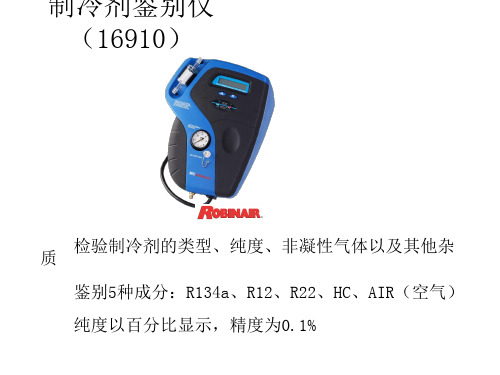
在预热的过程中,按住A、B键直到显示屏出现 “40U0S英AG尺E,EL相EV当AT于IO是N1,204米00)FE。ET”(出厂设置,海拔
• 使用A键和B键,调节海拔高度。
• 每按一次A键, 操升高作10流0英程尺
• 每按一次B键, 降低100英尺 • 常州地区的海拔高度为5米,因此设置成0英尺 • 设定完成后,静置20秒,自动切换到预热步骤
制冷剂鉴别仪 (16910)
质 检验制冷剂的类型、纯度、非凝性气体以及其他杂 鉴别5种成分:R134a、R12、R22、HC、AIR(空气) 纯度以百分比显示,精度为0.1%
制冷剂鉴别仪
ቤተ መጻሕፍቲ ባይዱ
(16910)
部件组成
主机
R134a样品软管
净化排放软管
R12样品软管
适配接头
电源线
仪器准备工作 • 1、检查采样管口
注:在预热过程中,如果不进行海拔高度设定,将 自动跳到系统标定环节
仪器的预热
• 预热操作界面
操作流程
2、海拔高度设定
操作流程
• 仪器在预热过程中显示“TO SET ELEVATION”。 表示没有输入海拔高度,需要输入海拔高度数值
• 如果不进行海拔高度设定,预热完成后将自动进 行系统标定。
• 海拔高度默认值是400英尺
3、系统标定
操作流程
操作流程
• 预热完成后, 系统标定自动进行,时间为1分钟
• 系统标定用于对仪器内部的测量元件进行归零, 同时排出残余的制冷剂
• 在系统标定过程中,仪器发出声音
操作流程
• 4、连接管路
旋钮
低压阀
快速接头
操作流程
• 检查样品出口处(即制冷系统的低压接头),确 保制冷剂应为气态,不允许有液态制冷剂或油 流出
制冷剂鉴别仪(16910)操作手册
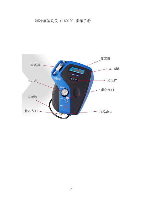
制冷剂鉴别仪(16910)操作手册一、操作前检查(1)检查仪器外面的圆柱形容器中的白色过滤芯上是否有红点。
任何红点的出现都说明过滤器需要更换,以避免仪器失效。
(2)根据需要选择一根R12 或R134a 采样管。
检查采样管是否有裂纹,磨损痕迹,脏堵或污染。
绝对不可以使用任何有磨损的管子。
把采样管安装到仪器的样品入口处。
(3)检查仪器头部的进空气口,再检查仪器中部边缘的样品出口,以确保它们没有堵塞。
(4)检查空调系统或制冷剂罐上的样品出口处,确保出口处样品为气态,出口不允许有液态样品或油流出来。
(5)将仪器的电源接头连接到车载电源或市电电源上。
通过夹子用车载电源供电(10-14 伏)或墙上的市电电源(22V)插座供电。
二、操作步骤(1)给仪器通电,仪器自动开机。
(2)让仪器预热两分钟。
(3)在预热过程中,需要将当地的海拔高度输入到仪器的内存中。
仪器可以在海拔高度变化为152 米(500 英尺)的范围内自动调节,所以初次使用时必须输入当地的海拔度高。
正常的气压变化不会影响仪器的运行。
一般情况下只需输入一次海拔高度,只有当仪器在另一个海拔高度的地方使用时才需要重新输入海拔高度。
①如果没有输入海拔高度,仪器在预热过程中会显示“ USAGE ELEVATION NOTSET”。
按照如下步骤设置海拔高度:②在预热过程中,按住B 按钮直到显示屏出现“USAGE ELEVATION,400FEET”(这是仪器的出厂设置,相当于海拔122 米)。
③使用A和B按钮来调节海拔高度的设置,直到显示的读数高于但最接近当地的海拔值(图1)。
每按一下A 按钮读数增加30 米(100 英尺),每按一下B 按钮读数减少30 米(100 英尺)。
海拔高度在0 到2730 米(0-9000 英尺)之间都是可调的。
图1④当选择好正确的海拔高度后,不要再按A 和B 按钮,保持仪器处于待机状态约20 秒,设置会自动保存到仪器的内存中。
注意:错误的海拔高度输入将导致仪器的检测错误。
Model RLD2 冷却漏气检测器设施安装和操作说明说明书

Model RLD2 Refrigerant Leak DetectorSpecifications - Installation and Operating InstructionsBulletin TE-RLD2 The Model RLD2 Refrigerant Leak Detector is the most dependable negativecorona refrigerant leak detector. The responsive elements have a wide sensitivityrange. This unit utilizes a five level alarm system to detect excessive refrigerant inareas where there could be a potential leak. The dual-color LED indicator lightsprovide visual indication of the refrigerant gas concentration, various audio pitchesfacilitate detection, and its portable design is convenient for the user. The refrigerantleak detector can be utilized in residential and commercial refrigeration systems,automotive, air conditioning, and quality control testing environments.TECHNICAL FEATURESThis device consumes low power by utilizing an 8–bit microprocessor controller. Alsoequipped is dual-colored LED indicator light with progressive and real time display.The sensitivity is adjustable with seven level alarming indicated by the audio levels andLED display. The indicators are convenient for maintenance because of the modular sensor, battery voltage indication and auto rest testing when the detector is turned on. OPERATION KEYS• ON/OFF KeyPress it to turn on/off the detector.• SENS KeyIt is the sensitivity adjustment key, it can adjust the sensitivity level according to the detection demands (max level:7). LED light will indicate the level of sensitivity, meanwhile the frequency of audible alarm changes. The higher the sensitivity level, the faster the alarm frequency.• RESET KeyReset the background halogen level to “zero”, any leak sources higher than “zero”level is considered to be a leak and trigger the alarm.Before Operating the Leak Detector:In order to detect leaks in a refrigerant system, the system must have normal operating pressure, or at least reach a minimum of 50 PSI. Low environmental temperature (lower than 59°F or 15°C) may lower the system required pressure and may make the leak less likely to be detected. No leak detected does not mean the system does not have a refrigerant gas leak. Check the pressure before making the conclusion. Leaking areas are usually covered with contaminants such as a compressor oil or dirt, be careful not to let the sensor tip touch with these contaminants. This product’s function is to detect halogen’s relative change at the sensor tip. Pinpointing the leak source needs to be done manually by adjusting the sensitivity and resetting thedetector by the user.®Printed in U.S.A. 2/19FR# 444134-00 Rev. 2©Copyright 2019 Dwyer Instruments, Inc.OPERATION1. Turn the detector on by pressing the ON/OFF key. All LED indicator lights will be on for 3 seconds, and the detector will automatically reset. A rapid, steady beep will also be heard.2. After the auto-reset, only the first LED indicator light on the left will be on. This is the power indicator light (see battery voltage indication section for more information).3. Begin searching for leaks. When refrigerant is detected, an audible buzzer will sound with a different rate than the previous beeping sound. Also, the indicator lights will progressively turn on.4. The sensitivity cap can be adjusted at any time during operation by pressing the SENS key. This adjustment will not interrupt detection. The default sensitivity level is level5.5. If an alarm occurs before the sensing tip touches the leakage source, press the RESET key to reset the current to zero until there is no alarm, then continue detecting.6. When done using, press the ON/OFF key to turn off the detector.Detecting Method1. Visually examine the refrigeration system. The oily and dirty spots, node valves, coils, connectors, or pipelines are the areas most likely to leak gases.2. Start leak detecting at the joint at a distance of about 1 to 3 cm, moving at a speed of about 1 cm/s.3. When an alarm is triggered, it may indicate a leak is close by. Detect around that area again and see if the alarm is repeatable. If a leak is confirmed, pinpoint the leak source by moving slowly from the non-leaking to the leaking area from different directions. Another method to pinpoint the leak is to move the detector away from the leaking area, reset the unit, and repeat the above process. Once confirmed, mark around the leak and continue detecting the whole line of the system.4. Additional work may be needed to eliminate possible ambiguity, such as other contaminants in the area of the leak. Clean the leaking area with a dry cloth and blow with clean, dry air, and repeat step 3 to confirm the leak.Recommendations Based on EnvironmentDepending on the environment around the leak, different methods may need to be used to detect properly.1. In areas where the atmosphere is contaminated with the refrigerant, press the RESET key to make the detector ignore the leak in the background. Make sure not to move the sensor tip away from the contaminated background while resetting the detector.2. In windy areas, the leaked halogen refrigerant may be quickly diluted or removed from the leak source. The user may use a wind shield to isolate the leak area or temporarily turn off the fan.3. To avoid false alarm, prevent the sensor tip from touching any moisture or other solvent.Battery Voltage IndicationUsers can check the battery level in the standby mode from the battery level indicator light. The color of the power indicator light will change according to the battery level. The indication of the colors are:Green Meets requirement for normal work. Orange Low battery working voltage.Red Below the permitted working voltage. Please replace the batteries as soon as possible.Battery Replacement1. Push open the battery door located at the bottom of the detector, then remove the door.2. Install two AA batteries into the detector, paying attention to the polarity marking on the side of the case, and then place the battery door back.MAINTENANCEProper maintenance is important and may extend the service life and improve the performance of your detector.Keep the sensor tip clean: Use cotton cloth or dry air to clean the shield on the sensor tip if it gets contaminated. If the sensor tip itself is contaminated, soak the tip in absolute alcohol for a few minutes, and then use compressed air to blow it dry or dry it with cloth. Note: Never use strong solvents such as gasoline, mineral oil, or turpentine, as these solvents may coat the sensor with a thin film and reduce the sensitivity of the detector making the detector slow to respond to a leak. Put the detector and the tip in a dry and clean place; remove the batteries if the detector is not used for a long time. REPAIR/WARRANTYModel RLD2 is not field serviceable and should be returned if repair is needed. Field repair should not be attempted and may void warranty. Refer to “Terms and Conditions of Sale” in our catalog and on our website. Contact customer service to receive a Return Goods Authorization number before shipping the product back for repair. Be sure to include a brief description of the problem plus any additional application notes.To reduce the risk of igniting flammable gases in a closed atmosphere, batteries must only be replaced in an open area orclosed space without flammable gas.Turn the power off before replacing the sensor tip. Voltage across the tip may pose an electrical hazard.。
红外制冷剂检漏仪操作手册说明书

Infrared RefrigerantLeak DetectorCFCs, HFCs, HCFC Blends,and HFO-1234YFOperator’s ManualPatent 7,022,993March 31, 2017P/N: 0019-9372Revision 1 Product Leadership ∙ Training ∙ Service ∙ ReliabilityTru Pointe® IR Refrigerant Leak DetectorWarrantyBacharach, Inc. warrants to Buyer that at the time of delivery this Product will be free from defects in material and manufacture and will conform substantially to Bacharach Inc.’s applicable specifications. Bacharach’s liability and Buyer’s remedy under this warranty are limited to the rep air or replacement, at Bacharach’s option, of this Product or parts thereof returned to Seller at the factory of manufacture and shown to Bacharach Inc.’s reasonable satisfaction to have been defective; provided that written notice of the defect shall have been given by Buyer to Bacharach Inc. within one (1) year after the date of delivery of this Product by Bacharach, Inc.Bacharach, Inc. warrants to Buyer that it will convey good title to this Product. Bacharach’s liability and Buyer’s remedy under this warranty of title are limited to the removal of any title defects or, at the election of Bacharach, to the replacement of this Product or parts thereof that are defective in title.THE FOREGOING WARRANTIES ARE EXCLUSIVE AND ARE GIVEN AND ACCEPTED IN LIEU OF (I) ANY AND ALL OTHER WARRANTIES, EXPRESS OR IMPLIED, INCLUDING WITHOUT LIMITATION THE IMPLIED WARRANTIES OF MERCHANTABILITY AND FITNESS FOR A PARTICULAR PURPOSE: AND (II) ANY OBLIGATION, LIABILITY, RIGHT, CLAIM OR REMEDY IN CONTRACT OR TORT, WHETHER OR NOT ARISING FROM BACHARACH’S NEGLIGENCE, ACTUAL OR IMPLIED. The remedies of the Buyer shall be limited to those provided herein to the exclusion of any and all other remedies including, without limitation incidental or consequential damages. No agreement varying or extending the foregoing warranties, remedies or this limitation will be binding upon Bacharach, Inc. unless in writing, signed by a duly authorized officer of Bacharach.ALL GOODS MUST BE SHIPPED TO BACHARACH BY PREPAID FREIGHT. ALL RETURNED GOODS MUST BE PRE-AUTHORIZED BY OBTAINING A RETURN MERCHANDISE AUTHORIZATION (RMA) NUMBER. CONTACT BACHARACH FOR A NUMBER AND PROCEDURES REQUIRED FOR PRODUCT TRANSPORT.Register Your Warranty by VisitingProduct improvements and enhancements are on-going, therefore the specifications and information contained in this document may change without notice. Bacharach, Inc. shall not be liable for errors contained herein or for incidental or consequential damages in connection with the furnishing, performance, or use of this material. No part of this document may be photocopied, reproduced, or translated to another language without the prior written consent of Bacharach, Inc.Copyright © 2014-2017, Bacharach, Inc.All rights reserved.BACHARACH® is a registered trademark of Bacharach, Inc. All other trademarks, trade names, service marks and logos referenced herein belong to their respective owners.Tru Pointe IR Refrigerant Leak DetectorTABLE OF CONTENTSSECTION 1.INTRODUCTION (4)1.1. Product Overview (4)1.2. General Safety Precautions (5)1.3. Lithium Battery Care and Safety (5)1.4. Components (6)1.5. Specifications (7)SECTION 2.OPERATION (8)2.1. Charging the Lithium-Ion Battery (8)2.2. Buttons 92.3. LED Indicators (10)2.4. Sensitivity Settings (11)2.5. Probe Selection (12)2.6. Leak Detection (12)SECTION 3.MAINTENANCE (15)3.1. Filter Replacement (15)3.2. Replacement Parts and Accessories (15)Tru Pointe® IR Refrigerant Leak Detector SECTION 1. INTRODUCTION1.1. Product OverviewTru Pointe®IR is a hand-held refrigerant gas detector that uses infrared technology and combines sensitivity, portability, and ease of use to detect CFCs, HFCs, HCFC blends, and HFO-1234YF in HVAC/R applications. Features include the following:∙Sensitivity <0.1 oz/yr (3 g/yr) (exceeds SAE J2791 standard)∙Adjustable squelch feature (low, medium, and high sensitivity)∙Additional Background Mode for maximum sensitivity to pick up low-level leaks in areas heavily contaminated with refrigerant∙Never needs to be calibrated (automatically adjusts to ambient conditions of an area that may have background refrigerant gases present)∙LED bar graph display with audible feedback and mute option∙Peak reading display∙Rechargeable lithium-ion battery with low battery alert∙Dual charging capabilities (AC adapter and DC cigarette lighter)∙Rugged housing with rubber boot and magnetic clip∙15” flexible probe with a 9” flexible extension and 9” rigid extension∙Replaceable filter (limits moisture and contaminants)∙30-second self-test and calibration at start-up∙Molded plastic carrying case.Figure 1. Tru Pointe® IRTru Pointe® IR Refrigerant Leak Detector1.2. General Safety PrecautionsKNOW YOUR EQUIPMENT! Before operating this unit, please read thismanual in its entirety. It is important that you have a thoroughunderstanding of the procedures outlined in this manual. Failure tofollow these procedures could void all manufacturer warranties. Also,read and understand the labels affixed to the unit. Learn theapplication and limitations as well as the specific potential hazards ofyour equipment.CAUTION! Avoid breathing high concentrations of refrigerant vapors.Inhalation of high concentrations is harmful and may cause heartirregularities, unconsciousness, or death.WARNING! To prevent personal injury and/or equipment damage:∙Read, understand, and follow all warnings stated in the Lithium Battery Care section of this manual.∙DO NOT charge the battery with any charger other than the chargers supplied with the unit.∙DO NOT use the instrument without a clean filter correctly installed in the tip.∙DO NOT draw moisture in through the probe.1.3. Lithium Battery Care and SafetyThe Tru Pointe® IR instrument operates on a lithium-ion type NP-120 battery. To promote the longest possible battery life and safe operation, and to prevent personal injury and/or equipment damage, observe all warnings.WARNING!Do not disassemble or attempt to repair the battery orprotective circuit.WARNING! Do not expose the battery to temperatures above 140︒ F(60︒ C).WARNING! Do not charge the battery near a fire or in a hot vehicle orin direct sunlight.WARNING! Do not solder directly on the battery.WARNING! Do not subject the battery to impact.Tru Pointe® IR Refrigerant Leak DetectorWARNING!Do not expose the battery to moisture or immerse it in fluid.WARNING! Do not deform, pierce, or damage the battery.WARNING!Do not touch a battery that is leaking electrolytes. If battery fluid should get in your eyes, flush with fresh water, do not rub eyes, and see a physician immediately.WARNING! Do not use a battery if it is deformed, smells bad, changes color, or appears abnormal. Return the unit for a replacement battery immediately.1.4. ComponentsFigure 2. Tru Pointe® IR ComponentsTru Pointe® IR Refrigerant Leak Detector 1.5. SpecificationsTru Pointe® IR Refrigerant Leak Detector SECTION 2. OPERATION2.1. Charging the Lithium-Ion BatteryIMPORTANT! Avoid discharging the battery completely. Recharging a partially discharged battery more frequently is better for the life of a lithium-ion battery.To recharge the Tru Pointe® IR instrument follow the instructions below.Figure 3. AC (Wall Outlet) and DC (Vehicle) Chargers Plug one end of the charger into the power source (wall outlet or acar’s cigarette lighter outlet).NOTE! When the battery is low, the LOW-BATT LED will illuminate.IMPORTANT!Be sure to fully charge the battery before using the instrument for the first time. The unit was packaged and shipped from the factory with the battery only partially charged.Tru Pointe IR Refrigerant Leak Detector2.2. ButtonsFigure 4. ButtonsTru Pointe® IR Refrigerant Leak Detector 2.3. LED IndicatorsFigure 5. LED Indicators2.4. Sensitivity SettingsThe Tru Pointe® IR has four sensitivity settings used to detect refrigerant leaks: Low, Medium, High (default at start-up), and Background.Use the high sensitivity setting to detect refrigerant leaks as small as 0.1 oz/yr (3 g/yr). Medium and low sensitivity settings can also be used for progressively larger leaks. Change this setting using the L/M/H button based on your preference, suspected leak type, and particular application. Consecutive presses of the L/M/H button will toggle the instrument through these three modes.NOTE! Generally, a retest is advisable when a leak is discovered usingthe most sensitive settings or if the probe was in a static position whenthe leak was discovered. In these cases, repeat the test ensuring theprobe moves past the suspected leak location while maintaining thesmallest possible gap between the suspected leak point and the tip ofthe probe. Also, consider using the Medium sensitivity position of thedetector after finding an apparent leak with the High sensitivity setting.A fourth sensitivity setting is Background Mode. Background Mode is the most sensitive operating mode of the Tru Pointe® IR. In this mode, the instrument will trigger on extremely small refrigerant levels as well as sudden probe movements.∙With the instrument in High sensitivity mode, quickly press the Peak button 4 times in succession to put the Tru Pointe® IR into BackgroundMode∙The first (left most) LED in the bar graph display will blink quickly when in Background Mode∙The leak detection tone will change from a tick to a steady tone when in Background Mode∙To exit the Background Mode, quickly press the PEAK button 4 times in succession, or switch from High sensitivity mode to one of the otherlevels.2.5. Probe SelectionThe Tru Pointe®IR has a 15"(38.1 cm) flexible probe. For applications requiring additional reach, this probe may be extended using the 9" (22.9 cm) flexible probe extension. For targeted detection in confined locations, the 9"(22.9 cm) rigid “needle” probe extension may be used. Use an O-ring between probes, the probe tip, and any extensions (if used).Figure 6. Flexible and Rigid Probe Extensions2.6. Leak DetectionNOTE! The Tru Pointe® IR instrument detects changes in concentrationof refrigerant, not the absolute concentration of refrigerant. Thisallows the detection of leaks in locations that may have refrigerant inthe air, however, be sure to keep the probe tip moving during testing.NOTE! Some leaks may not be measurable if the pressure in the HVACsystem is too low. In such cases, you may need to charge the systemwith sufficient refrigerant to have a gauge pressure of at least 340 kPa(50 psi) with the system off.WARNING! The Tru Pointe® IR instrument is sensitive and can take upto 30 seconds to clear after detecting a small amount of contaminant.It will typically clear in 2 to 15 seconds.WARNING!Do not use cleaning agents or solvents on or near A/Clines. Wipe away any dirt or potential false-trigger chemicals using adry towel.To perform refrigerant leak detection, follow the instructions below.NOTE! Use shop air or compressed air to quickly clear a suspected area of refrigerant build-up, and then re-test. Do not use commercially available “canned” air to clear refrigerant build -up as it uses refrigerant as a propellant and will further contaminate the immediate area.Figure 7. Probe “Sweeping” Method for Detecting Refrigerant LeaksFigure 8. Sample Refrigerant Path for Testing LeaksSECTION 3. MAINTENANCE3.1. Filter ReplacementA filter located in the tip of the wand blocks moisture and other contaminants from the sensor. When this filter becomes wet, it restricts the flow of air and must be replaced. To replace the filter, follow the steps below.NOTE! Use only replacement filters supplied by Bacharach.3.2. Replacement Parts and AccessoriesWorld Headquarters621 Hunt Valley Circle, New Kensington, Pennsylvania 15068 Phone: 724-334-5000 • Toll Free: 1-800-736-4666 • Fax: 724-334-5001Website: • E-mail:********************。
泄漏电流测试仪使用说明

泄漏电流测试仪使用说明一、仪器概述二、仪器操作步骤1.接线准备将泄漏电流测试仪的电源线插入标准电源插座。
根据测试设备的类型选择合适的测试线缆,将测试线缆的一个端口插入泄漏电流测试仪的测试接口,另一个端口连接到待测设备的测试点或电源插座。
2.仪器开机打开泄漏电流测试仪的电源开关,仪器将开始初始化,并显示系统状态。
在一段时间后,待测设备的泄漏电流数值将显示在仪器的屏幕上。
3.设置参数根据测试需要,设置仪器的参数。
如设定测试电压、测试时间、测试模式等。
测试电压是指施加到待测设备上的电压大小,一般可选择低电压(例如50V)或高电压(例如500V)。
测试时间是指持续施加电压的时间,一般可选择几秒到几分钟。
测试模式可以选择自动模式或手动模式,自动模式下仪器会自动进行测试并记录结果,手动模式下需要用户手动触发测试。
4.进行测试确认参数设置正确后,按下测试开始按钮,泄漏电流测试仪将开始施加电压到待测设备上,并开始测量泄漏电流。
在测试过程中,仪器将显示当前测量数值,并在测试结束后显示测试结果。
5.处理测试结果根据需要,将测试结果记录下来或导出到计算机进行进一步处理。
一般来说,泄漏电流是一个相对的数值,所以需要与设备的规格进行比较。
如果测试结果超过了设备规定的泄漏电流范围,说明设备存在泄漏问题,需要进行修理或调整。
三、注意事项1.在进行测试之前,应确保仪器和待测设备的连接正确,并保证连接线缆的质量良好,以免影响测试结果。
2.在测试过程中,应注意安全防护,避免触电风险。
禁止用湿手或脱漆的导线进行测试。
3.在测试之前,应检查待测设备的外部线路是否正确,避免因线路故障导致测试结果不准确。
4.使用仪器时,应按照仪器的规定操作,严禁擅自拆卸或改变仪器的内部结构。
5.使用完毕后,应将仪器关闭并拔掉电源线,以免长时间不使用造成损坏。
冷媒检漏仪的使用方法
冷媒检漏仪的使用方法
冷媒检漏仪是一种用于检测制冷设备中冷媒泄漏的工具,它可以帮助用户快速
准确地定位泄漏点,保障设备安全运行。
使用冷媒检漏仪需要注意一些方法和步骤,下面将为大家详细介绍。
首先,使用冷媒检漏仪之前,需要确保设备处于关闭状态,以免对设备造成任
何干扰或损坏。
接下来,将冷媒检漏仪的探测探头连接到设备上,确保连接牢固,以免出现松动导致误差。
在连接好探测探头后,我们需要对冷媒检漏仪进行一些基本设置,例如选择检
测模式、设定灵敏度等。
这些设置将直接影响到检测的准确性和效果,因此需要仔细操作,确保符合实际需求。
接下来,我们可以开始使用冷媒检漏仪进行检测了。
在检测过程中,需要将探
测探头移动到设备表面的不同区域,特别是容易泄漏的部位,如接头、焊缝等。
同时,还需要留意检测仪器上的指示灯和显示屏,及时发现并记录泄漏信号。
在检测完成后,需要对检测结果进行分析和处理。
如果发现了泄漏点,需要及
时进行修复和处理,以免造成更大的损失。
如果未发现泄漏,也需要对设备进行一些维护和保养,确保设备的正常运行。
最后,使用完冷媒检漏仪后,需要对设备和检测仪进行清洁和保养。
清洁设备
可以延长其使用寿命,保持其检测效果;而清洁检测仪可以避免因灰尘或污垢影响其准确性。
总的来说,使用冷媒检漏仪需要注意一些方法和步骤,包括设备的准备、基本
设置、检测操作、结果处理和设备清洁。
只有严格按照这些步骤进行操作,才能确保检测的准确性和设备的安全运行。
希望以上内容可以帮助大家更好地掌握冷媒检漏仪的使用方法,保障设备的安全运行。
泄漏仪操作规程(3篇)

第1篇一、概述泄漏仪是一种用于检测管道、设备或容器等系统中泄漏的仪器,广泛应用于化工、石油、电力、燃气等行业。
为确保操作人员的安全和检测结果的准确性,以下为泄漏仪的操作规程。
二、操作前准备1. 人员培训:操作人员应接受专业培训,熟悉泄漏仪的结构、原理、操作方法和注意事项。
2. 设备检查:检查泄漏仪的外观是否完好,电源、传感器、探头等部件是否正常。
3. 环境准备:确保检测现场通风良好,避免高温、潮湿、腐蚀等不良环境。
4. 检测介质:根据检测介质的性质选择合适的传感器和检测范围。
三、操作步骤1. 开启仪器:接通电源,开启泄漏仪。
2. 设置参数:根据检测要求设置检测范围、报警阈值等参数。
3. 安装传感器:将传感器正确安装在检测管道或设备上,确保传感器与检测面紧密接触。
4. 探头校准:使用标准泄漏源对探头进行校准,确保检测精度。
5. 检测:开启检测功能,开始对管道或设备进行泄漏检测。
6. 数据分析:观察泄漏仪的显示屏,分析检测结果,记录泄漏位置、泄漏量等信息。
四、注意事项1. 安全操作:操作人员应穿戴适当的个人防护装备,如防毒面具、防护服等。
2. 避免干扰:检测过程中,避免使用手机、电磁设备等可能产生干扰的物品。
3. 防止误报:在检测过程中,注意观察周围环境,避免误报。
4. 定期维护:定期对泄漏仪进行维护保养,确保其正常运行。
5. 数据记录:详细记录检测过程、检测结果等信息,便于后续分析和追踪。
五、异常情况处理1. 仪器故障:若发现泄漏仪出现故障,应立即停止检测,联系维修人员进行检查和维修。
2. 泄漏报警:若检测到泄漏,应立即采取相应措施,如关闭泄漏点、隔离泄漏区域等。
3. 人员伤害:若操作人员出现身体不适,应立即撤离现场,寻求医疗救助。
六、操作结束1. 关闭仪器:检测结束后,关闭泄漏仪,断开电源。
2. 清理现场:清理检测现场,确保安全。
3. 整理资料:整理检测报告、数据等信息,存档备查。
本规程旨在规范泄漏仪的操作,确保检测工作的安全、准确和高效。
冷媒检漏仪的使用方法

冷媒检漏仪的使用方法冷媒检漏仪是一种专门用于检测冷却系统中冷媒泄漏的设备。
在冷却系统中,冷媒的泄漏问题是非常常见的,如果不及时发现和修复,不仅会导致制冷效果下降,还可能对环境造成污染。
因此,掌握冷媒检漏仪的使用方法是非常重要的。
使用冷媒检漏仪之前,需要确保设备已经接通电源并处于正常工作状态。
检漏仪通常会有一个开关按钮,将其打开即可开始使用。
在启动检漏仪之前,还需要检查设备是否已经连接到待检测的冷却系统上。
通常情况下,冷媒检漏仪会通过一个特定的接口与冷却系统连接,确保连接牢固可靠。
接下来,我们需要调整冷媒检漏仪的灵敏度。
不同的冷媒泄漏情况可能需要不同的灵敏度设置。
一般而言,灵敏度越高,检测到的泄漏量越小。
在冷媒检漏仪上,通常会有一个调节旋钮或按钮用于设置灵敏度。
根据实际情况,将灵敏度调整到适当的位置。
当冷媒检漏仪准备就绪后,我们可以开始进行泄漏检测了。
首先,需要选择一个检测点,通常是冷却系统的连接口或其他易泄漏的部位。
将冷媒检漏仪的探头放置在检测点上,并保持稳定。
然后,观察冷媒检漏仪的显示屏,通常会有一个数字或图表显示当前的泄漏量。
如果泄漏量超过了设定的灵敏度阈值,冷媒检漏仪会发出声音或光信号进行警示。
在检测过程中,需要注意一些细节。
首先,要确保检测环境的温度和湿度适宜。
过高或过低的温度都可能影响冷媒检漏仪的准确性。
此外,还要注意避免检测过程中的干扰。
比如,当附近有其他电子设备或强烈的电磁场时,可能会对冷媒检漏仪的工作产生干扰,导致误报或漏报。
除了以上的基本使用方法外,还有一些额外的使用技巧可以提高冷媒检漏仪的效果。
首先,可以使用氮气进行辅助检测。
将氮气注入冷却系统中,通过冷媒检漏仪检测氮气的泄漏情况,可以更准确地确定冷却系统的泄漏点。
此外,还可以利用冷却系统的压力变化情况来判断泄漏位置。
当冷却系统中的压力发生变化时,冷媒检漏仪会显示出相应的泄漏信号。
冷媒检漏仪是一种非常实用的设备,可以帮助我们及时发现和修复冷却系统中的冷媒泄漏问题。
泄漏检测仪操作说明书JT-1A

JT-1A地下管线泄漏探测仪用户操作手册扬州捷通供水技术设备有限公司目录1.前言 (1)1.1概述 (2)1.2注意事项 (2)1.2.1警告事项 (3)1.2.2注意事项 (3)1.3技术参数 (4)1.4技术术语 (5)1.4.1滤波器 (5)1.4.2陷波器 (5)1.4.3最小值 (5)1.4.4水平柱状条 (6)1.4.5模式旋钮 (6)2.仪器组成 (7)2.1仪器部件组成 (7)2.2硬件组成部件 (8)2.2.1主机 (8)2.2.2控制手柄 (11)2.2.3传感器 (12)2.2.4耳机 (13)2.2.5电池组与充电器 (14)3.使用检测仪 (15)3.1仪器安装 (15)3.2使用前检查 (16)3.3开机流程 (17)3.4开机页面 (18)3.5等待页面 (18)3.6检测页面 (19)4.泄漏探测方法 (20)4.1沿管线探测 (20)4.2定位泄漏点 (22)4.3频散对泄漏定位的影响 (23)5.疑难解答 (24)1.前言非常感谢您选择使用JT-1A地下管线泄漏探测仪。
本说明书详细阐述了如何操作和使用JT-1A地下管线泄漏探测仪。
本说明书详细描述了JT-1A地下管线泄漏探测仪的组成、功能、操作方式、注意事项以及使用探测仪进行埋地管道泄漏探测的方法。
请您在操作或使用本仪器之前务必仔细阅读并完全理解本操作说明书中的内容。
如果您对JT-1A地下管线泄漏探测仪在操作和使用上有任何疑问,可随时拨打我公司电话(0514)87236231,我们会向您提供及时而热诚的技术支持和服务。
谢谢合作!请您妥善保管本说明书以便需要时使用,如有说明书遗失或损坏,请您立即联系我公司。
1.1概述JT-1A地下管线泄漏探测仪通过传感器拾取地下压力管道破损泄漏所产生的振动信号来准确定位泄漏点的位置。
本泄漏检测仪配置了适应不同检测环境的传感器,从而能有效地实现泄漏点的检测与定位。
通过选择该检测仪器中配置的16组频段组合中的任何一组频段来检测泄漏信号,以满足不同材质/管径管道、不同工作地段(埋层介质)的泄漏检测需要。
Fieldpiece RFE2 和 RRE2 绝缘式冷氩泄漏检测器说明书

Tel (714) 634-1844 Fax (714) 634-1848
What’s Included With Both Detectors
· Wall charger
· Leak detector
· 9-inch flex extension
Gases measured: CFC, HFC, HCFC blends.
Sensing element: Infrared
Sensor life:
10 years
Response time: Less than 1/2 second to 1 second.
Accuracy:
Exceeds current SAE standards.
Premium Refrigerant Leak Detectors Test Tools HVACR Pros Trust
INFRARED
State-of-the-Art Infrared Sensor Sensitivity Below 0.1 oz/yr. 8-hour Lithium Battery
Sensitivity levels: (per SAE standards)
TURBO: Less than 0.1 oz /year HIGH: 0.1 oz./year and higher MEDIUM: 0.5 oz./year and higher LOW: 1.0 oz./year and higher
Amprobe RLD-1 冷却液泄漏检测器用户手册说明书

Users Manual • Mode d’emploi• Bedienungshandbuch• Manual d’Uso• Manual de usoRLD-1Refrigerant Leak DetectorRLD-1Refrigerant Leak Detector Users ManualJuly 2009, Rev.1©2009 Amprobe Test Tools.All rights reserved. Printed in TaiwanLimited Warranty and Limitation of LiabilityYour Amprobe product will be free from defects in materialand workmanship for 1 year from the date of purchase. This warranty does not cover fuses, disposable batteries or damage from accident, neglect, misuse, alteration, contamination, or abnormal conditions of operation or handling. Resellers are not authorized to extend any other warranty on Amprobe’s behalf. To obtain service during the warranty period, return the product with proof of purchase to an authorized Amprobe Test Tools Service Center or to an Amprobe dealer or distributor. See Repair Section for details. THIS WARRANTY IS YOUR ONLY REMEDY.ALL OTHER WARRANTIES - WHETHER EXPRESS, IMPLIED OR STAUTORY - INCLUDING IMPLIED WARRANTIES OF FITNESS FORA PARTICULAR PURPOSE OR MERCHANTABILITY, ARE HEREBY DISCLAIMED. MANUFACTURER SHALL NOT BE LIABLE FOR ANY SPECIAL, INDIRECT, INCIDENTAL OR CONSEQUENTIAL DAMAGES OR LOSSES, ARISING FROM ANY CAUSE OR THEORY. Since some states or countries do not allow the exclusion or limitation of an implied warranty or of incidental or consequential damages, this limitation of liability may not apply to you.RepairAll test tools returned for warranty or non-warranty repair orfor calibration should be accompanied by the following: your name, company’s name, address, telephone number, and proof of purchase. Additionally, please include a brief description of the problem or the service requested and include the test leads with the meter. Non-warranty repair or replacement charges should be remitted in the form of a check, a money order, credit card with expiration date, or a purchase order made payable to Amprobe® Test Tools.In-Warranty Repairs and Replacement – All CountriesPlease read the warranty statement and check your battery before requesting repair. During the warranty period any defective test tool can be returned to your Amprobe® Test Tools distributorfor an exchange for the same or like product. Please check the “Where to Buy” section on for a list of distributors near you. Additionally, in the United States and Canada In-Warranty repair and replacement units can also be sent to a Amprobe® Test Tools Service Center (see address below).Non-Warranty Repairs and Replacement – US and CanadaNon-warranty repairs in the United States and Canada should be sent to a Amprobe® Test Tools Service Center. Call Amprobe® Test Tools or inquire at your point of purchase for current repair and replacement rates.In USA In CanadaAmprobe Test Tools Amprobe Test ToolsEverett, WA 98203 Mississauga, ON L4Z 1X9Tel: 877-AMPROBE (267-7623) Tel: 905-890-7600Non-Warranty Repairs and Replacement – EuropeEuropean non-warranty units can be replaced by your Amprobe® Test Tools distributor for a nominalv charge. Please check the “Where to Buy” section on for a list of distributors near you.European Correspondence Address*Amprobe® Test Tools EuropeIn den Engematten 1479286 Glottertal, GermanyTel.: +49 (0) 7684 8009 - 0*(Correspondence only – no repair or replacement available from this address. European customers please contact your distributor.)RLD-1 Refrigerant Leak Detector1234579101168SensorSensor ProtectorLED Leak IndicatorsSensitivity Lo ButtonPower On/OffReset ButtonSensitivity Hi ButtonLow Battery IndicatorBattery CoverBattery Cover Screw DC IN JackRLD-1 Refrigerant Leak Detector CONTENTS SYMBOLS (2)UNPACKING AND INSPECTION (2)INTRODUCTION (3)OPERATION (4)LED Leak Indicator Definition (4)Automatic Ambient Reset Feature (5)Feature Sensitivity Adjustment (6)How To Find Leaks? (7)SPECIFICATION (9)MAINTENANCE AND REPAIR (10)BATTERY REPLACEMENT (11)New Sensor Replacement (12)SYMBOLS�Caution! Refer to the explanation in this Manual �Conforms to relevant Australian standards�Complies with European Directives=Do not dispose of this instrument as unsorted municipal waste. Contact a qualified recycler fordisposal.�WARNING!Do not operate this instrument in the presenceof gasoline, natural gas, propane, or in othercombustible atmospheres.UNPACKING AND INSPECTIONYour shipping carton should include:2 Alkaline battery (2C Size)1 User Manual1 Carry Case1 AC Adaptor1 Leak Check BottleIf any of the items are damaged or missing, returnthe complete package to the place of purchase for anexchange.INTRODUCTIONRefrigerant Leakage Detector is the perfect tool for maintaining the air-condition or a cooling system with compressor and Refrigerant. This unit uses a newly developed semi-conductor sensor which is extremely sensitive to variety of general used Refrigerant • Microprocessor Control with advanced digitalsignal processing.• Multi color visual display.• High-median-Low leak sensitivity selector.• Low battery indication.• Semiconductor gas sensor.• Detection of R-134a, R-410A, R-407C, R22 Freon gas.• Carrying case included.• 15.5” (40 CM) flexible stainless probe.• Reference Leak source included.• Ambient concentration reset.• Long-life, DC brushless fan.• Automatic zero and background compensation.• AC Adapter:@3.3V 0.5AOPERATION1. The refrigerant leak detector unit is not equipped with anti-explosive designs and measures. Do not use this unit in the environment with the burnable gases.2. There are some environmental conditions that might cause error reading:• Pollutant places.• Large temperature variation.• Places with high wind velocity.• Organic solvent, adhesive vapor, fuel gas and vesicant will cause abnormal response from the sensor. Try to avoid the environment involved with this substance.• Places fill with too much to Freon Gas.LED Leak Indicator DefinitionPeriodically wipe the case with a damp cloth and mild detergent; do not use abrasives or solvents. If the meter is not to be used for periods of longer than 60 days, remove the battery and store separately.ConcentraionIndiction Concentraion IndictionAutomatic Ambient Reset FeatureThis Refrigerant leak detector features an Automatic Ambient Reset function that sets the unit to ignore ambient concentrations of refrigerant.• Automatic Ambient Setup - Upon initial poweron, the unit automatically sets itself to ignore thelevel of refrigerant present at the tip. Only a level,or concentration, greater than this will cause analarm.�CAUTION!Be aware that this feature will cause the unit toignore any refrigerant present at turn on. In otherwords, with the unit off if you place the tip up toa known leak and switch the unit on, no leak willbe indicated!• Ambient Reset Feature - Resetting the unit duringoperation performs a similar function it programsthe circuit to ignore the level of refrigerantpresent at the tip. This allows the user to ‘home-in’on the source of the leak (higher concentration).Similarly, the unit can be moved to fresh air andreset for maximum sensitivity. Resetting the unitwith no refrigerant present (fresh air) causes anylevel above zero to be detected.• After the unitis warmed up, the default sensitivity level is set at“Medium” and Auto Reset function is “ON”• Auto Reset function is best used initially whenuser is moving around trying to identify leakagesource. Once the leak source is determined, cancelthe Auto Detect function to proceed with leakagemeasurement.• Auto Reset function should be turned OFF whenuse in fixed position leakage detectionFeature Sensitivity AdjustmentThe Instrument provides three levels of sensitivity. When the unit is switched on, it is set to the Medium sensitivity level.• To change the sensitivity, press the “Lo” key.When the key is pressed, the visual display willmomentarily show the two bottoms LED’s (green)indicating Low Sensitivity level is selected.• To switch back to High Sensitivity, press the “Hi”key. The all LED’s (2 Green+2 Orange+3 Red) willlight momentarily indicating high Sensitivity levelis selected.Sensitivity level (Green LED)Sensitivity level(Orange LED)Sensitivity level(Red LED)How To Find Leaks?NOTE: A sudden whipping of the leak detector probeor “blowing” into the sensor tip will affect the air flow over the sensor and cause the instrument to alarm.(1) Power-Up keyThe + key turns the Refrigerant leak detectorinstrument ON or OFF function.Press it once to turn on the Refrigerant leakdetector, the display will illuminate with flash, for 45 seconds to heat up the sensor.Press and hold this button for 3 second to turn OFFthe power.(2) Auto Reset & Reset function keyWhen the Auto Reset function is turned ON, themeter will monitor background status and fine tune itself. When Reset LED light is on, it indicates it isin ON mode. Press “RESET” button and hold for 2seconds the Reset light will turn off and Auto Reset function is in OFF mode.When the Reset light is off, it indicates the Resetfunction is in manual mode. Press the “RESET”button once to enable manual Reset function.(3) Verify the condition of the unit and sensor• Set the sensitivity level to “Hi”.• Open the leak check bottle cover and slowlymove it closer to snake tube nozzle.• If the indication moves up to high from low thenwe should move the check bottle away and theLED should go off again. This shows that the unitis under working condition.• If the unit does not perform as we expect, bringthe unit for maintenance at your local salesoffice.(4) Enter the measuring mode• Place the tip of the leak-detector probe as closeas possible to the site of the suspected leak. Tryto position the probe within 1/4 inch (6 mm) ofthe possible leak source.• Slowly move the probe past each possibleleakage point.• When the instrument detects a leak source, theaudible tone will alarm. Additionally, the visualindicators will light from lower to higher; GreenLED then Orange LED then Red LED (highestconcentration) as increasing of level indicate thatthe location is close to the source.When the Instrument signals a leakage, pull the probe away from the leak for a moment, then bring it backto pinpoint the location. If the refrigerant leak is large, setting the sensitivity switch to LOW will make it easier to find the exact site of the leak.• Return the sensitivity switch to HIGH beforesearching for additional leaks.• When you’ve finished leak-testing, turn OFF theinstrument and store it in a clean place, protectthe leak detector from possible damage.SPECIFICATIONDetectable Gases : R-134a, R-404A, R-407C, R-410A, R-22 etcSensitivity :H M LR-22,134a 3g/year 15g/year 30g/yearR-404A, 407C, 410A 4g/year 20g/year 40g/yearAlarm Method : Buzzer, Tricolor LED bar Indicator Power Usage : 2 C size (3V DC) Alkaline BatteriesSnake Tube length : 40cm ( 15.5” )Dimension / Weight : 222 x 66 x 51 mm ( approximately 418g )Accessories : Alkaline batteries (C size) X 2 pcs User manual, leak check bottle, carry case, AC Adapter Battery Life : Approximately 16 hours normal use.Auto power OFF: 10 minutesDisable Auto Power Off : Press and Hold “Hi” button then power on the meter.Warm-Up Time : Approximately 45 secondsOperating Temperature & Humidity : 0 ~40 °C, < 80% RH Storage Temperature & Humidity : -10 ~60 °C, < 70% RH Altitude : < 2000M (6500’)� - EMC: Conforms to EN61326-1.This product complies with requirements of the following European Community Directives: 89/ 336/ EEC (Electromagnetic Compatibility) and 73/23/ EEC (Low Voltage) as amended by 93/ 68/ EEC (CE Marking). However, electrical noise or intense electromagnetic fields in the vicinity of the equipment may disturb the measurement circuit. Measuring instruments will also respond to unwanted signalsthat may be present within the measurement circuit. Users should exercise care and take appropriate precautions to avoid misleading results when making measurements in the presence of electronic interference.MAINTENANCE AND REPAIRIf there appears to be a malfunction during the operation of the meter, the following steps should be performed in order to isolate the cause of the problem.1. Check Batteries or replace batteries.2. Review the operating instructions for possiblemistakes in operating procedure.Except for the replacement of the battery, repair of the meter should be performed only by a Factory Authorized Service Center or by other qualified instrument service personnel.The front panel and case can be cleaned with a mild solution of detergent and water.Apply sparingly with a soft cloth and allow to dry completely before using. Do not use aromatic hydrocarbons, Gasoline or chlorinated solvents for cleaning.�WARNING!The detergent or isopropyl alcohol might damagethe sensor, please keep them from the sensorthrough the process.BATTERY REPLACEMENT• Loose the screw and remove the batterycompartment door located on the bottom of theinstrument as show below (Fig.1).• Install 2 “C” size alkaline batteries.• Reinstall the battery cover by aligning it with thehandle.When the batteries are nearing the end of their useful life, the Red LED Low Battery indicator illuminates. The batteries should be replaced as quickly as possible.Fig. 1New Sensor ReplacementThe sensor has a limited operative period. Under normal operation, the sensor should work more than one year. Expose the sensor under high density of coolant (>30000ppm) will shorten its life cycle rapidly. It is important to ensure that sensor surface is free from water droplets, vapor, oil, grease, dust and any or all other forms of contaminant. Furthermore, to ensure good working condition of the unit, sensors must be replacement periodically when its operative life is over.�CAUTION!When replacing new sensor, the worn-out sensormay be HOT!!(1) Remove cone cap cover from the tip of snake tube.(2) Pull out old sensor and insert the new sensor into the plug (Fig2).(3) Seal the cap cover over the plug.。
LDH-380冷却液泄漏检测器说明书

DD-xREFRIGERANT LEAK DETECTORLDH-380£113Microprocessor Control with Advanced Digital Signal Processing Multi-Color Visual DisplayHigh-Low LeakSensitivity Selector Low-Battery Indication Semiconductor Gas SensorDetection of R-134A, R-410A, R-407C and R22 Freon GasesCarrying Case Included 39 cm (15") Flexible Stainless Steel Probe Reference Leak Source IncludedAmbient Concentration ResetThe LDH-380 refrigerant leakage detector is the perfect tool for maintaining the air-condition or a cooling system with compressor and refrigerant. This unit uses a newly developed semi-conductor sensor which is extremely sensitive to variety of general refrigerants.SPECIFICATIONSDetectable Gases:R-134A, R-404A,R-407C, R-410A, R-22, etc.Sensitivity H L:R-22, 134A 6g/year 30g/year; R-404A, 407C, 410A 8g/year 40g/yearAlarm Method:Buzzer, tri-color LED bar indicatorPower Usage:4 “AA” size (6 Vdc)alkaline batteries (included)Battery Life:Approximately 40 hours normal useSnake Tube Length:39 cm (15")Auto Power OFF:10 minutesWarm-Up Time:Approximately 90 sec Operating Temperature and Humidity:0 to 40°C (32 to 104°F), <80% RHStorage Temperature and Humidity:-10 to 60°C (14 to 140°F), <70% RH Altitude:< 2000 m (6500')Dimensions:173 x 66 x 56 mm (6.8 x 2.6 x 2.2")Weight:Approximately 400 g (14 oz)Comes with 4 “AA” alkaline batteries, complete operator’s manual, leak check bottle and carrying case.Ordering Example: LDH-380,refrigerant leak detector for R-134A, R410A, R-407C, and R22 Freon gas,£113.LDH-380, £113.CANADA www.omega.ca Laval(Quebec)1-800-TC-OMEGA UNITED KINGDOM Manchester,England0800-488-488GERMANY www.omega.deDeckenpfronn,Germany************FRANCE www.omega.fr 088-466-342BENELUX www.omega.nl 0800-099-33-44UNITED STATES 1-800-TC-OMEGA Stamford,CT.CZECH REPUBLIC www.omegaeng.cz Karviná,Czech Republic596-311-899TemperatureCalibrators, Connectors, General Test and Measurement Instruments, Handheld Instruments for Temperature Measurement, Ice Point References, Indicating Labels,Crayons, Cements and Lacquers, Infrared Temperature Measurement Instruments, Recorders, Relative Humidity Measurement Instruments, PT100 Probes, PT100 Elements,Temperature & Process Meters, Timers and Counters,Temperature and Process Controllers and Power Switching Devices, Thermistor Elements, Probes and Assemblies,Thermocouples, Thermowells and Head and WellAssemblies, Transmitters, Thermocouple Wire, RTD ProbesPressure,Strain and ForceDisplacement Transducers, Dynamic Measurement Force Sensors, Instrumentation for Pressure and StrainMeasurements, Load Cells, Pressure Gauges, PressureReference Section, Pressure Switches, Pressure Transducers,Proximity Transducers, Regulators, Pressure Transmitters,Strain Gauges, Torque Transducers, ValvespH and ConductivityConductivity Instrumentation,Dissolved OxygenInstrumentation,Environmental Instrumentation,pH Electrodes and Instruments,Water and Soil Analysis InstrumentationHeatersBand Heaters,Cartridge Heaters,Circulation Heaters,Comfort Heaters,Controllers,Meters and SwitchingDevices,Flexible Heaters,General Test and Measurement Instruments,Heater Hook-up Wire,Heating Cable Systems,Immersion Heaters,Process Air and Duct,Heaters,Radiant Heaters,Strip Heaters,Tubular HeatersFlow and LevelAir Velocity Indicators,Doppler Flowmeters,LevelMeasurement,Magnetic Flowmeters,Mass Flowmeters,Pitot Tubes,Pumps,Rotameters,Turbine and Paddle Wheel Flowmeters,Ultrasonic Flowmeters,Valves,Variable Area Flowmeters,Vortex Shedding FlowmetersData AcquisitionAuto-Dialers and Alarm Monitoring Systems,Communication Products and Converters,Data Acquisition and Analysis Software,Data LoggersPlug-in Cards,Signal Conditioners,USB,RS232,RS485and Parallel Port Data Acquisition Systems,Wireless Transmitters and Receivers。
- 1、下载文档前请自行甄别文档内容的完整性,平台不提供额外的编辑、内容补充、找答案等附加服务。
- 2、"仅部分预览"的文档,不可在线预览部分如存在完整性等问题,可反馈申请退款(可完整预览的文档不适用该条件!)。
- 3、如文档侵犯您的权益,请联系客服反馈,我们会尽快为您处理(人工客服工作时间:9:00-18:30)。
TIF XP-1A
TIF
制冷剂泄漏检测仪用户手册
三﹑部件和控制
1.探头
2.探头防护罩
3.电源开关
4.电池测试键
5.复位键
6.音频渐变键
7.增加灵敏度键
8.降低灵敏度键
9.发光二极管指示
10.柔性探杆
4
四﹑准备工作
4.1安装电池:
1.如图﹑滑动拆下位于产品底部的电池仓盖,装入电池,正极向里。
见图2
五﹑操作
5.1电源指示/电池测试
TIFXP-1A型卤素检测仪可以二种方式指示电池状况。
一种为常设状态。
通过最左边的发光二极管指示电池的电量。
发光二极管的三种颜色分别代表不同的电池状态。
具体指示如下:(见图3)
绿色----------电池电量正常,满足正常工作要求。
橙黄色------- 电池电量不足,应尽快更换电池。
红色----------电池电量很低,已无法工作。
5
另一种为电池测试状态。
按下电池测试键进行电池测试。
测试时发光二极管以三色条形图指示电池的实际电压。
(见图4)
若按住电池测试键不放则持续显示电池电压。
松开电池测试键返回正常状态。
该功能在运行任何时候都可以用,而且不影响报警信号的发出。
5.2自动电路/复位功能
TIFXP-1A型卤素检测仪装有自动电路,以及一个复位键,可使本仪器忽略环境中制冷剂的浓度水平。
自动电路——打开开关时,本仪器忽略环境中的制冷剂浓度。
只有当浓度大于此水平时才发出警告。
注意:若将探头置于泄漏处开机,则泄漏不能测出。
复位功能——在操作中按下复位执行清零复位功能。
当按下复位键时,仪器将重置零点,忽略探头周围存在的制冷剂。
这样操作则可检测更高的浓度。
将仪器移至清洁空气中复位可调整到最大的灵敏度。
当按下复位键时,发光二极管(除最左边的外)将变成橘红色,大约一秒钟以确认复位动作。
5.3灵敏度调节
TIFXP-1A型卤素检测仪具有七档灵敏度可调。
按下灵敏度增加键或降低键可调整灵敏度的水平,相应的灵敏度通过发光二极管指示6
出来。
“嘟嘟”声的频率也可以反映灵敏度的大小。
当开机时,仪器自动设定为第5档。
1、按灵敏度上调键或下调键,可调节灵敏度。
在按下调整键时发光二极管显示红色。
发光二极管亮的数目代表相应的灵敏度级别(见图五)。
最左边的发光二极管表示1级(最低灵敏度)。
从左边数,2至7级由相应数目的发光二极管表示,所有的发光二极管全亮时表示7级(最高灵敏度)。
2、按上调键或下调键将改变灵敏度。
可以按一次改变一级,也可以持续按键快速改变级别。
3、每增加(或降低)一档,表示相对灵敏度变化一倍,这使得本仪器灵敏度最大可增加64倍。
5.4报警说明
TIFXP-1A型卤素检测仪具有18级警示。
因此可清晰地指示泄漏的相对范围和强度。
渐进的指示可用于定位漏点。
因为增加的警示级别表示正在接近泄漏源(最高浓度处)。
每一级由相应的红﹑绿﹑橙三色之一的发光二极管表示(见图6)。
7。
